Abstract
Hybrid Propellant Rocket Motors (HPRMs) have been advancing rapidly in recent years. These improvements are finally increasing their competitiveness in the global launch-vehicle market. However, some topics, such as the pre-combustion chamber design, still require more in-depth studies. Few studies have examined this subject. This work proposes a low-computational-cost algorithm that calculates the minimum pre-combustion chamber length, with a vaporization and feed-system coupled instability model. This type of analysis is a key tool for minimizing a vehicle’s size, weight, losses, and costs. Additionally, coupling with internal ballistics codes can be implemented. Furthermore, the results were compared with real HPRMs to verify the algorithm’s reliability. The shortened pre-chamber architecture trimmed the inert mass and reduced the feed-system pressure requirement, boosting overall propulsive energy efficiency by relative to conventional L*-based designs. These gains can lower stored-gas enthalpy and reduce life-cycle CO and CO2-equivalent emissions, strengthening the case for lighter and more sustainable access-to-space technologies.
1. Introduction
In hybrid rocket propulsion, a solid fuel reacts with a liquid oxidizer injected into the combustion chamber. Reverse hybrids are also possible, but uncommon. The fuel must liquefy and vaporize to react, and the oxidizer must vaporize to combust. These characteristics, combined with low regression rates compared to solids, result in relatively large combustion chambers, particularly when compared with Liquid Propellant Rocket Engines (LPRE), which also have higher specific impulses. Despite being a promising technology, these disadvantages are one of the most significant reasons why hybrid rockets struggle to compete more effectively in the market [1,2,3].
Combined with the combustion port, the pre- and post-combustion chambers are responsible for providing sufficient residence time for the oxidizer and the fuel, respectively, to ensure complete reaction. The pre-chamber ensures the oxidizer is fully injected, atomized, and vaporized. If the pre-chamber is too small, combustion instabilities and non-uniform burn of the grain may appear. On the other hand, if it is too large, heat transfer losses and the increase in weight become significant. Additionally, a post-mixing chamber is often used to enhance the characteristic velocity efficiency, thereby providing a longer residence time [1,4,5].
In general, the literature only provides empirical relations to calculate the pre-combustion chamber length-to-diameter ratio (), and some researchers have determined this numerically, with the aid of Computational Fluid Dynamics (CFDs) software [6]. With CFDs, it is possible to accurately simulate all involved phenomena, from the oxidizer injection to its breakup, vaporization, reaction, and exhaustion [7,8]. However, these CFD simulations are highly complex to model, and the computational costs are also high. The simulations can also be divided into phases, such as, firstly, droplet injection and droplet size determination, and secondly, droplet vaporization [9]. Ref. [1] set a pre-chamber length-to-diameter ratio of as a rule of thumb, also used in ref. [10]. Refs. [4,5] presented a model that resulted in the pre-chamber length required to suppress feed-system coupled combustion instabilities. However, vaporization models can be employed to predict the , thereby decreasing computational costs compared to CFDs and increasing accuracy compared to empirical relations. In this application, the breakup lengths may be neglected, due to the typically obtained Weber, Reynolds, and Ohnesorge numbers [11]. Therefore, a reasonable is the length for complete vaporization. It is also possible to use molecular dynamics to study droplet vaporization [12].
Vaporization models are commonly employed in LPREs. In ref. [13], two simple models were presented, one with no combustion and the other with combustion. In addition, a third, and more accurate, model was shown: a one-dimensional vaporization-controlled combustion model. In Refs. [14,15,16], a one-dimensional vaporization model was presented that predicts the characteristic length (), which can account for the chemical reaction rate. In Refs. [17,18,19,20,21], a one-dimensional model capable of calculating the chamber length and predicting the characteristic velocity efficiency based on the percentage of vaporized propellant at the end of the chamber was reported. Other works have presented additional contributions, such as the influence of turbulence intensity [22,23], droplet thermal expansion and deformation [24], vaporization of a group of droplets, sub-critical vaporization, and others [25]. The works published by Refs. [26,27,28] validated the model presented by Refs. [17,18,19,20,21], offering interesting discussions and adding an empirical correlation to calculate the length required to vaporize 95% of the propellant. In addition, the work in ref. [29] discussed the model parameters presented by Refs. [14,15,16] in more detail. The work also presented model validations by comparing the results with those from more realistic engines and various propellant mixtures, and they proposed a new propulsive parameter, . is defined as the equivalence ratio () required to reach the minimum for a given chamber pressure, called the characteristic equivalence ratio. In addition, this last work came to the same conclusions as Refs. [26,27,28]: (1) the droplet size is the main parameter that controls the chamber length; and (2) to decrease the required length, the droplet size, the injection velocity, the final gas velocity, and the contraction ratio must be decreased (not necessarily all at once) and the chamber pressure and initial droplet temperature must be increased.
The proposed vaporization-and-stability framework yields tangible system-level energy advantages beyond the immediate performance benefits for hybrid rocket motors. Shortening the pre-combustion chamber reduces the structural mass, decreases the tank pressure (or inert-gas inventory) required to maintain injector , and shortens start-up transients, lowering the launch stage’s total energy budget. In representative small-satellite missions, this translates into a 3–5% reduction in propellant mass and a 6–9% cut in exergy loss—metrics that align with current industry efforts to improve energy efficiency and environmental responsibility in space transportation.
While many works have utilized vaporization models in liquid propulsion, there is a lack of studies of hybrid systems in this field. This work intended to implement an algorithm, based on Refs. [17,18,19,20,21], and to analyze and design pre-combustion chambers of HPRMs with liquid oxidizers. Besides that, other factors influencing the design of the pre-chamber are discussed. Additionally, the results were obtained for nitrous oxide, as it is one of the most commonly used oxidizers in hybrid propulsion, and a validation was performed with motors that utilize this oxidizer.
Its storability, nontoxicity, self-pressurizing, and relative cheapness are the main reasons why N2O is used in hybrid systems. However, it has some drawbacks, such as a lower performance than Liquid Oxygen (LOX), two-phase flow, and a low critical point [30].
Although one-dimensional droplet-vaporization design rules have long existed for liquid-propellant engines [2,14,17], their direct application to hybrid motors remains rare. Prior hybrid studies either relied on fixed empirical ratios [3,4] or employed costly CFD calculations that are ill-suited to rapid design iterations [8]. To bridge this gap, the present work.
- coupled an adapted form of Priem’s 1-D vaporization model with a Summerfield-type feed-system stability map, yielding a single algorithm that guarantees both complete oxidizer vaporization and low-frequency stability;
- validated the algorithm against eight static-fire tests of two ≈ 1 kN motors (SARA and ULBHRE) [31,32];
- derived an engineering window, , that reduces inert mass and the stored-gas enthalpy required in self-pressurized/inert-gas feed systems.
- quantified how the residual uncertainty in predicted propagates to characteristic-velocity efficiency and overall energy demand, a metric of growing importance for cleaner, more resource-efficient access-to-space applications; and
- calculated the emissions variation as a function of the pre-combustion chamber length.
With the above items, the pre-chamber can be calculated in a simplified form through the geometric relation range (updating the value previously recommended by [1]). Alternatively, a complete and accurate design of the pre-chamber can be rapidly achieved. Additionally, the important relationship between characteristic velocity and emissions can be analyzed based on Priem’s vaporization model, which has been properly adapted to HPRMs for the first time, as it was initially developed for LPREs. Finally, in addition to vaporization, stability verification is also possible using the Summerfield-adapted theory for HPRMs, as demonstrated in this work. A pre-chamber designed for complete vaporization cannot guarantee motor stability, possibly necessitating a redesign to provide both stability and either complete or partial vaporization.
2. Injection System
The injection system in this work is composed of an oxidizer manifold and injection head. This system is responsible for providing the required oxidizer mass flow rate to the combustion chamber. Moreover, it controls the size and velocity of the injected droplets. Therefore, it can also indirectly control the pre-chamber size.
2.1. Aspects of Design
While designing an injection system, the Sauter Mean Diameter (SMD), a measure of the ratio of volume to surface area of the spray, is one of the most critical parameters. Mass Mean Diameter (MMD) is also used, but the SMD is more recommended [33]. Additionally, the environment is an oxidizer-rich atmosphere with a lower temperature than the adiabatic flame temperature, as there is no fuel present in the pre-chamber, so combustion does not occur.
Equation (1) presents the SMD model from Merrington and Richardson’s experiments [33], used for showerhead injectors:
where is the orifice diameter, is the liquid kinematic viscosity, and is the injection velocity, which is defined below for an incompressible fluid:
where is the liquid density, is the pressure drop along the injector orifice, typically 20–30% of the chamber pressure [1], and is the discharge coefficient. The discharge coefficient is the ratio between the theoretical and experimental mass flow rates. In the case of oxidizers such as N2O, the flow inside the injector is under cavitating conditions [33]. This means that the is only related to the cavitation number. In the case of non-cavitating oxidizers, such as LOX, the vapor pressure is low [34] and the cavitating number tends to zero, so the is calculated through [33]:
where is the orifice length and is the Reynolds number. The equation above is valid for the range of from 2 to 5 and Re from 100 to 1.5 × . Alongside the Reynolds number, two main dimensionless parameters describe the behavior of the injected fluid. The Reynolds number itself compares the inertia force with the viscous force. is the Ohnesorge number, which compares the viscosity influence with the injected droplet deformation forces. Moreover, the Weber number () compares the inertia force to the surface tension force [11,25,33,35,36]. The following relation and Figure 1 relate these non-dimensional numbers:
where , , and are the fluid density, dynamic viscosity, and surface tension, respectively; and c is the characteristic dimension (in the case of an injector orifice, ). Most rocket injectors are located in the atomized regions shown in Figure 1. This is why no breakup processes (which may occur before atomization) are discussed in this work.
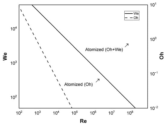
Figure 1.
Atomization transition regions as a function of , and , combined from Refs. [35,36].
Another important phenomenon to consider is droplet collision, which may result in smaller or larger droplets, mainly depending on their relative Weber numbers. However, there are not enough theories available for oxidizer droplets [37,38], and this will not be considered in this work.
2.2. Aspects of Two-Phase Oxidizer Injection
In case of cavitation conditions, is defined as
where the subscripts 1 and 2 refer to upstream and downstream properties, respectively; is the vapor pressure; and is the radius of the orifice inlet fillet. In addition, is a cavitation weighting parameter (square root part of the equation), and is a contraction coefficient [39]. The equation for applies to sharp-edge and rounded injector orifice inlets. In addition, it is only valid for , since higher values of will not form a vena contracta.
Although many of the equations presented in this section focus on showerhead atomizers, similar relations exist for other injectors, and the following sections also apply to them.
Another disclaimer is that since N2O is a two-phase oxidizer under saturation conditions (at ambient temperature), a model is needed to accurately predict the propellant mass flow rate. One of the most widely used tank emptying models is the one proposed by ref. [40], which is based on the two-phase model proposed by ref. [41]. Some years later, a correction was made to Whitmore and Chandler’s model by ref. [42]. This model is known as the Nonhomogeneous Nonequilibrium (NHNE) model, which is a weighting between the Homogeneous Equilibrium Model (HEM) and the Single Phase Incompressible (SPI) model based on the ratio of the characteristic bubble growth time () and the residence time of the liquid in the injector element (). The following relations briefly describe this model:
where , , and are the NHNE, SPI, and HEM mass flow rates, respectively; is the weighting factor; and is the enthalpy change across the injector orifice. All properties are evaluated under saturation conditions as a function of temperature for upstream properties and as a function of pressure for downstream properties, and can be obtained at [43].
It is worth noting that alternative tank emptying models are available, and all of them are described in [44], along with their advantages and disadvantages, such as those proposed by [45]. In addition, ref. [34] provided relevant discussions about the physics of nitrous oxide, and recent research has improved two-phase models for hybrid propulsion, accounting for chocked mass flow conditions [46].
3. Impact on Combustion Stability
3.1. Feed-System Coupled Instability
The dependence of the pre-chamber on the feed-system coupled instability was analyzed by [4,5]. The theory was developed as an adaptation of the Summerfield theory, also known as the theory, for LPREs [47]. It is based on the mass conservation equation, but with a hybrid philosophy. In addition, this model was experimentally validated using two motors from the University of Brasilia (SARA [32]: UnB; Brazil) and the Université Libre de Bruxelles (ULBHRE [48]: ULB; Belgium), with various injector types. Both motors were designed to produce 1 kN of thrust. The critical case for no chamber pressure oscillation for HPRMs is
where , , and are the residence time for the pre-chamber, fuel grain, and combustion chamber, respectively, and defined in Equation (9), is defined as
where is the average chamber pressure; is the average temperature in the port; is the velocity in the port; (for N2O, ) and are the oxidizer and fuel mass flow rates, respectively; and are the chamber volume and temperature; is the pre-chamber length; R is the gas constant; is the port volume (); n is the number of moles in the gas; and is a boundary-layer delay time coefficient, which is also a correction factor obtained experimentally. In general, is approximately 0.55 [49], but it may vary (e.g., 2.05 was used in [4]). Physically, is the time for the oxidizer injection, atomization, and vaporization process to occur; is the time for the boundary-layer properties to adjust to any changes in the oxidizer flux, similar to the boundary-layer lag; and is the time for the gases to flow through the entire combustion chamber.
The velocity at the combustion port inlet can be calculated as shown below:
The growth in oscillation amplitude is defined by (better described at [4,5]) and schematically shown below in Figure 2:

Figure 2.
Scheme of chamber pressure oscillations as a function of : (a) stable, (b) unstable, and (c) marginally stable.
As shown above, the stability limit is achieved when , but any perturbation may induce an increase in the chamber pressure that persists indefinitely. In addition, it is commonly assumed that a maximum of 5% oscillations sets the stability margin [2]. Equation (7) is derived from the following relation [5], in which it is also possible to analyze the role of :
3.2. Pre-Chamber Impact
The following graph, in Figure 3, can be obtained to better understand the stability regions for the stability criterion for HPRMs:
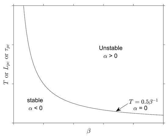
Figure 3.
Effect of T, and on feed-system-coupled instability.
The image above shows the correlation between T and . In addition, the previous statement that defines the stability limit is corroborated. Since T is directly proportional to , as shown in Equation (7), a direct relation is also obtained between the stability criterion and the pre-chamber length, as evidenced by Equation (9). Therefore, .
A standard solution to avoid feed-system coupled instabilities, besides increasing the pre-chamber length, is to use a cavitating venturi in the feed line, since this isolates the combustion chamber from the feed system. However, it is not recommended to implement a cavitation venturi when using N2O, as it may undergo an explosive thermal decomposition reaction. To overcome this issue, choked injectors can also perform this task [34].
4. Design Methodology
The vaporization model is governed by mass and energy conservation laws, which describe (i) droplet–film and (ii) film–gas interactions. These interactions depend on thermophysical parameters and are ruled by the mass transfer, heat transfer, droplet heating rate, droplet acceleration, and gas velocity equations [17,18,19,20,21,26,27,28,50]. This system of equations, along with the effect of each equation on the droplet inside the pre-chamber, is illustrated in Figure 4 and Equation (12). In addition, the assumptions made for the mathematical model are listed below:
- No combustion and chemical reactions, since there is no fuel in the pre-chamber;
- No breakup processes (atomized section of Figure 1) and no thermal decomposition;
- Droplets remain spherical;
- Constant thermophysical properties of the gas inside the pre-chamber;
- One-dimensional model;
- Turbulence effects are neglected;
- No droplet interactions;
- Only convective heat transfer is considered;
- Transient model in a steady-state motor operation;
- Use of liquid oxidizers; and
- Cavitating/choked flow injectors are not considered.
This work considers showerhead injectors in addition to the assumptions above. However, this theory applies to other types of injectors.
where m is the droplet mass; , , , and are the droplet surface area, partial pressure, temperature, and radius, respectively; K is the mass transfer coefficient; is the heat transfer coefficient; is the temperature inside the pre-chamber; is a correction factor for uni-directional mass transfer; Z is a term to take account of the sensible heat taken up by the diffusing vapor; is the latent heat of vaporization of the droplet at temperature ; is the specific heat at a constant pressure of the droplet in the liquid phase; is the droplet velocity; is the relative velocity between the gas and droplet; is the vapor–gas mixture density; and are the gas velocity and density, respectively; is the grain port area; and is the mass flow rate of the vaporization of the oxidizer.

Figure 4.
Scheme of each of the balance equations acting on the vaporizing droplet inside an oxidizer-rich gaseous atmosphere, Control Volume (CV).
The mass transfer coefficient, K, is obtained below:
where is the molecular weight of the evaporating species, D is the coefficient of mass diffusivity, is the universal gas constant (8.31446 J/(molK)), is the mean temperature (), and the Shearwood number, calculated through Ranz Marshall relation [51] is
where Sc is the Schmidt number, which is defined by
where is the mean , which is calculated as shown in Equation (19) (but for ). The correction factor for unidirectional mass transfer is defined as
For the case of HPRM, the coefficient of mass diffusivity is, in reality, the self-diffusion coefficient, since oxidizer droplets are injected in an atmosphere composed of the same fluid. Ref. [52] showed that , when using in cm2/s. In this work, a constant value of 2.6 m2/s is used.
The parameter Z is calculated through
where z is calculated by
where is the gas film thickness and is the mean value of thermal conductivity, calculated below:
where and are the thermal conductivities of the droplet and gas, respectively. The heat transfer coefficient, , is calculated through the Ranz Marshall relation [51], but for the Nusselt number, Equation (21):
where Pr is the Prandtl number, which is calculated below:
where is the mean , which is calculated as shown in Equation (19) (but for ).
The droplet acceleration is derived from the Stokes drag law for a spherical object, and the drag coefficient S is calculated through [53]:
The above equation was derived for Re from 6 to 400; however, ref. [17] successfully tested it with propellant droplets for Reynolds numbers up to 2000. In addition, there are other relations for S [54]. Here, the Reynolds number must be calculated using (Equation (19), but for ), the relative velocity between the gas and droplet, and the vapor–gas mixture density below:
where and are the average molecular weights between the vaporizing droplet and the gas, and this is calculated through
where and are the droplet and gas molecular weights, respectively.
A fourth-order Runge–Kutta numerical method is used to solve the balance equations. The liquid and gaseous oxidizer properties are also obtained by fitting and interpolating data from the National Institute of Standards and Technology (NIST) [43]. The temperature inside the pre-combustion chamber was obtained through experimental testing; however, it can also be calculated using CFD.
It is worth noting that the vaporization model is a properly adapted formulation from Priem’s theory for HPRMs, as it was initially developed for LPREs. Additionally, as a one-dimensional model, it is limited to analyzing a single droplet, with no collisions, turbulence, or recirculation effects, which can significantly impact the results.
A computational algorithm was constructed to calculate the process described in the previous section. The Figure 5 below represents the algorithm workflow:
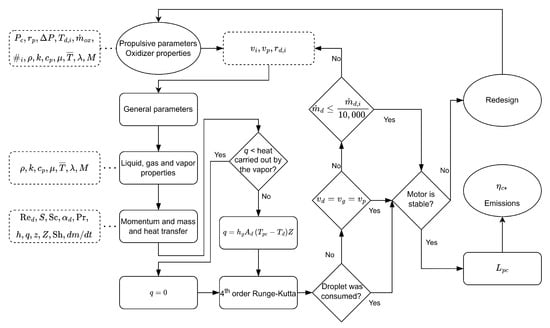
Figure 5.
Algorithm flowchart.
As seen above, there are three convergence criteria (a 0.1% tolerance was used):
- Droplet consumption;
- Mass transfer; and
- Gas and droplet velocities.
The algorithm was implemented in MATLAB R2023b code, which took a few seconds to minutes to simulate each motor fully. Therefore, it is considered a cheap software, computationally and energetically speaking. Observation: It is worth noting that SMD/2.
5. Results, Validation, and Discussions
To validate the proposed algorithm, predictions were benchmarked against two key references: (i) experimental data from eight static-fire tests of SARA and ULBHRE HPRMs (Table 1), and (ii) established empirical design guidelines, notably the ratio from ref. [1]. Figure 6 compares the measured and predicted pre-chamber lengths from these tests, yielding a mean absolute percentage error (MAPE) of 18% and a root-mean-square error of 12%.

Table 1.
Parameters of the tested conditions.
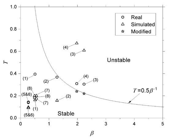
Figure 6.
Stability chart: –T map with experimental and simulated points.
Even the most significant deviation (31% for firing SARA–F5, which experienced an uncommanded oxidizer-temperature rise) induced only a spread in the projected 8% efficiency gain, keeping the energy-saving conclusion robust. A cross-check using the LOX/paraffin dataset of ref. [11] (see Supplementary Figure S1) yielded a similar MAPE (21%), confirming the algorithm’s transferability across oxidizer classes.
In the table above, tests from 1 to 4 are from the UnB motor (SARA), and 5 to 8 are from ULB (ULBHRE). For SARA, the port diameter was 34 mm and the grain length was 101 mm. For ULBHRE, these were 30 mm and 107.5 mm, respectively. In addition, SARA tests were conducted with 16 injectors (6 of them with 1 mm in diameter and 10 of them with 2 mm) and ULBHRE tests, 5 and 6 with 11 injectors (with 1.4 mm), and 7 and 8 with 21 injectors (with 1.4 mm), all of them showerhead. Other injector types were also tested in [4,5]. In the case of the SARA motor, the algorithm was executed with a 2 mm injector orifice, as it produced larger droplets, as estimated by Equation (1), and consequently required a longer pre-chamber.
The obtained results after running the algorithm for the eight motors from Table 1 are presented in Table 2, where the upward red arrow indicates that the simulated value is higher than the real and the downward green arrow indicates the opposite.
Table 2.
Comparison between calculated minimum pre-chamber length and real length.
As seen above, motors 1, 2, 5, and 6 could have their length decreased from the perspective of droplet vaporization. However, motors 3, 4, 7, and 8 need to increase their lengths. With the results presented in Table 1 and Table 2, a stability chart was created to compare how far, or close, the simulated motors were from the real motors from a feed system-coupled instability perspective. This chart is presented in Figure 6.
Analyzing all the presented results, it was determined that the simulated motors with the minimum pre-chamber length required to vaporize an injected droplet corresponded to the real motors regarding combustion stability. Since, from a vaporization perspective, it was possible to decrease in motors 1, 2, 5, and 6. Figure 6 shows that this reduction did not induce instabilities, and this optimization was possible. On the other hand, motors 7 and 8 required a larger to complete droplet vaporization, and this increase was possible since the combustion remained stable. However, motors 3 and 4 would require an increased pre-chamber length to complete vaporization, which would still result in instability.
With these results, an analysis was conducted to achieve a design that would ensure stable combustion for motors 3 and 4. Assuming that all other parameters were constant, this modification was easily achieved by varying the port radius. It is important to mention that to maintain both and constant, the post chamber size would have to be modified, since varies and , where is the residence time related to the post chamber, or mixing chamber. The required and the corresponding decrease as the port radius increases. With the increase in port radius, the motor’s diameter would need to increase to maintain the same burn time, and the grain length would need to be adjusted to preserve the thrust. Figure 7 bellow shows the variation in and as a function of :
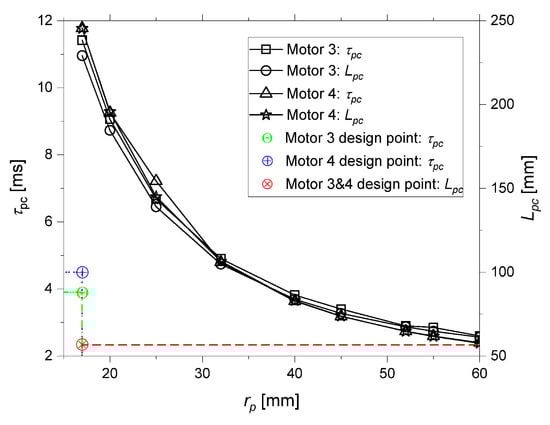
Figure 7.
Variation in and as a function of .
This analysis was extended to the other motors. It was observed that there was a lower impact on combustion stability in the other cases. However, it was also possible to discuss the recommendation of using / = 0.5 [1] from the perspectives of droplet vaporization and feed system-coupled instability. The verifications are shown in Figure 8.
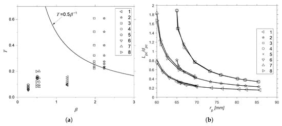
Figure 8.
Impact of on combustion instability (a) and on / (b).
Figure 8a shows the impact of (each point for each motor is a different ) on T and how it was possible to reach stability only by varying the port radius (shown in Figure 6). In Figure 8b, it is possible to observe, through the asymptotic-like behavior, that most of the values of / were concentrated between 0.24 and 0.81. This range was also calculated through the standard deviation of the values. In addition, the mean and median values are presented in Table 3. The values of were calculated to maintain the original burn times of 12 s for SARA and 10 s for ULBHRE. The inputs are shown in Table 1 and were used in [5,32,48] to make the internal ballistic calculations for N2O and paraffin, considering a constant oxidizer mass flow rate.
Table 3.
Values of /.
It is worth noting that these results were presented in [55]. However, in this work, some minor errors in data handling were corrected, and the values were updated accordingly.
The values shown in Table 3 were obtained by excluding values from motors 3 and 4, as they were unstable. However, the modified motors that stabilized them were used. The results presented above are valid for using the value recommended by [1]. Nevertheless, since [1] suggests a range of values for the post-chamber, a better recommendation would be 0.24–0.81. For preliminary sizing, one may assume 0.5 ± 0.25, although caution is advised. However, this range of values should be used cautiously and only in the early design phases. The ideal workflow to obtain an optimized size is, in this order,
- to use the theory presented in this work (vaporization + stability);
- molecular dynamics for droplet scale validation;
- CFD for engine validation; and
- cold and hot experimental testing verification.
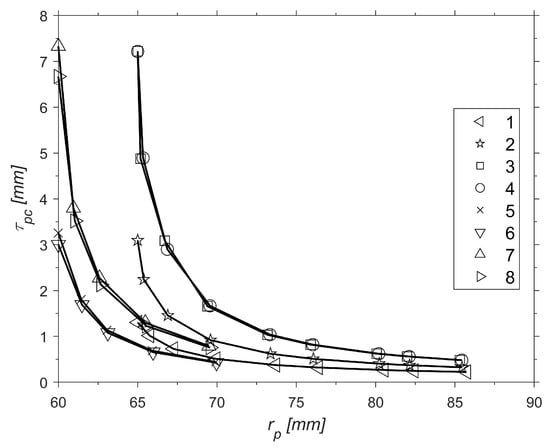
Figure 9.
Impact of on .
The curves above have similar behavior for . This makes sense since is directly proportional to The droplet vaporization results along the axial distance, or pre-chamber length, are shown in Figure 10 for motor 2, as an example.

Figure 10.
Results for motor 2 for droplet vaporization of (a) , and q, and of (b) and .
As observable in Figure 10a, the droplet is heated until it reaches the temperature required to boil the liquid, and then the heat transfer is zeroed. Of course, the sensible heating goes to zero, but latent heat transfer remains, as the phase change is ongoing. Initially, the mass flow rate variation is low because the variation in the terms in Equation (12) is equivalent. The droplet radius and the partial pressure increase with rising temperature, but the mass transfer coefficient and the correction factor for unidirectional mass transfer decrease, as they are inversely proportional to the droplet radius and the partial pressure, respectively. When the vaporization begins, the droplet radius and mass flow rate decrease. Additionally, the droplet velocity decreases significantly with increasing axial distance, as the droplet first expands, thereby increasing its drag. And finally, the gas velocity increases slowly during the droplet expansion phase. However, it increases rapidly in the vaporization phase until it reaches the port velocity .
Figure 11 below shows the droplet radius histories for all motors:

Figure 11.
Results of droplet vaporization of droplet radius with distance.
Although the droplets do not reach a diameter of zero in Figure 11, it is shown in Figure 10a that decreased considerably. The droplet velocity reached the final gas velocity, and both obtained the port velocity (), which are convergence criteria besides the droplet radius zeroing (Figure 5).
An interesting growth in droplet radius was observed at the beginning of the simulation. This is commonly caused by thermal expansion with high-molecular-weight fluids, which expand without losing significant mass through vaporization. In the case of low-molecular-weight fluids, the radius decreases immediately [21].
Ref. [17] also proposed a relation to calculate the characteristic velocity efficiency:
where and are the vaporized fractions of oxidizer and fuel, respectively; is the characteristic velocity calculated for the mixture ratio related to the propellant vaporized fraction (); and is the theoretical characteristic velocity. This work assumed that all fuel was vaporized in all cases (), as it is challenging to predict the correct value. In addition, the calculations were performed assuming the following design point: oxidizer from Table 1, O/F = 8 and bar for SARA [5,32], and O/F = 7.2 and = 24 bar [5,31]. The Figure 12 below shows the results of as a function of the fraction of :

Figure 12.
as a function of the fraction of .
It is perceptible that for low , the did not equal zero, although the cumulative vaporized mass of oxidizer was still near zero. This is explained by the assumption of a constant , which does not represent reality but is a reasonable assumption for higher values of . Moreover, it was assumed that the oxidizer only vaporized in the pre-chamber. However, it can also vaporize inside the combustion port, post-mixing, and in the combustion chamber.
Additionally, as discussed by [17], for LPREs, one may design a pre-combustion chamber with a length shorter than the one required for complete vaporization due to weight, size, or cost restrictions. In addition, an optimization process could be employed to analyze the performance-to-weight ratio. Perhaps an increase in would not be justified due to the low performance gain compared to the weight gain. A range from 90% to 100% seems reasonable. It is pertinent to note the limited availability of comparable, detailed pre-combustion chamber design algorithms in the hybrid rocket literature, which often favors empirical ratios. The present validation against experimental motor data and established heuristics is thus considered a robust assessment for this research area.
Finally, since the impacts the mixture ratio, the reaction products highly depend on the pre-chamber length. The Figure 13 below shows the emissions of CO and CO2 as a function of :
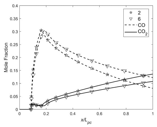
Figure 13.
CO and CO2 mole fraction as a function of the fraction of .
Only motors 2 and 6 are shown, as the variations between them were negligible. As can be observed, the closer to the optimum pre-chamber length in droplet vaporization, the lower the production of CO. However, CO2 increased, but more slowly. Summing both compounds, the graph below, in Figure 14 was obtained:
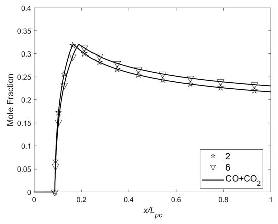
Figure 14.
CO+CO2 mole fraction as a function of the fraction of .
The above graph shows that the lower combined emissions occurred when , resulting in approximately a 31% decrease in the combined emissions. NOx emissions were negligible. The CEA (Chemical Equilibrium with Applications) program [56] was used to calculate the characteristic velocities and combustion products.
6. Conclusions
This work presented an algorithm with a vaporization model capable of optimizing the pre-chambers of hybrid rocket motors by calculating the minimum length required to vaporize an injected droplet. In addition, a verification of feed-system coupled instabilities was performed. The results showed a relation between the port radius, combustion stability, and the pre-chamber length. The range was defined as 0.24 to 0.81. Another characteristic of the vaporization model for HPRMs is that it depends solely on the injector geometry, the oxidizer, and the port diameter, differently from LPREs.
A discussion on the impact of the vaporization fraction and, consequently, the characteristic velocity efficiency as a function of the fraction of pre-combustion chamber length was also presented. As expected, the closer the length was to the calculated required pre-combustion chamber length, the closer the efficiency approached 100%.
The presented study contributes to the design methodology of pre-combustion chambers for hybrid propellant rocket motors, a field of significant interest but with few literature references available. The proposed algorithm can minimize weight, heat transfer losses, nonuniform grain burn, and costs by suppressing feed-system coupled instabilities through tests. Future works will be conducted to study the sensitivity of each design parameter in depth. This will allow us to understand their impact, and better control and optimize the pre-chamber size. In addition, this theory will be extended to the post-combustion chamber for liquefying fuels.
Author Contributions
Conceptualization, M.S.G.; Methodology, M.S.G.; validation, M.S.G., O.S. and A.E.M.B.; writing—original draft preparation, M.S.G.; writing—review and editing, M.S.G., O.S. and A.E.M.B.; supervision, O.S. and A.E.M.B.; funding acquisition, O.S. All authors have read and agreed to the published version of the manuscript.
Funding
This research was funded by Finatec, joint project DELTAV/UnB/FGA, grant 7552, and by CNPq, grant 405499/2022-1.
Data Availability Statement
The data are under embargo while additional experiments are in progress; de-identified data can be provided by the corresponding author upon reasonable request.
Acknowledgments
The authors would like to thank the University of Brasília and that university’s Chemical Propulsion Laboratory (CPL) for their support.
Conflicts of Interest
The authors declare no conflicts of interest.
Abbreviations
| CEA | Chemical Equilibrium with Applications |
| CFD | Computational Fluid Dynamics |
| CV | Control volume |
| HEM | Homogeneous Equilibrium Model |
| HPRM | Hybrid Propellant Rocket Motor |
| LPRE | Liquid Propellant Rocket Engine |
| LOX | Liquid Oxygen |
| MAPE | Mean Absolute Percentage Error |
| MMD | Mass Mean Diameter |
| NHNE | Nonhomogeneous Nonequilibrium |
| NIST | National Institute of Standards and Technology |
| SMD | Sauter Mean Diameter |
| SPI | Single Phase Incompressible |
| ULB | Université Libre de Bruxelles |
| UnB | University of Brasilia |
| HEM | Homogeneous Equilibrium Model |
References
- Humble, R.W.; Henry, C.N.; Larson, W.J. Space Propulsion Analysis and Design; Wiley J: Hoboken, NJ, USA, 1995. [Google Scholar]
- Sutton, G.P.; Biblarz, O. Rocket Propulsion Elements, 9th ed.; Wiley: Hoboken, NJ, USA, 2016. [Google Scholar]
- Chiaverini, M.J.; Kuo, K.K. Fundamentals of Hybrid Rocket Combustion and Propulsion; Progress in Astronautics and Aeronautics; AIAA: Reston, VA, USA, 2007; Volume 218. [Google Scholar]
- Lee, J.; Bertoldi, A.E.M.; Andrianov, A.; Borges, R.A.; Veras, C.A.G. The Role of Pre-Combustion Chamber Design in the Feed-System Coupled Instability of Hybrid Rocket. J. Propuls. Power 2020, 36, 796–805. [Google Scholar] [CrossRef]
- Bertoldi, A.E.M. Study of Combustion Instability in Hybrid Propellant Rocket Motor (in Portuguese). Ph.D. Thesis, University of Brasília, Brasília, Brazil, July 2018. [Google Scholar]
- Sporschill, G. Numerical Approach of a Hybrid Rocket Engine Behaviour—Modelling the Liquid Oxidizer Injection Using a Lagrangian Solver. Master’s Thesis, Polytechnic Institute of Paris, Palaiseau, France, 2017. [Google Scholar]
- Dequick, B.; Lefebvre, M.; Hendrick, P. CFD Simulation of a 1kN Paraffin-Fueled Hybrid Rocket Engine. In Proceedings of the AIAA Propulsion and Energy Forum, Virtual, 24–28 August 2020. [Google Scholar]
- Paccagnella, E.; Gelain, R.; Barato, F.; Pavarin, D.; Berg, P.v.d.; Barreiro, F. CFD Simulations of Self-Pressurized Nitrous Oxide Hybrid Rocket Motors. In Proceedings of the AIAA Propulsion and Energy Forum, Cincinnati, OH, USA, 9–11 July 2018. [Google Scholar]
- Balasubramanian, A.K.; Kumar, V.; Nakod, P.; Schütze, J.; Rajan, A. Multiscale Modelling of a Doublet Injector Using Hybrid VOF-DPM Method. In Proceedings of the AIAA Scitech Forum, Orlando, FL, USA, 6–10 January 2020. [Google Scholar]
- Costa, F.; Vieira, R. Preliminary Analysis of Hybrid Rockets for Launching Nanosats into LEO. J. Braz. Soc. Mech. Sci. Eng. 2010, 32, 502–509. [Google Scholar] [CrossRef]
- Gamper, E.; Hink, R. Design and Test of Nitrous Oxide Injectors for a Hybrid Rocket Engine. In Proceedings of the Deutscher Luft-und Raumfahrtkongress, Stuttgart, Germany, 10–12 September 2013. [Google Scholar]
- Consolini, L.; Aggarwal, S.K.; Sohail, M.T. A Molecular Dynamics Simulation of Droplet Evaporation. Int. J. Heat Mass Transf. 2003, 46, 3179–3188. [Google Scholar] [CrossRef]
- Turns, S.R. An Introduction to Combustion: Concepts and Applications, 3rd ed.; McGraw-Hill: New York, NY, USA, 2011. [Google Scholar]
- Spalding, D.B. Combustion in Liquid-Fuel Rocket Motors. Aeronaut. Q. 1959, 10, 1–27. [Google Scholar] [CrossRef]
- Spalding, D.B. A One-Dimensional Theory of Liquid-Fuel Rocket Combustion; Aeronautical Research Council: London, UK, 1959. [Google Scholar]
- Adler, J. A One-Dimensional Theory of Liquid-Fuel Rocket Combustion. Part II. The Influence of Chemical Reaction; Aeronautical Research Council: London, UK, 1959. [Google Scholar]
- Priem, R.J.; Heidmann, M.F. Vaporization of Propellants in Rocket Engines. ARS J. 1959, 29, 836–842. [Google Scholar] [CrossRef]
- Priem, R.J. Propellant Vaporization as a Criterion for Rocket Engine Design; Calculations of Chamber Length to Vaporize a Single n-Heptane Drop; Technical Note 3985; NACA: Washington, DC, USA, 1957. [Google Scholar]
- Priem, R.J. Propellant Vaporization as a Criterion for Rocket Engine Design; Calculations Using Various Log-Probability Distributions of Heptane Drops; Technical Note 4098; NACA: Washington, DC, USA, 1957. [Google Scholar]
- Priem, R.J. Propellant Vaporization as a Criterion for Rocket Engine Design; Calculations of Chamber Length to Vaporize Various Propellants; Technical Note 3883; NACA: Washington, DC, USA, 1958. [Google Scholar]
- Priem, R.J.; Borman, G.L.; Walkil, M.M.E.; Uyehara, O.A.; Myers, P.S. Experimental and Calculated Histories of Vaporizing Fuel Drops; Technical Note 3988; NACA: Washington, DC, USA, 1957. [Google Scholar]
- Khan, T.; Qamar, I.; Shah, F.; Akhtar, K.; Akhtar, R. Model for Fuel Droplet Evaporation in Combustion Chamber of Liquid Propellant Rocket Engines. J. Eng. Appl. Sci. 2018, 37, 1–10. [Google Scholar]
- Khan, T.; Qamar, I. Factors Affecting Characteristic Length of the Combustion Chamber of Liquid Propellant Rocket Engines. Mehran Univ. Res. J. Eng. Technol. 2019, 38, 729–744. [Google Scholar] [CrossRef]
- Salvador, C.A.V. Mathematical Model of Bipropellant Combustion Chambers (in Portuguese). Master’s Thesis, National Institute for Space Research, São Paulo, Brazil, 2004. [Google Scholar]
- Wang, Z.G. Internal Combustion Process of Liquid Rocket Engines: Modeling and Numerical Simulations; John Wiley & Sons: Singapore, 2016. [Google Scholar]
- Hegazy, M.; Belal, H.M.; Makled, A.; Al-Sanabawy, M.A. Validation of a Simplified Model for Liquid Propellant Rocket Engine Combustion Chamber Design. In Proceedings of the 19th International Conference on Applied Mechanics and Mechanical Engineering (AMME-19), Cairo, Egypt, 7–9 April 2020; Volume 973. [Google Scholar]
- Belal, H.M. Vaporization-Controlled Simplified Model for Liquid Propellant Rocket Engine Combustion Chamber Design. In Proceedings of the 18th International Conference on Aerospace Sciences & Aviation Technology, Cairo, Egypt, 9–11 April 2019; Volume 610. [Google Scholar]
- Belal, H.M. Numerical Simulation of Spray Combustion. Master’s Thesis, Military Technical College, Cairo, Egypt, 2010. [Google Scholar]
- Gontijo, M.S.; Fischer, G.A.A.; Costa, F.S. Evaluation of SMD Effects on Characteristic Lengths of Liquid Rocket Engines Using Ethanol/LOX and RP-1/LOX. In Proceedings of the 18th Brazilian Congress of Thermal Sciences and Engineering, Bento Gonçalves, Brazil, 16–20 November 2020. [Google Scholar]
- Karabeyoglu, A.; Dyer, J.; Stevens, J.; Cantwell, B. Modeling of N2O Decomposition Events. In Proceedings of the 44th AIAA/ASME/SAE/ASEE Joint Propulsion Conference & Exhibit, Hartford, CT, USA, 21–23 July 2008. [Google Scholar]
- Bouziane, M.; Bertoldi, A.E.M.; Hendrick, P.; Lefebvre, M. Experimental Investigation of the Axial Oxidizer Injectors Geometry on A 1-kN Paraffin-Fueled Hybrid Rocket Motor. FirePhysChem 2021, 1, 231–243. [Google Scholar] [CrossRef]
- Andrianov, A.; Shynkarenko, O.; Bertoldi, A.E.M.; Barcelos, M.N.D.J.; Veras, C.A.G. Concept and Design of the Hybrid Test-Motor for Development of a Propulsive Decelerator of SARA Reentry Capsule. In Proceedings of the 51st AIAA/SAE/ASEE Joint Propulsion Conference, Orlando, FL, USA, 27–29 July 2015. [Google Scholar]
- Lefebvre, A.H.; McDonell, V.G. Atomization and Sprays, 2nd, ed.; Taylor & Francis Group: Abingdon, UK, 2007. [Google Scholar]
- Waxman, B.S. Investigation of Injectors for Use with High Vapor Pressure Propellants with Applications to Hybrid Rockets. Ph.D. Thesis, Stanford University, Stanford, CA, USA, 2014. [Google Scholar]
- Saeedipour, M.; Schneiderbauer, S.; Pirker, S.; Bozorgi, S. A Numerical and Experimental Study of Flow Behavior in High Pressure Die Casting. Magnes. Technol. 2014, 2016, 185–190. [Google Scholar]
- Schimdt, P.; Walzel, P. Zerstäuben von Flüssigkeiten. Phys. Unserer Zeit 1984, 15, 113–120. [Google Scholar] [CrossRef]
- Qian, J.; Law, C.K. Regimes of Coalescence and Separation in Droplet Collision. J. Fluid Mech. 1997, 31, 59–80. [Google Scholar] [CrossRef]
- Gontijo, M.S. Investigation of Pressure-Swirl Injectors Sprays Interaction in Liquid Propellant Rocket Engines. Master’s Thesis, Aeronautics Institute of Technology, Sao Jose dos Campos, Brazil, 2024. [Google Scholar]
- Nurick, W.H. Orifice Cavitation and Its Effect on Spray Mixing. J. Fluids Eng. 1976, 98, 681. [Google Scholar] [CrossRef]
- Whitmore, S.A.; Chandler, S.N. Engineering Model for Self-Pressurizing Saturated-N2O-Propellant Feed Systems. J. Propuls. Power 2010, 26, 706–714. [Google Scholar] [CrossRef]
- Dyer, J.; Doran, E.; Dunn, Z.; Lohner, K.; Zilliac, G.; Cantwell, B. Modeling Feed System Flow Physics for Self-Pressurizing Propellants. In Proceedings of the 43rd AIAA/ASME/SAE/ASEE Joint Propulsion Conference & Exhibit, Cincinnati, OH, USA, 8–11 July 2007. [Google Scholar]
- Solomon, B.J. Engineering Model to Calculate Mass Flow Rate of a Two-Phase Saturated Fluid Through an Injector Orifice. Master’s Thesis, Utah State University, Logan, UT, USA, 2011. [Google Scholar]
- Linstrom, P.J. A Guide to the NIST Chemistry WebBook; National Institute of Standards and Technology (NIST): Gaithersburg, MD, USA, 2022. [Google Scholar]
- Zimmerman, J.E.; Waxman, B.S.; Cantwell, B.J.; Zilliac, G.G. Review and Evaluation of Models for Self-Pressurizing Propellant Tank Dynamics. In Proceedings of the 49th AIAA/ASME/SAE/ASEE Joint Propulsion Conference & Exhibit, San Jose, CA, USA, 14–17 July 2013. [Google Scholar]
- Zilliac, G.G.; Karabeyoglu, A. Modeling of Propellant Tank Pressurization. In Proceedings of the 41st AIAA/ASME/SAE/ASEE Joint Propulsion Conference & Exhibit, Tucson, AZ, USA, 11–13 July 2005. [Google Scholar]
- Niño, E.V.; Razavi, M.R. Design of Two-Phase Injectors Using Analytical and Numerical Methods with Application to Hybrid Rockets. In Proceedings of the AIAA Propulsion and Energy Forum, Indianapolis, IN, USA, 19–22 August 2019. [Google Scholar]
- Summerfield, M.A. A Theory of Unstable Combustion in Liquid Propellant Rocket Systems. J. Am. Rocket. Soc. 1951, 21, 108–114. [Google Scholar] [CrossRef]
- Bouziane, M.; Bertoldi, E.A.M.; Lee, D.; Milova, P.; Hendrick, P.; Lefebvre, M. Design and Experimental Evaluation of Liquid Oxidizer Injection System for Hybrid Rocket Motors. In Proceedings of the 7th European Conference for Aeronautics and Space Sciences, Milan, Spain, 3–6 July 2017. [Google Scholar]
- Karabeyoglu, A.M.; Zilwa, S.; Cantwell, B.; Zilliac, G. Modeling of Hybrid Rocket Low Frequency Instabilities. J. Propuls. Power 2005, 21, 1107–1116. [Google Scholar] [CrossRef]
- Sirignano, W.A. Fluid Dynamics and Transport of Droplets and Sprays, 2nd ed.; Cambridge University Press: New York, NY, USA, 2012. [Google Scholar]
- Ranz, W.E.; Marshall, W.R. Evaporation from Drops. Chem. Eng. Prog. 1952, 48, 141–146. [Google Scholar]
- Chapman, S.; Cowling, T.G. Mathematical Theory of Non-Uniform Gases, 3rd ed.; Cambridge University Press: New York, NY, USA, 1991. [Google Scholar]
- Ingebo, R.D. Vaporization Rates and Drag Coefficients for Isooctane Sprays in Turbulent Air Streams; Technical Note 3265; NACA: Washington, DC, USA, 1954. [Google Scholar]
- Abramzon, B.; Sirignano, W.A. Droplet Vaporization Model for Spray Combustion Calculations. Int. J. Heat Mass Transf. 1989, 32, 1605–1618. [Google Scholar] [CrossRef]
- Gontijo, M.S.; Filho, R.B.N.; Domingos, C.H.F.L. Design of Pre-Combustion Chambers for Hybrid Propellant Rocket Motors and Related Aspects. In Proceedings of the AIAA Scitech Forum, National Harbor, MD, USA & Online, 23–27 January 2023. [Google Scholar]
- Gordon, S.; McBride, B.J. Computer Program for Calculation of Complex Chemical Equilibrium Compositions and Applications—I. Analysis; NASA-RP-1311; NASA: Washington, DC, USA, 1994. [Google Scholar]
Disclaimer/Publisher’s Note: The statements, opinions and data contained in all publications are solely those of the individual author(s) and contributor(s) and not of MDPI and/or the editor(s). MDPI and/or the editor(s) disclaim responsibility for any injury to people or property resulting from any ideas, methods, instructions or products referred to in the content. |
© 2025 by the authors. Licensee MDPI, Basel, Switzerland. This article is an open access article distributed under the terms and conditions of the Creative Commons Attribution (CC BY) license (https://creativecommons.org/licenses/by/4.0/).