


A Review of CO2 Clathrate Hydrate Technology: From Lab-Scale Preparation to Cold Thermal Energy Storage Solutions


Abstract
1. Introduction
2. CO2 Hydrate Formation
2.1. When and Where Does Gas Hydrate Formation Occur?
2.2. Memory Effect in Gas Hydrate Formation
- -
- The residual structure mechanism;
- -
- The gas supersaturation mechanism;
- -
- The impurity imprinting theorem (for situations when hydrate formation takes place in porous media, i.e., fixed-bed continuous-flow reactors).
2.3. Conditions Needed for CO2 Hydrate Formation
2.4. Hydrate Induction Time
3. Hydrate Formation Promoters
3.1. Thermodynamic Promoters
3.2. Kinetic Hydrate Promoters
3.2.1. Surfactants
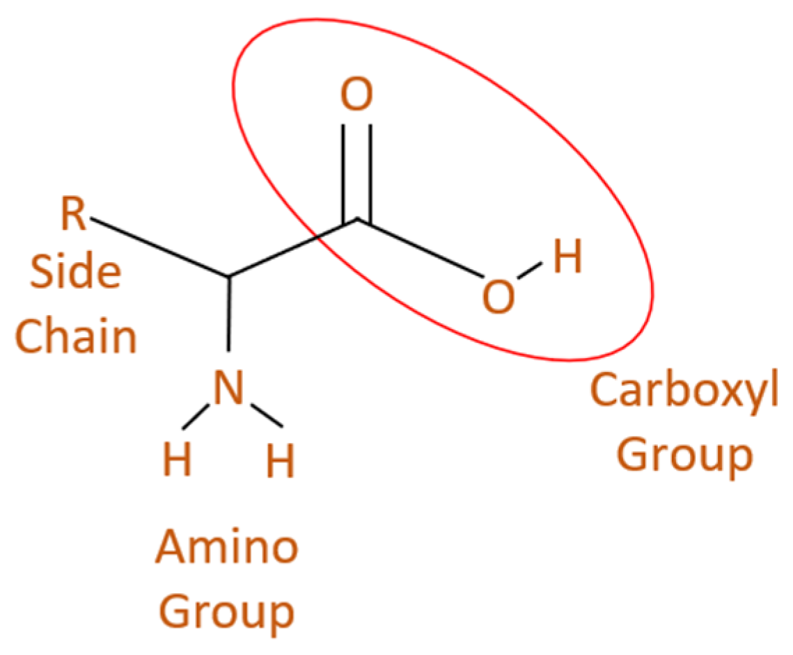
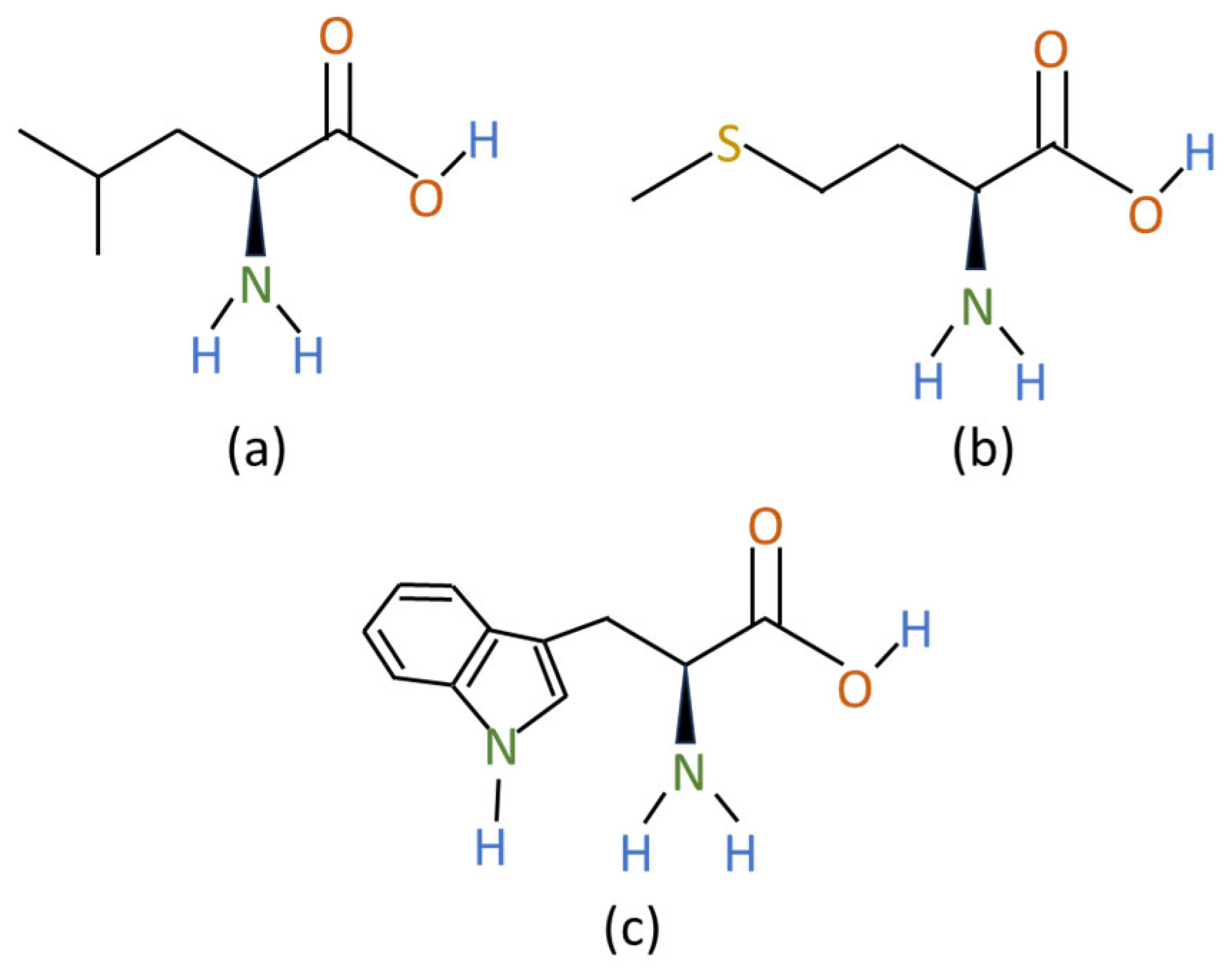
3.2.2. Amino Acids
3.2.3. Nanoparticles/Solid Particles
3.3. Promoters Efficiency and Process Scalability Challenges
3.4. Regulatory Standards Related to CO2 Hydrate Promoters and Surfactants
4. Experimental Setups Used in CO2 Hydrate Formation Experiments
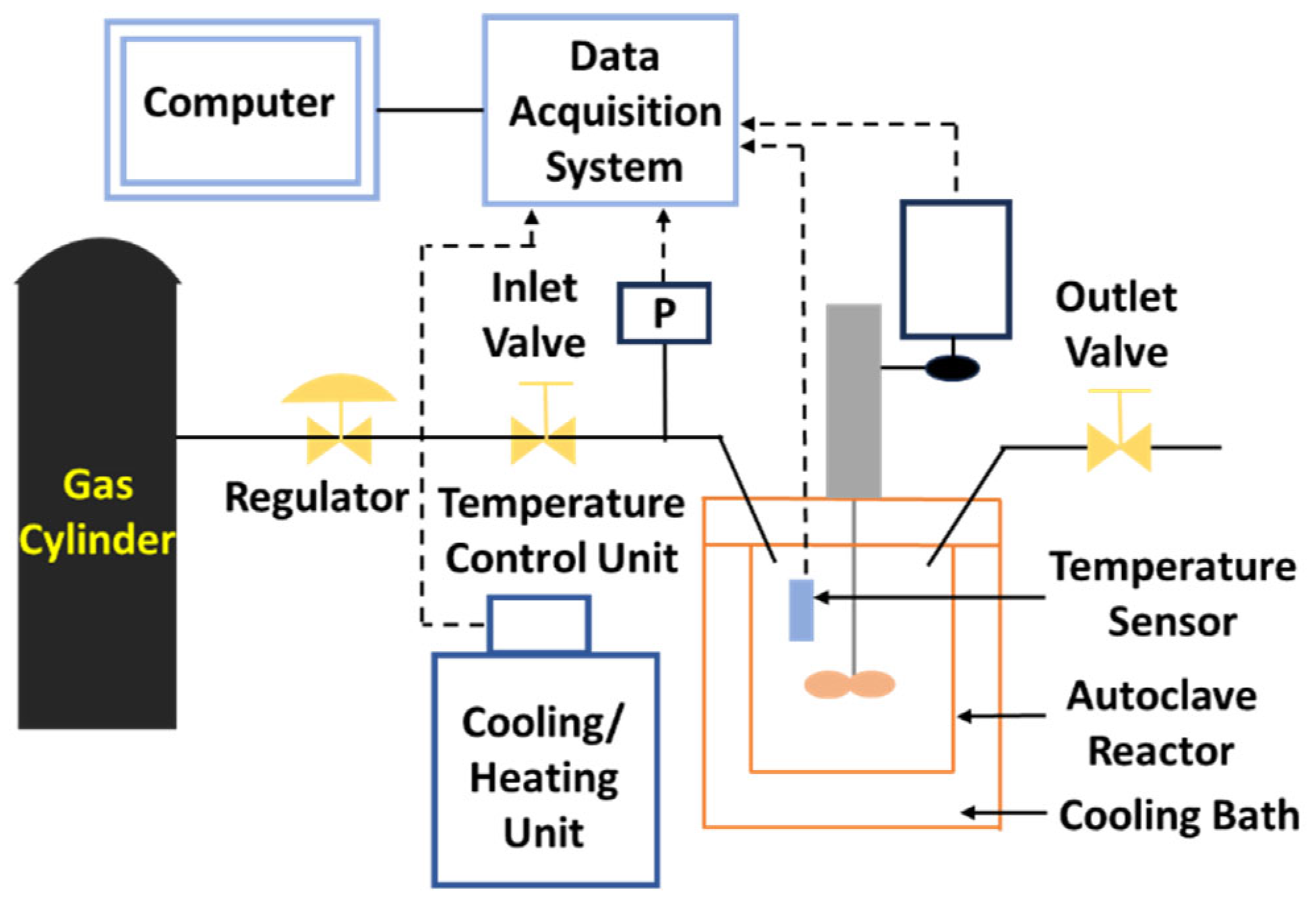
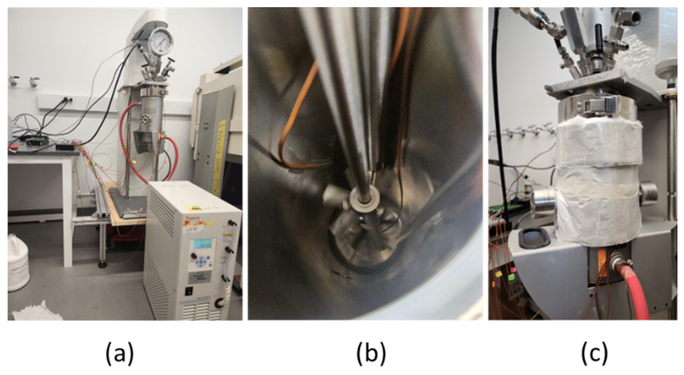
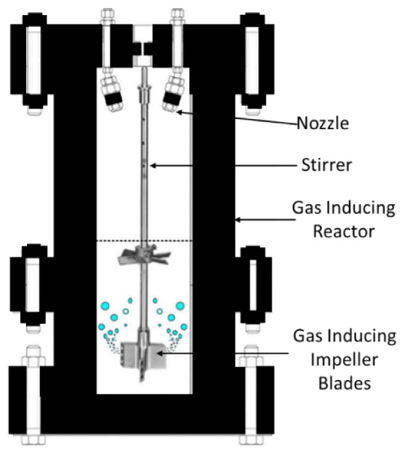
4.1. Stirred Reactors
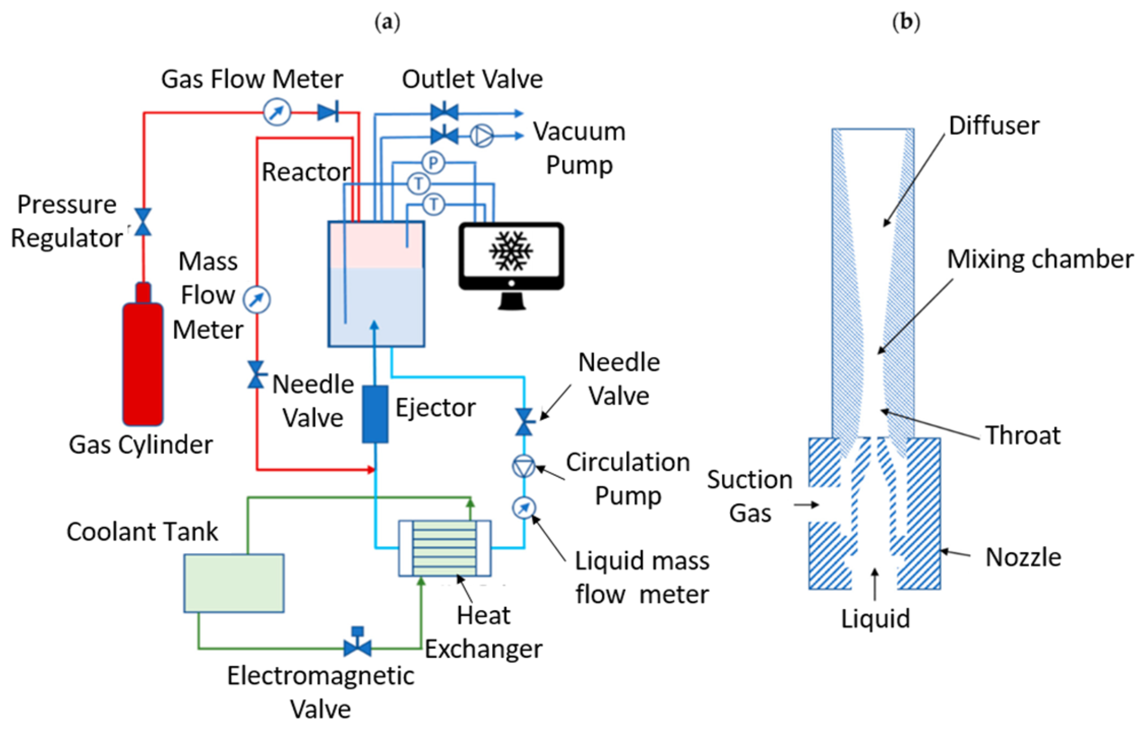
4.2. Bubble-Forming, Ejector, and Continuous-Flow Reactors
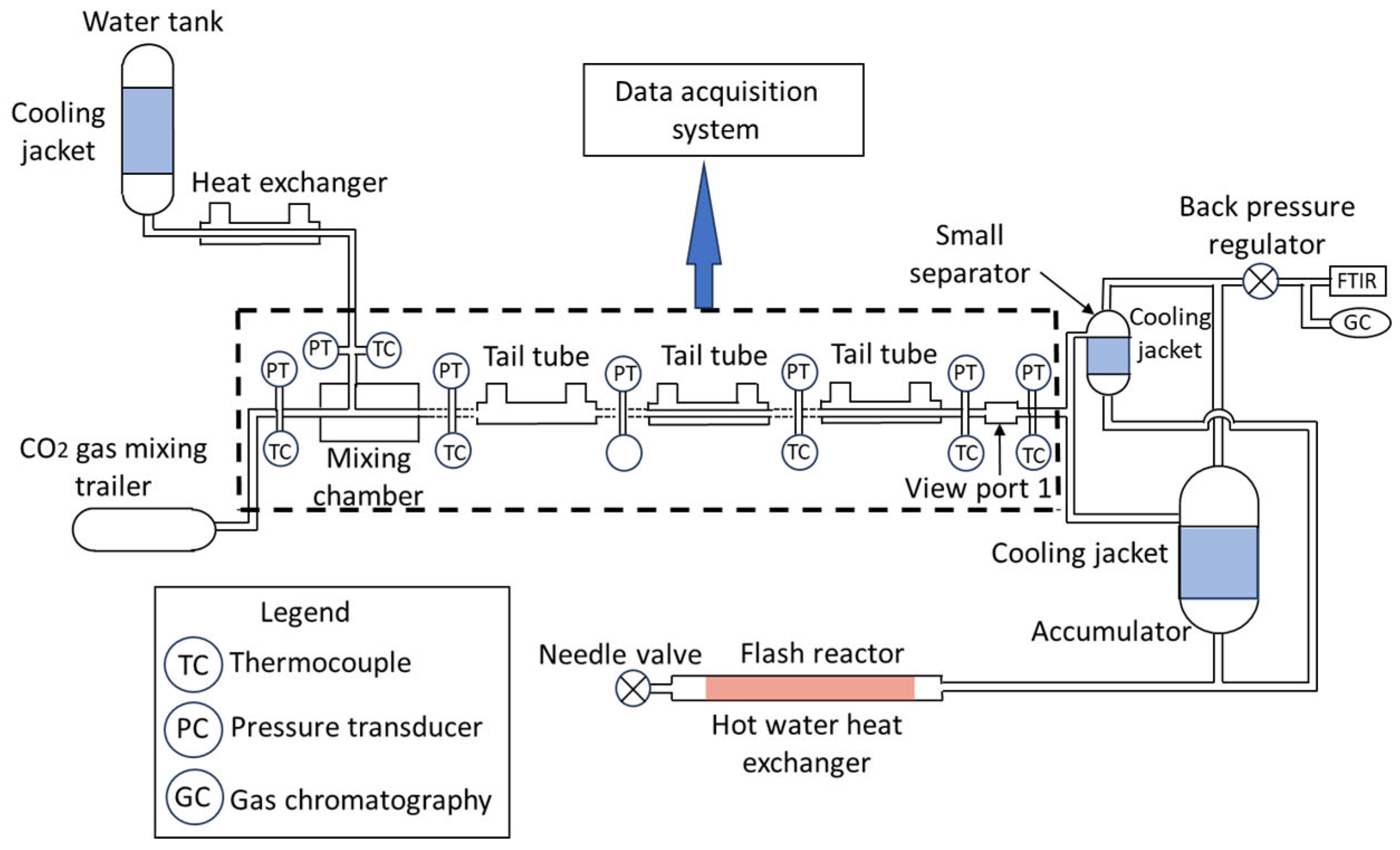
4.3. Continuous Process Reactor
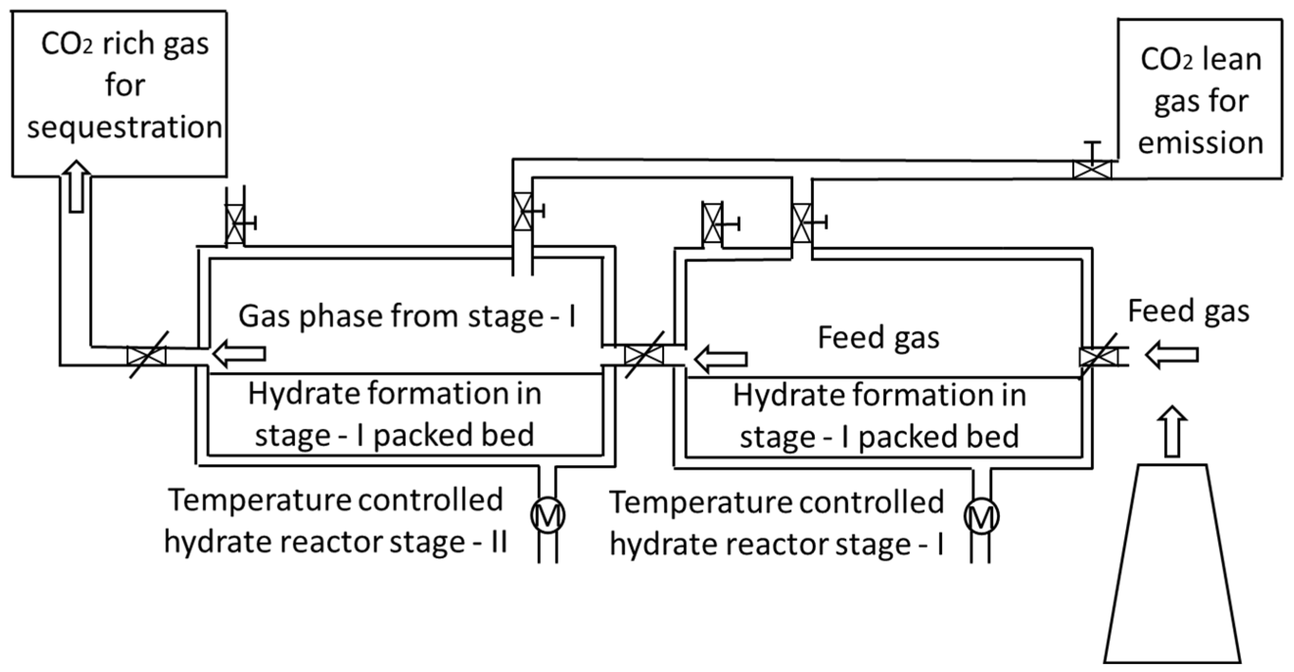
4.4. Fixed-Bed Reactors
4.5. Comparisons of Different Types of CO2 Hydrate Reactors
4.6. Challenges in Scaling CO2 Hydrate Systems
5. Typical Characterization Techniques Used in CO2 Hydrates Analysis
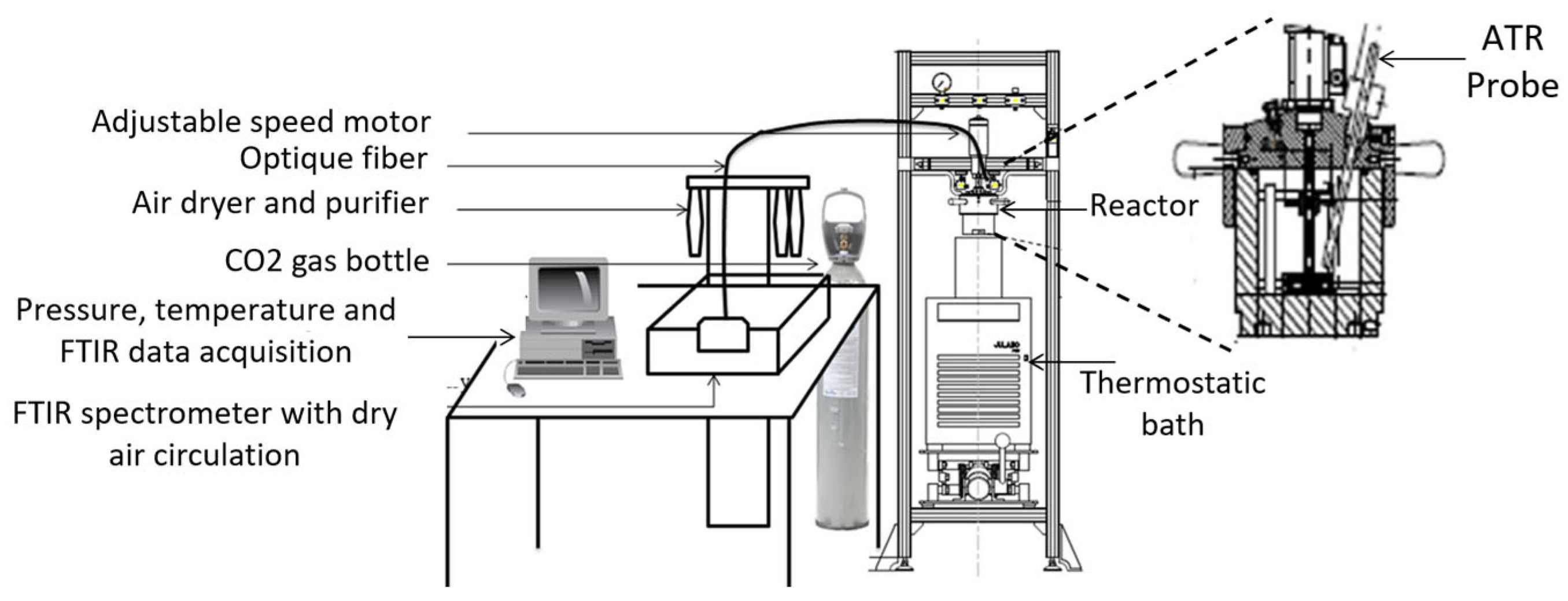
5.1. Fourier-Transform Infrared (FTIR) Spectroscopy
5.2. X-Ray Diffraction (XRD)
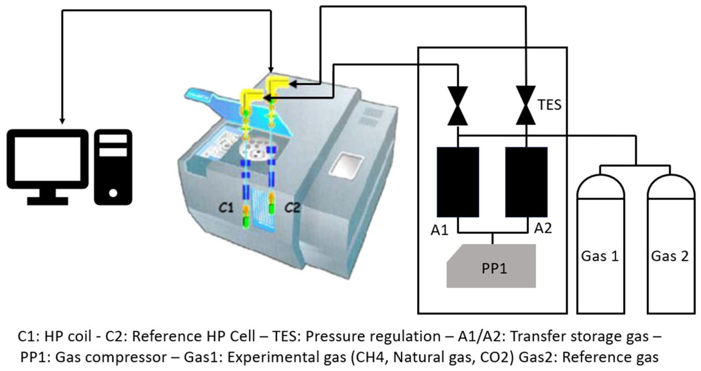
5.3. High Pressure Differential Scanning Calorimetry (HP-DSC)
5.4. T-History Method
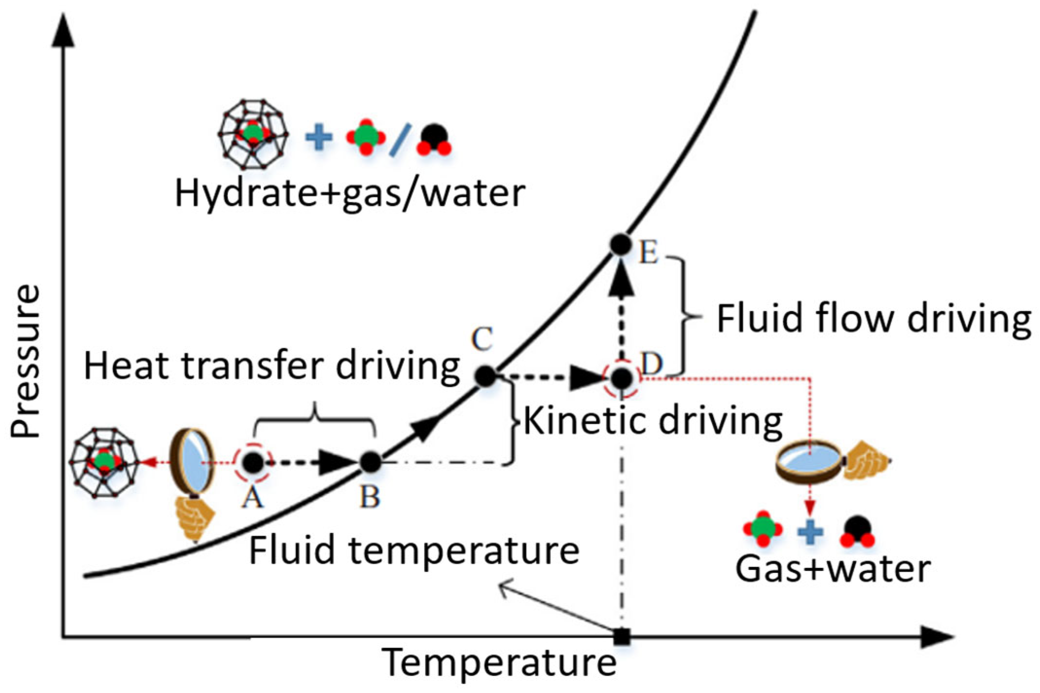
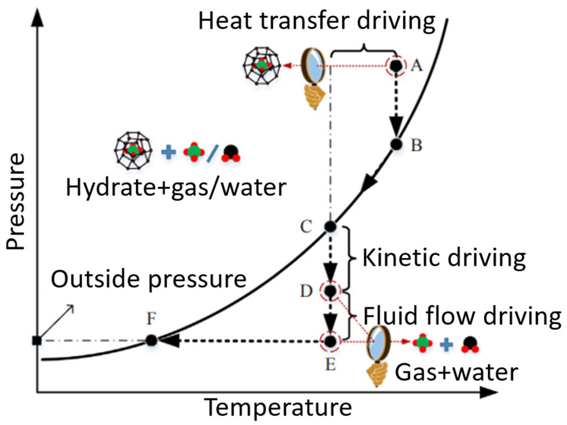
6. Dissociation of CO2 Clathrate Hydrates and Advancements in Analysis of Phase-Change Enthalpy
7. Future Heat Storage, Refrigeration, and Space Conditioning Applications
7.1. CO2 Hydrate Used in Air-Conditioning (AC) System
7.2. CO2 Hydrate Slurry as a Secondary Refrigerant System
7.3. Cold Thermal Energy Storage (CTES)
8. Potential Consequences of Using CO2 Hydrates
9. Research Gaps and Future Research Directions
Author Contributions
Funding
Conflicts of Interest
References
- Lachheb, M.; Younsi, Z.; Youssef, N.; Bouadila, S. Enhancing Building Energy Efficiency and Thermal Performance with PCM-Integrated Brick Walls: A Comprehensive Review. Build. Environ. 2024, 256, 111476. [Google Scholar] [CrossRef]
- Dincer, I. On Thermal Energy Storage Systems and Applications in Buildings. Energy Build. 2002, 34, 377–388. [Google Scholar] [CrossRef]
- TCBU Editorial Thermal Control Magazine. 16 June 2023. Available online: https://www.thermalcontrolmagazine.com/ (accessed on 15 May 2025).
- Franco, A.; Cillari, G. Energy Sustainability of Food Stores and Supermarkets through the Installation of PV Integrated Plants. Energies 2021, 14, 5678. [Google Scholar] [CrossRef]
- Sharma, A.; Tyagi, V.V.; Chen, C.R.; Buddhi, D. Review on Thermal Energy Storage with Phase Change Materials and Applications. Renew. Sustain. Energy Rev. 2009, 13, 318–345. [Google Scholar] [CrossRef]
- Jouhara, H.; Żabnieńska-Góra, A.; Khordehgah, N.; Ahmad, D.; Lipinski, T. Latent Thermal Energy Storage Technologies and Applications: A Review. Int. J. Thermofluids 2020, 5–6, 100039. [Google Scholar] [CrossRef]
- Awan, H.T.A.; Kumar, L.; Wong, W.P.; Walvekar, R.; Khalid, M. Recent Progress and Challenges in MXene-Based Phase Change Material for Solar and Thermal Energy Applications. Energies 2023, 16, 1977. [Google Scholar] [CrossRef]
- Lamrani, B.; Johannes, K.; Kuznik, F. Phase Change Materials Integrated into Building Walls: An Updated Review. Renew. Sustain. Energy Rev. 2021, 140, 110751. [Google Scholar] [CrossRef]
- Nishad, S.; Krupa, I. Phase Change Materials for Thermal Energy Storage Applications in Greenhouses: A Review. Sustain. Energy Technol. Assess. 2022, 52, 102241. [Google Scholar] [CrossRef]
- Bodner, J.; Koksharov, J.; Dammel, F.; Stephan, P. Analysis of Low-temperature Pumped Thermal Energy Storage Systems Based on a Transcritical CO2 Charging Process. Energy Sci. Eng. 2023, 11, 3289–3306. [Google Scholar] [CrossRef]
- Fournaison, L.; Delahaye, A.; Chatti, I.; Petitet, J.-P. CO2 Hydrates in Refrigeration Processes. Ind. Eng. Chem. Res. 2004, 43, 6521–6526. [Google Scholar] [CrossRef]
- Chen, H.; Han, B.; Lang, C.; Wen, M.; Fan, B.; Liu, Z. Hydrates for Cold Storage: Formation Characteristics, Stability, and Promoters. Appl. Sci. 2021, 11, 10470. [Google Scholar] [CrossRef]
- Jäger, A.; Vinš, V.; Gernert, J.; Span, R.; Hrubý, J. Phase Equilibria with Hydrate Formation in H2O+CO2 Mixtures Modeled with Reference Equations of State. Fluid Phase Equilib. 2013, 338, 100–113. [Google Scholar] [CrossRef]
- Liu, X.; Cao, Q.; Xu, D.; Luo, S.; Guo, R. Improved Methane Storage Capacity of Methane Hydrate Promoted by Vesicles from Carboxylate Surfactants and Quaternary Ammonium. J. Nat. Gas. Sci. Eng. 2021, 93, 103990. [Google Scholar] [CrossRef]
- Izquierdo-Ruiz, F.; Otero-de-la-Roza, A.; Contreras-García, J.; Prieto-Ballesteros, O.; Recio, J. Effects of the CO2 Guest Molecule on the SI Clathrate Hydrate Structure. Materials 2016, 9, 777. [Google Scholar] [CrossRef]
- Sloan, E.D., Jr.; Koh, C.A. Clathrate Hydrates of Natural Gases; CRC Press: Boca Raton, FL, USA, 2007; ISBN 9780429129148. [Google Scholar]
- Sun, Q.; Kang, Y.T. Review on CO2 Hydrate Formation/Dissociation and Its Cold Energy Application. Renew. Sustain. Energy Rev. 2016, 62, 478–494. [Google Scholar] [CrossRef]
- Sinehbaghizadeh, S.; Saptoro, A.; Mohammadi, A.H. CO2 Hydrate Properties and Applications: A State of the Art. Prog. Energy Combust. Sci. 2022, 93, 101026. [Google Scholar] [CrossRef]
- Ma, Z.W.; Zhang, P.; Bao, H.S.; Deng, S. Review of Fundamental Properties of CO2 Hydrates and CO2 Capture and Separation Using Hydration Method. Renew. Sustain. Energy Rev. 2016, 53, 1273–1302. [Google Scholar] [CrossRef]
- Wroblewsk, S. On the Composition of the Hydrate of Carbonic Acid. Acad. Sci. 1882, 94, 954–958. Available online: https://www.chemeurope.com/en/encyclopedia/Zygmunt_Florenty_Wr%C3%B3blewski.html (accessed on 15 May 2025). (In French).
- Ke, W.; Svartaas, T.M.; Chen, D. A Review of Gas Hydrate Nucleation Theories and Growth Models. J. Nat. Gas. Sci. Eng. 2019, 61, 169–196. [Google Scholar] [CrossRef]
- Nguyen, N.N.; Galib, M.; Nguyen, A.V. Critical Review on Gas Hydrate Formation at Solid Surfaces and in Confined Spaces—Why and How Does Interfacial Regime Matter? Energy Fuels 2020, 34, 6751–6760. [Google Scholar] [CrossRef]
- Farhang, F.; Nguyen, A.V.; Sewell, K.B. Fundamental Investigation of the Effects of Hydrophobic Fumed Silica on the Formation of Carbon Dioxide Gas Hydrates. Energy Fuels 2014, 28, 7025–7037. [Google Scholar] [CrossRef]
- Sowa, B.; Maeda, N. Statistical Study of the Memory Effect in Model Natural Gas Hydrate Systems. J. Phys. Chem. A 2015, 119, 10784–10790. [Google Scholar] [CrossRef] [PubMed]
- Uchida, T.; Yamazaki, K.; Gohara, K. Gas Nanobubbles as Nucleation Acceleration in the Gas-Hydrate Memory Effect. J. Phys. Chem. C 2016, 120, 26620–26629. [Google Scholar] [CrossRef]
- Kou, X.; Feng, J.-C.; Li, X.-S.; Wang, Y.; Chen, Z.-Y. Memory Effect of Gas Hydrate: Influencing Factors of Hydrate Reformation and Dissociation Behaviors. Appl. Energy 2022, 306, 118015. [Google Scholar] [CrossRef]
- Bollengier, O.; Choukroun, M.; Grasset, O.; Le Menn, E.; Bellino, G.; Morizet, Y.; Bezacier, L.; Oancea, A.; Taffin, C.; Tobie, G. Phase Equilibria in the H2O–CO2 System between 250–330K and 0–1.7GPa: Stability of the CO2 Hydrates and H2O-Ice VI at CO2 Saturation. Geochim. Cosmochim. Acta 2013, 119, 322–339. [Google Scholar] [CrossRef]
- Zhang, Z.; Guo, G.-J.; Wu, N.; Kusalik, P.G. Molecular Insights into Guest and Composition Dependence of Mixed Hydrate Nucleation. J. Phys. Chem. C 2020, 124, 25078–25086. [Google Scholar] [CrossRef]
- Veluswamy, H.P.; Kumar, R.; Linga, P. Hydrogen Storage in Clathrate Hydrates: Current State of the Art and Future Directions. Appl. Energy 2014, 122, 112–132. [Google Scholar] [CrossRef]
- Zhou, X.; Zhou, J.; Chen, P.; Wen, H.; Zang, X.; Fan, S.; Liang, D. Spectral Analysis on the Raman Peaks of CH4, CO2, and N2 in the Hydrate Phase. Energy Fuels 2025, 39, 1579–1587. [Google Scholar] [CrossRef]
- Dholabhai, P.D.; Kalogerakis, N.; Bishnoi, P.R. Equilibrium Conditions for Carbon Dioxide Hydrate Formation In Aqueous Electrolyte Solutions. J. Chem. Eng. Data 1993, 38, 650–654. [Google Scholar] [CrossRef]
- Hammerschmidt, E.G. Formation of Gas Hydrates in Natural Gas Transmission Lines. Ind. Eng. Chem. 1934, 26, 851–855. [Google Scholar] [CrossRef]
- Ng, H.-J.; Robinson, D.B. Hydrate Formation in Systems Containing Methane, Ethane, Propane, Carbon Dioxide or Hydrogen Sulfide in the Presence of Methanol. Fluid Phase Equilib. 1985, 21, 145–155. [Google Scholar] [CrossRef]
- Miller, S.L.; Smythe, W.D. Carbon Dioxide Clathrate in the Martian Ice Cap. Science 1970, 170, 531–533. [Google Scholar] [CrossRef]
- Adamson, A.W.; Jones, B.R. Physical Adsorption of Vapors on Ice. IV. Carbon Dioxide. J. Colloid. Interface Sci. 1971, 37, 831–835. [Google Scholar] [CrossRef]
- Wendland, M.; Hasse, H.; Maurer, G. Experimental Pressure–Temperature Data on Three- and Four-Phase Equilibria of Fluid, Hydrate, and Ice Phases in the System Carbon Dioxide–Water. J. Chem. Eng. Data 1999, 44, 901–906. [Google Scholar] [CrossRef]
- Yasuda, K.; Ohmura, R. Phase Equilibrium for Clathrate Hydrates Formed with Methane, Ethane, Propane, or Carbon Dioxide at Temperatures below the Freezing Point of Water. J. Chem. Eng. Data 2008, 53, 2182–2188. [Google Scholar] [CrossRef]
- Kimura, H.; Fuseya, G.; Takeya, S.; Hachikubo, A. Carbon Isotope Fractionation during the Formation of CO2 Hydrate and Equilibrium Pressures of 12CO2 and 13CO2 Hydrates. Molecules 2021, 26, 4215. [Google Scholar] [CrossRef]
- Ohno, H.; Oyabu, I.; Iizuka, Y.; Hondoh, T.; Narita, H.; Nagao, J. Dissociation Behavior of C2H6 Hydrate at Temperatures below the Ice Point: Melting to Liquid Water Followed by Ice Nucleation. J. Phys. Chem. A 2011, 115, 8889–8894. [Google Scholar] [CrossRef]
- Melnikov, V.P.; Nesterov, A.N.; Podenko, L.S.; Reshetnikov, A.M.; Shalamov, V.V. NMR Evidence of Supercooled Water Formation during Gas Hydrate Dissociation below the Melting Point of Ice. Chem. Eng. Sci. 2012, 71, 573–577. [Google Scholar] [CrossRef]
- Longhi, J. Phase Equilibria in the System CO2-H2O I: New Equilibrium Relations at Low Temperatures. Geochim. Cosmochim. Acta 2005, 69, 529–539. [Google Scholar] [CrossRef]
- Al Ghafri, S.Z.S.; Forte, E.; Maitland, G.C.; Rodriguez-Henríquez, J.J.; Trusler, J.P.M. Experimental and Modeling Study of the Phase Behavior of (Methane + CO2 + Water) Mixtures. J. Phys. Chem. B 2014, 118, 14461–14478. [Google Scholar] [CrossRef]
- Larson, S.D. Phase Studies of the Two-Component Carbon-Dioxide—Water System Involving the Carbon-Dioxide Hydrate. Ph.D. Thesis, University of Illinois Urbana-Champaign, Champaign, IL, USA, 1955. [Google Scholar]
- Fan, S.-S.; Guo, T.-M. Hydrate Formation of CO2-Rich Binary and Quaternary Gas Mixtures in Aqueous Sodium Chloride Solutions. J. Chem. Eng. Data 1999, 44, 829–832. [Google Scholar] [CrossRef]
- Semenov, A.; Mendgaziev, R.; Stoporev, A.; Istomin, V.; Tulegenov, T.; Yarakhmedov, M.; Novikov, A.; Vinokurov, V. Direct Measurement of the Four-Phase Equilibrium Coexistence Vapor–Aqueous Solution–Ice–Gas Hydrate in Water–Carbon Dioxide System. Int. J. Mol. Sci. 2023, 24, 9321. [Google Scholar] [CrossRef]
- Babu, P.; Yao, M.; Datta, S.; Kumar, R.; Linga, P. Thermodynamic and Kinetic Verification of Tetra-n-Butyl Ammonium Nitrate (TBANO3) as a Promoter for the Clathrate Process Applicable to Precombustion Carbon Dioxide Capture. Environ. Sci. Technol. 2014, 48, 3550–3558. [Google Scholar] [CrossRef]
- Choi, J.W.; Chung, J.T.; Kang, Y.T. CO2 Hydrate Formation at Atmospheric Pressure Using High Efficiency Absorbent and Surfactants. Energy 2014, 78, 869–876. [Google Scholar] [CrossRef]
- Nashed, O.; Partoon, B.; Lal, B.; Sabil, K.M.; Shariff, A.M. Investigation of Functionalized Carbon Nanotubes’ Performance on Carbon Dioxide Hydrate Formation. Energy 2019, 174, 602–610. [Google Scholar] [CrossRef]
- Gambelli, A.M.; Stornelli, G.; Di Schino, A.; Rossi, F. Methane and Carbon Dioxide Hydrate Formation and Dissociation in Presence of a Pure Quartz Porous Framework Impregnated with CuSn12 Metallic Powder: An Experimental Report. Materials 2021, 14, 5115. [Google Scholar] [CrossRef]
- Lv, X.; Lu, D.; Liu, Y.; Zhou, S.; Zuo, J.; Jin, H.; Shi, B.; Li, E. Study on Methane Hydrate Formation in Gas–Water Systems with a New Compound Promoter. RSC Adv. 2019, 9, 33506–33518. [Google Scholar] [CrossRef]
- Gross, A.; Pisipati, A.; Mahajan, D. Investigating the Effect of Carbon Dioxide to Propane Ratio on Incubation Time and Gas Hydrate Conversion Yield. In Proceedings of the AIChE Annual Meeting 2024, San Diego, CA, USA, 27–31 October 2024. [Google Scholar]
- Lee, Y.; Kim, H.; Lee, W.; Kang, D.W.; Lee, J.W.; Ahn, Y.-H. Thermodynamic and Kinetic Properties of CO2 Hydrates and Their Applications in CO2 Capture and Separation. J. Environ. Chem. Eng. 2023, 11, 110933. [Google Scholar] [CrossRef]
- Majid, A.A.A.; Worley, J.; Koh, C.A. Thermodynamic and Kinetic Promoters for Gas Hydrate Technological Applications. Energy Fuels 2021, 35, 19288–19301. [Google Scholar] [CrossRef]
- Circone, S.; Stern, L.A.; Kirby, S.H.; Durham, W.B.; Chakoumakos, B.C.; Rawn, C.J.; Rondinone, A.J.; Ishii, Y. CO2 Hydrate: Synthesis, Composition, Structure, Dissociation Behavior, and a Comparison to Structure I CH4 Hydrate. J. Phys. Chem. B 2003, 107, 5529–5539. [Google Scholar] [CrossRef]
- Zhou, X.; Long, Z.; He, Y.; Shen, X.; Liang, D. Phase Equilibria and the Crystallographic Properties of TBAB–CO2 Semiclathrate Hydrates. J. Chem. Eng. Data 2018, 63, 1249–1255. [Google Scholar] [CrossRef]
- Arjmandi, M.; Chapoy, A.; Tohidi, B. Equilibrium Data of Hydrogen, Methane, Nitrogen, Carbon Dioxide, and Natural Gas in Semi-Clathrate Hydrates of Tetrabutyl Ammonium Bromide. J. Chem. Eng. Data 2007, 52, 2153–2158. [Google Scholar] [CrossRef]
- Herslund, P.J.; Daraboina, N.; Thomsen, K.; Abildskov, J.; von Solms, N. Measuring and Modelling of the Combined Thermodynamic Promoting Effect of Tetrahydrofuran and Cyclopentane on Carbon Dioxide Hydrates. Fluid Phase Equilib. 2014, 381, 20–27. [Google Scholar] [CrossRef]
- Zhang, J.S.; Lee, J.W. Equilibrium of Hydrogen + Cyclopentane and Carbon Dioxide + Cyclopentane Binary Hydrates. J. Chem. Eng. Data 2009, 54, 659–661. [Google Scholar] [CrossRef]
- Lee, Y.-J.; Kawamura, T.; Yamamoto, Y.; Yoon, J.-H. Phase Equilibrium Studies of Tetrahydrofuran (THF) + CH4, THF + CO2, CH4 + CO2, and THF + CO2 + CH4 Hydrates. J. Chem. Eng. Data 2012, 57, 3543–3548. [Google Scholar] [CrossRef]
- Delahaye, A.; Fournaison, L.; Marinhas, S.; Chatti, I.; Petitet, J.-P.; Dalmazzone, D.; Fürst, W. Effect of THF on Equilibrium Pressure and Dissociation Enthalpy of CO2 Hydrates Applied to Secondary Refrigeration. Ind. Eng. Chem. Res. 2006, 45, 391–397. [Google Scholar] [CrossRef]
- Adisasmito, S.; Sloan, E.D. Hydrates of Hydrocarbon Gases Containing Carbon Dioxide. J. Chem. Eng. Data 1992, 37, 343–349. [Google Scholar] [CrossRef]
- He, Y.; Sun, M.-T.; Chen, C.; Zhang, G.-D.; Chao, K.; Lin, Y.; Wang, F. Surfactant-Based Promotion to Gas Hydrate Formation for Energy Storage. J. Mater. Chem. A Mater. 2019, 7, 21634–21661. [Google Scholar] [CrossRef]
- Rehman, A.N.; Bavoh, C.B.; Pendyala, R.; Lal, B. Research Advances, Maturation, and Challenges of Hydrate-Based CO2 Sequestration in Porous Media. ACS Sustain. Chem. Eng. 2021, 9, 15075–15108. [Google Scholar] [CrossRef]
- Wang, P.; Teng, Y.; Zhu, J.; Bao, W.; Han, S.; Li, Y.; Zhao, Y.; Xie, H. Review on the Synergistic Effect between Metal–Organic Frameworks and Gas Hydrates for CH4 Storage and CO2 Separation Applications. Renew. Sustain. Energy Rev. 2022, 167, 112807. [Google Scholar] [CrossRef]
- Kang, S.-P.; Lee, J.-W. Kinetic Behaviors of CO2 Hydrates in Porous Media and Effect of Kinetic Promoter on the Formation Kinetics. Chem. Eng. Sci. 2010, 65, 1840–1845. [Google Scholar] [CrossRef]
- Molokitina, N.S.; Nesterov, A.N.; Podenko, L.S.; Reshetnikov, A.M. Carbon Dioxide Hydrate Formation with SDS: Further Insights into Mechanism of Gas Hydrate Growth in the Presence of Surfactant. Fuel 2019, 235, 1400–1411. [Google Scholar] [CrossRef]
- Kumar, A.; Sakpal, T.; Linga, P.; Kumar, R. Influence of Contact Medium and Surfactants on Carbon Dioxide Clathrate Hydrate Kinetics. Fuel 2013, 105, 664–671. [Google Scholar] [CrossRef]
- Arora, A.; Kumar, A.; Bhattacharjee, G.; Kumar, P.; Balomajumder, C. Effect of Different Fixed Bed Media on the Performance of Sodium Dodecyl Sulfate for Hydrate Based CO2 Capture. Mater. Des. 2016, 90, 1186–1191. [Google Scholar] [CrossRef]
- Okutani, K.; Kuwabara, Y.; Mori, Y.H. Surfactant Effects on Hydrate Formation in an Unstirred Gas/Liquid System: An Experimental Study Using Methane and Sodium Alkyl Sulfates. Chem. Eng. Sci. 2008, 63, 183–194. [Google Scholar] [CrossRef]
- Nesterov, A.N.; Reshetnikov, A.M.; Manakov, A.Y.U.; Adamova, T.P. Synergistic Effect of Combination of Surfactant and Oxide Powder on Enhancement of Gas Hydrates Nucleation. J. Energy Chem. 2017, 26, 808–814. [Google Scholar] [CrossRef]
- Liu, Y.; Chen, B.; Chen, Y.; Zhang, S.; Guo, W.; Cai, Y.; Tan, B.; Wang, W. Methane Storage in a Hydrated Form as Promoted by Leucines for Possible Application to Natural Gas Transportation and Storage. Energy Technol. 2015, 3, 815–819. [Google Scholar] [CrossRef]
- Prasad, P.S.R.; Sai Kiran, B. Clathrate Hydrates of Greenhouse Gases in the Presence of Natural Amino Acids: Storage, Transportation and Separation Applications. Sci. Rep. 2018, 8, 8560. [Google Scholar] [CrossRef]
- Cho, S.-G.; Kim, K.; Sa, J.-H. Promotion Effects of Hydrophobic Amino Acids on CO2 Hydrate Formation Kinetics under Isochoric/Isobaric and Stirred/Nonstirred Conditions. Energy Fuels 2024, 38, 526–535. [Google Scholar] [CrossRef]
- Das, S.K.; Choi, S.U.S.; Patel, H.E. Heat Transfer in Nanofluids—A Review. Heat. Transf. Eng. 2006, 27, 3–19. [Google Scholar] [CrossRef]
- Wei, B.; Zou, C.; Li, X. Experimental Investigation on Stability and Thermal Conductivity of Diathermic Oil Based TiO2 Nanofluids. Int. J. Heat Mass Transf. 2017, 104, 537–543. [Google Scholar] [CrossRef]
- Bai, Y.; Lu, H.; Ma, F.; He, Y.; Wang, F. Carbon Nanotube-Based Nanopromoters for Gas Hydrate Formation. J. Nat. Gas. Sci. Eng. 2021, 94, 104109. [Google Scholar] [CrossRef]
- Wang, Y.; Niu, A.; Jiao, W.; Chen, J.; Zhang, P.; Li, J. Effects of the Presence of Promoters Sodium Dodecyl Sulfate, Nanographite, and Tetra-n-Butylammonium Bromide on the Formation of CO2 Hydrates. Energy Fuels 2022, 36, 10269–10277. [Google Scholar] [CrossRef]
- Said, S.; Govindaraj, V.; Herri, J.-M.; Ouabbas, Y.; Khodja, M.; Belloum, M.; Sangwai, J.S.; Nagarajan, R. A Study on the Influence of Nanofluids on Gas Hydrate Formation Kinetics and Their Potential: Application to the CO2 Capture Process. J. Nat. Gas. Sci. Eng. 2016, 32, 95–108. [Google Scholar] [CrossRef]
- Mohammadi, M.; Haghtalab, A.; Fakhroueian, Z. Experimental Study and Thermodynamic Modeling of CO2 Gas Hydrate Formation in Presence of Zinc Oxide Nanoparticles. J. Chem. Thermodyn. 2016, 96, 24–33. [Google Scholar] [CrossRef]
- Mohammadi, A.; Manteghian, M.; Haghtalab, A.; Mohammadi, A.H.; Rahmati-Abkenar, M. Kinetic Study of Carbon Dioxide Hydrate Formation in Presence of Silver Nanoparticles and SDS. Chem. Eng. J. 2014, 237, 387–395. [Google Scholar] [CrossRef]
- Jiao, L.; Wan, R.; Wang, Z. Experimental Investigation of CO2 Hydrate Dissociation in Silica Nanoparticle System with Different Thermal Conductivity. Int. J. Thermophys. 2021, 42, 170. [Google Scholar] [CrossRef]
- Li, X.-S.; Xia, Z.-M.; Chen, Z.-Y.; Yan, K.-F.; Li, G.; Wu, H.-J. Gas Hydrate Formation Process for Capture of Carbon Dioxide from Fuel Gas Mixture. Ind. Eng. Chem. Res. 2010, 49, 11614–11619. [Google Scholar] [CrossRef]
- Ma, S.; Tian, X.; Liu, Z.; Wu, Z.; Li, G.; Guan, X.; Zheng, J.; Yang, M. Formation and Decomposition Characteristics of CO2+ TBAB Hydrate for a Safer CO2 Storage. Energy 2024, 307, 132801. [Google Scholar] [CrossRef]
- Lirio CFda, S.; Pessoa, F.L.P.; Uller, A.M.C. Storage Capacity of Carbon Dioxide Hydrates in the Presence of Sodium Dodecyl Sulfate (SDS) and Tetrahydrofuran (THF). Chem. Eng. Sci. 2013, 96, 118–123. [Google Scholar] [CrossRef]
- Torré, J.-P.; Haillot, D.; Rigal, S.; de Souza Lima, R.; Dicharry, C.; Bedecarrats, J.-P. 1,3 Dioxolane versus Tetrahydrofuran as Promoters for CO2-Hydrate Formation: Thermodynamics Properties, and Kinetics in Presence of Sodium Dodecyl Sulfate. Chem. Eng. Sci. 2015, 126, 688–697. [Google Scholar] [CrossRef]
- Zhang, M.; Sun, B.; Liu, S.; Chen, L.; Gao, Y.; Wang, Z. Review on Cooperative Effect of Compound Additives on CO2 Hydrate Formation: Recent Advances and Future Directions. Energy Fuels 2023, 37, 5667–5688. [Google Scholar] [CrossRef]
- Prasad, P.S.R.; Kiran, B.S. Are the Amino Acids Thermodynamic Inhibitors or Kinetic Promoters for Carbon Dioxide Hydrates? J. Nat. Gas Sci. Eng. 2018, 52, 461–466. [Google Scholar] [CrossRef]
- Bhuyan, A.; Ahmaruzzaman, M. Metal-Organic Frameworks: A New Generation Potential Material for Aqueous Environmental Remediation. Inorg. Chem. Commun. 2022, 140, 109436. [Google Scholar] [CrossRef]
- Cao, Y.; Yang, P.; Zhao, R.; Wang, F. Recent Progress in Enzyme Immobilization to Metal–Organic Frameworks to Enhance the CO2 Conversion Efficiency. Molecules 2025, 30, 251. [Google Scholar] [CrossRef]
- Saikia, T.; Al-Jaberi, J.; Al Hamad, J.S.; Helal, A.; Sultan, A. Application of Metal Organic Frameworks for the Inhibition of CO2 Hydrates in Gas Dominated Pipelines. Gas. Sci. Eng. 2023, 110, 204879. [Google Scholar] [CrossRef]
- Kazemi, A.; Pordsari, M.A.; Tamtaji, M.; Manteghi, F.; Ghaemi, A.; Rohani, S.; Goddard, W.A. Environmentally Friendly Synthesis and Morphology Engineering of Mixed-Metal MOF for Outstanding CO2 Capture Efficiency. Chem. Eng. J. 2025, 505, 158951. [Google Scholar] [CrossRef]
- Pandey, J.; von Solms, N. Metal–Organic Frameworks and Gas Hydrate Synergy: A Pandora’s Box of Unanswered Questions and Revelations. Energies 2022, 16, 111. [Google Scholar] [CrossRef]
- Wang, X.; Shao, S.; Yang, G.; Yan, Q.; Yuan, H.; Chen, C.; Wang, F. Experimental Verification and 4E Analysis of a Hydrate-Based CO2 Capture System for Flue Gas Decarbonization. Carbon Neutrality 2025, 4, 11. [Google Scholar] [CrossRef]
- Phan, A.; Striolo, A. Chemical Promoter Performance for CO2 Hydrate Growth: A Molecular Perspective. Energy Fuels 2023, 37, 6002–6011. [Google Scholar] [CrossRef]
- Pang, W.; Ge, Y.; Chen, M.; Zhang, X.; Wen, H.; Fu, Q.; Lei, X.; Li, Q.; Zhou, S. Large-Scale Experimental Investigation of Hydrate-Based Carbon Dioxide Sequestration. Energies 2024, 17, 3103. [Google Scholar] [CrossRef]
- Minnesota Department of Health (MDH). Tetrahydrofuran Toxicological Summary Sheet: Health-Based Guidance for Water; Minnesota Department of Health: St. Paul, MN, USA, 2018. [Google Scholar]
- New Jersey Department of Health and Senior Services (NJDHSS). Hazardous Substance Fact Sheet: Tetrahydrofuran (THF); New Jersey Department of Health and Senior Services: Trenton, NJ, USA, 2004. [Google Scholar]
- Veluswamy, H.P.; Chin, W.I.; Linga, P. Clathrate Hydrates for Hydrogen Storage: The Impact of Tetrahydrofuran, Tetra-n-Butylammonium Bromide and Cyclopentane as Promoters on the Macroscopic Kinetics. Int. J. Hydrogen Energy 2014, 39, 16234–16243. [Google Scholar] [CrossRef]
- Yodpetch, V.; Inkong, K.; Veluswamy, H.P.; Kulprathipanja, S.; Rangsunvigit, P.; Linga, P. Investigation on the Amino Acid-Assisted CO2 Hydrates: A Promising Step Toward Hydrate-Based Decarbonization. ACS Sustain. Chem. Eng. 2023, 11, 2797–2809. [Google Scholar] [CrossRef]
- Pivezhani, F.; Roosta, H.; Dashti, A.; Mazloumi, S.H. Investigation of CO2 Hydrate Formation Conditions for Determining the Optimum CO2 Storage Rate and Energy: Modeling and Experimental Study. Energy 2016, 113, 215–226. [Google Scholar] [CrossRef]
- Partoon, B.; Malik, S.N.A.; Azemi, M.H.; Sabil, K.M. Experimental Investigations on the Potential of SDS as Low-dosage Promoter for Carbon Dioxide Hydrate Formation. Asia Pac. J. Chem. Eng. 2013, 8, 916–921. [Google Scholar] [CrossRef]
- Clarke, M.A.; Bishnoi, P.R. Determination of the Intrinsic Kinetics of CO2 Gas Hydrate Formation Using in Situ Particle Size Analysis. Chem. Eng. Sci. 2005, 60, 695–709. [Google Scholar] [CrossRef]
- Partoon, B.; Javanmardi, J. Effect of Mixed Thermodynamic and Kinetic Hydrate Promoters on Methane Hydrate Phase Boundary and Formation Kinetics. J. Chem. Eng. Data 2013, 58, 501–509. [Google Scholar] [CrossRef]
- Martín, M.; Montes, F.J.; Galán, M.A. Bubbling Process in Stirred Tank Reactors II: Agitator Effect on the Mass Transfer Rates. Chem. Eng. Sci. 2008, 63, 3223–3234. [Google Scholar] [CrossRef]
- Hould, N.; Elanany, M.S.; Aleisa, R.M.; Al-Majnouni, K.A.; Al-Malki, A.; Abba, I. Evaluating Polymeric Inhibitors of Ethane Clathrate Hydrates. J. Nat. Gas Sci. Eng. 2015, 24, 543–549. [Google Scholar] [CrossRef]
- Linga, P.; Kumar, R.; Lee, J.D.; Ripmeester, J.; Englezos, P. A New Apparatus to Enhance the Rate of Gas Hydrate Formation: Application to Capture of Carbon Dioxide. Int. J. Greenh. Gas Control 2010, 4, 630–637. [Google Scholar] [CrossRef]
- Takahashi, M.; Kawamura, T.; Yamamoto, Y.; Ohnari, H.; Himuro, S.; Shakutsui, H. Effect of Shrinking Microbubble on Gas Hydrate Formation. J. Phys. Chem. B 2003, 107, 2171–2173. [Google Scholar] [CrossRef]
- Tang, L.-G.; Li, X.-S.; Feng, Z.-P.; Lin, Y.-L.; Fan, S.-S. Natural Gas Hydrate Formation in an Ejector Loop Reactor: Preliminary Study. Ind. Eng. Chem. Res. 2006, 45, 7934–7940. [Google Scholar] [CrossRef]
- Ghaani, M.R.; Schicks, J.M.; English, N.J. A Review of Reactor Designs for Hydrogen Storage in Clathrate Hydrates. Appl. Sci. 2021, 11, 469. [Google Scholar] [CrossRef]
- Xin, Y.; Zhang, J.; He, Y.; Wang, C. Modelling and Experimental Study of Hydrate Formation Kinetics of Natural Gas-water-surfactant System in a Multi-tube Bubble Column Reactor. Can. J. Chem. Eng. 2019, 97, 2765–2776. [Google Scholar] [CrossRef]
- Ghaani, M.R.; Kusalik, P.G.; English, N.J. Massive Generation of Metastable Bulk Nanobubbles in Water by External Electric Fields. Sci. Adv. 2020, 6, eaaz0094. [Google Scholar] [CrossRef]
- Yang, D.; Le, L.A.; Martinez, R.J.; Currier, R.P.; Spencer, D.F.; Deppe, G. Heat Transfer During CO2 Hydrate Formation in a Continuous Flow Reactor. Energy Fuels 2008, 22, 2649–2659. [Google Scholar] [CrossRef]
- Linga, P.; Haligva, C.; Nam, S.C.; Ripmeester, J.A.; Englezos, P. Gas Hydrate Formation in a Variable Volume Bed of Silica Sand Particles. Energy Fuels 2009, 23, 5496–5507. [Google Scholar] [CrossRef]
- Kumar, A.; Sakpal, T.; Linga, P.; Kumar, R. Enhanced Carbon Dioxide Hydrate Formation Kinetics in a Fixed Bed Reactor Filled with Metallic Packing. Chem. Eng. Sci. 2015, 122, 78–85. [Google Scholar] [CrossRef]
- Seo, Y.-T.; Lee, H.; Yoon, J.-H. Hydrate Phase Equilibria of the Carbon Dioxide, Methane, and Water System. J. Chem. Eng. Data 2001, 46, 381–384. [Google Scholar] [CrossRef]
- Linga, P.; Kumar, R.; Englezos, P. Gas Hydrate Formation from Hydrogen/Carbon Dioxide and Nitrogen/Carbon Dioxide Gas Mixtures. Chem. Eng. Sci. 2007, 62, 4268–4276. [Google Scholar] [CrossRef]
- Seo, Y.; Kang, S.-P. Enhancing CO2 Separation for Pre-Combustion Capture with Hydrate Formation in Silica Gel Pore Structure. Chem. Eng. J. 2010, 161, 308–312. [Google Scholar] [CrossRef]
- Li, X.-S.; Xu, C.-G.; Chen, Z.-Y.; Wu, H.-J. Tetra-n-Butyl Ammonium Bromide Semi-Clathrate Hydrate Process for Post-Combustion Capture of Carbon Dioxide in the Presence of Dodecyl Trimethyl Ammonium Chloride. Energy 2010, 35, 3902–3908. [Google Scholar] [CrossRef]
- Babu, P.; Kumar, R.; Linga, P. Pre-Combustion Capture of Carbon Dioxide in a Fixed Bed Reactor Using the Clathrate Hydrate Process. Energy 2013, 50, 364–373. [Google Scholar] [CrossRef]
- Sun, Q.; Chen, G.; Guo, X.; Liu, A. Experiments on the Continuous Separation of Gas Mixtures via Dissolution and Hydrate Formation in the Presence of THF. Fluid Phase Equilib. 2014, 361, 250–256. [Google Scholar] [CrossRef]
- Li, A.; Jiang, L.; Tang, S. An Experimental Study on Carbon Dioxide Hydrate Formation Using a Gas-Inducing Agitated Reactor. Energy 2017, 134, 629–637. [Google Scholar] [CrossRef]
- Lozada Garcia, N.; SDamaceno, D.; Fardelone, L.C.; Ferreira de Mattos Silvares, A.; Ferreira Del Pintor, J.P.; Teixeira Mendes, A.H.; Costa, M.F.; Lopes, J.C.B.; Won Park, S.; Nunhez, J.R. Characteristics of Continuous CO2 Hydrate Formation Process Using a NetMIX Reactor. Chem. Eng. Sci. 2023, 280, 119023. [Google Scholar] [CrossRef]
- Shi, B.-H.; Chai, S.; Wang, L.-Y.; Lv, X.; Liu, H.-S.; Wu, H.-H.; Wang, W.; Yu, D.; Gong, J. Viscosity Investigation of Natural Gas Hydrate Slurries with Anti-Agglomerants Additives. Fuel 2016, 185, 323–338. [Google Scholar] [CrossRef]
- Kumar, A.; Khatri, D.; Lee, J.D.; Kumar, R. Crystallization Kinetics for Carbon Dioxide Gas Hydrate in Fixed Bed and Stirred Tank Reactor. Korean J. Chem. Eng. 2016, 33, 1922–1930. [Google Scholar] [CrossRef]
- Wu, Y.; Zhi, C.; Wang, Z.; Chen, Y.; Wang, C.; Chen, Q.; Tan, G.; Ming, T. Enhanced Thermal and Mechanical Performance of 3D Architected Micro-Channel Heat Exchangers. Heliyon 2023, 9, e13902. [Google Scholar] [CrossRef]
- Berrouk, A.S.; Jiang, P.; Safiyullah, F.; Basha, M. CFD Modelling of Hydrate Slurry Flow in a Pipeline Based on Euler-Euler Approach. Progress. Comput. Fluid. Dyn. An. Int. J. 2020, 20, 156. [Google Scholar] [CrossRef]
- Wang, X.; Dennis, M. Phase Equilibrium and Formation Behaviour of CO2-TBAB Semi-Clathrate Hydrate at Low Pressures for Cold Storage Air Conditioning Applications. Chem. Eng. Sci. 2016, 155, 294–305. [Google Scholar] [CrossRef]
- Oancea, A.; Grasset, O.; Le Menn, E.; Bollengier, O.; Bezacier, L.; Le Mouélic, S.; Tobie, G. Laboratory Infrared Reflection Spectrum of Carbon Dioxide Clathrate Hydrates for Astrophysical Remote Sensing Applications. Icarus 2012, 221, 900–910. [Google Scholar] [CrossRef]
- Golikov, O.; Yerezhep, D.; Yerlanov, T. A Semi-Automatic Examination of CO2 Structures in Thin Films at Low Temperatures. Int. J. Math. Phys. 2023, 14, 53–60. [Google Scholar] [CrossRef]
- Douïeb, S.; Fradette, L.; Bertrand, F.; Haut, B. Impact of the Fluid Flow Conditions on the Formation Rate of Carbon Dioxide Hydrates in a Semi-batch Stirred Tank Reactor. AIChE J. 2015, 61, 4387–4401. [Google Scholar] [CrossRef]
- Uchida, T.; Sum, A.K. IR and R Aman Spectroscopy of Clathrate Hydrates. In Clathrate Hydrates; Wiley: Hoboken, NJ, USA, 2022; pp. 569–629. [Google Scholar]
- Boufares, A.; Provost, E.; Dalmazzone, D.; Osswald, V.; Clain, P.; Delahaye, A.; Fournaison, L. Kinetic Study of CO2 Hydrates Crystallization: Characterization Using FTIR/ATR Spectroscopy and Contribution Modeling of Equilibrium/Non-Equilibrium Phase-Behavior. Chem. Eng. Sci. 2018, 192, 371–379. [Google Scholar] [CrossRef]
- Takeya, S.; Kida, M.; Minami, H.; Sakagami, H.; Hachikubo, A.; Takahashi, N.; Shoji, H.; Soloviev, V.; Wallmann, K.; Biebow, N.; et al. Structure and Thermal Expansion of Natural Gas Clathrate Hydrates. Chem. Eng. Sci. 2006, 61, 2670–2674. [Google Scholar] [CrossRef]
- Takeya, S.; Muromachi, S.; Yamamoto, Y.; Umeda, H.; Matsuo, S. Preservation of CO2 Hydrate under Different Atmospheric Conditions. Fluid Phase Equilib. 2016, 413, 137–141. [Google Scholar] [CrossRef]
- Lee, S.; Lee, Y.; Lee, J.; Lee, H.; Seo, Y. Experimental Verification of Methane–Carbon Dioxide Replacement in Natural Gas Hydrates Using a Differential Scanning Calorimeter. Environ. Sci. Technol. 2013, 47, 13184–13190. [Google Scholar] [CrossRef]
- Burla, S.K.; Pinnelli, P.S.R. Experimental Evidence on the Prolonged Stability of CO2 Hydrates in the Self-Preservation Region. Case Stud. Chem. Environ. Eng. 2023, 7, 100335. [Google Scholar] [CrossRef]
- Gupta, A.; Lachance, J.; Sloan, E.D.; Koh, C.A. Measurements of Methane Hydrate Heat of Dissociation Using High Pressure Differential Scanning Calorimetry. Chem. Eng. Sci. 2008, 63, 5848–5853. [Google Scholar] [CrossRef]
- Robustillo, M.D.; de Menezes, D.E.S.; de Alcântara Pessôa Filho, P. Experimental Determination of Dissociation Temperatures and Enthalpies of Methane, Ethane and Carbon Dioxide Hydrates up to 90 MPa by Using a Multicycle Calorimetric Procedure. Fuel 2022, 312, 122896. [Google Scholar] [CrossRef]
- Yinping, Z.; Yi, J.; Yi, J. A Simple Method, the -History Method, of Determining the Heat of Fusion, Specific Heat and Thermal Conductivity of Phase-Change Materials. Meas. Sci. Technol. 1999, 10, 201–205. [Google Scholar] [CrossRef]
- Hong, H.; Kim, S.K.; Kim, Y.-S. Accuracy Improvement of T-History Method for Measuring Heat of Fusion of Various Materials. Int. J. Refrig. 2004, 27, 360–366. [Google Scholar] [CrossRef]
- Kapica, P.; Karwacki, J.; Bykuć, S. The Use of the T-History Method to Estimate Thermal Capacity and Latent Heat for RT15 and RT18 Materials. E3S Web Conf. 2018, 70, 01008. [Google Scholar] [CrossRef]
- Cao, X.; Yang, K.; Xia, W.; Tang, G.; Bian, J. Dissociation Experiment and Dissociation Rate Model of CO2 Hydrate. Nat. Gas Ind. B 2021, 8, 607–614. [Google Scholar] [CrossRef]
- Honda, K.; Fujikawa, R.; Ma, X.; Yamamoto, N.; Fujiwara, K.; Kaneko, A.; Abe, Y. The Formation and Growth Model of a CO2 Hydrate Layer Based on Molecular Dynamics. AIChE J. 2022, 68, e17406. [Google Scholar] [CrossRef]
- Aromada, S.A.; Kvamme, B.; Wei, N.; Saeidi, N. Enthalpies of Hydrate Formation and Dissociation from Residual Thermodynamics. Energies 2019, 12, 4726. [Google Scholar] [CrossRef]
- Hu, Q.; Xiao, X. Formation Methods and Applications of Carbon Dioxide Hydrate: An Overview. Carbon Capture Sci. Technol. 2023, 7, 100113. [Google Scholar] [CrossRef]
- Sun, S.; Zhao, J.; Yu, D. Dissociation Enthalpy of Methane Hydrate in Salt Solution. Fluid Phase Equilib. 2018, 456, 92–97. [Google Scholar] [CrossRef]
- Kondori, J.; Zendehboudi, S.; Hossain, M.E. A Review on Simulation of Methane Production from Gas Hydrate Reservoirs: Molecular Dynamics Prospective. J. Pet. Sci. Eng. 2017, 159, 754–772. [Google Scholar] [CrossRef]
- Ma, S.; Zheng, J.; Tang, D.; Lv, X.; Li, Q.; Yang, M. Experimental Investigation on the Decomposition Characteristics of Natural Gas Hydrates in South China Sea Sediments by a Micro-Differential Scanning Calorimeter. Appl. Energy 2019, 254, 113653. [Google Scholar] [CrossRef]
- Yang, M.; Zhao, J.; Zheng, J.; Song, Y. Hydrate Reformation Characteristics in Natural Gas Hydrate Dissociation Process: A Review. Appl. Energy 2019, 256, 113878. [Google Scholar] [CrossRef]
- Jamaluddin, A.K.M.; Kalogerakis, N.; Bishnoi, P.R. Modelling of Decomposition of a Synthetic Core of Methane Gas Hydrate by Coupling Intrinsic Kinetics with Heat Transfer Rates. Can. J. Chem. Eng. 1989, 67, 948–954. [Google Scholar] [CrossRef]
- Yin, Z.; Khurana, M.; Tan, H.K.; Linga, P. A Review of Gas Hydrate Growth Kinetic Models. Chem. Eng. J. 2018, 342, 9–29. [Google Scholar] [CrossRef]
- Yin, Z.; Chong, Z.R.; Tan, H.K.; Linga, P. Review of Gas Hydrate Dissociation Kinetic Models for Energy Recovery. J. Nat. Gas. Sci. Eng. 2016, 35, 1362–1387. [Google Scholar] [CrossRef]
- Khurana, M.; Yin, Z.; Linga, P. A Review of Clathrate Hydrate Nucleation. ACS Sustain. Chem. Eng. 2017, 5, 11176–11203. [Google Scholar] [CrossRef]
- Dalmazzone, D.; Sales Silva, L.P.; Delahaye, A.; Fournaison, L. Calorimetric Characterization of Clathrate and Semiclathrate Hydrates. In Gas Hydrates 1; Wiley: Hoboken, NJ, USA, 2017; pp. 145–176. [Google Scholar]
- Handa, Y.P. Compositions, Enthalpies of Dissociation, and Heat Capacities in the Range 85 to 270 K for Clathrate Hydrates of Methane, Ethane, and Propane, and Enthalpy of Dissociation of Isobutane Hydrate, as Determined by a Heat-Flow Calorimeter. J. Chem. Thermodyn. 1986, 18, 915–921. [Google Scholar] [CrossRef]
- Lievois, J.S.; Perkins, R.; Martin, R.J.; Kobayashi, R. Development of an Automated, High Pressure Heat Flux Calorimeter and Its Application to Measure the Heat of Dissociation and Hydrate Numbers of Methane Hydrate. Fluid Phase Equilib. 1990, 59, 73–97. [Google Scholar] [CrossRef]
- Kang, S.-P.; Lee, H.; Ryu, B.-J. Enthalpies of Dissociation of Clathrate Hydrates of Carbon Dioxide, Nitrogen, (Carbon Dioxide+ Nitrogen), and (Carbon Dioxide + Nitrogen+ Tetrahydrofuran). J. Chem. Thermodyn. 2001, 33, 513–521. [Google Scholar] [CrossRef]
- de Menezes, D.É.S.; Sum, A.K.; Desmedt, A.; de Alcântara Pessôa Filho, P.; Fuentes, M.D.R. Coexistence of SI and SII in Methane-Propane Hydrate Former Systems at High Pressures. Chem. Eng. Sci. 2019, 208, 115149. [Google Scholar] [CrossRef]
- de Menezes, D.É.S.; de Alcântara Pessôa Filho, P.; Fuentes, M.D.R. Use of 1-Butyl-3-Methylimidazolium-Based Ionic Liquids as Methane Hydrate Inhibitors at High Pressure Conditions. Chem. Eng. Sci. 2020, 212, 115323. [Google Scholar] [CrossRef]
- Handa, Y.P.; Hawkins, R.E.; Murray, J.J. Calibration and Testing of a Tian-Calvet Heat-Flow Calorimeter Enthalpies of Fusion and Heat Capacities for Ice and Tetrahydrofuran Hydrate in the Range 85 to 270 K. J. Chem. Thermodyn. 1984, 16, 623–632. [Google Scholar] [CrossRef]
- Handa, Y.P.; Yamamuro, O.; Oguni, M.; Suga, H. Low-Temperature Heat Capacities of Xenon and Krypton Clathrate Hydrates. J. Chem. Thermodyn. 1989, 21, 1249–1262. [Google Scholar] [CrossRef]
- Anderson, R.; Chapoy, A.; Tohidi, B. Phase Relations and Binary Clathrate Hydrate Formation in the System H2–THF–H2O. Langmuir 2007, 23, 3440–3444. [Google Scholar] [CrossRef]
- Servio, P.; Englezos, P. Effect of Temperature and Pressure on the Solubility of Carbon Dioxide in Water in the Presence of Gas Hydrate. Fluid Phase Equilib. 2001, 190, 127–134. [Google Scholar] [CrossRef]
- Ma, H.; Liu, J.; Zhang, Y.; Li, J.; Kan, J.; Li, N. Prediction of Phase Equilibrium Conditions and Thermodynamic Stability of CO2-CH4 Gas Hydrate. Appl. Sci. 2024, 14, 2320. [Google Scholar] [CrossRef]
- Skovborg, P.; Rasmussen, P. A Mass Transport Limited Model for the Growth of Methane and Ethane Gas Hydrates. Chem. Eng. Sci. 1994, 49, 1131–1143. [Google Scholar] [CrossRef]
- Chami, N.; Bendjenni, S.; Clain, P.; Osswald, V.; Delahaye, A.; Fournaison, L.; Dalmazzone, D. Thermodynamic Characterization of Mixed Gas Hydrates in the Presence of Cyclopentane as Guest Molecule for an Application in Secondary Refrigeration. Chem. Eng. Sci. 2021, 244, 116790. [Google Scholar] [CrossRef]
- Matsumoto, Y.; Makino, T.; Sugahara, T.; Ohgaki, K. Phase Equilibrium Relations for Binary Mixed Hydrate Systems Composed of Carbon Dioxide and Cyclopentane Derivatives. Fluid Phase Equilib. 2014, 362, 379–382. [Google Scholar] [CrossRef]
- Zhu, M.; Zhang, H.; Shi, Y.; Zhou, J.; Fu, L. Changes in Heat and Energy During Depressurization-Induced Natural Gas Hydrate Dissociation in Porous Media. Processes 2025, 13, 1023. [Google Scholar] [CrossRef]
- Cheng, C.; Wang, F.; Zhang, J.; Qi, T.; Xu, P.; Zheng, J.; Zhao, J.; Zhang, H.; Xiao, B.; Li, L.; et al. Gas–Liquid–Solid Migration Characteristics of Gas Hydrate Sediments in Depressurization Combined with Thermal Stimulation Dissociation. ACS Omega 2019, 4, 17547–17555. [Google Scholar] [CrossRef] [PubMed]
- Sari, O.; Hu, J.; Eicher, S.; Egolf, P.W.; Homsy, P. Thermo-Physical and Flow Properties of CO2 Hydrate Slurry. In Proceedings of the International Refrigeration and Air Conditioning Conference, West Lafayette, IN, USA, 14–17 July 2008. [Google Scholar]
- Karthikeyan, A.; Aakhash Sivan, V.; Maher Khaliq, A.; Anderson, A. Performance Improvement of Vapour Compression Refrigeration System Using Different Phase Changing Materials. Mater. Today Proc. 2021, 44, 3540–3543. [Google Scholar] [CrossRef]
- Zhang, W.; Jin, X.; Hong, W. The Application and Development of District Cooling System in China: A Review. J. Build. Eng. 2022, 50, 104166. [Google Scholar] [CrossRef]
- Hidemasa, O.; Shingo, T. Air-Conditioning System Using Clathrate Hydrate Slurry. JFE Tech. Rep. 2004, 3, 1–5. [Google Scholar]
- Xie, N.; Tan, C.; Yang, S.; Liu, Z. Conceptual Design and Analysis of a Novel CO2 Hydrate-Based Refrigeration System with Cold Energy Storage. ACS Sustain. Chem. Eng. 2019, 7, 1502–1511. [Google Scholar] [CrossRef]
- Ogawa, T.; Ito, T.; Watanabe, K.; Tahara, K.; Hiraoka, R.; Ochiai, J.; Ohmura, R.; Mori, Y.H. Development of a Novel Hydrate-Based Refrigeration System: A Preliminary Overview. Appl. Therm. Eng. 2006, 26, 2157–2167. [Google Scholar] [CrossRef]
- Jerbi, S.; Delahaye, A.; Oignet, J.; Fournaison, L.; Haberschill, P. Rheological Properties of CO2 Hydrate Slurry Produced in a Stirred Tank Reactor and a Secondary Refrigeration Loop. Int. J. Refrig. 2013, 36, 1294–1301. [Google Scholar] [CrossRef]
- Jerbi, S.; Delahaye, A.; Fournaison, L.; Haberschill, P. Design of a New Circulation Loop and Heat Transfer of CO2 Hydrate Slurry. In Proceedings of the 9th IIR Conference on PCMs and Slurries for Refrigeration and Air Conditioning, Sofia, Bulgaria, 29 September–1 October 2010. [Google Scholar]
- Youssef, Z.; Hanu, L.; Kappels, T.; Delahaye, A.; Fournaison, L.; Zambrana, C.; Pollerberg, C. Experimental Study of Single CO2 and Mixed CO2+ TBAB Hydrate Formation and Dissociation in Oil-in-Water Emulsion. Int. J. Refrig. 2014, 46, 207–218. [Google Scholar] [CrossRef]
- Oignet, J.; Hoang, H.M.; Osswald, V.; Delahaye, A.; Fournaison, L.; Haberschill, P. Experimental Study of Convective Heat Transfer Coefficients of CO2 Hydrate Slurries in a Secondary Refrigeration Loop. Appl. Therm. Eng. 2017, 118, 630–637. [Google Scholar] [CrossRef]
- Fu, W.; Wei, W.; Wang, H.; Huang, B.; Wang, Z. Study on the Rheology of CO2 Hydrate Slurry by Using the Capillary Method. J. Mar. Sci. Eng. 2022, 10, 1224. [Google Scholar] [CrossRef]
- Sahu, C.; Kumar Prasad, S.; Kumar, R.; Sangwai, J.S. High-Pressure Rheological Signatures of CO2 Hydrate Slurries Formed from Gaseous and Liquid CO2 Relevant for Refrigeration, Pipeline Transportation, Carbon Capture, and Geological Sequestration. Sep. Purif. Technol. 2023, 309, 123087. [Google Scholar] [CrossRef]
- Zhang, X.; Li, P.; Shan, T.; Liu, Q.; Li, J.; Huang, T.; Wu, Q.; Zhang, P. Experimental Study on the Influence of Particle Size and Grain Grading on the CO2 Hydrate Formation and Storage Process in Porous Media. Energy 2024, 305, 132328. [Google Scholar] [CrossRef]
- Patel, S.K.; Kumar, Y.; Kumar, S.; Lal, B.; Sangwai, J. CO2 Hydrate Slurry Flow Characteristics Using Tetrahydrofuran as a Promoter for Carbon Capture, Transportation, and Sequestration. Energy Fuels 2025, 39, 7362–7372. [Google Scholar] [CrossRef]
- Bachu, S. Sequestration of CO2 in Geological Media: Criteria and Approach for Site Selection in Response to Climate Change. Energy Convers. Manag. 2000, 41, 953–970. [Google Scholar] [CrossRef]
- Marinhas, S.; Delahaye, A.; Fournaison, L.; Dalmazzone, D.; Fürst, W.; Petitet, J.-P. Modelling of the Available Latent Heat of a CO2 Hydrate Slurry in an Experimental Loop Applied to Secondary Refrigeration. Chem. Eng. Process. Process Intensif. 2006, 45, 184–192. [Google Scholar] [CrossRef]
- Li, G.; Hwang, Y.; Radermacher, R. Review of Cold Storage Materials for Air Conditioning Application. Int. J. Refrig. 2012, 35, 2053–2077. [Google Scholar] [CrossRef]
- Kim, S.; Lee, S.H.; Kang, Y.T. Characteristics of CO2 Hydrate Formation/Dissociation in H2O+THF Aqueous Solution and Estimation of CO2 Emission Reduction by District Cooling Application. Energy 2017, 120, 362–373. [Google Scholar] [CrossRef]
- Lin, W.; Delahaye, A.; Fournaison, L. Phase Equilibrium and Dissociation Enthalpy for Semi-Clathrate Hydrate of CO2+TBAB. Fluid Phase Equilib. 2008, 264, 220–227. [Google Scholar] [CrossRef]
- Janajreh, I.; Zhang, H.; El Kadi, K.; Ghaffour, N. Freeze Desalination: Current Research Development and Future Prospects. Water Res. 2023, 229, 119389. [Google Scholar] [CrossRef]
- Oyama, H.; Shimada, W.; Ebinuma, T.; Kamata, Y.; Takeya, S.; Uchida, T.; Nagao, J.; Narita, H. Phase Diagram, Latent Heat, and Specific Heat of TBAB Semiclathrate Hydrate Crystals. Fluid Phase Equilib. 2005, 234, 131–135. [Google Scholar] [CrossRef]
- Cao, X.; Yang, K.; Bian, J. Investigation of CO2 Hydrate Slurry Flow Characteristics with Particle Dissociation for Carbon Storage and Transportation. Process Saf. Environ. Prot. 2021, 152, 427–440. [Google Scholar] [CrossRef]
- Wang, X.; Zhang, F.; Lipiński, W. Carbon Dioxide Hydrates for Cold Thermal Energy Storage: A Review. Sol. Energy 2020, 211, 11–30. [Google Scholar] [CrossRef]
- Zhang, L.; Xu, S.; Li, X.; Zhang, Y.; Yang, R.; Ouyang, Q.; Ren, S. Reaction Kinetic Characteristics and Model of Methane Hydrate Formation in Porous Media. Energy Fuels 2017, 31, 8548–8559. [Google Scholar] [CrossRef]
- Viswanadhan, S.K.; Singh, A.; Veluswamy, H.P. Hydrate-Based Gas Separation (HBGS) Technology Review: Status, Challenges and Way Forward. Gas Sci. Eng. 2024, 131, 205465. [Google Scholar] [CrossRef]
- Aminnaji, M.; Qureshi, M.F.; Dashti, H.; Hase, A.; Mosalanejad, A.; Jahanbakhsh, A.; Babaei, M.; Amiri, A.; Maroto-Valer, M. CO2 Gas Hydrate for Carbon Capture and Storage Applications—Part 1. Energy 2024, 300, 131579. [Google Scholar] [CrossRef]
- Englezos, P.; Lee, J.D. Gas Hydrates: A Cleaner Source of Energy and Opportunity for Innovative Technologies. Korean J. Chem. Eng. 2005, 22, 671–681. [Google Scholar] [CrossRef]
- Zhao, G.; Zheng, J.; Gong, G.; Chen, B.; Yang, M.; Song, Y. Formation Characteristics and Leakage Termination Effects of CO2 Hydrate Cap in Case of Geological Sequestration Leakage. Appl. Energy 2023, 351, 121896. [Google Scholar] [CrossRef]
- Gauteplass, J.; Almenningen, S.; Ersland, G.; Barth, T.; Yang, J.; Chapoy, A. Multiscale Investigation of CO2 Hydrate Self-Sealing Potential for Carbon Geo-Sequestration. Chem. Eng. J. 2020, 381, 122646. [Google Scholar] [CrossRef]
- Warmup Inc. What Is the Recommended BTU per Square Foot of Heating? Available online: https://www.warmup.com/blog/btu-per-square-foot-heating-rule-of-thumb (accessed on 15 May 2025).
- Vaughn, M. ASHRAE Handbook Online; ASHRAE: Atlanta, GA, USA, 2016. [Google Scholar]
- U.S. Energy Information Administration. Massachusetts State Profile and Energy Estimates. Available online: https://www.eia.gov/state/?sid=MA (accessed on 15 May 2025).
- Ember and Energy Institute. Carbon Intensity of Electricity Generation, 2000 to 2023. Available online: https://ember-energy.org/app/uploads/2024/11/Global-Electricity-Review-2023.pdf (accessed on 15 May 2025).
- Zhu, L.; Zhang, J.; Gao, Y.; Tian, W.; Yan, Z.; Ye, X.; Sun, Y.; Wu, C. Uncertainty and Sensitivity Analysis of Cooling and Heating Loads for Building Energy Planning. J. Build. Eng. 2022, 45, 103440. [Google Scholar] [CrossRef]
- U.S. Environmental Protection Agency (EPA). Emission Factors for Greenhouse Gas Inventories: GHG Emission Factors Hub; U.S. EPA: Washington, DC, USA, 2025; Update 2025. [Google Scholar]
- Choi, S.; Park, J.; Kang, Y.T. Experimental Investigation on CO2 Hydrate Formation/Dissociation for Cold Thermal Energy Harvest and Transportation Applications. Appl. Energy 2019, 242, 1358–1368. [Google Scholar] [CrossRef]
- Wang, M.-L.; Sun, Y.-F.; Chen, H.-N.; Zhong, J.-R.; Ren, L.-L.; Wang, M.; Rao, D.; Liu, Y.-Q.; Hao, Y.-B.; Liu, B.; et al. A New Approach to High Conversion CO2 Hydrate Sequestration by CO2/Water Emulsion Injection into Marine Sediments. Chem. Eng. J. 2025, 503, 158375. [Google Scholar] [CrossRef]
- World Bank. Group State and Trends of Carbon Pricing Dashboard. 2024. Available online: https://carbonpricingdashboard.worldbank.org/ (accessed on 15 May 2025).
- Abdellatif, M.; Azizmohammadi, S.; Stiedl, G.; Pichler, M.; Ott, H. Sensitivity Analysis of the Methanation Process in Underground Hydrogen Storage: A Case Study in Upper Austria. Int. J. Hydrogen Energy 2025, 105, 1164–1177. [Google Scholar] [CrossRef]


| Thermodynamic Promoter | Temperature (K) | Pressure (MPa) | Concentration (mol%) | References |
|---|---|---|---|---|
| Pure CO2 hydrate | 273.2 to 281 | 5.0 to 25 | No promoters | [54] |
| Tetrabutylammonium bromide (TBAB) | 279 to 291 | 1.4 to 4.5 | 0.1 to 4.0 | [55,56] |
| Cyclopentane (CP) | 287 to 293 | 0.5 to 2.6 | Water: CP–19:1 | [57,58] |
| Tetrahydrofuran (THF) | 279 to 291 | 0.18 to 3.17 | 4 to 10 | [57,59,60] |
| Propane | 274 to 282 | 0.5 to 3.7 | 3 to 60 | [61] |
| Category | Surfactants | References |
|---|---|---|
| Anionic Surfactants | Sodium Dodecyl Sulfate (SDS), Sodium Dodecyl Benzene Sulfonate (SDBS) | [62] |
| Non-Ionic Surfactants | Tween 80, Oxyethylene nonanoic acid, Span 80 | [63] |
| Cationic Surfactant | Dodecyl trimethyl ammonium bromide (DTAB), Hexadecyl trimethyl ammonium bromide (CTAB) | [64] |
| Surfactant | Temperature (K) | Pressure (MPa) | References |
|---|---|---|---|
| Sodium Dodecyl Sulfate (SDS) | 270–277 | 3.0–15.0 | [65,66] |
| Tween 80 | 274 | 3.55 | [67] |
| Silica Gel | 273 | 3.00 | [65] |
| Silica Sand and zeolite 13X | 274 | 3.00 | [68] |
| Quiescent water | 273 | 3.90 | [69] |
| Amino Acid | Pressure (MPa) | Temperature (K) | References |
|---|---|---|---|
| L-leucine | 3.3 | 275 | [71] |
| L-methionine | 3.3 | 275 | [72] |
| L-norleucine | 3.3 | 273 | [72] |
| L-norvaline | 3.3 | 273 | [72] |
| L-tryptophan | 3.0–3.5 | 273–278 | [73] |
| Nanomaterial | Pressure (MPa) | Temperature (K) | Reference |
|---|---|---|---|
| Nano graphite | 2.5 to 6.5 | 272 to 277 | [74,77] |
| Copper (Cu) | 4.0 | 274 | [78] |
| Zinc oxide (ZnO) | 1.0 | 293 to 303 | [79] |
| Silver (Ag) | 2.08 to 3.24 | 273 to 275 | [80] |
| Silica nanoparticles | 0.6 | 260–276 | [81] |
| Type | Induction Time | Formation Rate | Concentration Used | Effect | References |
|---|---|---|---|---|---|
| TBAB | Shortens induction time significantly (from 6 to 15 min to <5 min) | Moderate; accelerates hydrate nucleation and CO2 uptake | 0.29 mol% (approx. 3–5) | Environmentally friendly | [82,83] |
| THF | Strongly reduces induction time (less than 1 min at 5 mol%) | High; especially with co-additives such as SDS | 1–5 mol% | Acutely toxic, volatile and corrosive to equipment | [84,85] |
| SDS | Increased with higher SDS concentration (as low as <1 wt%) | High; rapid hydrate growth, especially in the presence of stirring | 0.01–1 wt% | Toxic, highly foamy, and difficult to recycle | [79,86] |
| Amino Acids | Moderate (some amino acids promote hydrate nucleation, others are neutral or inhibitory) | Moderate; up to 356 mg·g⁻1 uptake in 15 min with L-methionine | 0.2 wt% (typical for amino acid studies) | Non-toxic and biocompatible nature | [72,87] |
| Authors, and Year | Reactor Type and Volume | Gases Utilized | Additive | References |
|---|---|---|---|---|
| Seo et al., 2001 | Stirrer, 50 cm3 | CO2, CH4 | N/A | [115] |
| Linga et al., 2007 | Stirrer, 323 cm3 | CO2, N2 and CO2, H2 | THF | [116] |
| Seo and Kang, 2010 | Stirrer, 500 cm3 | CO2, H2 | Silica gel | [117] |
| Li et al., 2010 | Stirrer, 56.4 cm3 | CO2, N2 | TBAB | [118] |
| Babu et al., 2013 | Fixed bed, 1240 cm3 | CO2, H2 | Silica gel | [119] |
| Sun et al., 2014 | Stirrer, 1500 cm3 | CO2, N2 and CH4, N2 and CH4, H2 | THF | [120] |
| Reactor type | Advantages | Disadvantages | Induction Time | Scalability | References |
|---|---|---|---|---|---|
| Stirred reactor | High gas-liquid contact area Uniform temperature distribution Lab-scale reproducibility | High energy input for mixing Impeller fouling at high hydrate fractions Limited scalability due to viscosity issues | 24–261 min (depends on RPM) | Batch-limited | [121] |
| Bubble-Forming (Ejector) Reactors | Rapid hydrate formation via microbubbles Lower energy than stirred reactors Continuous operation feasible | Nozzle clogging Poor heat dissipation at large scales Limited data on long-term performance | 180–360 min | Scale specific optimization | [108] |
| Continuous-Flow Reactors | Steady-state operation Suitable for industrial-scale production Integrated heat exchangers reduce energy loss | Complex pressure/temperature control Risk of hydrate plugging in pipes High capital cost | ~0 min (instantaneous) | Designed particularly for industrial continuous operation | [122] |
| Fixed-Bed Reactors | Low energy input High surface area (porous media) Passive operation | Slow kinetics Pore blockage Difficult to regenerate porous media | 50–250 min | Limited by mass and pore clogging | [114] |
| Temperature (K) | Pressure (MPa) | Additive | Enthalpy (kJ/Kg) | References |
|---|---|---|---|---|
| 281 to 292 | 0.5 | Cyclopentane (C5H10) | 500 | [166] |
| 277 to 282 | 1.9 to 3.4 | CO2 + Water + Ethanol | 565 to 580 | [11] |
| 285 to 288 | 0.60 to 0.96 | cyclopentane (C5H10) | 1833 | [167] |
| 276.46 to 278.39 | 0.66 to 0.91 | Cyclopentanone (C5H8O) | 677 | [167] |
| 287 to 290 | 0.46 to 0.81 | Fluorocyclopentane (C5H9F) | 1334 | [167] |
| Dissociation Mechanism | Pressure and Temperature Condition | Energy Source | Dissociation Rate | Thermal Effect | Structural Behavior | References |
|---|---|---|---|---|---|---|
| Depressurization | Depressurized from 3.7 MPa to 3.1 MPa at 275.6 K | 105 to 107 J/m3 (mainly the advection heat 103 J) | Slower gas release kinetics. Gradual dissociation over 400 min | Delayed thermal recovery | No expansion or deformation modeled | [168] |
| Thermal Stimulation | The bath is constant at 288.15 K (15 °C) | - | Fast release at higher temperatures | Temperature dropped from 272.15 K (−1 °C) to 269.15 K (−4 °C) | No drastic structural disruption | [169] |
| Combined thermal stimulation and depressurization | Depressurized from 4.5 MPa to 0.1 MPa at 288.15 K (15 °C) | - | Early dissociation onset; memory effect under disappearing water layer conditions | Max cooling 266.15 K (−7 °C) at 0.1 MPa | Sediment expanded up to 176% at lowest pressure | [169] |
| Medium | Dissociation Enthalpy (kJ/kg) | References |
|---|---|---|
| Ice | 333 | [189] |
| Eutectic Salts | 121 | [186] |
| TBAB Hydrate | 193 | [190] |
| CO2 Hydrate | 459 to 507 | [187] |
| CO2 Hydrate Slurry * | 370 | [191] |
| Parameter | CO2 Hydrate CTES | Ice-Based Systems | References/Calculations |
|---|---|---|---|
| Latent Heat | 507 kJ/Kg | 333 kJ/Kg | [192] |
| Formation Pressure | Below 0.5 to up to 5 MPa | 0.1 MPa | Pressure required to form |
| Annual Cooling Required | 44,917,178 kWh | 44,917,178 kWh | [199,200] |
| Annual Energy Consumption | 6,605,795 kWh | 17,967,762 kWh | [174] |
| Average Electricity Rate | USD 0.1276/kWh | USD 0.1276/kWh | [201] |
| Annual Operating Cost | USD 842,899 | USD 2,292,686 | Energy cost = usage × rate |
| Operating Cost for 20 Years | USD 16,857,989 | USD 45,853,729 | Annual operating cost × 20 |
| Sequestration | Yes, as this uses CO2 gas. Subject of the nucleation conversion rate | No | Because CO2 hydrate is formed from the mixture of CO2 gas and water |
| Environmental Effects | Some promoters are toxic, but alternatives do exist | None | Depends on the promoters used |
| CO2 Emissions | 0 to 0.37 Kg CO2/kWh, subject to the reactor designs, and the CO2 recovery rate | 0.37 kg CO2/kWh | [202] |
| CO2 Emissions for 20 Years | 48,750,766 kg, see above calculations performed using CO2 emission of 0.13 CO2/kWh | 132,602,085 kg | Annual energy consumption × CO2 emissions × 20 |
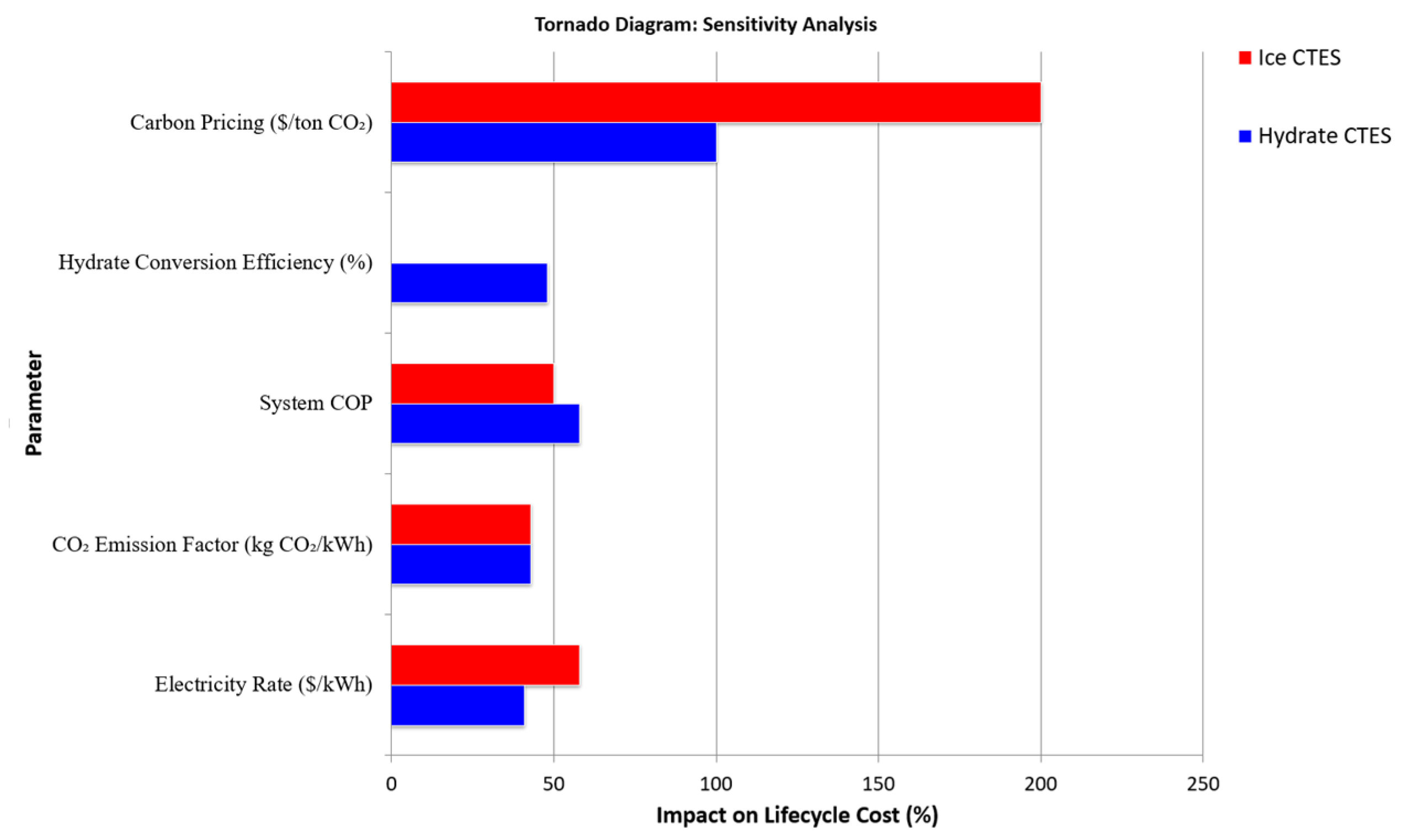
| Parameter | Base Case | Low-End Scenario | High-End Scenario | Impact on Hydrate CTES LCC (%) | Impact on Ice CTES LCC (%) | References |
|---|---|---|---|---|---|---|
| Electricity Rate (USD/kWh) | 0.1276 | 0.08 | 0.18 | ±41% | ±58% | [201] |
| CO2 Emission Factor (kg/kWh) | 0.349 (Hydrate) | 0.198 | 0.37 (Grid) | ±43% | ±43% | [204] |
| System COP (Hydrate CTES/Ice CTES) | 7.03/3.5 | 5.0/3.0 | 8.5/4.0 | +58%/+50% | +50% | [205] |
| Hydrate Conversion Efficiency | 42.7% | 30% | 50% | +48%/N/A | - | [206] |
| Carbon Pricing (USD/ton CO2) | 50 | 30 | 150 | ±100 | ±200% | [207] |
Disclaimer/Publisher’s Note: The statements, opinions and data contained in all publications are solely those of the individual author(s) and contributor(s) and not of MDPI and/or the editor(s). MDPI and/or the editor(s) disclaim responsibility for any injury to people or property resulting from any ideas, methods, instructions or products referred to in the content. |
© 2025 by the authors. Licensee MDPI, Basel, Switzerland. This article is an open access article distributed under the terms and conditions of the Creative Commons Attribution (CC BY) license (https://creativecommons.org/licenses/by/4.0/).
Share and Cite
Annavajjala, S.B.; Van Dam, N.; Mahajan, D.; Kosny, J. A Review of CO2 Clathrate Hydrate Technology: From Lab-Scale Preparation to Cold Thermal Energy Storage Solutions. Energies 2025, 18, 2659. https://doi.org/10.3390/en18102659
Annavajjala SB, Van Dam N, Mahajan D, Kosny J. A Review of CO2 Clathrate Hydrate Technology: From Lab-Scale Preparation to Cold Thermal Energy Storage Solutions. Energies. 2025; 18(10):2659. https://doi.org/10.3390/en18102659
Chicago/Turabian StyleAnnavajjala, Sai Bhargav, Noah Van Dam, Devinder Mahajan, and Jan Kosny. 2025. "A Review of CO2 Clathrate Hydrate Technology: From Lab-Scale Preparation to Cold Thermal Energy Storage Solutions" Energies 18, no. 10: 2659. https://doi.org/10.3390/en18102659
APA StyleAnnavajjala, S. B., Van Dam, N., Mahajan, D., & Kosny, J. (2025). A Review of CO2 Clathrate Hydrate Technology: From Lab-Scale Preparation to Cold Thermal Energy Storage Solutions. Energies, 18(10), 2659. https://doi.org/10.3390/en18102659