Article

General Response Modes of Cylindrical Thermal Contact Conductance to Bidirectional Heat Flux and Temperature Variations

Institute of Nuclear Physics and Chemistry, China Academy of Engineering Physics, Mianyang 621900, China
*
Author to whom correspondence should be addressed.
Energies 2025, 18(10), 2454; https://doi.org/10.3390/en18102454
Submission received: 19 April 2025 / Revised: 6 May 2025 / Accepted: 7 May 2025 / Published: 10 May 2025
(This article belongs to the Section J1: Heat and Mass Transfer)

Abstract

:
Cylindrical joints serve as critical pathways for heat flow in various applications, including heat pipes, electronic devices, and fin-tube heat exchangers. Despite their significance, research has predominantly focused on flat joints, with limited investigation into cylindrical joints, especially on how cylindrical thermal contact conductance (TCC) changes in response to temperature and heat flux, a feature distinctive to cylindrical joints. This study provides a comprehensive theoretical and numerical investigation of cylindrical TCC behavior across various material combinations and heat flux directions. We identified three response modes for outward heat flux and six for inward heat flux, classified by the relative thermal expansion coefficients and heat flux direction. Notably, under inward heat flux, we discovered a previously unreported phenomenon: two possible contact states occurring at identical interfacial temperature, heat flux, and material conditions, with TCC values differing by more than an order of magnitude. The study covers a wide range of conditions (temperatures from 293 K to 1400 K and heat fluxes from 104 to 106 W/m2), confirming that the identified response patterns are broadly applicable and governed by general principles rather than specific material properties or geometric parameters. These findings provide new insights into cylindrical joint behavior and offer valuable guidelines for optimizing the design and performance of thermal systems involving cylindrical interfaces.

1. Introduction

Cylindrical joints serve as pathways for heat flow in a wide range of applications, such as heat pipes [1,2], plug and ring assemblies [3], electronic devices [4], and fin-tube heat exchangers [5]. The performance of these applications is heavily dependent on the thermal contact conductance (TCC) of the joints. Unlike flat joints, the TCC of cylindrical joints is inherently more complex because the contact pressure—a major influencing factor for TCC—is heavily influenced by the thermal expansion of the cylinders. This expansion varies dynamically with temperature, heat flux, and material properties. As a result, understanding how cylindrical TCC responds to changes in these parameters is crucial for optimizing heat transfer performance in scenarios where temperature and heat flux can fluctuate significantly during operation, such as in heat-pipe nuclear reactors [6], where both temperature and heat flux can be extremely high. In the Kilopower reactor, heat pipes operate with a heat flux at the evaporator over 10 4 W/m2 [7]. In the work of Merrigan et al. [8] at Los Alamos National Laboratory, a lithium heat pipe was developed for a space nuclear reactor at over 1400 K with a heat flux of 1.5 × 10 6 W/m2 at the heat-pipe evaporator. An erroneous estimation of the TCC can lead to temperature variations of 100 K or more, causing poor system performance and even reactor core meltdown.
Despite its critical importance, the response of cylindrical TCC to temperature and heat flux remains underexplored in the literature. Reviews from the 1990s indicate that only about 5% of TCC publications addressed cylindrical joints [9], and most research has focused on flat joints. For instance, Kumar and Tariq [10] analyzed the effects of contact nature on transient thermal contact conductance, showing that the contact pressure significantly influences thermal behavior in transient states. Rosochowska et al. [11] measured thermal contact conductance for various materials, providing a database of TCC values for different material interfaces. Singhal et al. [12] developed an experimentally validated thermo-mechanical model for TCC, showing how thermal expansion and contact pressure interact to affect heat transfer across material pairs. Tariq and Asif [13] experimentally investigated TCC for nominally flat metallic contacts, revealing how material properties like thermal conductivity and surface roughness impact the heat transfer at the interface. More recent works have contributed to advanced modeling approaches and a deeper understanding of interfacial behaviors, including a few regarding cylindrical joints, but the specific response patterns of cylindrical TCC to temperature and heat flux have been largely unexamined. For instance, Sun et al. [14] developed a fractal model to predict TCC for spherical joint surfaces considering friction. Kumar et al. [15] applied FEM-based computational techniques to predict TCC, offering methods that can be extended to cylindrical systems. Yang et al. [16] modeled thermal and force interactions in machining processes, providing insights that could be applied to cylindrical contacts. Brazhenko et al. [17] examined the thermal performance of multilayer walls in aerospace structures.
Additionally, there is a lack of experimental data to provide a comprehensive reference. Due to time and cost constraints, experimental studies typically involve only one or two material combinations, and the temperature or heat flux range is narrow. For example, Kumar et al. [18] investigated thermal contact conductance for cylindrical and spherical contacts, focusing on the effect of contact mechanics on heat transfer. Tio and Chuan [19] studied the thermal resistance of two solids in contact through a cylindrical joint, providing insights into the thermal behavior of cylindrical interfaces. Liu et al. [20] examined thermal contact conductance between rollers and bearing rings, exploring the impact of material properties and geometry on heat transfer in bearing systems. Tafazzoli Aghvami et al. [21] estimated the steady-state thermal contact conductance between a sliding disk and a stationary cylinder, investigating how similar and dissimilar materials affect TCC under isothermally heated conditions. Existing research also predominantly focuses on radial-outward heat flow, which assumes that heat flows outwards from an inner source. However, there are critical cases, such as the hot side of a heat pipe in a nuclear reactor, where heat flows inward, and TCC is a significant issue. Changing the direction of heat flow alters the relative thermal expansion significantly, potentially leading to very different TCC response patterns.
Madhusudana’s work [22,23,24] is the most relevant to this study, investigating steel-aluminum cylindrical contact under a wide range of temperatures and heat fluxes with radial-outward heat flow. Their model showed that TCC generally increases monotonically with heat flux but may either increase or decrease with temperature, depending on which material is on the outside. However, whether this response pattern applies to other material combinations or inward heat flow remains unexplored.
This study aims to fill these gaps by investigating how cylindrical TCC responds to temperature and heat flux across a broad range of materials and both outward and inward heat flow. Given the significant gap in the literature, this work focuses on the qualitative generalization of the response patterns rather than quantitative predictions. Using theoretical and numerical methods, we overcome the limitations of experimental studies to cover a wide range of temperatures (from 293 to 1400 K) and heat fluxes (from 10 4 to 10 6 W/m2). Specifically, we numerically solve the thermo-mechanical governing equations for TCC responses using a 2D model of concentric hollow cylinders with typical material sets of stainless steel and molybdenum, and then analyze theoretical equations to generalize these findings across various material combinations.
The remainder of this paper is organized as follows: Section 2 presents the theoretical framework and numerical methods. Section 3 discusses the results of the numerical simulations and theoretical analyses, highlighting key response patterns of cylindrical TCC. Finally, Section 4 concludes with a summary of the contributions and future research directions.

2. Materials and Methods
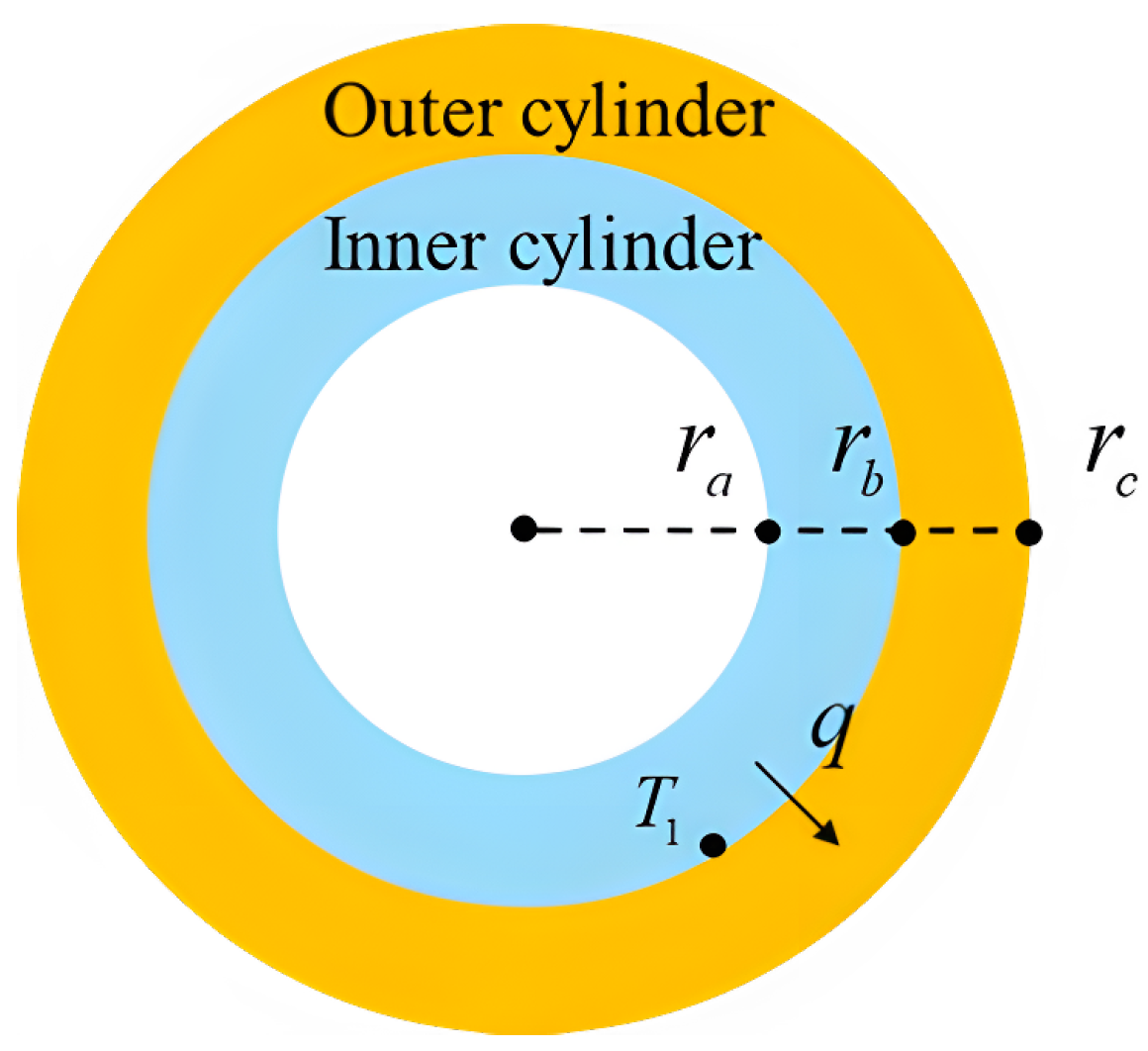
2.1. Physical Model

As this study focuses on the qualitative generalization of the response patterns, we choose a 2D model with circumferentially uniform boundary conditions, which significantly reduces computational costs, enabling a much broader range of cases to be investigated. In addition, in scenarios where the cross-sectional scale is small compared to the length of the cylinder (such as in heat-pipe reactors), and where strong non-uniformities are not expected in the axial direction, a 2D model can effectively represent the behavior of a 3D cylindrical system. In cases with strong axial non-uniformities, there may be additional complexities in the TCC response. This is an area we intend to explore in future work.
The model is depicted in Figure 1. It is a cross-section of two concentric hollow cylinders with radii at the innermost surface, at the outer surface of the inner cylinder, and at the outermost surface being r a , r b , and r c , respectively. The boundaries of both cylinders are free of restrictions. Effects in the axial direction are neglected, which is reasonable when the scale of the cross-section is small compared to the cylinder length, as in heat-pipe reactors.
Initially, the system has a uniform temperature of T 0 and no heat flux. The interfacial gap between the two cylinders is u 0 , which can be positive (gap) or negative (degree of fit). At the working state, a total heat of Q is transferred radially inward or outward, uniformly distributed in the circumferential direction, with the heat flux at the interface being q, and the temperature at the outer surface of the inner cylinder is raised to T 1 , referred to as the interfacial temperature. The corresponding TCC at the cylindrical interface is h s , which depends on the temperature, heat flux, and material combinations. Details of solving for h s are introduced in the next section.

2.2. Governing Equations
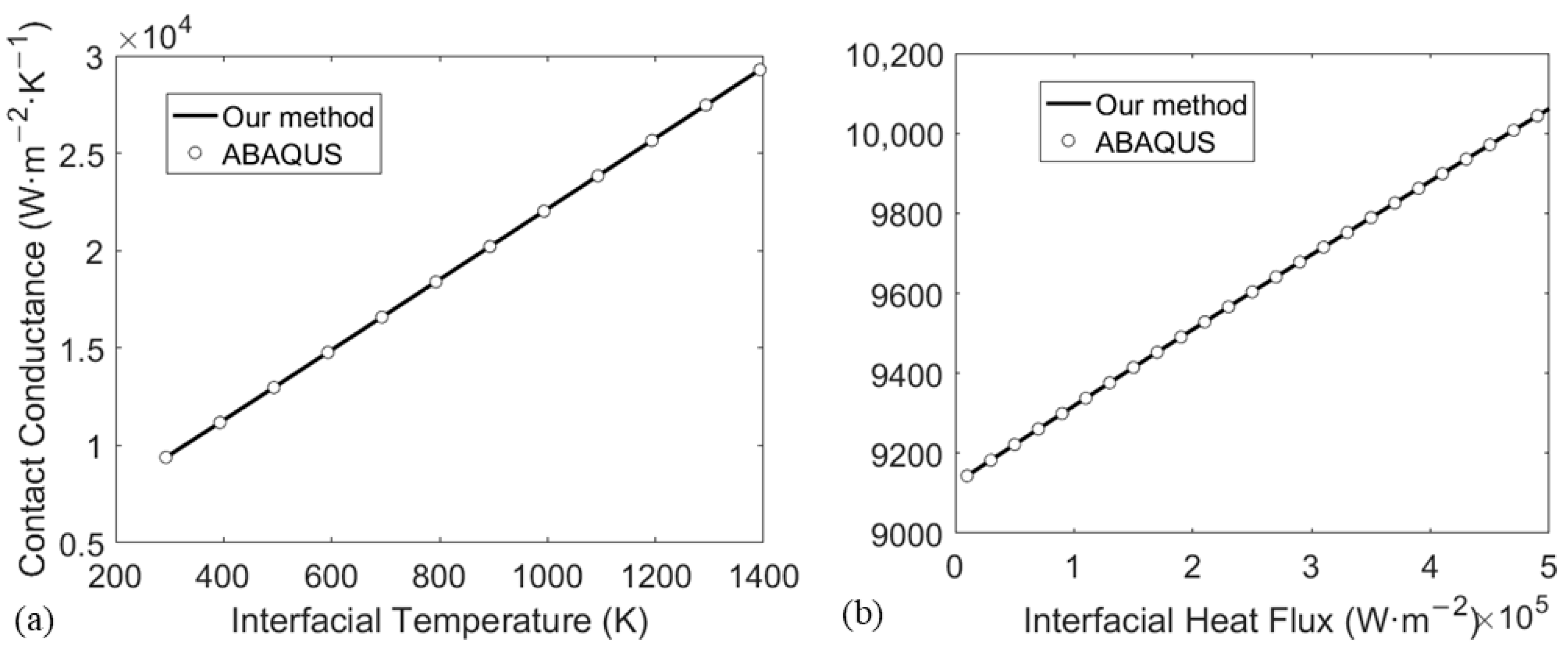
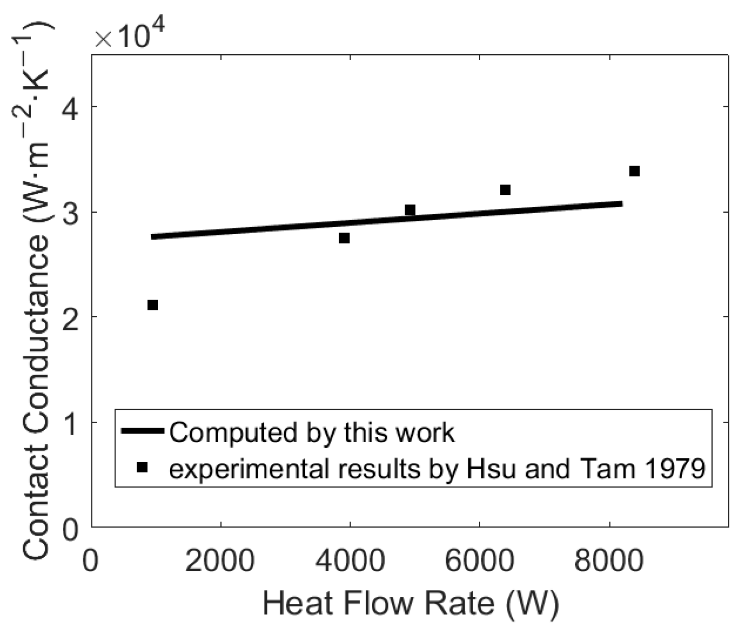
While quantitatively accurate equations for h s are difficult to obtain, most empirical correlations between h s and relevant physical factors share similar forms, indicating a consensus on qualitative relations. Given the qualitative focus of this study, we use one of the most common empirical expressions for h s [25,26,27]:
h s = C tan θ m k m σ m p H n ,
where C and n are empirical coefficients usually set close to 1, θ m the mean absolute slope of surface, k m the harmonic mean of thermal conductivities of the composite cylinders, σ m the effective surface roughness, p the interfacial pressure, and H the hardness of the softer material. For any given material combination, only p may change with temperature or heat flux, which changes the state of cylindrical thermal expansion. Therefore, solving for h s requires solving the thermal-mechanical steady state of the composite cylinders.
First, consider the pressure-induced deformation. Denote the pressure-induced radial displacement of the inner and outer cylinders at the interface by u i p and u o p , the following equations can be derived [28,29,30]:
u i p = r b p E i r b 2 + r a 2 r b 2 r a 2 v i ,
u o p = r b p E o r C 2 + r b 2 r C 2 r b 2 + v o ,
where E i and E o are the elastic moduli, and v i and v o are the Poisson’s ratio of the inner and outer cylinders, respectively.
The cylinders will also deform from thermal expansion. Denote the thermal-induced radial displacement of the inner and outer cylinders at the interface by u i t and u o t . They can be related to the temperature field T ( r ) by [28,29,30]:
u i t = ( 1 + v i ) α ( 2 1 + v i r b ) 1 r b 2 r a 2 r a r b ( T T 0 ) r d r ,
u o t = ( 1 + v o ) α ( 2 1 + v 0 r b ) 1 r c 2 r b 2 r b r c ( T T 0 ) r d r .
Within each cylinder, the temperature field is given by the steady-state heat equation:
k i 1 r d d r ( r d T d r ) = 0 ,
k o 1 r d d r ( r d T d r ) = 0 .
The temperature field has a jump of Δ T across the interface, determined by h s and radiation conductance h r :
h s + h r = q Δ T ,
h r = σ ( T 1 + Δ T ) 4 T 1 4 1 / ε i + 1 / ε o 1 1 Δ T ,
where q is the heat flux at the interface, σ m the Stefan-Boltzmann constant, and ε i and ε o the emissivity of the composite cylinders. Convection is neglected as the interfacial gap is small. For simplicity, theoretical analysis also ignores the conduction of the gas gap, which applies directly to high-temperature heat-pipe reactors that often operate in a vacuum. For a characteristic length of 10 μ m and a pressure of 1 × 10³ Pa, the Knudsen number is approximately 106 at room temperature. This indicates a highly rarefied flow, making it reasonable to neglect convection in this case. Inclusion of gas gap conduction does not change our qualitative conclusions, as shown in the discussion section.
At equilibrium, the cylinders are in contact, so the interfacial gap should be zero:
( u o p u i p ) + ( u o t u i t ) + u 0 = 0 .
If the cylinders lose contact at any point, the equations will not provide a valid solution for TCC. While a state of lost contact is physically possible, the TCC would be so low in such cases that analyzing it becomes irrelevant for most practical applications, and thus it is not investigated in this work.
Combining Equations (1)–(10), we can numerically solve for h s given any interfacial temperature T 1 , interfacial heat flux q, and material combinations. Please note that since we solve for h s given different values of temperature and interfacial heat flux independently, without considering a dynamic process where temperature or interfacial heat flux changes over time, all results represent the steady-state TCC. This does not imply that q and T 1 are physically independent—rather, it is a mathematical treatment for the purpose of solving for h s . The findings in our work are primarily related to differential thermal expansion. Therefore, the applicability of our results to transient processes depends on how quickly the steady or quasi-steady temperature field is established during such processes. Details of the computation are introduced in Section 2.4.

2.3. Benchmark

Our method is benchmarked against ABAQUS 2023. For a stainless steel/molybdenum composite cylinder under outward heat flux, h s is computed at varying interfacial temperatures T 1 and interfacial heat fluxes q. The parameters are the same as those described in Section 2.4. Since ABAQUS does not have a built-in accurate computation method for contact conductance, Equation (1) is also adopted in our ABAQUS simulation. Thus, the benchmark essentially validates our coupled method without quantitatively validating Equation (1). Given the qualitative focus of this work, such benchmark is sufficient for ensuring that our method accurately captures the general response patterns: Equation (1) is a commonly used model, and the choice of parameters in Equation (1) and even the specific model do not significantly impact the qualitative results, as will be discussed in Section 3.2.
The simulation is performed iteratively. An initial TCC is assumed at the interface, and the contact pressure is obtained given T 1 and q. The simulation is then repeated with the updated TCC until the solved pressure and TCC match Equation (1). A mesh independence study is presented in Figure 2, at q = 2 × 10 5 W/m2 and T 1 = 300 K under outward heat flow. Based on the result, a mesh size of 0.5 mm is adopted for all following ABAQUS simulations.
Results are illustrated in Figure 3, showing good agreement between our method and numerical simulation, making our method valid for a qualitative study.
Although quantitative accuracy of the numerical method is not essential for this work, we add a quantitative comparison against one experiment by Hsu and Tam [10], in Figure 4. The relevant parameters are shown in Table 1.

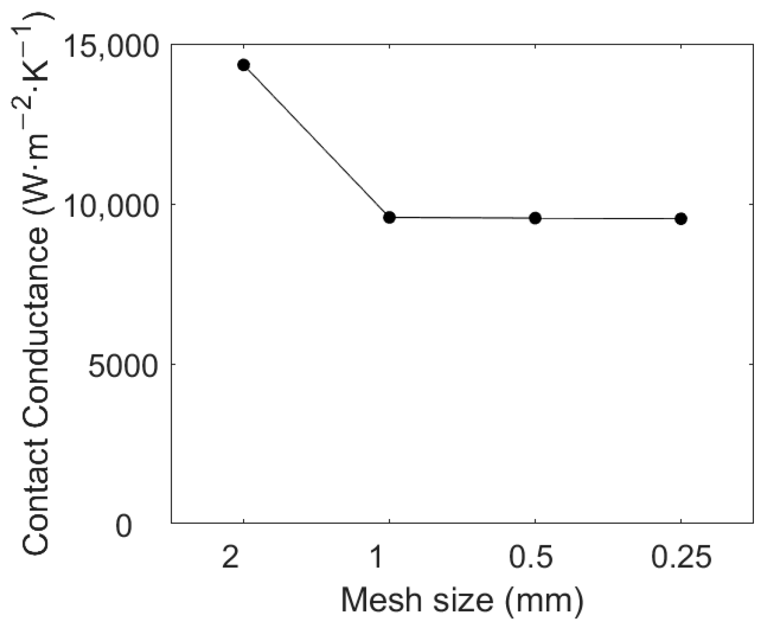
2.4. Computation Parameters

The numerical method, although much cheaper than experimentation, cannot directly cover all possible cases. Therefore, we need to choose representative ones. This work focuses on the general rules with varying temperature, heat flux, and material properties, requiring a broad range of temperature and heat flux and sufficient material combinations.
In this study, the cylinder materials are either stainless steel (SS) or Molybdenum (Mo), resulting in three material combinations: SS-Mo, Mo-SS, and Mo-Mo, with the first material being the inner cylinder. These materials are common in heat-pipe reactors, and two materials will be proven sufficient to illustrate the qualitative patterns. Relevant material properties are presented in Table 2. All thermo-physical properties are assumed to be independent of temperature, and the impact of temperature-dependent thermo-physical properties will be discussed in Section 3.1.
The absolute slope of the surface is set to be 5°, and the surface roughness is 1 × 10⁻⁶ m for both materials. Other parameters, including geometric parameters and empirical coefficients, are the same for all material combinations and chosen as follows: r a = 8.5 × 10 3 m, r b = 9.5 × 10 3 m, r c = 13.5 × 10 3 m, u 0 = 5 × 10 5 m, C = 0.1 and n = 1. The values are based on typical heat-pipe reactors, and we will demonstrate that variations in these parameters do not change the qualitative patterns.
In summary, we perform six sets of numerical computation for h s : three material combinations (SS-Mo, Mo-SS, Mo-Mo) multiplied by two heat flow directions (outward and inward). For each set, the range of interfacial temperature T 1 is from 293 to 1400 K, and the range of interfacial heat flux q is from 10 4 to 10 6 W/m2, covering most high heat flux cases in practical applications. The temperature range here has exceeded the safe limits for stainless steel but is still within the safe limits for molybdenum. For the sake of simplicity, we have chosen to use the same range for both. After computing h s for these specific cases, we carry out a theoretical analysis to show that their patterns are representative.

3. Results and Discussion

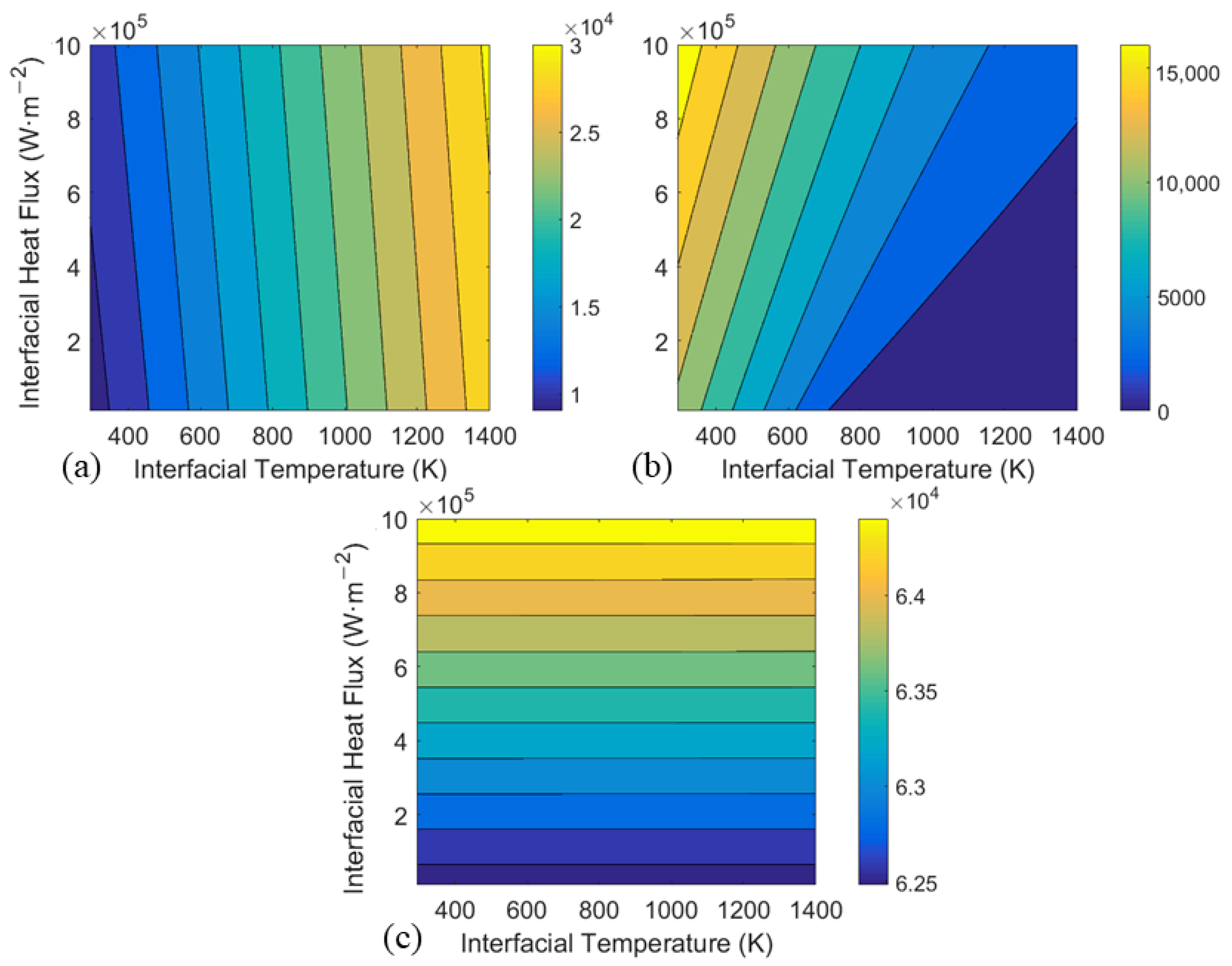
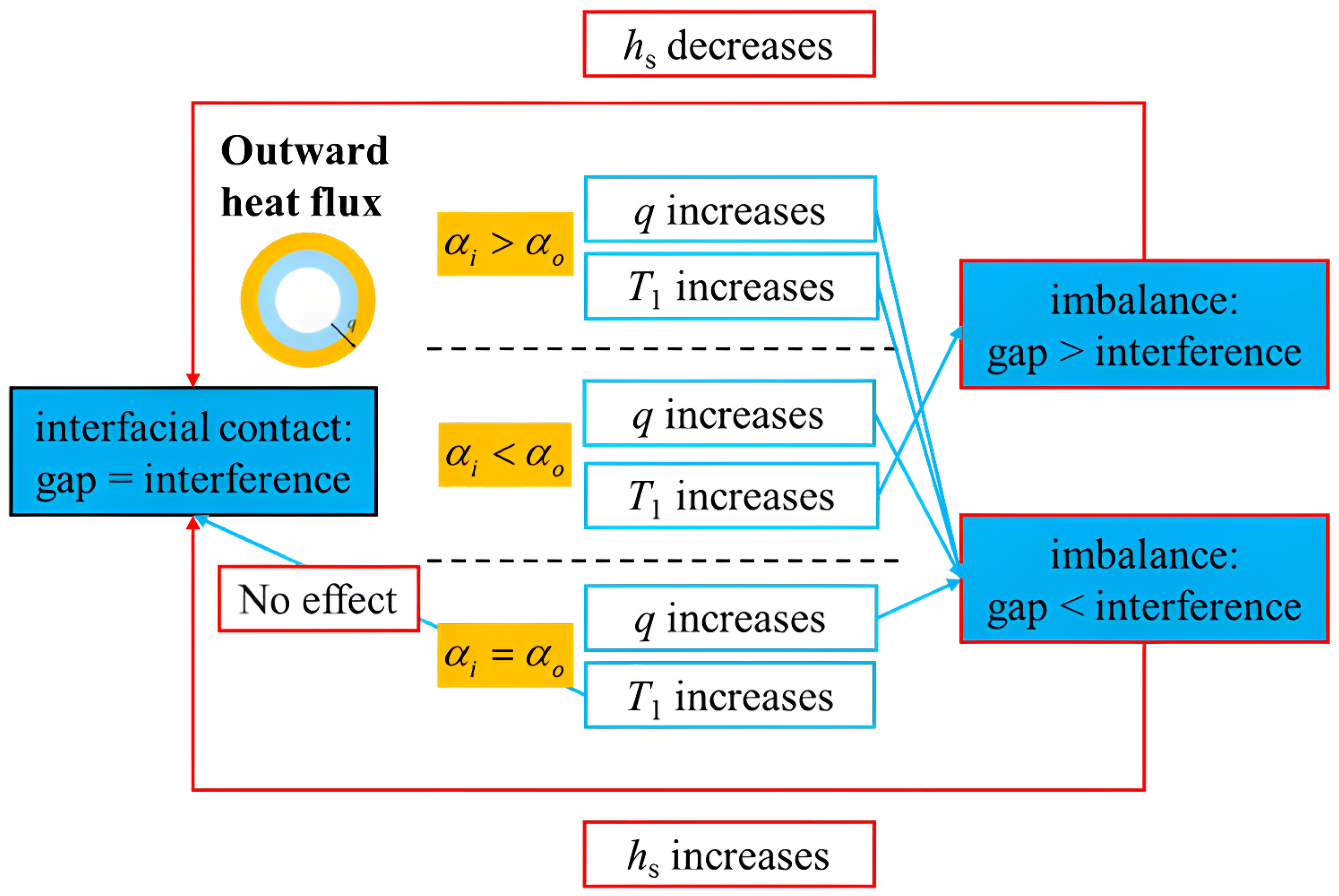
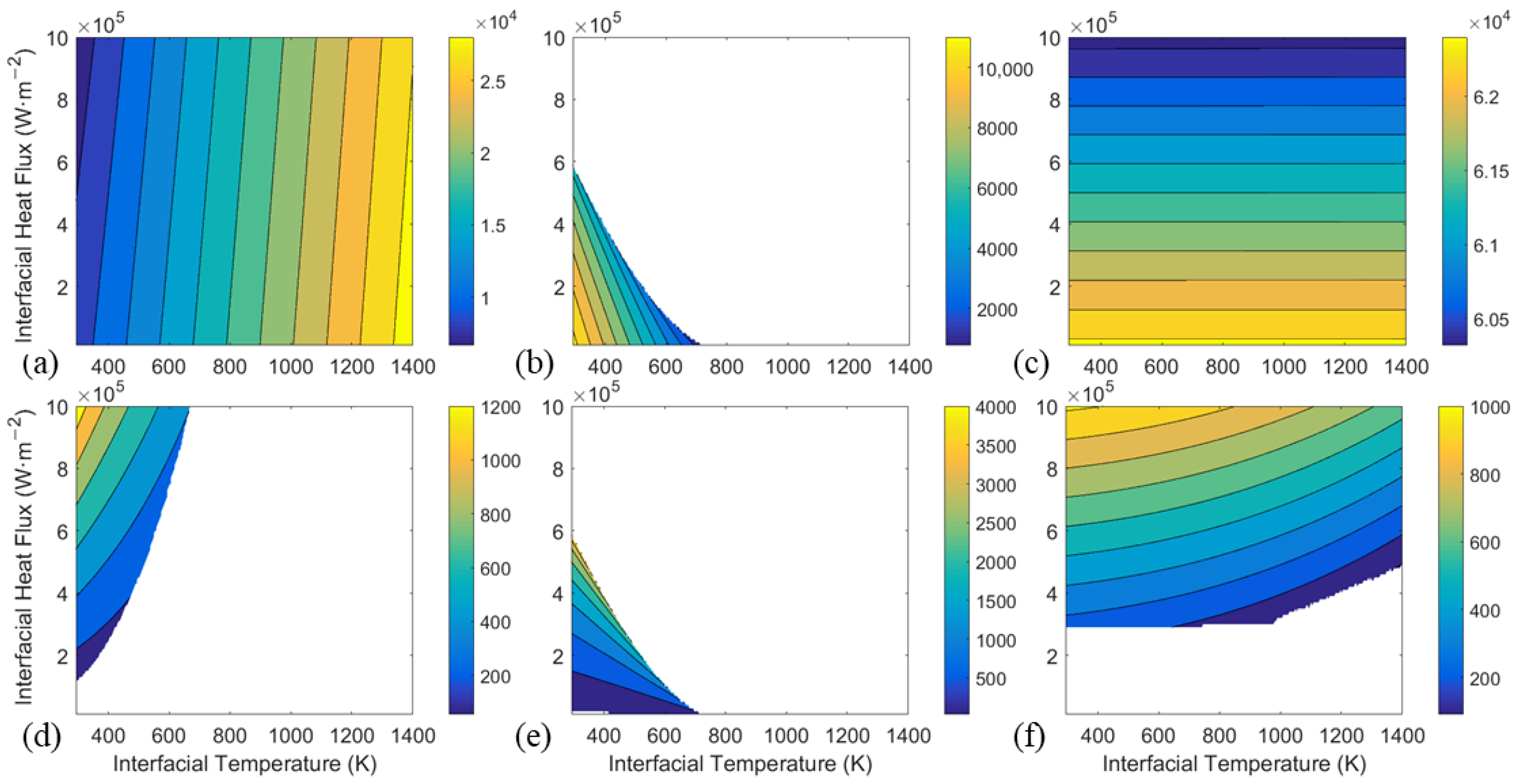
3.1. Outward Heat Flux: Three Representative Response Modes

First, we investigate cases with radial-outward heat flow. Figure 5 illustrates the contour of computed thermal contact conductance h s against interfacial temperature T 1 and heat flux q for SS-Mo, Mo-SS, and Mo-Mo composite cylinders. Figure 6 is the corresponding contour of the computed interfacial temperature jump. For each material combination, TCC is monotonic with temperature and heat flux: it always increases with heat flux, whereas with temperature, it may increase or decrease depending on the specific material combination. We will show that these three contours computed from specific sets of parameters actually represent three general response modes for arbitrary material combinations, as long as heat flows outwards. Please note that since h s is proportional to p n in Equation (1), the contours of h s also reflect the patterns of contact pressure.
From the governing equations in Section 2.2, we derive the following equation for h s :
1 E h s r b α o q 1 h s + h r = q [ R 1 α i k i + ( R 2 + R 3 ) α o k o ] + ( T 1 T 0 ) r b ( α i α o ) + u 0 ,
where
1 E = r b [ 1 E 0 ( r c 2 + r b 2 r c 2 r b 2 + v o ) + 1 E i ( r b 2 + r a 2 r b 2 r a 2 v i ) ] / ( C tan θ m k m σ m H ) ,
R 1 = 1 2 r a 2 r b 2 r a 2 log r b r a r b 2 2 , R 2 = 1 2 r b 2 r c 2 r b 2 log r c r b r b 2 2 , R 3 = log r c r b r b 2 2 .
The right side of Equation (11) can be rewritten in a simpler form:
1 E h s r b α o q 1 h s + h r = q · C q + T 1 · C T + U 0 ,
where
C q = R 1 α i k i + ( R 2 + R 3 ) α o k o , C T = r b ( α i α o ) , U 0 = T 0 r b ( α i α o ) + u 0 .
Each term in Equation (14) has the dimension of displacement and can be understood as the interfacial gap or interference (negative gap) from some source: h s / E is the pressure-induced gap, r b α o q / ( h s + h r ) , q · C q , T 1 · C T are all part of the thermal-induced interference, which can be further defined as the interference due to the interfacial temperature jump, the interference due to the temperature gradient within each cylinder, and the interference due to the rise of the average temperature, respectively. U 0 is the initial interference. Therefore, the balance of Equation (14) indicates that the interfacial gap is zero, meaning the two cylinders are in contact. The physical image is that the pressure-induced gap cancels out the interfacial interference due to thermal expansion and/or initial degree of fit.
Without assuming anything about the material properties or geometric parameters. It can be proven by simple mathematical analysis that E > 0 , R 1 > 0 , R 2 > 0 , R 3 > R 2 , regardless of the parameter values, as long as they are physical (i.e., r c > r b > r a > 0 , E > 0 , k > 0 , etc.). Therefore, it can be further deduced that C q > 0 , while C T has the same sign as α i α o , regardless of the parameter values.
Based on the general inequalities and Equation (14), we can do a theoretical analysis when material combinations are arbitrary. First, consider how the change in q, T 1 , and h s each affects the interfacial gap/interference. When q increases, both the interference due to interfacial temperature jump r b α o q / ( h s + h r ) and the interference due to temperature gradient within each cylinder q · C q increase, leading to a total increase in the interfacial interference. When T 1 increases, depending on the sign of α i α o , the interference due to the rise of the average temperature T 1 · C T may increase ( α i > α o ), decrease ( α i < α o ), or remain unchanged ( α i = α o ). Here, the impact of changing q and T 1 on h r is ignored in the analysis, as h r is very small compared to h s in our computed results. When h s increases, the pressure-induce gap h s / E increases, and the interference due to interfacial temperature jump r b α o q / ( h s + h r ) decreases, leading to a total increase in the interfacial gap.
The response of h s to q and T 1 should always cancel out their effects on the interfacial gap/interference to rebalance Equation (14) and maintain the cylinders in contact, as conceptually shown in Figure 7. Therefore, h s always increases with q, and with T 1 , it has three response modes depending on the sign of α i α o . These deductions agree with the computed results in Figure 5 for the SS-Mo, Mo-SS, and Mo-Mo systems. Since there are only three possibilities for the sign of α i α o , three response modes are sufficient to represent the general response patterns under radially outward heat flow. Furthermore, when h s is big enough, the term r b α o q / ( h s + h r ) becomes so small that it can be neglected, and the response of h s to q, T 1 becomes linear, as suggested by Equation (14) and shown in Figure 6.
Intuitively but not rigorously, we can understand the general response modes as follows: the expansion of the outer cylinder moves it away from the interface, loosening the contact and thus decreasing h s , while the expansion of the inner cylinder increases h s for the opposite reason. When q increases, the temperature gradient along the heat flow path increases, and because heat flows outward, the inner cylinder will experience a greater temperature rise. Therefore, the net effect is the expansion of the inner cylinder, leading to larger h s . When T 1 increases, the cylinder with the larger expansion coefficient will dominate the net effect. For example, when α i is larger, the net effect is the expansion of the inner cylinder, and h s increases.
We conclude this section by discussing how the inclusion of gas gap or temperature-dependent thermo-physical properties affects the response mode. With gas gap conductance h g , the r b α o q / ( h s + h r ) term in Equation (14) changes to r b α o q / ( h s + h r + h g ) . In many previous works [23,24], the gas gap width is the only variable that may change h g when q and T 1 change. For two surfaces in contact, the microscopic gap width is often set to be constant, depending only on the surface properties. A resulting constant h g surely will not alter the general response modes regardless of the heat flow direction. In addition, from the results obtained in our study (including those in Section 3.2 under inward heat flow), when the temperature changes from 293 K to 1400 K, TCC typically changes by over 200% or −80%, except when the cylinders are made of the same material, where the impact of differential thermal expansion is minimized. While more advanced models that include the effects of temperature on gas gap conductance exist, the variance in these models is relatively insignificant compared to the effect of differential thermal expansion in many cases. Therefore, for the simplicity of computation and analysis, and given the qualitative focus of this work, the gas gap conductance is not considered. In terms of temperature-dependent thermo-physical properties, sensitivity analyses at q = 1 × 10 5 W/m2 regarding individual thermo-physical parameters in Figure 8 show that in most cases, changes in these parameters (such as doubling or halving their values) cause the TCC to remain within a range of approximately twice or half of the initial TCC. Few thermo-physical properties undergo changes in magnitude similar to those of the TCC over this temperature range, so the qualitative response patterns are unaffected in these cases. Moreover, while certain cases could see an impact from temperature-dependent properties—such as when materials have very similar or identical expansion coefficients (minimizing the differential thermal expansion) or when specific parameters change dramatically with temperature—these effects are material-specific. For instance, the thermal conductivity may increase with temperature for one material but decrease for another. This study intentionally excludes such cases to focus on general response patterns. Our approach can be considered to be analyzing response patterns that are decoupled from temperature-dependent properties, allowing for generalization. These patterns are directly applicable to many cases where the impact of temperature-dependent properties is not significant. When the impact is substantial, material-specific effects can be incorporated to yield a more complete picture.

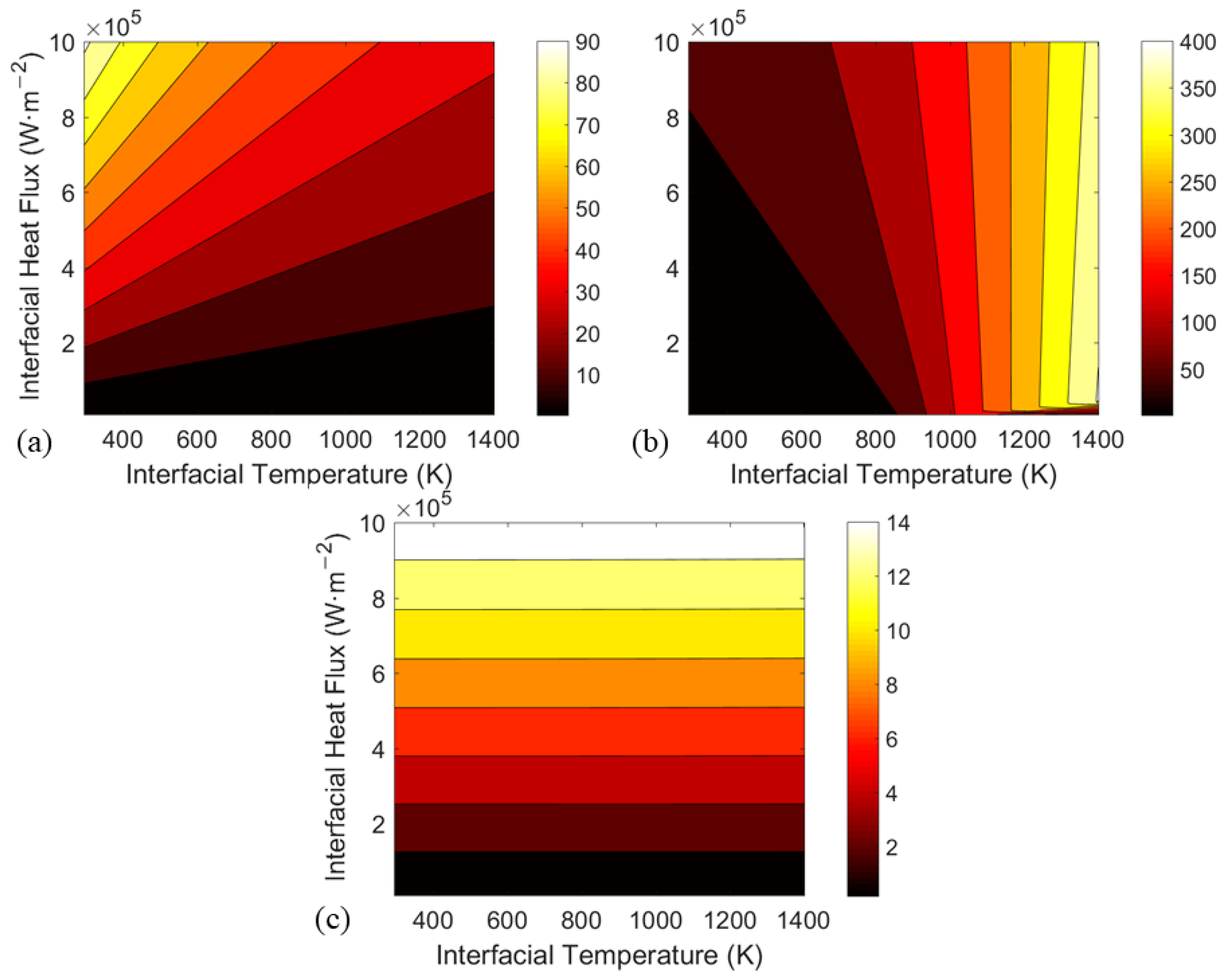
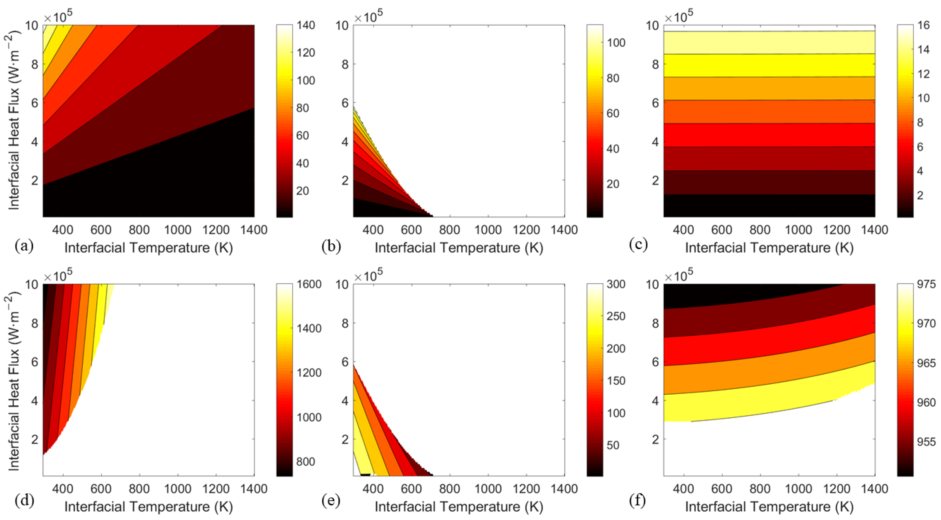
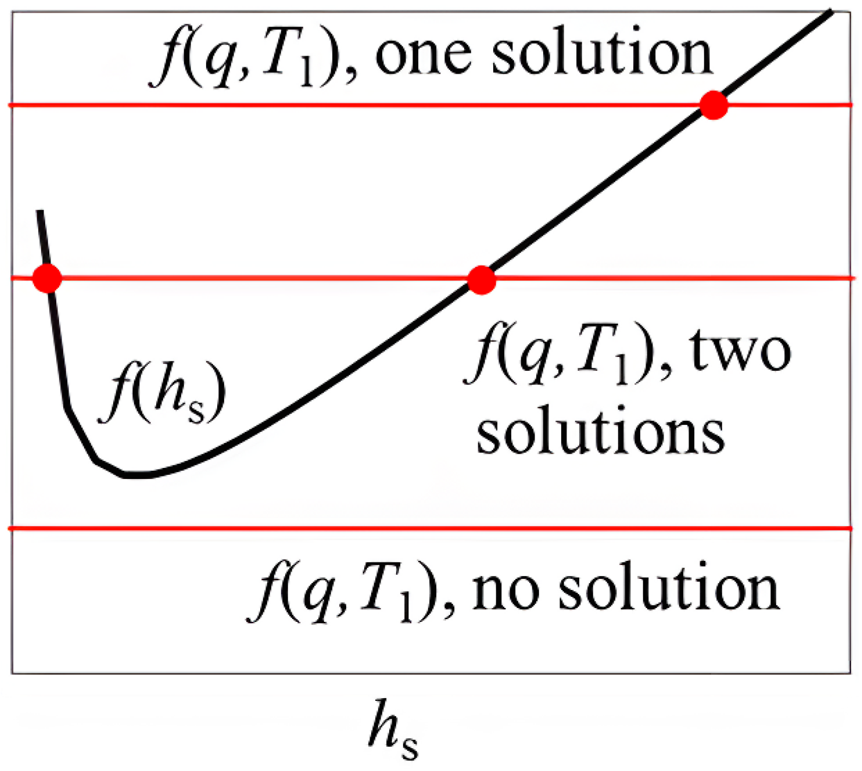
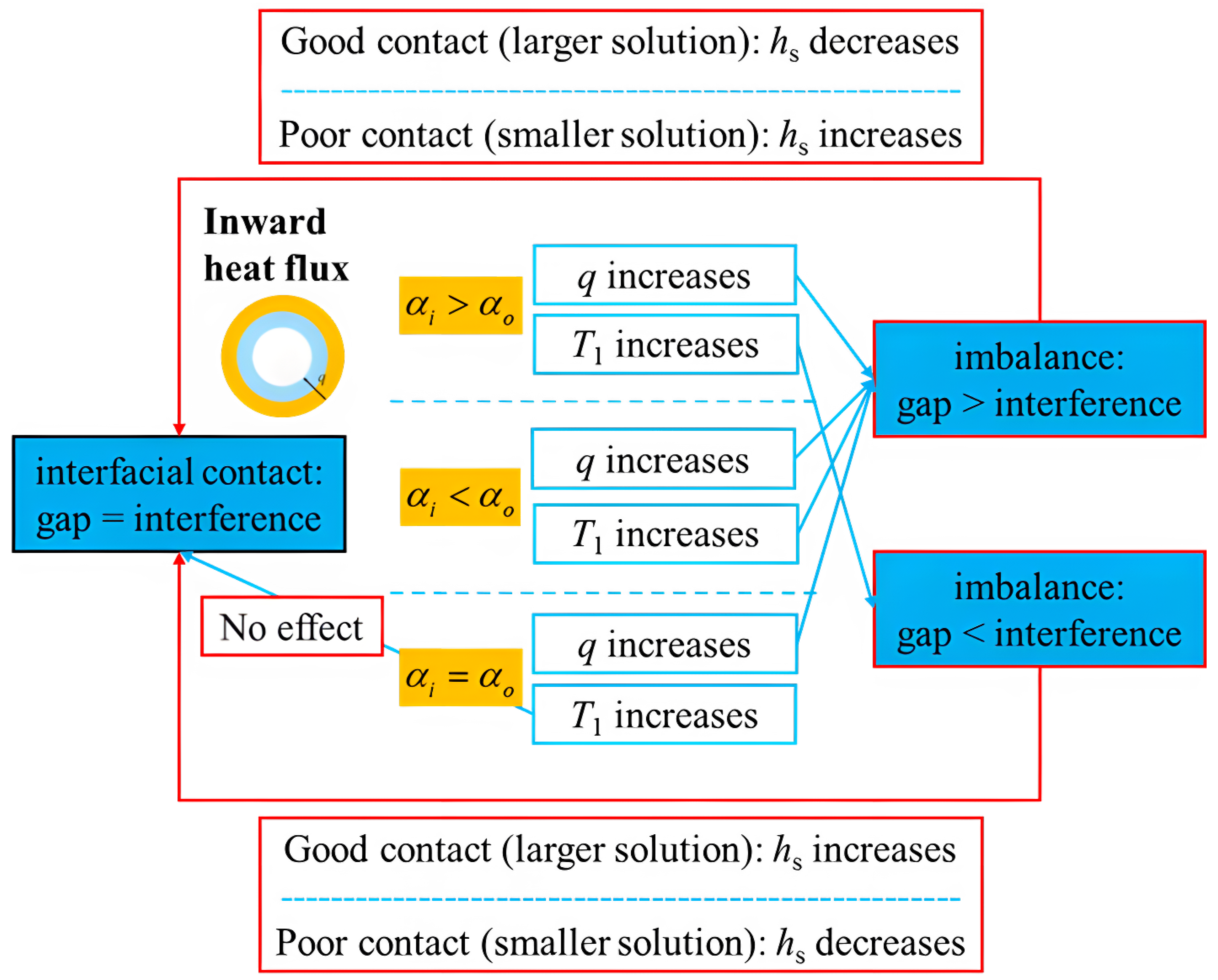
3.2. Inward Heat Flux: Six Representative Response Modes and Two Coexistent Solutions

Next, we examine cases with radial-inward heat flow. Figure 9 shows the contour of computed thermal contact conductance h s , against interfacial temperature T 1 and heat flux q for SS-Mo, Mo-SS, and Mo-Mo composite cylinders, with inward heat flux. Figure 10 is the corresponding contour of the interfacial temperature jump. The blank parts on the contours indicate that the cylinders have lost contact. There are now six contours instead of three, two for each material combination, meaning that two possible solutions of h s coexist for the same interfacial q and T 1 . Here, we first investigate the reason for these coexistent solutions and then delve into the details of the response modes.
As with Section 3.1, the following simplified equation of h s can be derived under inward heat flux:
1 E h s + r b α o q 1 h s + h r = q · C q + T 1 · C T + U 0 .
The only difference between this equation and the previous one for outward heat flux is the reversed sign of r b α o q / ( h s + h r ) and q · C q . This alone can mathematically explain the additional solution of h s . Let us refer to the left side of the equation as f ( h s ) , and the right side as f ( q , T 1 ) . For fixed q and T 1 , f ( h s ) always increases monotonically with h s in the case of outward heat flux, but under inward heat flux, f ( h s ) first decreases to a minimum value and then increases as h s goes from zero to infinity. This non-monotonic trend allows for at most two coexistent solutions, as illustrated in Figure 11 with the black curve representing f ( h s ) and the red lines representing f ( q , T 1 ) .
The physical explanation is as follows: when heat flows outward, a larger h s increases the pressure-induce gap h s / E and decreases the interference due to interfacial temperature jump r b α o q / ( h s + h r ) , preventing another solution for h s that keeps the cylinders in contact. However, with inward heat flow, a larger h s still increases the gap h s / E but also decreases the gap r b α o q / ( h s + h r ) since its sign is reversed, allowing for another solution of h s when these two parts cancel out. This feature of two coexistent solutions is unique to systems with inward heat flow, stemming from the asymmetry between the thermal expansion of the inner and outer cylinders: the expansion of the inner cylinder enhances the interfacial contact, while that of the outer cylinder does the opposite. When h s is large enough that the interfacial temperature jump r b α o q / ( h s + h r ) can be neglected, the response patterns between inward and outward heat flux are closely related: the same to T 1 , the opposite to q since heat flux is reserved. When h s is small, the asymmetry allows for a “smaller solution” only under inward heat flux.
Now, we examine the response modes in more detail. First, consider how the change in q, T 1 , and h s each affects the interfacial gap/interference. When q increases, both the gap due to interfacial temperature jump r b α o q / ( h s + h r ) and the gap due to temperature gradient within each cylinder q · C q increase, leading to a total increase in the interfacial gap, the opposite of what happens when heat flows outward. The effects of changing T 1 , on the other hand, are identical to those when heat flows outward. Increasing h s has two opposing effects: increasing the pressure-induce gap h s / E and decreasing the gap due to interfacial temperature jump r b α o q / ( h s + h r ) . The combined effect depends on which term dominates. Since h s / E increases with h s but r b α o q / ( h s + h r ) decreases, among the two coexistent solutions of h s , the larger solution must be dominated by h s / E and the smaller solution dominated by r b α o q / ( h s + h r ) . Therefore, when the system is in the state of the larger solution, increasing h s leads to a larger interfacial gap, and the opposite is true for the smaller solution. Considering the need to rebalance the equation and maintain contact, the six response modes can be conceptually drawn in Figure 12, which agrees with the computed results for the SS-Mo, Mo-SS, and Mo-Mo systems.
Nothing is assumed here about the material properties, surface properties, or geometric parameters. The six response modes arise from the three possibilities of the sign of α i α o and the different behaviors of the two coexistent solutions for h s . The six computed contours for h s in Figure 9 are sufficient to represent the general response patterns under radially inward heat flow.
The two solutions of h s can be considered to correspond to two different contacting states: the larger solution indicates good interfacial contact, while the smaller solution indicates poor contact. Under good contact, the interfacial temperature drop Δ T is small, and the heat flux is primarily due to the large conductance h s . Under poor contact, a higher heat flux is achieved mainly by the large interfacial temperature drop Δ T , leading to a very high temperature of the outer cylinder (with T 1 being the temperature at the inner side of the interface). Practically, this is usually undesirable, as it may lead to core meltdown in a heat-pipe reactor and should be avoided. Intuitively, a faster heating rate is more likely to cause a poor contact state, as the heat flux across the interface is limited, and most of the heat will contribute to raising the temperature of the source. A more thorough investigation, supported by experimental data, is needed to confirm this in future work.
We conclude this section by discussing the applicability of the qualitative response patterns. As shown in the theoretical analysis above, obtaining these qualitative patterns does not require assumptions about material properties, surface properties, or geometric parameters, which greatly enhances the generality of our findings. Furthermore, by analyzing Equation (14) for outward heat flow and Equation (16) for inward heat flow—key equations in our analysis—it becomes apparent that the impact of most parts of the model is encapsulated in the coefficients E , and if these parameters do not vary significantly with temperature or heat flux, they will not alter the qualitative patterns. Therefore, any model that considers contact pressure as one main positive influencing factor ( h s proportional to p n ) can yield similar results. This makes the specific choice of model less critical for the overall objectives of this study. However, this does suggest a limitation of this work: if contact pressure is no longer a major positive influencing factor of TCC—such as when gas gap conduction or radiation dominates, or for materials that respond differently to pressure—then the qualitative patterns no longer apply.

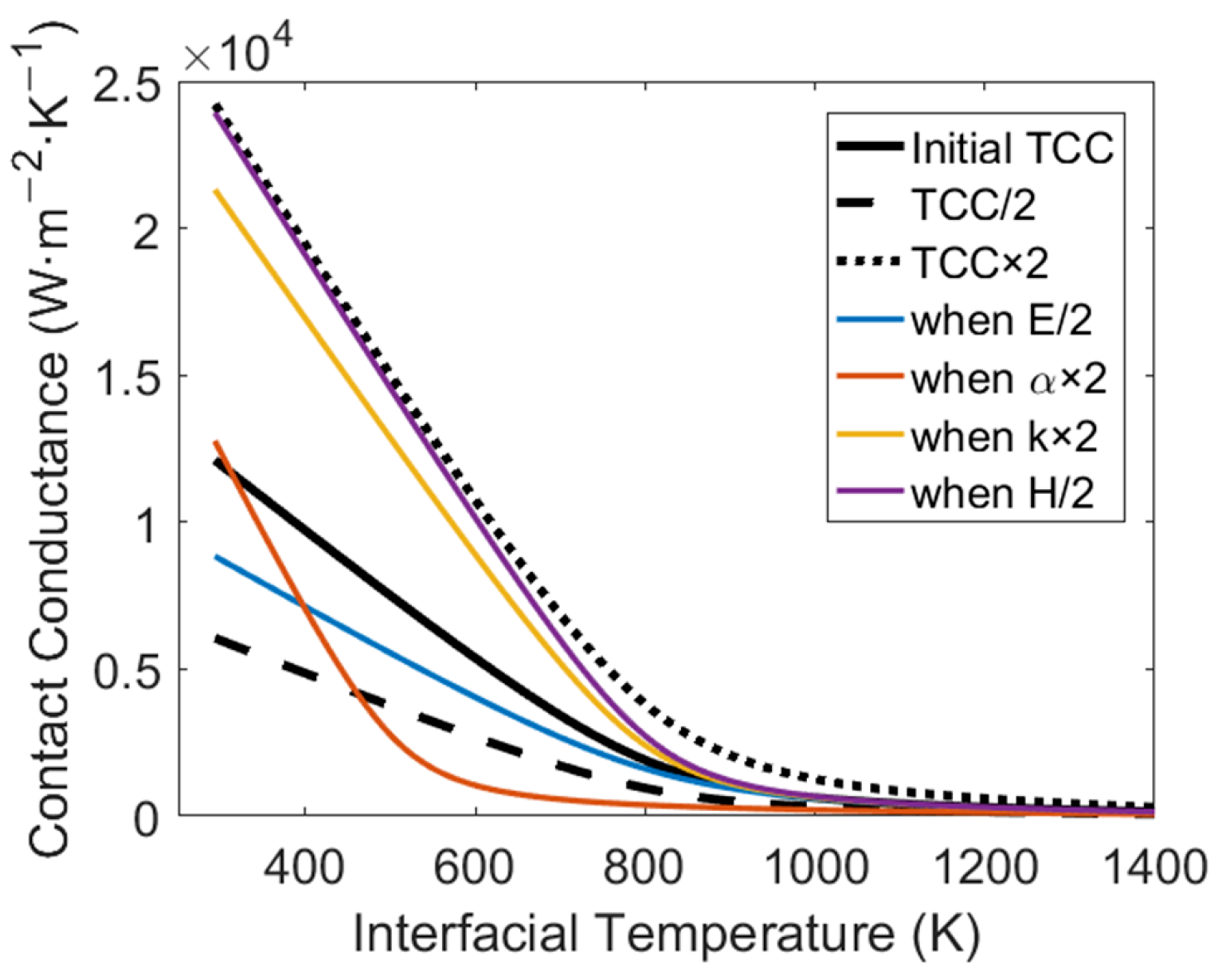
3.3. Quasi-Quantitative Discussion on Other Influencing Factors of TCC

In the previous sections, we demonstrated that the qualitative response modes of h s depend only on the size relationship of the thermal expansion coefficients and the direction of heat flux among all relevant parameters. Nevertheless, other material properties and geometric parameters can still quantitatively influence TCC. Our theoretical approach allows for a quasi-quantitative analysis of their influencing patterns.
Examining Equations (12)–(16), we observe that some parameters appear only in E , so their influences on TCC relate to how E affects TCC and how they influence E . A larger E decreases the pressure-induce gap h s / E in Equation (14) or Equation (16), and to compensate for this, the quantitative change in h s responding to any change in q and T 1 will need to be larger, indicating a stronger response. Such is the influencing pattern of, for example, higher elastic modulus of either cylinder, lower effective surface roughness or hardness, as they all contribute to a larger E . Higher thermal conductivity not only leads to a larger E but also a smaller q · C q . As a result, the response of h s to T 1 will be stronger, but stay nearly the same for q. The influencing patterns of geometric parameters are more subtle as they intertwine in many terms in the governing equations. One observation is that a thinner composite cylinder with constant r b (i.e., r c , r b , and r a closer together) makes E smaller, thus weakening the response of h s .
Another useful insight from the quasi-quantitative analysis concerns the coupled effects of changing heat flux q and temperature T 1 simultaneously, which is more realistic than changing only one factor. For example, consider the startup process of a heat-pipe reactor where both q and T 1 increase. In some scenarios, such as the Mo-SS system under outward heat flow, the effects of increasing q and T 1 on h s are opposite, and the net effect is determined by the quantitatively larger influence, as illustrated in Figure 13. It is clear from Equation (14) or Equation (16) that the quantitative influence of T 1 depends on the value of C T , while that of q depends on C q and r b α o / ( h s + h r ) . By examining the detailed expression of C q and C T in Equation (15), we conclude that the impact of T 1 is strong when the difference between the thermal expansion coefficients is large, and the impact of q is strong when the thermal expansion coefficient of each cylinder is large, the thermal conductivity is low or the current interfacial conductance h s is low.

4. Conclusions

This study systematically investigated the general response modes of cylindrical thermal contact conductance (TCC) to changes in temperature and heat flux. By adopting a theoretical and numerical approach, we can circumvent the limitations of experimental studies and provide insights into the behavior of TCC for arbitrary material combinations and heat flux directions. Our findings indicate that:
  • For outward heat flux, TCC consistently increases with heat flux and has three possible response modes to temperature changes, depending on the thermal expansion coefficients of the materials involved.
  • For inward heat flux, there are six possible response modes due to the coexistence of two opposite solutions of TCC, corresponding to good and bad interfacial contact states, for the same interfacial conditions. This behavior arises from the asymmetry between the thermal expansions of the inner and outer cylinders. Results also indicate that fast heating may lead to poor contact state, and thus should be avoided.
  • The qualitative response patterns are governed by the relative thermal expansion coefficients and heat flux direction, while other material properties and geometric parameters influence the quantitative response of TCC.
The insights gained from this study can be applied to optimize the design and performance of systems involving cylindrical joints, such as heat-pipe reactors, by better understanding the factors affecting TCC under various working conditions. Future work may focus on extending the analysis to a more quantitative level by further experimental validation.

Author Contributions

Conceptualization, all authors; methodology, F.L.; software, F.L.; validation, F.L.; formal analysis, F.L.; writing—original draft preparation, F.L.; writing—review and editing, F.L., M.M. and Y.Z.; supervision, W.L. and Q.X.; project administration, W.L. and Q.X.; funding acquisition, F.L., W.L. and Q.X. All authors have read and agreed to the published version of the manuscript.

Funding

This research was funded by NSF grant of China (No. 12302341).

Data Availability Statement

The original contributions presented in this study are included in the article. Further inquiries can be directed to the corresponding author.

Conflicts of Interest

The authors declare no conflicts of interest.

Abbreviations

The following abbreviations are used in this manuscript:
SSStainless Steel
TCCThermal Contact Conductance

References

  1. Górecki, G.; Łęcki, M.; Gutkowski, A.N.; Andrzejewski, D.; Warwas, B.; Kowalczyk, M.; Romaniak, A. Experimental and numerical study of heat pipe heat exchanger with individually finned heat pipes. Energies 2021, 14, 5317. [Google Scholar] [CrossRef]
  2. Maghrabie, H.M.; Olabi, A.; Alami, A.H.; Al Radi, M.; Zwayyed, F.; Wilberforce, T.; Abdelkareem, M.A. Numerical simulation of heat pipes in different applications. Int. J. Thermofluids 2022, 16, 100199. [Google Scholar] [CrossRef]
  3. Singh, S.; Sørensen, K.; Condra, T.J. Influence of the degree of thermal contact in fin and tube heat exchanger: A numerical analysis. Appl. Therm. Eng. 2016, 107, 612–624. [Google Scholar] [CrossRef]
  4. Tang, S.; Wang, C.; Zhang, D.; Tian, W.; Su, G.; Qiu, S. Thermoelectric performance study on a heat pipe thermoelectric generator for micro nuclear reactor application. Int. J. Energy Res. 2021, 45, 12301–12316. [Google Scholar] [CrossRef]
  5. Tang, D.; Li, D.; Peng, Y.; Du, Z. A new approach in evaluation of thermal contact conductance of tube–fin heat exchanger. Appl. Therm. Eng. 2010, 30, 1991–1996. [Google Scholar] [CrossRef]
  6. Deng, J.; Wang, T.; Liu, X.; Zhang, T.; He, H.; Chai, X. Experimental study on transient heat transfer performance of high temperature heat pipe under temperature feedback heating mode for micro nuclear reactor applications. Appl. Therm. Eng. 2023, 230, 120826. [Google Scholar] [CrossRef]
  7. Gibson, M.; Schmitz, P. Higher power design concepts for NASA’s kilopower reactor. In Proceedings of the 2020 IEEE Aerospace Conference, Big Sky, MT, USA, 7–14 March 2020; IEEE: New York, NY, USA, 2020; pp. 1–9. [Google Scholar]
  8. Merrigan, M.; Keddy, E.; Sena, J. Transient Heat Pipe Investigations for Space Power Systems; Report; Los Alamos National Laboratory (LANL): Los Alamos, NM, USA, 1985.
  9. Madhusudana, C.; Fletcher, L.; Peterson, G. Thermal conductance of cylindrical joints—A critical review. J. Thermophys. Heat Transf. 1990, 4, 204–211. [Google Scholar] [CrossRef]
  10. Kumar, S.; Tariq, A. Effects of contact-nature on transient thermal contact conductance. Int. J. Therm. Sci. 2019, 137, 299–312. [Google Scholar] [CrossRef]
  11. Rosochowska, M.; Balendra, R.; Chodnikiewicz, K. Measurements of thermal contact conductance. J. Mater. Process. Technol. 2003, 135, 204–210. [Google Scholar] [CrossRef]
  12. Singhal, V.; Litke, P.J.; Black, A.F.; Garimella, S.V. An experimentally validated thermo-mechanical model for the prediction of thermal contact conductance. Int. J. Heat Mass Transf. 2005, 48, 5446–5459. [Google Scholar] [CrossRef]
  13. Tariq, A.; Asif, M. Experimental investigation of thermal contact conductance for nominally flat metallic contact. Heat Mass Transf. 2016, 52, 291–307. [Google Scholar] [CrossRef]
  14. Sun, X.; Meng, C.; Duan, T. Fractal model of thermal contact conductance of two spherical joint surfaces considering friction coefficient. Ind. Lubr. Tribol. 2022, 74, 93–101. [Google Scholar] [CrossRef]
  15. Kumar, A.; Rana, S.; Gori, Y.; Sharma, N.K. Thermal contact conductance prediction using FEM-based computational techniques. In Advanced Computational Methods in Mechanical and Materials Engineering; CRC Press: Boca Raton, FL, USA, 2021; pp. 183–217. [Google Scholar]
  16. Yang, Z.; Yi, S.; Li, J.; Ding, S. Thermal and force simulation modelling of graphene oxide nanosheets as cutting fluid additives during Ti-6Al-4V drilling process. Int. J. Therm. Sci. 2025, 210, 109608. [Google Scholar] [CrossRef]
  17. Brazhenko, V.; Qiu, Y.; Cai, J.; Wang, D. Thermal Evaluation of Multilayer Wall with a Hat-Stringer in Aircraft Design. Stroj. Vestn.-J. Mech. Eng. 2022, 68, 635–641. [Google Scholar] [CrossRef]
  18. Sunil Kumar, S.; Abilash, P.; Ramamurthi, K. Thermal contact conductance for cylindrical and spherical contacts. Heat Mass Transf. 2004, 40, 679–688. [Google Scholar] [CrossRef]
  19. Tio, K.K.; Chuan, T.K. Thermal resistance of two solids in contact through a cylindrical joint. Int. J. Heat Mass Transf. 1998, 41, 2013–2024. [Google Scholar] [CrossRef]
  20. Liu, J.; Ma, C.; Wang, S. Thermal contact conductance between rollers and bearing rings. Int. J. Therm. Sci. 2020, 147, 106140. [Google Scholar] [CrossRef]
  21. Tafazzoli Aghvami, K.; Shojaeefard, M.H.; Jourabian, M. Steady-state estimation of thermal contact conductance between sliding disk and stationary cylinder with similar/dissimilar materials under the isothermally heated boundary condition. Heat Transf. 2021, 50, 8012–8034. [Google Scholar] [CrossRef]
  22. Ayers, G.; Fletcher, L.; Madhusudana, C. Thermal contact conductance of composite cylinders. J. Thermophys. Heat Transf. 1997, 11, 72–81. [Google Scholar] [CrossRef]
  23. Madhusudana, C.V. Thermal conductance of cylindrical joints. Int. J. Heat Mass Transf. 1999, 42, 1273–1287. [Google Scholar] [CrossRef]
  24. Madhusudana, C.V.; Madhusudana, C. Thermal Contact Conductance; Springer: New York, NY, USA, 1996; Volume 79. [Google Scholar]
  25. Mikić, B. Thermal contact conductance; theoretical considerations. Int. J. Heat Mass Transf. 1974, 17, 205–214. [Google Scholar] [CrossRef]
  26. Tien, C. A correlation for thermal contact conductance of nominally flat surfaces in vacuum. In Proceedings of the Thermal Conductivity, Proceedings of the Seventh Conference, National Bureau of Standards Special Publication, Gaithersburg, MD, USA, 13–16 November 1967; Volume 302, pp. 755–759. [Google Scholar]
  27. Yüncü, H.; Kakaç, S. Thermal contact conductance-theory and applications. In Cooling of Electronic Systems; Springer: Dordrecht, The Netherlands, 1994; pp. 677–702. [Google Scholar]
  28. Hetnarski, R.B.; Eslami, M.R.; Gladwell, G. Thermal Stresses: Advanced Theory and Applications; Springer: Berlin/Heidelberg, Germany, 2009; Volume 41. [Google Scholar]
  29. Lurie, A.I. Theory of Elasticity; Springer Science & Business Media: Berlin/Heidelberg, Germany, 2010. [Google Scholar]
  30. Ugural, A.C.; Fenster, S.K. Advanced Strength and Applied Elasticity; Pearson Education: Hoboken, NJ, USA, 2003. [Google Scholar]
Figure 1. The physical model in this study: the cross-section of two concentric hollow cylinders with radii at the innermost surface, at the outer surface of the inner cylinder, and the outermost surface being r a , r b , and r c , respectively. We investigate how the contact conductance of the cylindrical interface responds to changes in heat flux q and temperature T 1 , for arbitrary material combinations and heat flux directions.
Energies 18 02454 g001
Figure 2. Mesh independence study of ABAQUS. A mesh size of 0.5 mm is adopted for all following ABAQUS simulations.
Energies 18 02454 g002
Figure 3. The cylindrical TCC h s for a stainless steel/molybdenum composite cylinder under outward heat flux at (a) q = 2 × 10 5 W/m2, varying temperatures T 1 , and (b) T 1 = 300 K, varying heat fluxes q, computed from our method and ABAQUS simulation. Results show good agreement.
Energies 18 02454 g003
Figure 4. Comparison of our method against one experiment by Hsu and Tam [10].
Energies 18 02454 g004
Figure 5. Numerically computed contours of thermal contact conductance h s against interfacial temperature T 1 and heat flux q for (a) SS-Mo, (b) Mo-SS and (c) Mo-Mo composite cylinders, under outward heat flux. These three contours computed from specific sets of parameters can be proven to represent three general response modes for arbitrary material combinations under outward heat flux.
Energies 18 02454 g005
Figure 6. Numerically computed contours of interfacial temperature jump Δ T against interfacial temperature T 1 and heat flux q for (a) SS-Mo, (b) Mo-SS and (c) Mo-Mo composite cylinders, under outward heat flux.
Energies 18 02454 g006
Figure 7. The three general response modes of h s to changes in q and T 1 depending on the three possibilities of relative thermal expansion coefficients, under outward heat flux. Conceptually, the response of h s to q and T 1 should always cancel out their effects on the interfacial gap/interference to rebalance Equation (14) and maintain the cylinders in contact.
Energies 18 02454 g007
Figure 8. Sensitivity analyses at q = 1 × 10 5 W/m2 regarding individual thermo-physical parameters.
Energies 18 02454 g008
Figure 9. Numerically computed contours of thermal contact conductance h s against interfacial temperature T 1 and heat flux q for (a,d) SS-Mo, (b,e) Mo-SS and (c,f) Mo-Mo composite cylinders, under inward heat flux. The blank parts on the contours indicate that the cylinders have lost contact. Two solutions of h s can coexist for the same material combinations, and (ac) shows the contours of the larger solution. These six contours computed from specific sets of parameters can be proven to represent six general response modes for arbitrary material combinations under inward heat flux.
Energies 18 02454 g009
Figure 10. Numerically computed contours of interfacial temperature jump Δ T against interfacial temperature T 1 and heat flux q for (a,d) SS-Mo, (b,e) Mo-SS and (c,f) Mo-Mo composite cylinders, under inward heat flux. The blank parts on the contours indicate that the cylinders have lost contact. Two solutions can coexist for the same material combinations, and (ac) shows the contours for the larger solution of h s .
Energies 18 02454 g010
Figure 11. Conceptual illustration for the number of solutions under inward heat flux. The non-monotonic trend of f ( h s ) allows for at most two coexistent solutions of h s .
Energies 18 02454 g011
Figure 12. The six general response modes of h s to changes in q and T 1 depending on the three possibilities of relative thermal expansion coefficients and two coexistent solutions, under inward heat flux. Conceptually, the response of h s to q and T 1 should always cancel out their effects on the interfacial gap/interference to rebalance Equation (16) and maintain the cylinders in contact.
Energies 18 02454 g012
Figure 13. The contour of h s for Mo-SS system under outward heat flow, as in Figure 3b. The red and blue arrows both represent the simultaneous increase of q and T 1 , but the resulting response of h s is opposite.
Energies 18 02454 g013
Table 1. Material and geometrical parameter in Hsu and Tam’s work [10].
Inner CylinderOuter Cylinder
MaterialAlclad 2011-T351Stainless steel AISI 304
Elastic modulus (Pa)7.1 × 10102 × 1011
Thermal expansion coefficient (K−1)2.28 × 10−51.73 × 10−5
Thermal conductivity (W·m−1·K−1)15516.5
Poisson’s ratio0.280.33
Hardness (Pa)9.33 × 1082.42 × 109
Surface roughness (m)3 × 10−61.27 × 10−6
Inner radius (m)1.1 × 10−22.958 × 10−2
Outer radius (m)2.958 × 10−23.626 × 10−2
Table 2. Material properties of stainless steel and molybdenum used in this work.
Material PropertiesStainless SteelMolybdenum
Elastic modulus (Pa)2 × 10113.3 × 1011
Thermal expansion coefficient (K−1)1.6 × 10−55.35 × 10−6
Thermal conductivity (W·m−1·K−1)16.5138
Poisson’s ratio0.280.38
Hardness (Pa)2.75 × 1091.4 × 109
Emissivity0.40.4
Disclaimer/Publisher’s Note: The statements, opinions and data contained in all publications are solely those of the individual author(s) and contributor(s) and not of MDPI and/or the editor(s). MDPI and/or the editor(s) disclaim responsibility for any injury to people or property resulting from any ideas, methods, instructions or products referred to in the content.

