1. Introduction
A distribution transformer is a critical power conversion device at the terminal of a distribution network. Its condition evaluation provides maintenance personnel with the basis for equipment inspection decisions, and it plays a crucial role in both equipment maintenance and the safe operation of the power system [
1,
2]. In practical engineering, the operation condition of the distribution transformer is influenced by internal operation factors, external environmental conditions, and load operation [
3,
4]. Condition evaluation of distribution transformers has become a difficult and hot topic in research in the power industry [
5,
6,
7,
8].
Currently, condition evaluation methods for distribution transformers primarily focus on the uncertainty reasoning method and machine learning method. Machine learning methods mainly include artificial neural networks (ANNs) [
9], support vector machines (SVMs) [
10], deep belief networks (DBNs) [
11], etc. Based on the machine learning method, the condition evaluation for distribution transformers demands substantial training datasets. However, in practical engineering, the operational data, which are difficult to obtain, limit the application of this method in the field of condition evaluation [
12].
Uncertainty reasoning methods mainly include analytic hierarchy process (AHP), fuzzy theory, and the cloud model. Regarding the condition evaluation of distribution transformers, many scholars have achieved a series of research findings. Shah et al. [
13] developed a distribution transformer condition evaluation model by analyzing transformer line data, load data, transformer location, and input impedance. Zhang et al. [
14] established a transformer lifetime evaluation model based on AHP and variable weight theory. Manoj et al. [
15] proposed a hybrid AHP-based transformer condition evaluation model by examining dissolved gases as well as insulating oil and paper. Soni et al. [
16] proposed a multi-indicator-based transformer condition evaluation model by establishing an indicator criterion from electrical, thermal, and chemical data. Hamoud et al. [
17] proposed a transformer condition evaluation model by analyzing load transfer strategies among substations. Yi et al. [
18] proposed a transformer condition evaluation model by using the gray-cloud evidence method.
In summary, many research results have been achieved in power transformer condition evaluation, but there is still space for further exploration in the following aspects:
The existing studies on evaluating the transformer’s condition mostly focused on medium- and high-voltage transformers, and the indicator systems have been established based on the internal operation condition, such as the dissolved gas content, the health of the insulating oil, and the insulation paper. However, the effect of changes in the external environmental condition and the load operation condition following capacity expansion connection have mostly been overlooked in transformer condition evaluation. The condition evaluation of a distribution transformer is even less mentioned.
The existing methods for determining the weight in power transformer condition evaluation predominantly rely on the AHP for the subjective weight and the entropy weight method for the objective weight. This approach results in cumbersome implementation procedures and the ineffective extraction of critical information from evaluation data.
The existing condition evaluation methods of transformers fail to simultaneously address the fuzziness of the operation condition and the randomness of the underlying indicators. Moreover, these methods cannot effectively analyze whether the internal operation condition, external environmental condition, and load operation condition are healthy when evaluating the overall operation condition of distribution transformers.
To address these challenges, the contributions of this work are summarized as follows:
A comprehensive evaluation indicator system of the distribution transformer’s operation condition is established, which comprehensively considers the impacts of the internal operation condition, external environmental condition, and load operation condition. Moreover, the analysis of the load operation condition specifically analyzes the effect of post-business-expansion load changes on the transformer’s condition.
The comprehensive weights of the condition evaluation indicators for distribution transformers are derived by the ORA-PCA method and the principle of minimum discrimination information. This approach eliminates the need for judgment matrix construction and consistency verification, effectively extracting critical information from the data. Additionally, it enhances the accuracy of the comprehensive weight.
A comprehensive condition evaluation model for distribution transformers is developed with a comprehensive evaluation indicator system for the operational condition of the distribution transformer. This model not only evaluates the overall operation condition of distribution transformers but also assesses the internal operation condition, external environmental condition, and load operation condition. Sensitivity analysis is conducted for the transformer’s overall operation condition, internal operation condition, external environmental condition, and load operation condition, providing robust theoretical support for classification condition boundaries.
This study firstly establishes a comprehensive evaluation indicator system for a distribution transformer’s operation condition. The comprehensive weight for each indicator of the distribution transformer is calculated by using the ORA-PCA method and the principle of minimum discrimination information. Based on this, an improved golden section method is utilized to construct evaluation criterion clouds. A comprehensive condition evaluation model for distribution transformers is developed based on the cloud model and the expectation curve method by considering the internal operation condition, external environmental condition, and load operation condition. Finally, the model effectiveness is validated by the case study, and a sensitivity analysis is conducted for the internal operation condition, external environmental condition, and load operation condition.
The organizational structure of this paper is as follows:
Section 2 establishes the comprehensive evaluation indicator system for the distribution transformer’s operation condition. In
Section 3, the comprehensive weighting model for evaluation indicators is developed for the distribution transformer, and a comprehensive condition evaluation model is built based on the cloud model and the expectation curve method. In
Section 4, the comprehensive condition evaluation process of the distribution transformer is elaborated in detail. In
Section 5, the model effectiveness is validated by the case study, and a sensitivity analysis is also conducted. Finally, the conclusions are presented in
Section 6.
2. Comprehensive Evaluation Indicator System for Distribution Transformer Operation Condition
2.1. Selection of Evaluation Indicators
A distribution transformer is a complex system, and there exists many condition indicators that can reflect its operation condition. In order to accurately evaluate the operation condition of a distribution transformer, it is necessary to adopt a comprehensive distribution transformer indicator system so as to establish an effective condition evaluation model of the distribution transformer.
References [
19,
20,
21,
22], the IEC 60076-1:2011 [
23] standard, and the IEC 60076-3:2018 [
24] standard indicate that the short-circuit impedance, dielectric loss, top-oil temperature, and insulation resistance are the main factors that affect the service life, reliability, stability, and insulation performance of distribution transformers. Therefore, this study selects the short-circuit impedance, dielectric loss, top-oil temperature, and insulation resistance as the internal operation condition indicators for distribution transformers. Reference [
25] indicates that the relative humidity, atmospheric pressure, environmental temperature, and precipitation are the main environment factors that affect the distribution transformer’s operation condition. Therefore, this study selects the relative humidity, atmospheric pressure, environmental temperature, and precipitation as the external environment condition indicators for distribution transformer. References [
26,
27,
28,
29] indicate that the load expansion growth rate, proportion of new load to total load, load utilization rate post load expansion, and voltage deviation induced by load expansion are the main load factors that affect the distribution transformer operation condition. Therefore, this study selects the load expansion growth rate, proportion of new load to total load, load utilization rate post load expansion, and voltage deviation induced by load expansion as the load operation condition indicators for distribution transformers.
Based on the above analysis, in order to establish the comprehensive evaluation indicator system for distribution transformers, the internal operation condition indicators (the short-circuit impedance, dielectric loss, top-oil temperature, and insulation resistance), external environmental condition indicators (relative humidity, atmospheric pressure, environmental temperature, and precipitation), and load operation condition indicators (the load expansion growth rate, proportion of new load to total load, load utilization rate post load expansion, and voltage deviation induced by load expansion) are selected, as illustrated in
Figure 1.
Figure 1 illustrates the evaluation indicator system for the operation condition of a distribution transformer, which is primarily composed of three layers: the objective layer, the criterion layer, and the indicator layer. The objective layer represents the comprehensive evaluation of the distribution transformer’s condition. The criterion layer is mainly composed of the internal operation condition, external environmental condition, and load operation condition. The indicator layer is mainly composed of changes in the short-circuit impedance (A1), dielectric loss (A2), top-oil temperature (A3), insulation resistance (A4), relative humidity (A5), atmosphere pressure (A6), environmental temperature (A7), precipitation (A8), load expansion growth rate (A9), the proportion of new load to total load (A10), load utilization rate post load expansion (All), and voltage deviation induced by load expansion (A12).
2.2. Processing of Evaluation Indicators
In the process of conducting a condition evaluation, the min–max normalization method is applied to standardize both the indicator values and their condition thresholds, due to the inconsistency in the magnitudes and dimensions of the indicator data and the requirement that the cloud model synthesis for indicator state levels be performed within a unified domain [
30].
For indicators where larger-is-better, the normalization procedure is defined as shown in Equation (1)
For indicators where smaller-is-better, the normalization procedure is defined as shown in Equation (2).
In Equations (1) and (2), xi denotes the original value of the evaluation indicator; represents the normalized value of xi; and and correspond to the maximum and minimum threshold values of the indicator, respectively.
3. Condition Evaluation Model of Distribution Transformer
3.1. Establish the Subjective Weights Model Based on the ORA Method
The ORA method is a subjective weight technique, which is suitable for evaluating indicator systems with fuzziness and randomness [
31]. Compared to other subjective weighting methods, it offers computational simplicity by eliminating the need for judgment matrix construction and consistency verification. The implementation steps are as follows:
Establish ordinal relationships between indicators. The indicators are ranked based on their relative importance to the distribution transformer operation condition. The relevant experts are invited to score each indicator on an integer scale of 1–10, where higher scores denote greater criticality to transformer performance. Then, the indicators are sorted in descending order of their scores.
Determine the relative importance of the indicators. According to
Table 1, the relative importance of adjacent evaluation indicators is quantified, and the ratio of the relative importance of indicator
Xk to that of indicator
Xk−1 is denoted by
Rk, as shown in Equation (3).
In Equation (3), Wk−1 represents the weight of the k-th indicator computed by the ORA method.
The value of
Rk is determined based on expert opinions, and the order relation method is applied to calculate the indicator weights, as shown in Equation (4).
In Equation (4), wn represents the weight of the n-th indicator; wn−1 represents the weight of the (n − 1)-th indicator; and W′ denotes the subjective weight vector of the evaluation indicators for the operation condition of the distribution transformer.
3.2. Establish the Objective Weights Model Based on the PCA Method
The PCA method converts high-dimensional data into low-dimensional data by using linear transformation [
32]. It can effectively evaluate the importance of each indicator influencing the operation condition of distribution transformers by analyzing the magnitude of the principal component loading. The specific steps are as follows:
Construct the sample matrix D for the distribution transformer evaluation indicator and perform normalization and standardization processing on the sample data.
Establish the principal component expression. The covariance matrix of the standardized sample matrix, the eigenvalues of the covariance matrix, and the corresponding eigenvectors are computed. Additionally, the eigenvalues are arranged in descending order, as shown in Equation (5).
In Equation (5), Pq (q = 1, 2, …, Q) represents the q-th principal component; Xj denotes the standardized value of the evaluation indicator; and aqj is the principal component loading coefficient, which corresponds to the j-th component of the eigenvector associated with the q-th eigenvalue.
- 3.
Select the principal components and compute the variance contribution rate cq of the q-th principal component. The variance contribution rate Pq represents the proportion of the variance that is explained by the principal component Pq relative to the total variance of the operation condition evaluation indicators of the distribution transformer, as shown in Equation (6).
- 4.
Calculate the objective weights for the operation condition evaluation indicators of the distribution transformer. By weighting the indicators, the objective weight of each evaluation indicator is determined, as shown in Equations (7) and (8).
In Equations (7) and (8), represents the objective weight of the j-th evaluation indicator; denotes the information content of the j-th evaluation indicator across all Q principal components; represents the information content of the j-th evaluation indicator within the selected U principal components; and W′′ is the objective weight vector for the operation condition evaluation indicator of the distribution transformer.
3.3. Establish the Comprehensive Weight Model Based on the Principle of Minimum Discrimination Information
In Equations (9) and (10),
wj represents the comprehensive weight of the
j-th operation condition evaluation indicator of the distribution transformer [
33].
3.4. Establish the Comprehensive Condition Evaluation Model for the Distribution Transformer Based on the Cloud Model
3.4.1. Cloud Model
Based on probability theory and fuzzy mathematics, the cloud model can effectively account for the fuzziness of the distribution transformer condition and the randomness of the underlying operation condition evaluation indicators [
34]. The cloud model characterizes a qualitative concept T(
Ex,
En,
He) by using three numerical features: expectation (
Ex), entropy (
En), and hyper-entropy (
He) [
35,
36]. In our study, Ex represents the average value of the corresponding operation condition indicator of the distribution transformer; En represents the acceptable numerical range of the concept, reflecting both the fuzziness and randomness of the distribution transformer operation condition; and He quantifies the uncertainty of the Entropy (
En) and primarily affects the thickness of the generated cloud.
3.4.2. Establish the Evaluation Standard Cloud Model
To enhance the intuitiveness of the evaluation results, relevant documents, regulations, and expert consultations are considered, and the evaluation standard cloud serves as a reference baseline for evaluating the operation condition of the distribution transformer in our study. Within the domain [0, 100], the score range is divided into five levels from highest to lowest: failure, warning, degraded, normal, and healthy. The standard cloud is determined by the improved golden section method [
37], and its numerical characteristics are presented in
Table 2. The standard cloud is illustrated in
Figure 2.
3.4.3. Calculation Method for Numerical Characteristics of Cloud Model at Each Level
In Equation (11), Xi represents the sample value; n denotes the number of samples; and is the sample mean.
- 2.
The numerical characteristics of the cloud model at the criterion layer and the comprehensive cloud characteristics at the objective layer are obtained by weighting the numerical characteristics of the indicator layer. The corresponding weighted calculation formula is shown in Equation (12).
In Equation (12), represents the expectation of the j-th indicator; represents the entropy of the j-th indicator; represents the hyper-entropy of the j-th indicator; and wj represents the comprehensive weight of the j-th indicator.
3.5. Establish the Proximity Degree Calculation Model Based on the Expectation Curve Method
The expectation curve method is used to determine the similarity between the two cloud models by calculating the intersection of the enclosed areas by their expectation curves and the
x-axis [
38]. This method provides a clear and convenient way to reflect the relationship between the variables and evaluation results. The intersection of the enclosed areas is calculated by the expectation curves of the two cloud models and the
x-axis, as shown in Equation (13).
In Equation (13),
;
;
represents the probability density function of the standard normal distribution;
En1 and
En2 are the expectations of the expectation curves of the
M1 and
M2 cloud models, respectively; and
S is the intersection of the enclosed areas by the expectation curves of the two cloud models and the
x-axis, as shown in Equation (14).
4. Comprehensive Condition Evaluation Process of the Distribution Transformer Based on the Cloud Model and Expectation Curve Method
Based on
Section 3.4 and
Section 3.5, the comprehensive condition evaluation of the distribution transformer is conducted by the cloud model and the expectation curve method. The specific steps are as follows, with the process flowchart shown in
Figure 3.
Step 1: Based on
Section 2.1 and
Section 2.2, a comprehensive evaluation indicator system for the distribution transformer operation condition is established from the internal operation condition, external environmental condition, and load operation condition. The data of each indicator can be normalized by using Equations (1) and (2).
Step 2: The subjective weights are determined by the ORA method. The order relationships of the distribution transformer condition indicators can be defined, and the relative importance can be determined based on
Table 1. Consequently, the subjective weight of the distribution transformer condition indicators can be derived.
Step 3: The objective weights are determined by the PCA method. The sample matrix of the condition indicators is constructed, and the variance contribution rate of each principal component is computed. Consequently, the objective weight of the distribution transformer condition indicators can be derived.
Step 4: The comprehensive weights are determined by the principle of minimum discrimination information. The objective function is set, and the comprehensive weights of the distribution transformer operation condition indicators are solved under the given constraints.
Step 5: The evaluation cloud numerical characteristics of the indicator layer, the criterion layer, and the target layer are calculated based on the cloud model. The cloud numerical characteristics for each evaluation indicator of the distribution transformer operation condition are obtained by using Equation (11). The evaluation clouds of the internal operation condition, the external environmental condition, the load operation condition, and the overall operation condition of the distribution transformer can be obtained by using the comprehensive weights derived from Step 4 and Equation (12).
Step 6: Based on the expectation curve method, the proximity degrees between the internal operation condition, external environmental condition, load operation condition, overall operation condition of the distribution transformer, and the five standard condition cloud models are respectively calculated, thereby determining the condition category of each evaluation object.
Step 7: Based on the expectation curve method and the cloud model, a sensitivity analysis is performed for the internal operation condition, external environment, load condition, and overall operation condition. The proximity degree is also calculated between different conditions and standard clouds to analyze the sensitivity of each condition.
5. Case Study Analysis
5.1. Case Study Overview
In this study, a distribution transformer (Model: S11-M-315/10), located in a high environmental temperature and substantial rainfall area, is selected as the research subject. The distribution transformer has a rated capacity of 80 kVA, a voltage level of 10 kV, and an insulation class of H. Based on the actual engineering site, via online monitoring and routine maintenance testing in a certain province, the original data are shown in
Table 3. Specifically, the internal operation data are acquired through the transformer monitoring system and power-system tests; the external environmental data are recorded by on-site meteorological instruments; and the load operation data are obtained from the SCADA system and metering automation platform.
Based on the transformer (S11-M-315/10) manual, network operation information, regional meteorological information, and relevant international transformer standards (IEC 60247 [
39], ASTM D924 [
40] etc.), the classification of indicators and standardized ranges are shown in
Table 4. Furthermore, the transformer condition data can be normalized by using Equations (1) and (2), and the standardized values are obtained as shown in
Table 5.
5.2. Comprehensive Weight Results
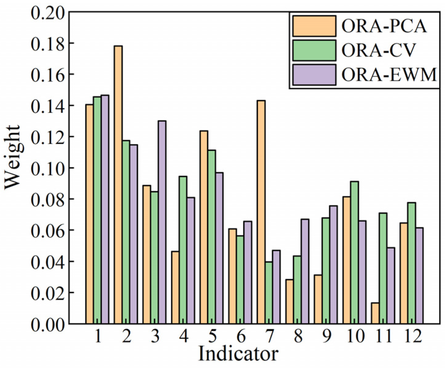
In this section, the comprehensive weights of the distribution transformer evaluation indicators are calculated based on the ORA-PCA method and the principle of minimum discrimination information. To validate the proposed weight calculation method, the ordering relation analysis–coefficient of variation method (ORA-CVM) and the ordering relation analysis–entropy weight method (ORA-EWM) are employed for comparison, and the results are shown in
Figure 4.
As indicated in
Figure 4, the comprehensive weights for the distribution transformer of the dielectric loss, insulation resistance, environmental temperature, load expansion growth rate, and load utilization rate post load expansion are 0.188, 0.042, 0.142, 0.035, and 0.015, respectively. These values show significant differences compared to the comprehensive weights obtained by the ORA-CVM and ORA-EWM methods, and the comprehensive weights for the remaining indicators exhibit minimal differences. The reason for this phenomenon is that the ORA-PCA method can effectively eliminate the correlations between the indicators.
Based on the above analysis, the indicators of changes in the short-circuit impedance, dielectric loss, and environmental temperature have the greatest impact on the overall operation condition of the distribution transformer. It is essential to strengthen the monitoring of key indicators, preventing deterioration of the distribution transformer’s operation condition.
5.3. Comprehensive Evaluation Results
Based on
Section 3.4 and
Section 3.5, the distribution transformer comprehensive evaluation results for the overall operation condition, internal operation condition, external environment, and load operation condition are analyzed and discussed in this section. Additionally, the light-yellow cloud map represents the cloud map of the condition to be evaluated, with the results shown in
Figure 5,
Figure 6,
Figure 7 and
Figure 8.
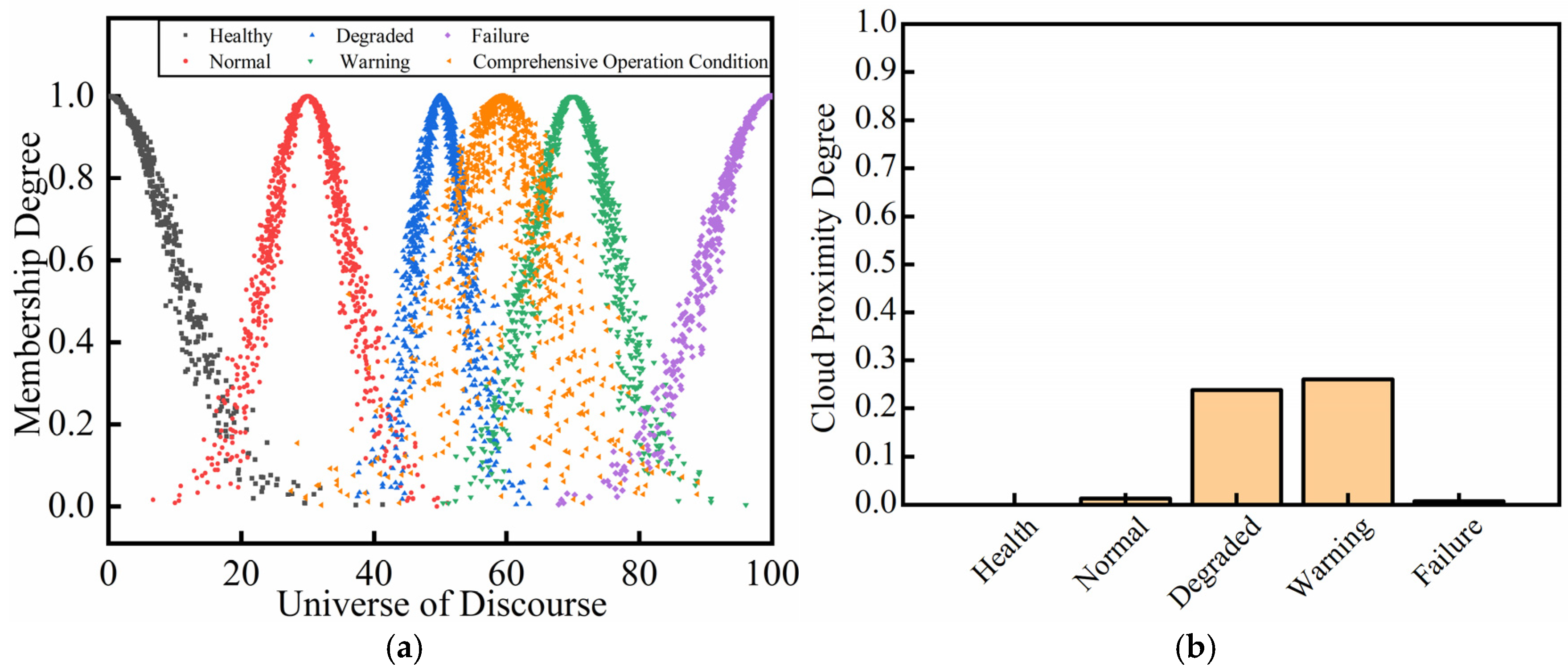
As indicated in
Figure 5a, the numerical characteristics of the distribution transformer overall operation condition cloud map are
Ex,
En, and
He, with values of 59.267, 2.007, and 0.929. The cloud map is close to the degraded condition cloud map, normal condition cloud map, and warning condition cloud map. Combining with
Figure 5b, the proximity degrees of healthy, normal, degraded, warning, and failure are 0, 0.020, 0.250, 0.260, and 0.010, respectively. The condition level ranking of the distribution transformer is as follows: warning > degraded > normal > healthy > failure. Based on the above analysis, the overall operation condition of the distribution transformer is determined to be in the warning condition.
According to
Figure 6a, the numerical characteristics of the distribution transformer internal operation condition cloud map are
Ex,
En, and
He, with values of 57.071, 5.683, and 2.426. The internal operation condition cloud map overlaps with the warning condition cloud map, degraded condition cloud map, normal condition cloud map, and healthy condition cloud map. Combining with
Figure 6b, the proximity degrees of healthy, normal, degraded, warning, and failure are 0, 0.005, 0.650, 0.037, and 0.001, respectively. The condition level ranking of the distribution transformer is as follows: degraded > warning > normal > failure > healthy. Based on the above analysis, the distribution transformer internal operation condition is determined to be in the degraded condition.
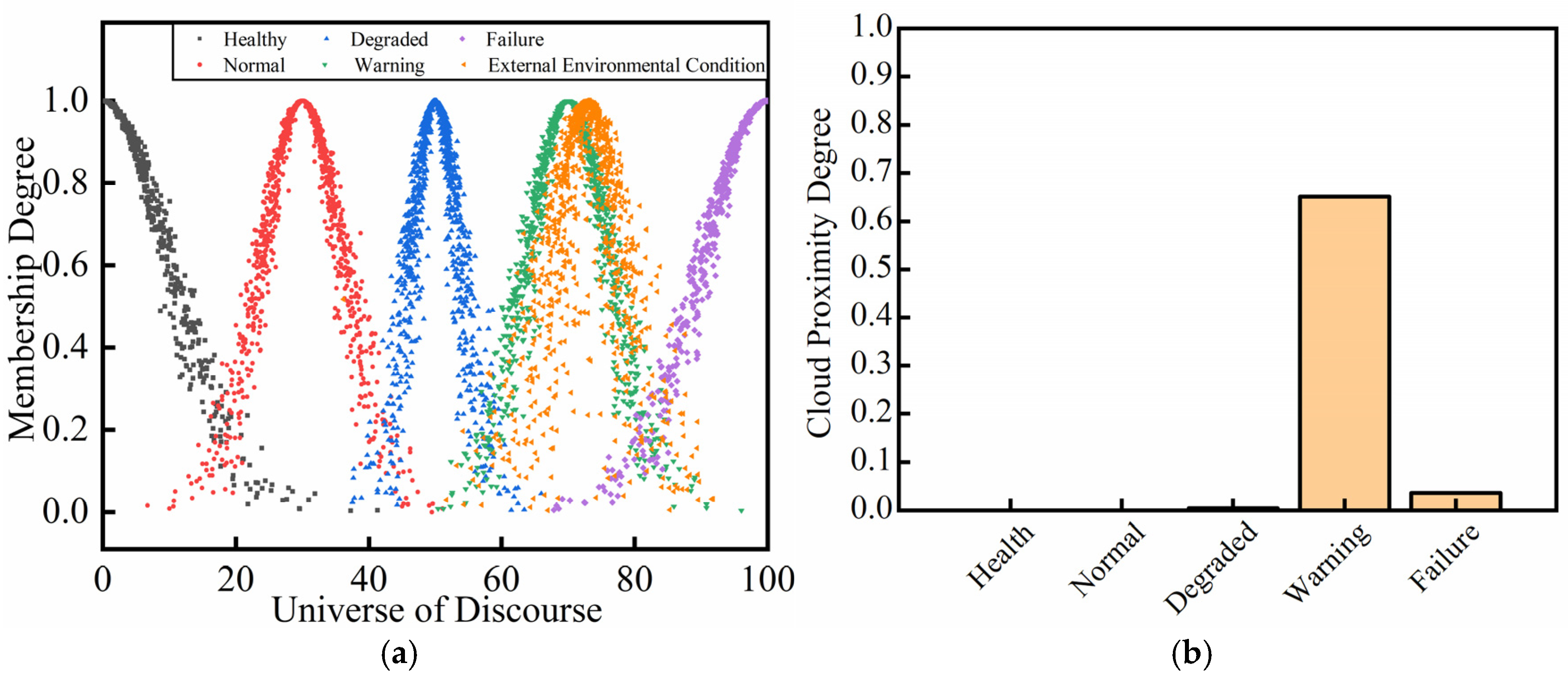
As indicated in
Figure 7a, the numerical characteristics of the distribution transformer external environmental condition cloud map are
Ex,
En, and
He, with values of 72.976, 4.938, and 2.357. The external environmental condition cloud map overlaps with the degraded condition cloud map, normal condition cloud map, and healthy condition cloud map. Combining with
Figure 7b, the proximity degrees of healthy, normal, degraded, warning, and failure are 0, 0, 0.005, 0.650, and 0.037, respectively. The condition level ranking of the distribution transformer is as follows: warning > failure > degraded > healthy (normal). Based on the above analysis, the distribution transformer external environmental condition is determined to be in the warning condition.
According to
Figure 8a, the numerical characteristics of the distribution transformer load operation condition cloud map are
Ex,
En, and
He, with values of 50.582, 7.033, and 2.986. The load operation condition cloud overlaps with the degraded, warning, normal, healthy and failure condition clouds. Combining with
Figure 8b, the proximity degrees of healthy, normal, degraded, warning, and failure are 0.001, 0.080, 0.560, 0.090, and 0.001, respectively. The condition level ranking of the distribution transformer is as follows: degraded > warning > normal > healthy (failure). The distribution transformer load operation condition is determined to be in the degraded condition.
Based on the above analysis, when the distribution transformer is in the warning condition, the internal operation condition and load operation condition are in the degraded condition, and the external environmental condition is in the warning condition. In practical applications, operation and maintenance personnel can develop graded response strategies by using cloud proximity. This approach enhances the accuracy and efficiency of distribution transformer condition evaluations and reduces the risk of sudden failures.
5.4. Sensitivity Analysis
Sensitivity refers to the change extent of the system output and the impact degree of system experiences when the model parameters change [
41]. Based on
Section 3.4 and
Section 3.5, sensitivity analysis of the distribution transformer overall operation condition, internal operation condition, external environmental condition, and load operation condition is conducted in this section.
As indicated in
Figure 9, it can be observed that the conditions of the distribution transformer transform from healthy to failure, with the increase in
Ex affecting the distribution transformer’s overall operation condition, internal operation condition, external environmental condition, and load operation condition.
Specifically, when Ex is in the range of [0, 18], the proximity degree between the distribution transformer condition cloud map and the healthy condition cloud map is greater than those with the other four condition cloud maps, and it indicates that the distribution transformer is in the healthy condition. At this stage, the transformer operates at a normal temperature, with a low dissolved gas content in the oil, good insulation performance, relatively stable load, and proper maintenance. Similarly, when Ex is in the range of [19, 41], the distribution transformer is in the normal condition. At this stage, if the Ex continues to rise, attention should be paid to regular maintenance, monitoring whether the top-oil temperature shows early signs of abnormality. When Ex is in the range of [42, 59], the distribution transformer is in the degraded condition. At this stage, with the slight deterioration in oil properties, a potentially high load rate can often be observed. It is necessary to take moderate preventive maintenance measures, such as enhancing inspections, shortening the maintenance period, and identifying potential hazards. When Ex is in the range of [60, 83], the distribution transformer is in the warning condition. At this stage, operators should carry out more in-depth inspection, testing, and diagnostics on the transformer. When Ex is in the range of [84, 100], the distribution transformer is in the failure condition. At this stage, the transformer windings already face severe insulation aging, overheating, and even a risk of breakdown.
As indicated in
Figure 9a–d, the differences in the impact of
Ex on the distribution transformer’s overall operation condition, internal operation condition, external environmental condition, and load operation condition are as follows:
Effect of Ex on the distribution transformer’s overall operation condition: when Ex is 0, the proximity degree between the distribution transformer’s overall operation condition and the healthy condition is 0.68. When Ex is respectively equal to 30, 50, 70, and 100, the corresponding analysis is similar. The overall operation condition is most likely to be in the normal condition and least likely to be in the warning condition.
Effect of Ex on the distribution transformer’s internal operation condition: when Ex is 0, the proximity degree between the distribution transformer’s internal operation condition and the healthy condition is 0.58. When Ex is respectively equal to 30, 50, 70, and 100, the corresponding analysis is similar. The internal operation condition is most likely to be in the normal condition and least likely to be in the failure condition and healthy condition.
Effect of Ex on the distribution transformer’s external environmental condition: when Ex is 0, the proximity degree between the distribution transformer’s external environmental condition and the healthy condition is 0.5. When Ex is respectively equal to 30, 50, 70, and 100, the corresponding analysis is similar. The external environmental condition is most likely to be in the degraded condition and least likely to be in the failure condition and healthy condition.
Effect of Ex on the distribution transformer’s load operation condition: when Ex is 0, the proximity degree between the distribution transformer’s load operation condition and the healthy condition is 0.70. When Ex is respectively equal to 30, 50, 70, and 100, the corresponding analysis is similar. The load operation condition is most likely to be in the warning condition and least likely to be in the degraded condition.
As mentioned above, it is crucial to focus on the distribution transformer’s internal operation condition and external environmental condition in practical engineering. Moreover, the impact of the load operation condition on the distribution transformer cannot be ignored. Additionally, the conversion patterns between different health levels of the transformer can be accurately identified.
6. Conclusions
This paper proposes a comprehensive condition evaluation of a distribution transformer by considering the internal operation, external environment, and load operation for business expansion. Firstly, the comprehensive evaluation indicator system for the distribution transformer’s operation condition is established. Secondly, the comprehensive weight for each indicator of the distribution transformer is calculated by using the ORA-PCA method and the principle of minimum discrimination information. Based on this, an improved golden section method is utilized to construct the evaluation criterion cloud. The comprehensive condition evaluation model for the distribution transformer is developed by using the cloud model and expectation curve method. Finally, case studies validate the model effectiveness, and sensitivity analysis is conducted for the transformer’s overall operation condition, internal operation condition, external environmental condition, and load operation condition. Furthermore, the research results demonstrate that the proposed method not only solves the question of the randomness of the factors affecting the operation condition and the complexity of calculating the weights of the operation condition indicators but also provides a theoretical basis for defining the boundaries of the overall operation condition, internal operation condition, external environmental condition, and load operation condition.
With the deepening application of large-model AI technology in power equipment manufacturing, operation, and maintenance, large-model AI technology will be integrated into uncertainty analysis methods, including AHP, fuzzy theory, and the cloud model, in our future work. These methods can provide better support for condition monitoring, reliability assessment, and fault diagnosis of the distribution transformer by their complementary strengths.
Author Contributions
Conceptualization, S.X. and D.D.; methodology, Y.H.; software, W.D.; validation, S.X.; formal analysis, D.D.; investigation, S.X.; resources, W.D.; data curation, D.D.; writing—original draft preparation, S.X.; writing—review and editing, Y.H.; visualization, Y.H.; supervision, D.D.; project administration, S.X.; funding acquisition, Y.H. All authors have read and agreed to the published version of the manuscript.
Funding
This research is funded by China Southern Power Grid Corporation Science and Technology project, grant number 031900KC23120073.
Data Availability Statement
Data are contained within the article.
Conflicts of Interest
Authors Shengxiang Xie, Danni Dai and Weifeng Dong were employed by the company Dongguan Power Supply Bureau of Guangdong Power Grid Co., Ltd. The remaining authors declare that the research was conducted in the absence of any commercial or financial relationships that could be construed as a potential conflict of interest.
Abbreviations
The following abbreviations are used in this manuscript:
| ORA-PCA | Ordering relation analysis–principal component analysis |
| ANN | Artificial neural network |
| SVM | Support vector machine |
| DBN | Deep belief network |
| ORA-CVM | Ordering relation analysis–coefficient of variation method |
| ORA-EWM | Ordering relation analysis–entropy weight method |
| AHP | Analytic hierarchy process |
References
- Brahami, Y.; Betie, A.; Meghnefi, F.; Fofana, I.; Yeo, Z. Development of a comprehensive model for drying optimization and moisture management in power transformer manufacturing. Energies 2025, 18, 789. [Google Scholar] [CrossRef]
- Ghorbi, E.; Nezhad, T.H. Seismic-isolation of a high-voltage power transformer with pseudo-rolling elastomeric isolators: Design, evaluation, and implementation. Eng. Struct. 2025, 329, 119753. [Google Scholar] [CrossRef]
- Yang, Z.; Han, Y.; Zhang, C.; Xu, Z.; Tang, S. Research on transformer transverse fault diagnosis based on optimized LightGBM model. Measurement 2025, 244, 116499. [Google Scholar] [CrossRef]
- Rashidy, E.N.; Sultan, A.Y.; Ali, H.Z. Predecting power transformer health index and life expectation based on digital twins and multitask LSTM-GRU model. Sci. Rep. 2025, 15, 1359. [Google Scholar]
- Faiz, J.; Haghdoust, V.; Samimi, M. Physical, semi-physical and computational fluid dynamics thermal models of power transformer using artificial neural networks—A review. Int. Commun. Heat Mass Transf. 2024, 159, 108288. [Google Scholar] [CrossRef]
- Zahra, T.S.; Imdad, K.S.; Khan, S.; Khalid, S.; Baig, N.A. Power transformer health index and life span assessment: A comprehensive review of conventional and machine learning based approaches. Eng. Appl. Artif. Intell. 2025, 139, 109474. [Google Scholar] [CrossRef]
- Zhu, W.; Bian, X.; Xiem, Q. Refined seismic fragility curves of substation equipment considering ground motion classifications. Soil Dyn. Earthq. Eng. 2024, 187, 108995. [Google Scholar] [CrossRef]
- Askari, M.; Tarimoradi, H. A new approach towards more accurate modeling of mechanical defects in power transformer windings. Measurement 2025, 240, 115651. [Google Scholar] [CrossRef]
- Wang, J.; Zhang, X.H.; Zhang, F.F.; Wan, J.H.; Kou, L.; Ke, W.D. Review on evolution of intelligent algorithms for transformer condition assessment. Front. Energy Res. 2022, 10, 904109. [Google Scholar] [CrossRef]
- Islam, N.; Khan, R.; Das, S.K.; Sarker, S.K.; Islam, M.; Akter, M.; Muyeen, S.M. Power transformer health condition evaluation: A deep generative model aided intelligent framework. Electr. Power Syst. Res. 2023, 218, 109201. [Google Scholar] [CrossRef]
- Zeng, W.L.; Cao, Y.F.; Feng, L.T.; Fan, J.M.; Zhong, M.W.; Mo, W.J.; Tan, Z.C. Hybrid CEEMDAN-DBN-ELM for online DGA serials and transformer status forecasting. Electr. Power Syst. Res. 2023, 217, 109176. [Google Scholar] [CrossRef]
- Liu, Z.C.; Tusongjiang, K.R.; Ma, X.J.; Gao, W.S.; Munawaer, A. Condition assessment method for power transformers based on cloud similarity and evidence fusion. Power Syst. Prot. Control 2023, 51, 79–90. [Google Scholar]
- Shah, D.G.; Crow, M.L. Stability assessment extensions for single-phase distribution solid-state transformers. IEEE Trans. Power Deliv. 2015, 30, 1636–1638. [Google Scholar] [CrossRef]
- Zhang, W.Q.; Jiang, J.; Li, B.; Shen, S.H.; Lu, Y.C.; Tao, Y.B.; Fan, L.D. Residual lifetime evaluation of power transformers based on data fusion and wiener model. IEEE Trans. Power Deliv. 2023, 38, 4189–4201. [Google Scholar] [CrossRef]
- Manoj, T.; Ranga, C.; Abu-Siada, A.; Ghoneim, S.S.M. Analytic hierarchy processed grey relational fuzzy approach for health assessment of power transformers. IEEE Trans. Dielectr. Electr. Insul. 2024, 31, 1480–1489. [Google Scholar] [CrossRef]
- Soni, R.; Mehta, B. Evaluation of power transformer health analysis by internal fault criticalities to prevent premature failure using statistical data analytics approach. Eng. Fail. Anal. 2022, 136, 106213. [Google Scholar] [CrossRef]
- Hamoud, G.A. Reliability assessment of distribution power transformers considering load transfer capability. IEEE Trans. Power Syst. 2023, 38, 1655–1662. [Google Scholar] [CrossRef]
- Yi, L.Z.; Su, X.R.; Wang, Y.H.; Xu, X.J.; Liu, J.Y.; She, H.X. Health status perception of oil-immersed power transformers considering wind power uncertainty. Electr. Power Syst. Res. 2024, 234, 110751. [Google Scholar] [CrossRef]
- Ye, Z.J.; Jia, H.; Cai, W.; Zeng, W.H. A new method of transformer short-circuit impedance regulation based on magnetic shunts. Energies 2024, 17, 3714. [Google Scholar] [CrossRef]
- Zheng, H.B.; Li, Y.H.; Luo, X.Q.; Zhang, E.Z.; Jing, J.X. Investigation on hot spot temperature of resin-impregnated paper high-voltage bushing based upon dielectric loss. IEEE Trans. Dielectr. Electr. Insul. 2023, 30, 1884–1982. [Google Scholar] [CrossRef]
- Bagheri, A.; Allahbakhshi, M.; Arefi, M.M.; Najafi, N.; Javadi, M.S. A new approach for top-oil thermal modelling of power transformers using Unscented Kalman filter considering IEEE C57.91 standard. IET Electr. Power Appl. 2022, 16, 536–547. [Google Scholar] [CrossRef]
- Xian, R.C.; Wang, L.L.; Zhang, B.Q.; Li, J.Y.; Xian, R.M.; Li, J.Q. Identification method of interturn short circuit fault for distribution transformer based on power loss variation. IEEE Trans. Ind. Inform. 2024, 20, 2444–2454. [Google Scholar] [CrossRef]
- EN 60076-1-2011; Power Transformers—Part 1: General. CENELEC: Brussels, Belgium, 2012.
- DIN EN 60076-3-2001; Power Transformers—Part 3: Insulation Levels, Dielectric Tests and External Clearances in Air. DIN: Berlin, Germany, 2001.
- Park, C.; Cho, C.; Kim, D. Hazard analysis of weather conditions on distribution transformer failures via cox proportional hazard model. IEEE Access 2025, 13, 17414–17425. [Google Scholar] [CrossRef]
- Sedighi, A.R.; Kafiri, A.; Sehhati, M.R.; Behdad, F. Life estimation of distribution transformers using thermography: A case study. Measurement 2020, 149, 106994. [Google Scholar] [CrossRef]
- Bracale, A.; Carpinelli, G.; Pagano, M.; De Falco, P. A Probabilistic Approach for Forecasting the Allowable Current of Oil-Immersed Transformers. IEEE Trans. Power Deliv. 2018, 33, 1825–1834. [Google Scholar] [CrossRef]
- Wang, H.; Liu, Z.Y.; Liang, Z.F.; Huo, X.S.; Yu, R.Y.; Bian, J. Multi-timescale risk scheduling for transmission and distribution networks for highly proportional distributed energy access. Int. J. Electr. Power Energy Syst. 2023, 155, 109598. [Google Scholar] [CrossRef]
- Shuvo, S.S.; Yilmaz, Y. Demand-Side and Utility-Side Management Techniques for Increasing EV Charging Load. IEEE Trans. Smart Grid 2023, 14, 3889–3898. [Google Scholar] [CrossRef]
- Chen, P.Y. Effects of normalization on the entropy-based TOPSIS method. Expert Syst. Appl. 2019, 136, 33–41. [Google Scholar] [CrossRef]
- Ivanov, G.; Spasova, A.; Mateev, V.; Marinova, I. Applied complex diagnostics and monitoring of special power transformers. Energies 2023, 16, 2142. [Google Scholar] [CrossRef]
- Zhang, C.; Li, H.; Chen, Q. Detection of the ratio error drift in CVT considering AVC. Measurement 2019, 138, 425–432. [Google Scholar] [CrossRef]
- Haberman, S.J. Adjustment by minimum discriminant information. Ann. Stat. 2007, 12, 971–988. [Google Scholar] [CrossRef]
- Tang, D.; Zheng, Z.; Guerrero, M.J. A hybrid multi-criteria dynamic sustainability assessment framework for integrated multi-energy systems incorporating hydrogen at ports International Journal of Hydrogen. Energy 2025, 99, 540–552. [Google Scholar]
- Liu, X.; Tang, L.; Lu, Y.; Xiang, J.; Qin, H.F.; Zhou, G.Q.; Liu, C.W.; Qin, B. Energy-saving evaluation and comprehensive benefit analysis of power transmission/distribution system based on cloud model. Energies 2024, 17, 3522. [Google Scholar] [CrossRef]
- Qin, K.; Xu, K.; Liu, F.L.; Li, D.Y. Image segmentation based on histogram analysis utilizing the cloud model. Comput. Math. Appl. 2011, 62, 2824–2833. [Google Scholar] [CrossRef]
- Zheng, X.; Liu, Q.; Li, Y.; Wang, B.; Qin, W. Safety risk assessment for connected and automated vehicles: Integrating FTA and CM-improved AHP. Reliab. Eng. Syst. Saf. 2025, 257, 110822. [Google Scholar] [CrossRef]
- Li, S.; Wang, G.; Yang, J. Survey on cloud model-based similarity measure of uncertain concepts CAAI. Trans. Intell. Technol. 2019, 4, 223–230. [Google Scholar] [CrossRef]
- DIN IEC 60247-1996; Measurement of Relative Permittivity, Dielectric Dissipation Factor and D.C. Resistivity of Insulating Liquids. DIN: Berlin, Germany, 1996.
- ASTM D924-04; Standard Test Method for Dissipation Factor (or Power Factor) and Relative Permittivity (Dielectric Constant) of Electrical Insulating Liquids. ASTM International: West Conshohocken, PA, USA, 2004.
- Wu, X.; Feng, Z.; Yang, S.; Qin, Y.; Chen, H.; Liu, Y. Safety risk perception and control of water inrush during tunnel excavation in karst areas: An improved uncertain information fusion method. Autom. Constr. 2024, 163, 105421. [Google Scholar] [CrossRef]
| Disclaimer/Publisher’s Note: The statements, opinions and data contained in all publications are solely those of the individual author(s) and contributor(s) and not of MDPI and/or the editor(s). MDPI and/or the editor(s) disclaim responsibility for any injury to people or property resulting from any ideas, methods, instructions or products referred to in the content. |
© 2025 by the authors. Licensee MDPI, Basel, Switzerland. This article is an open access article distributed under the terms and conditions of the Creative Commons Attribution (CC BY) license (https://creativecommons.org/licenses/by/4.0/).


