Article

Small-Scale Battery Energy Storage System for Testing Algorithms Aimed at Peak Power Reduction

by
Krzysztof Sozański
*,
Szymon Wermiński
and
Jacek Kaniewski
Institute of Automation, Electronics and Electrical Engineering, University of Zielona Góra, ul. Szafrana 9, 65-516 Zielona Góra, Poland
*
Author to whom correspondence should be addressed.
Energies 2024, 17(9), 2217; https://doi.org/10.3390/en17092217
Submission received: 29 February 2024 / Revised: 22 April 2024 / Accepted: 29 April 2024 / Published: 4 May 2024
(This article belongs to the Collection Featured Papers in Electrical Power and Energy System)

Abstract

:
This study describes a laboratory model of a battery energy storage system (BESS) designed for testing algorithms aimed at reducing peak power consumption in railway traction substations. The system comprises a DC/DC converter and battery energy storage. This article details a laboratory model of a bidirectional buck-boost DC/DC converter, which is used to transfer energy between the battery energy storage and a DC line. It presents an analysis of DC/DC converter systems along with simulation studies. Furthermore, the results of laboratory tests on the DC/DC converter model are also provided. The control algorithm of the system in the traction substation is focused on reducing peak power, offering benefits such as lower charges for the railway operator due to the possibility of reducing contracted power requirements. From the perspective of the power grid, the reduction in power fluctuations and, consequently, voltage sags, is advantageous. This paper includes a description of a hardware simulator for verifying the system’s control algorithms. The verification of the control algorithms was performed through experimental tests conducted on a laboratory model (a hardware simulator) of the system for dynamic load reduction in traction substations, on a power scale of 1:1000 (5.5 kW). The experimental tests on the laboratory model (hardware simulator) demonstrated the effectiveness of the algorithm in reducing the peak power drawn from the power source.

1. Introduction

1.1. Role of Battery Energy Storage in the Power System

Battery energy storage systems (BESSs) are currently widely implemented in modern power systems and are aimed at various applications, including frequency regulation, black start, capacity reserve, transmission and distribution congestion relief, renewable integration and flexible ramping, voltage regulation, seasonal storage, demand shifting and peak power reduction [1,2]. In this article, the authors focus on a small-scale system for algorithm testing in areas such as peak power reduction or voltage sags and swell. A simplified diagram of a system, as shown in Figure 1, includes battery energy storage (BES), which, together with a DC/DC converter, constitutes a battery energy storage system. The BESS, equipped with a programmable DC power supply and programmable DC load, is connected to the common summing point (Figure 1).
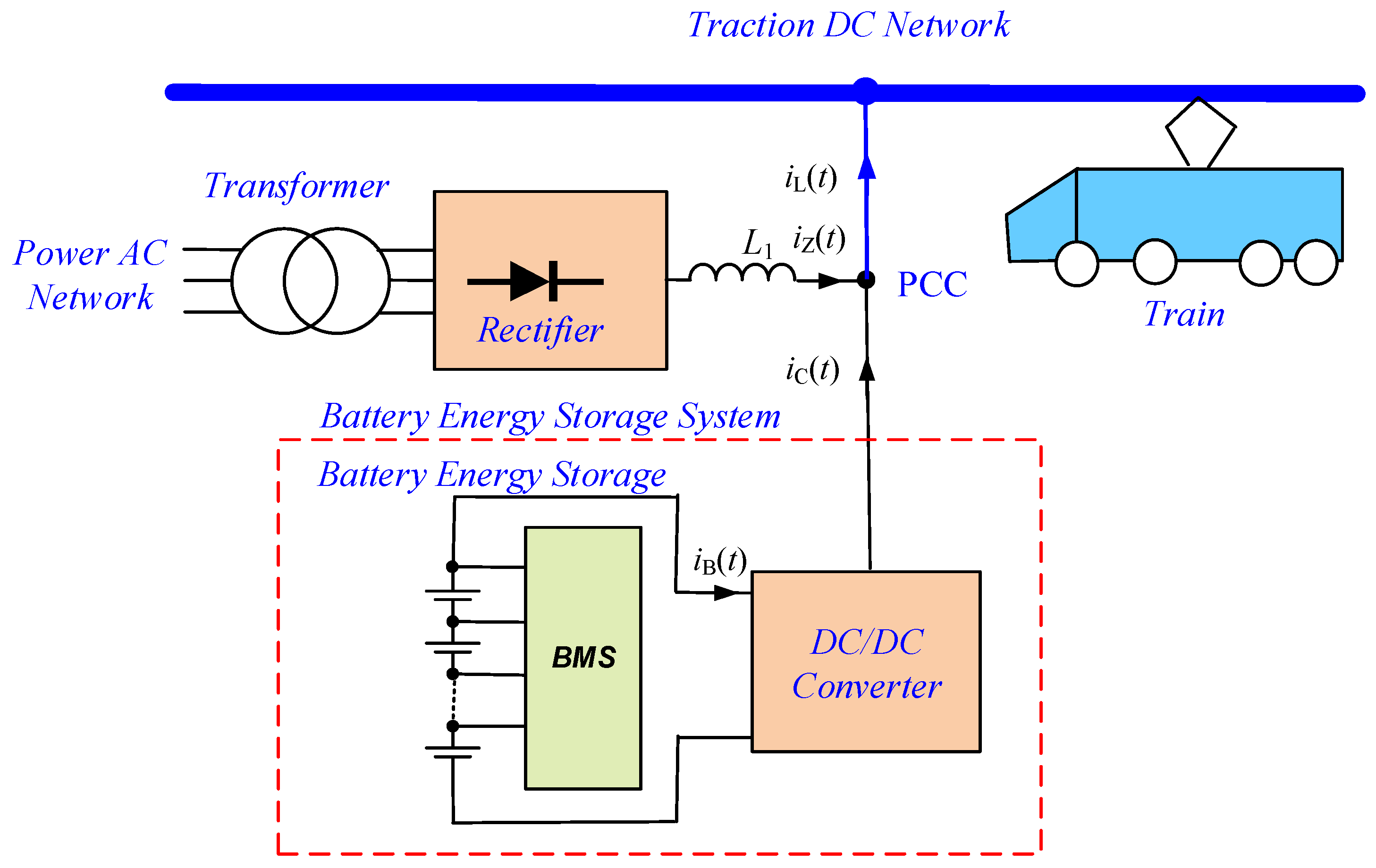
Based on such a system, the authors have developed a unique implementation on a European scale [3,4,5,6] called DROPT (the abbreviation was created from the Polish name Dynamiczna Redukcja Obciążenia Podstacji TrakcyjnejDynamic Reduction of Traction Substation Load), for which a simplified diagram is shown in Figure 2. The control algorithm of the BESS in the traction substation is aimed at peak power reduction, which has benefits in the following areas:
  • The railway operator incurs lower charges because it can reduce the contracted power requirements.
  • From the power grid point of view, power fluctuations are reduced and, consequently, voltage sags are reduced.
The small-scale model of a battery energy storage system, which was developed and described in this article, is part of a larger project. As a result of this project, a peak power reduction system for a traction substation, featuring a battery energy storage capacity of 1.2 MWh/5.5 MW, was developed and implemented.
The aforementioned implementation is being developed by the authors, and a more advanced algorithm is described in this article [4].
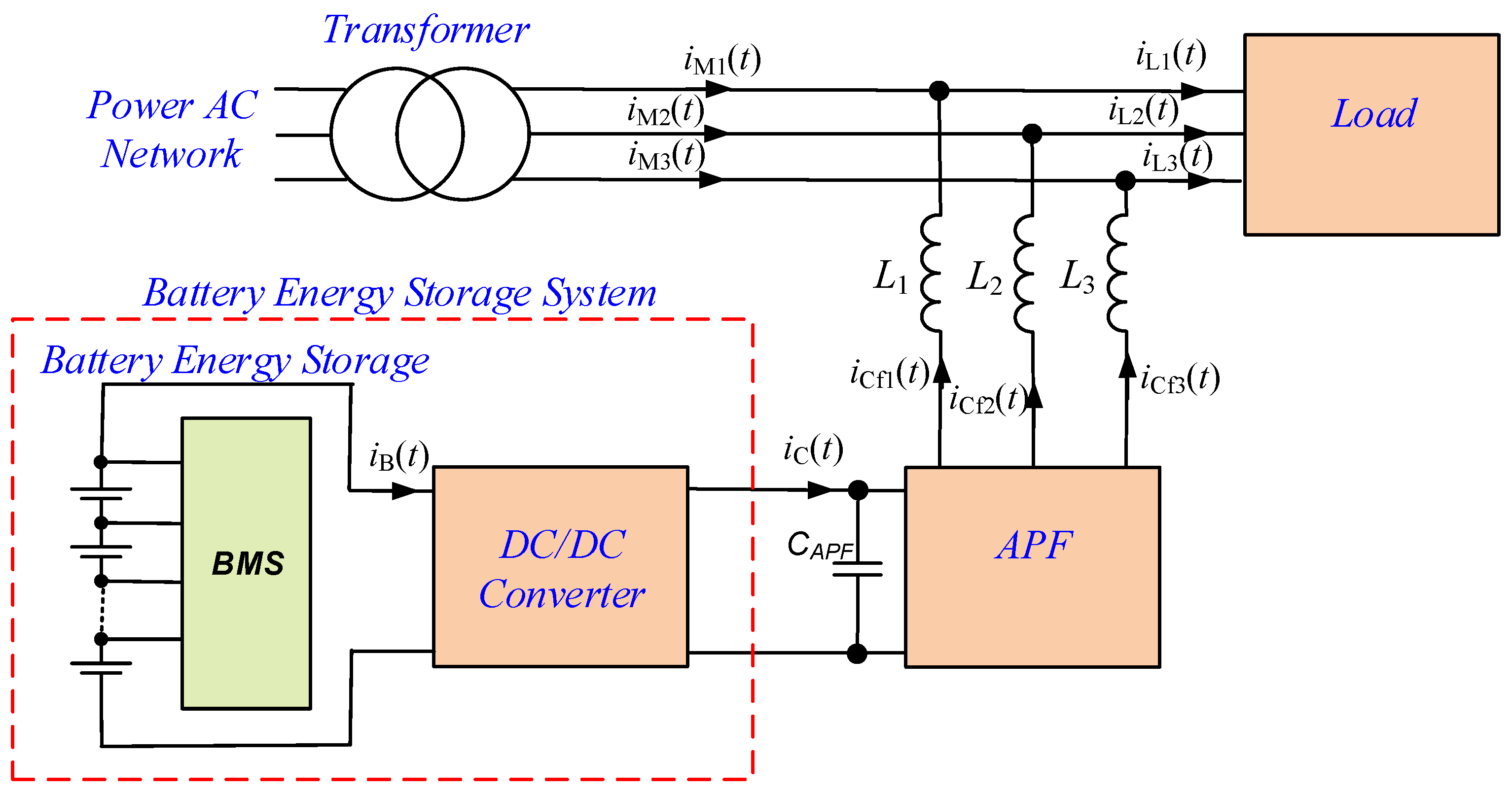
The small-scale BESS model can also be used in cooperation with an APF (active power filter) to reduce voltage sags and swells. In this case, less BESS capacity is required. A simplified diagram of APF with BESS is shown in Figure 3.

1.2. State-of-the-Art Battery Energy Storage Systems

Battery energy storage systems implemented in the traction substation and wayside energy storage systems (WESSs) [5,6,7,8,9] contribute to the reduction of peak power and energy consumption [10]. Peak power reduction impacts the 15 min average power reduction [11] and, consequently, reduces the contracted power at the traction substation [12]. The article [12] presents the concept of implementing a hybrid energy storage system (HESS) to reduce the demand for 15 min peak power, while [13] presents the control strategy for this system. A further effect of such a development is the reduction of fixed operating costs [14,15,16]. A very important aspect related to the implementation of BESS is optimal sizing and location [17,18,19,20,21] and control strategy [22]. In the article [23], a control strategy for a supercapacitor energy storage system (SESS) is presented, which is said to indirectly impacts peak power reduction and allow the use of regenerative energy. The article [24] describes a control strategy in a roadside BESS, based on energy transfer, in which the state of charge and power are tracked and dynamically adjusted. The control strategy envisages transferring regenerative energy generated during train braking from off-peak to peak periods. The possibility of recharging the BESS during off-peak periods is presented in the paper [25].
Energy storage in power systems, including their implementation, parameters, and properties, is extensively documented in the literature, particularly their use in AC power grids, as noted in references [26,27]. In contrast, there are significantly fewer publications on energy storage systems in DC traction networks. The known publications primarily focus on voltage stabilization along the overhead contact line and improving the voltage profile, especially through the use of hybrid energy storage systems (HESS) [28]. The authors are familiar with these technologies both from the literature and patented solutions. All known publications that describe methods for selecting and controlling energy storage facilities in traction substations and trackside energy storage systems (WESS) rely on simulation analyses, with some using actual measurement data as input.
The control strategy for this system is based on the following information: the actual voltage on the DC bus of the traction substation, the current flow (both on the DC line and directly to the BESS) and the current state of charge. This strategy facilitates the use of regenerative energy and allows for the recharging of the BES from the distribution grid to a predetermined state of charge during off-peak periods. The literature reveals a notable scarcity of hardware solutions for testing these algorithms, a fact that proves valuable when adapting the algorithm for practical applications.
In conclusion, the literature contains numerous examples and implementations of energy storage systems in railway traction, primarily focusing on improving voltage profiles and stabilization in the traction network, as well as enhancing energy efficiency through regenerative braking, as exemplified in [7]. However, most publications on the control methods of these systems, not only in traction networks, rely solely on simulation studies. Consequently, there is a notable absence of publications on the experimental validation of simulation research results in traction network energy storage. The small-scale battery energy storage system described in this article, which is used for testing algorithms aimed at peak power reduction, incorporates a bidirectional DC/DC buck-boost converter similar to those used in a full-scale system. Given the parameters of the full-scale system (5.5 MW/1.2 MWh), relying only on simulation and numerical analysis for control algorithm verification is insufficient. Furthermore, the novelty of the implemented control algorithm, which has been patented [29], necessitates and justifies a multi-stage verification process before implementation in a full-scale system.
The authors adopted the following design process: concept development, modeling, and analysis based on a simulation model, followed by verification using a small-scale model and eventual implementation in a full-scale system. Simulation analyses were grounded in real measurement data from the traction substation where the full-scale system was later installed. This approach, which combines actual data with simulations, is safer than relying solely on simulation models, and it significantly increases the likelihood of achieving positive results in the full-scale system. The modeling and simulation test results have been extensively documented in the literature by the authors in [4,5,6]. The natural progression from here is to develop a small-scale model and conduct experimental verification of the developed algorithms. In this article, the authors describe the experimental setup of a small-scale energy storage model for the experimental verification of algorithms aimed at peak power reduction.

2. DC/DC Converter

In the experimental model, the bidirectional buck-boost dc/dc converter has been used (Figure 4). The implemented DC/DC converter and control methods are well known and are widely described in the literature [30,31]. Depending on the method of controlling the switches (S1 −- S4), the converter enables bidirectional energy flow (from side A to B or from B to A) and control of the output voltage value. A few basic control methods are typically used to control the DC/DC converter, such as the buck-boost method, the buck + boost method, the buck + boost method with synchronic switching or the buck-boost method with phase shifting.
The switching states (switching sequences) of the semiconductor switches of the DC/DC converter for the selected most popular control methods are shown in Table 1.
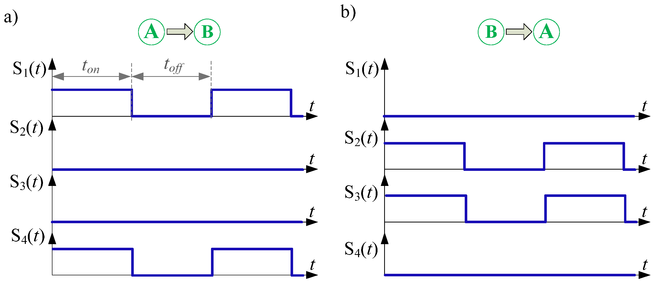
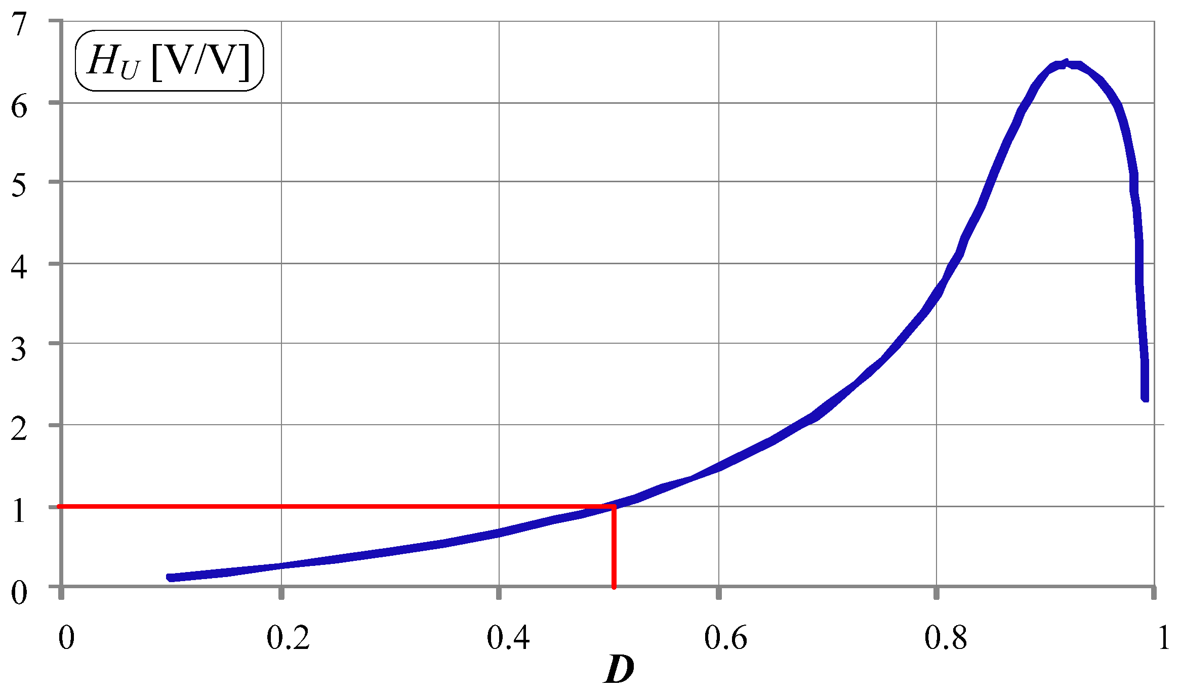
Exemplary time waveforms of gate signals and voltage transmittance (voltage gain) as a function of pulse duty factor D for the buck-boost control method are shown in Figure 5 and Figure 6, respectively. The characteristics have been obtained from a simulation model of the DC/DC converter.
As can be seen, this control method is very simple. In each operation mode, only two switches are always in operation. The voltage gain characteristic (Figure 6) is the same, regardless of the direction of energy transfer in the converter (A → B, B → A). The voltage gain characteristic is non-linear across the entire range. A gain (voltage transmittance) equal to 1 is achieved for the pulse duty factor D = 0.5.
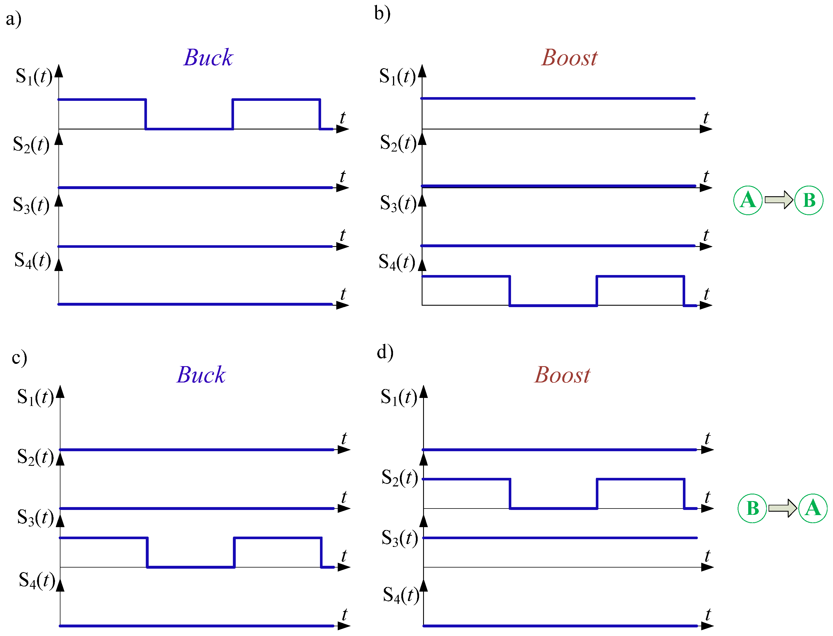
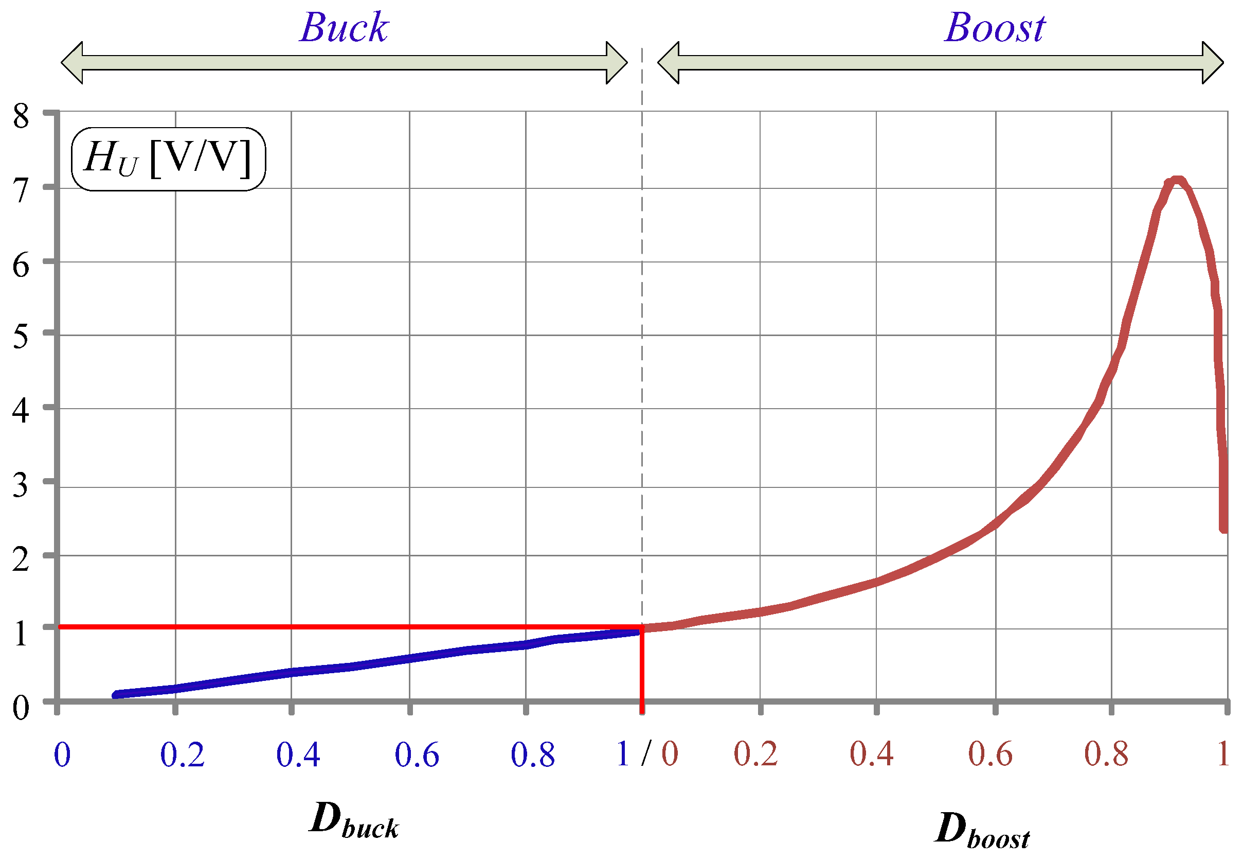
Exemplary time waveforms of gate signals and voltage transmittance (voltage gain) as a function of pulse duty factor D for the buck + boost control method are shown in Figure 7 and Figure 8, respectively.
The control strategy of the buck + boost method is different in comparison to the buck-boost one. During buck operation mode, there is always only one switch in operation (i.e., switching with pulse duty factor D) (see also Table 1). During boost operation mode, there are two switches in operation: one switch is constantly switched on, while the second one switches according to the pulse duty factor D. As is visible in Figure 8, the voltage gain characteristic is linear in buck operation mode and nonlinear in boost operation mode.
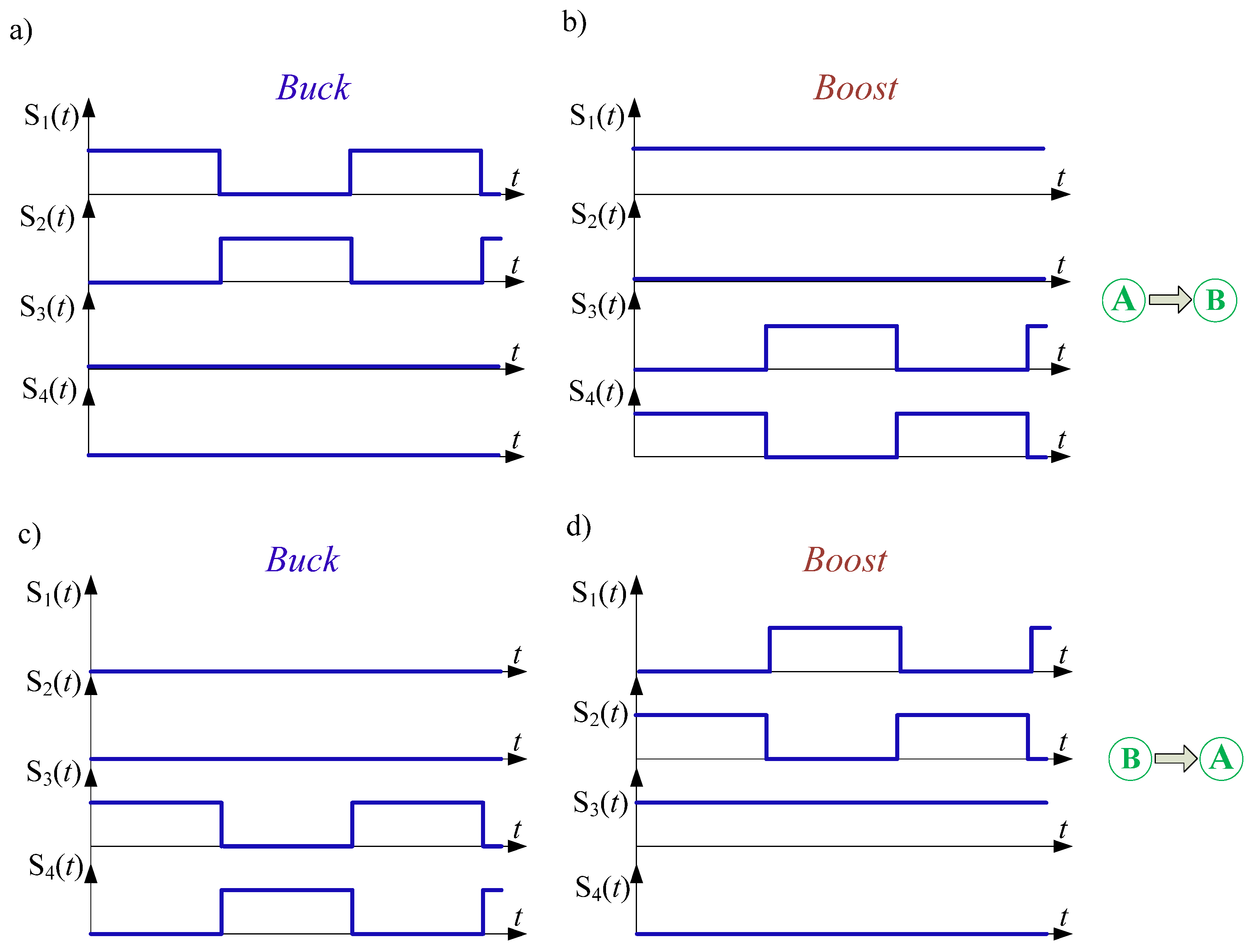
Exemplary time waveforms of gate signals for the buck + boost method with synchronic switching are shown in Figure 9. The voltage transmittance is the same as in the buck + boost control method (see Figure 8).
As is visible in Figure 9, during buck operation mode, there are two switches in operation, and their signal gates are reversed in phase. Additionally, in boost operation mode, a third switch is constantly switched on.
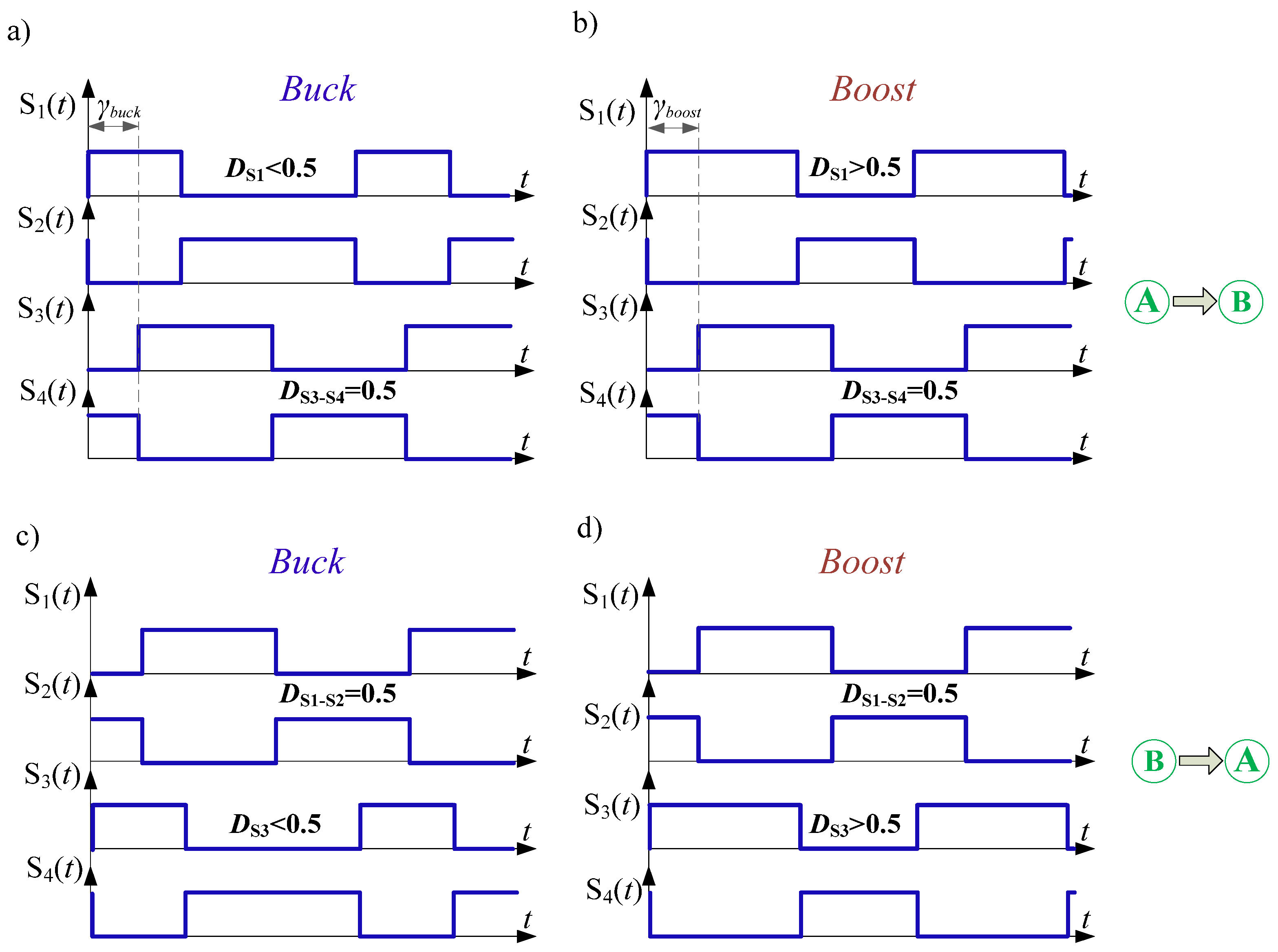
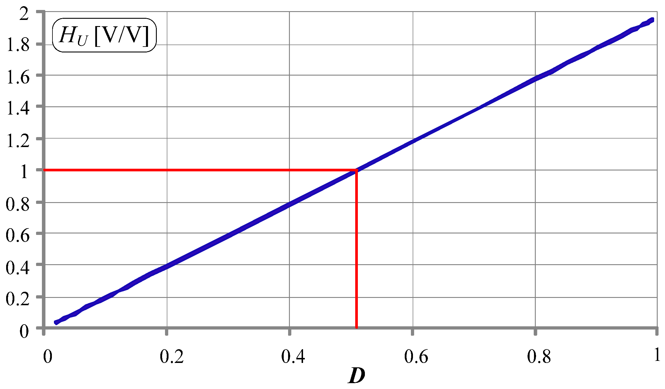
The buck + boost control method with phase shifting is more complex than the previous methods (Figure 10), but it gives a linear characteristic of voltage gain (Figure 11).
The voltage gain, depending on energy flow direction, can be described by Equations (1) and (2).
H U A B = D S 1 D S 3
H U B A = D S 3 D S 1
As can be seen in Figure 11, the voltage gain characteristic for buck + boost control method with phase shifting is linear, but the maximal voltage gain is only twice.
Taking into account the properties of various control methods of bidirectional DC/DC converters, in the laboratory model used, the buck-boost control method is implemented.

3. Laboratory Model of DC/DC Converter

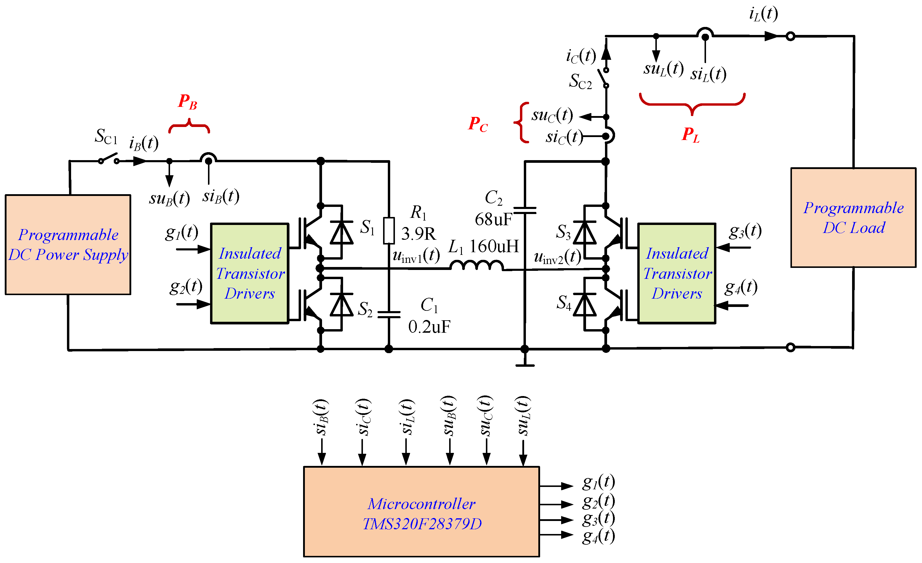
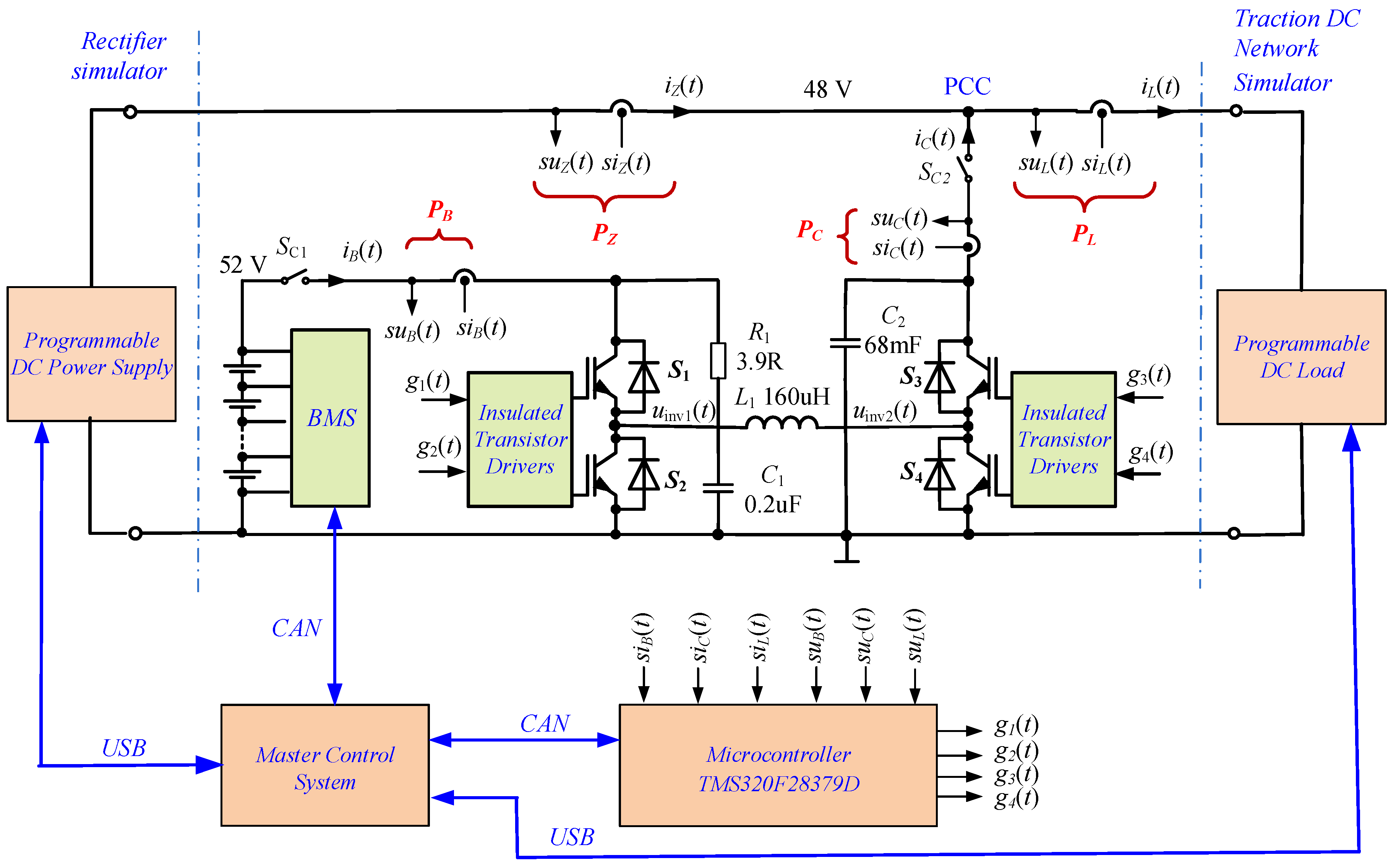
In order to verify the developed control algorithms for battery energy storage systems, a laboratory model (hardware simulator) of the system was designed. The designed hardware simulator is a so-called small-scale model with much lower power compared to real systems. In the low-power experimental model, the DC voltage (corresponding to the rectifier unit side) is assumed to be 52 V, and the load current is up to 100 A. The rectifier side is simulated by an advanced programmable laboratory DC power supply EA-PSI 9200-210 from EA Elektro-Automatik Group (Viersen, Germany). The load for the system under test is an advanced programmable DC load IT8930A-1200-1200 from ITECH (Taiwan). The simplified schematic diagram of the laboratory model of bidirectional buck-boost DC/DC converter is shown in Figure 12. The main parameters and elements of the system are described in Table 2.
As power electronic switches (S1, S2, S3, S4), two fast IGBT modules, FF100R12RT4 from Infineon (Erlangen, Germany) are used (each module contains two transistors). To achieve galvanic separation, two dual-channel IGBT gate drivers with adapter boards “SKYPER 32 PRO R” from Semikron (Nürnberg, Germany), are used. In the system, a low switching frequency of the transistors equal to fC = 8 kHz is applied.
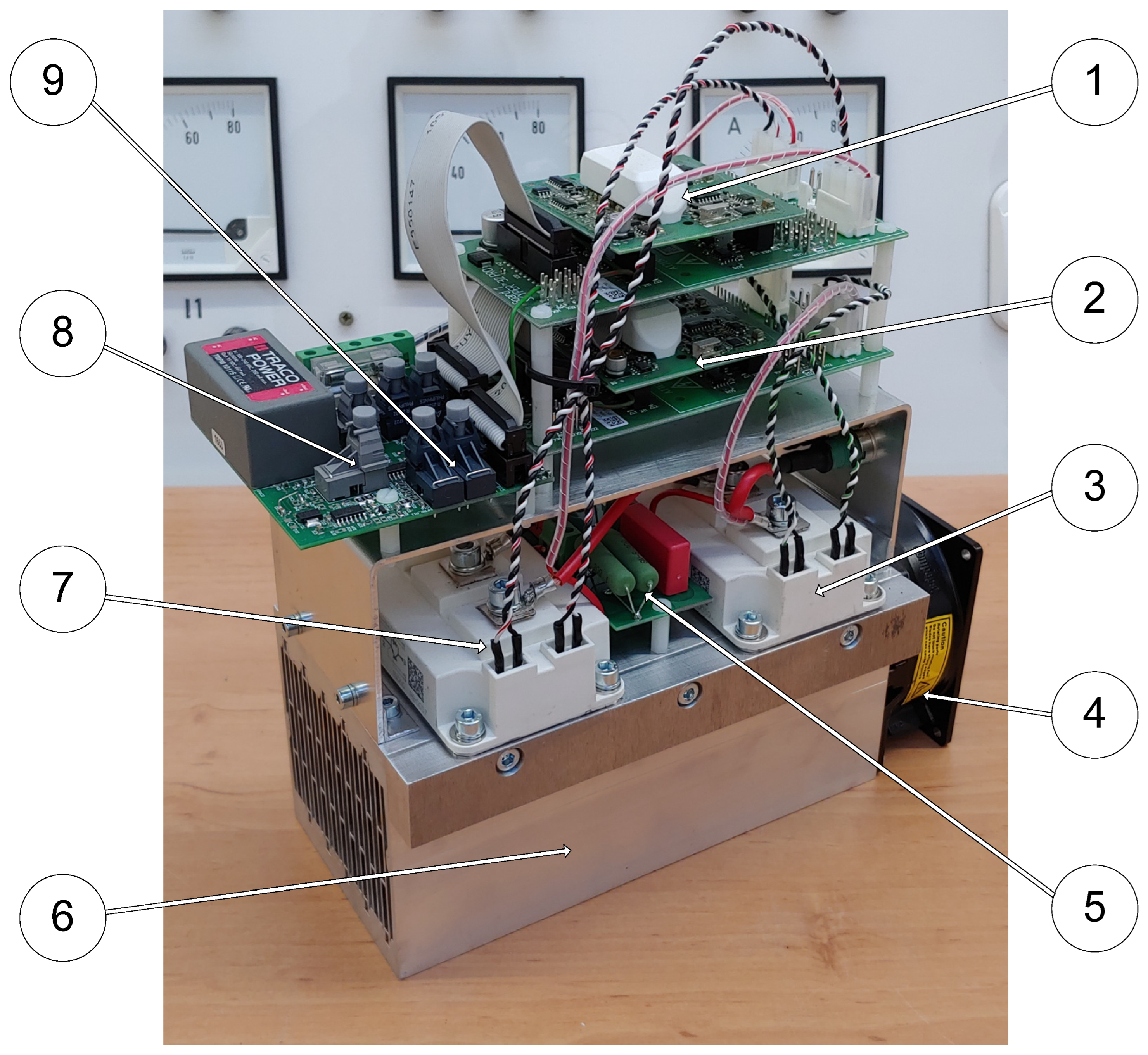
The general view of the experimental model of the bidirectional buck-boost DC/DC converter power module is shown in Figure 13. The laboratory model of the DC/DC converter contains two dual channel IGBT drivers, (1) and (2), for two IGBT modules, (3) and (7). The IGBT modules are mounted on a heatsink (6) with a fan (4) for cooling. The transistor’s control signals are sent from the microcontroller via fiber optic couplers, (8) and (9). To provide overvoltage protection for the transistors, an RC snubber circuit is used (3).
The control circuit is based on a very advanced microcontroller TMS320F28379D from Texas Instruments (Dallas, TX, USA). In order to simplify the process of commissioning the laboratory model of the system, a Texas Instruments (Dallas, TX, USA) LunchPad TMS320F28379D development module is used [32,33]. This module is equipped with an XDS100V2 emulator chip allowing for the transfer of programs from a computer and programing flash memory using the USB interface. In addition, the emulator can be galvanically isolated from the microcontroller, which increases the security of the software launch process. The C language is used for programming in the Texas Instruments Code Composer Studio v. 11 environment. The microcontroller module is also equipped with a galvanically isolated CAN interface.
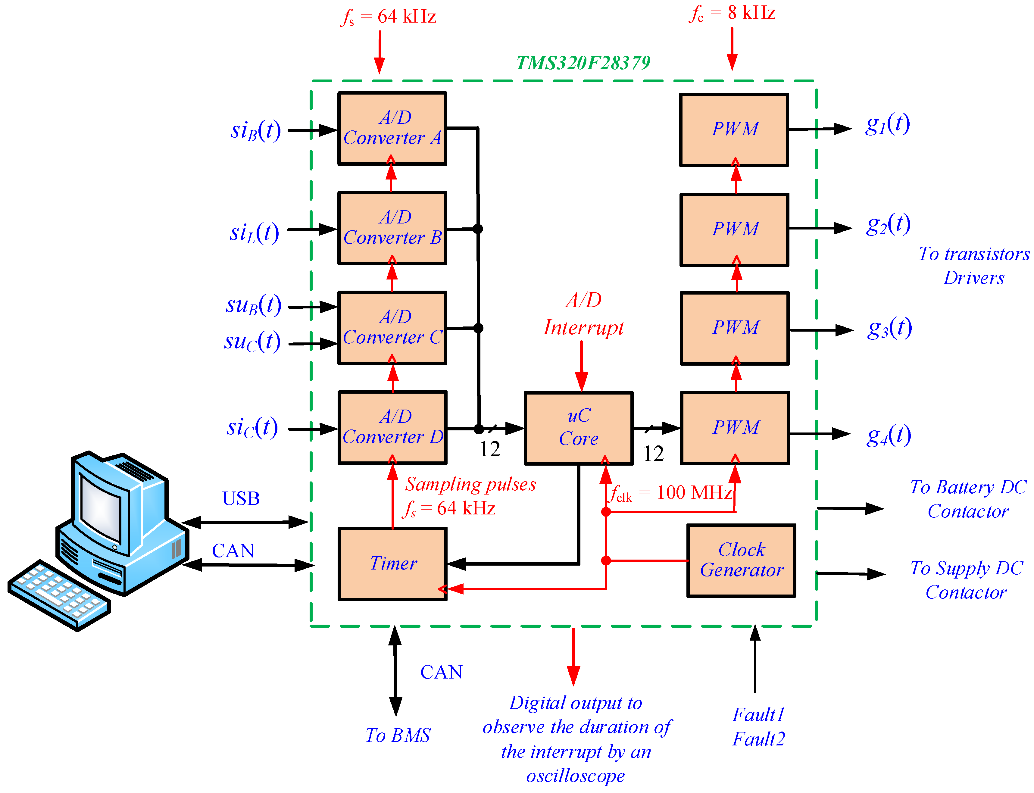
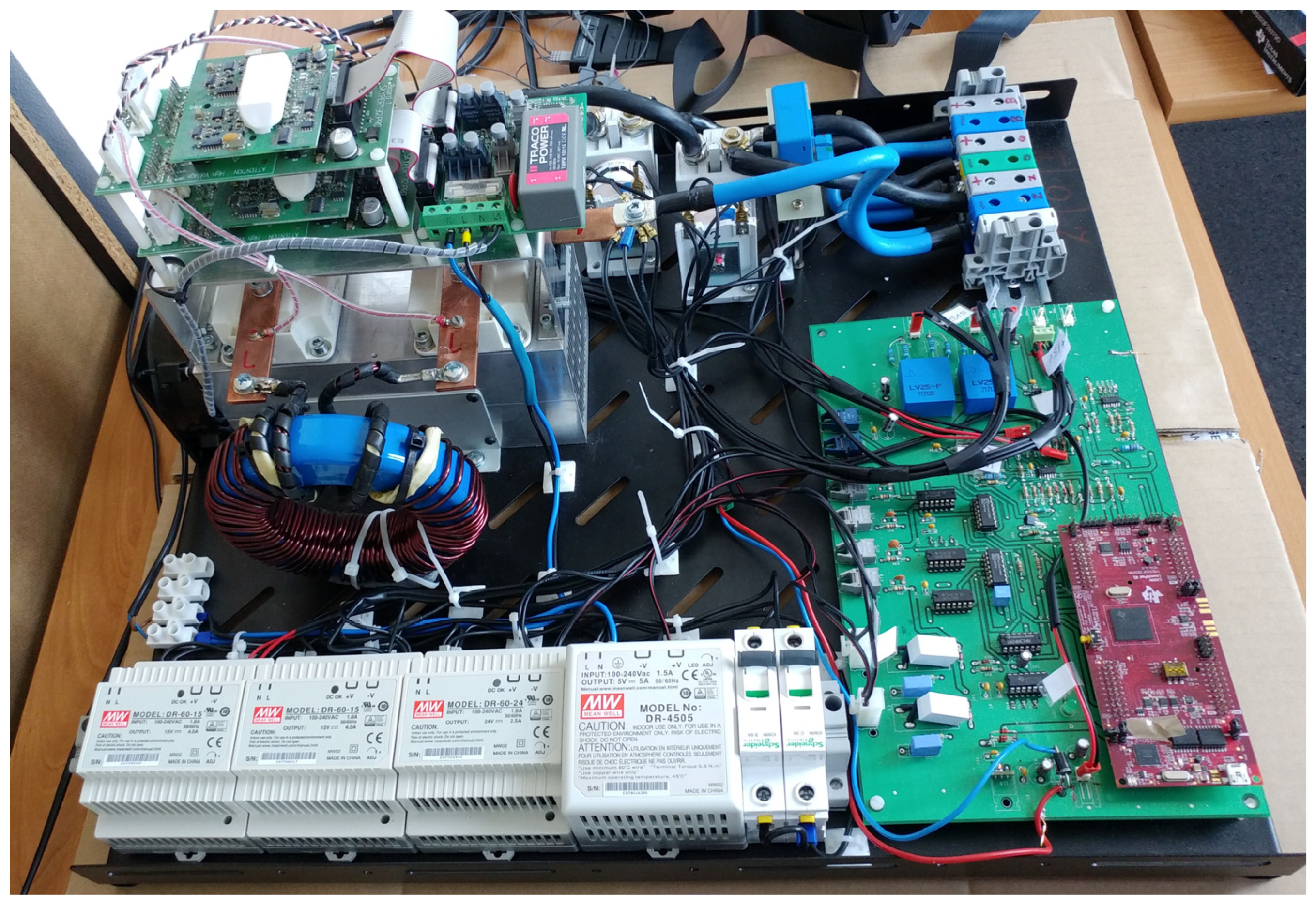
A simplified block diagram of the control system is shown in Figure 14. The main component of the control system is the microcontroller module. The control system controls two DC contactors (Figure 12), namely SC1 for switching on the magazine and SC2 for the power supply. The pulses that control the converter transistors are generated by the processor’s PWM modulators and are then transmitted to the transistors via optical fibers. Error signals Fault1 and Fault2 from the transistor modules are also transmitted via optical means. General view of the laboratory DC/DC converter is shown in Figure 15.

Analog Signal Sampling

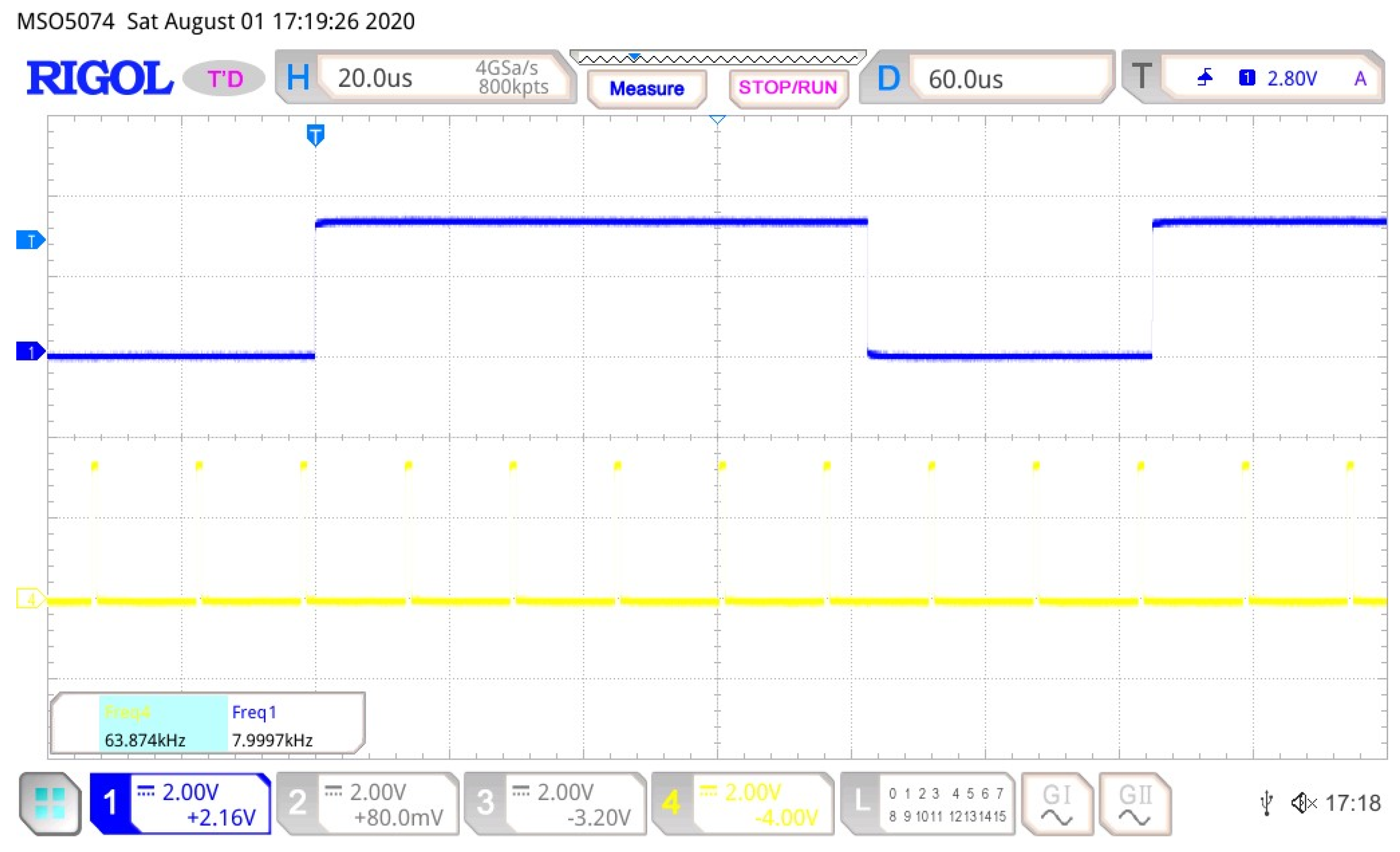
Processing signals such as those in DC/DC converters is not straightforward. For accurate determination of average current and voltage values, it would be required to use a processing system with a very high sampling frequency, in accordance with the signal sampling theorem. In the system in question, synchronous sampling was used, which allowed reduction of the sampling frequency to eight samples per PWM period. The simulation studies conducted by the authors confirmed the sufficient accuracy of this solution. The waveform of the sampling process is shown in Figure 16.
To measure the currents and voltages in the power system, galvanically isolated current and voltage transformers of the LEM type are used. The analog signals are then converted into digital form by the processor’s A/D converters.
The conversion of eight analog signals is necessary to control the system. Only five signals were selected for A/D conversion, while the conversion of the supply line voltage and current is omitted. The best solution would be to use A/D converters with simultaneous sampling of signals. Unfortunately, the TMS320F28379D has only four 12-bit A/D converters with simultaneous sampling [32]. Due to this, a hybrid solution was implemented in the control system, which combines simultaneous and sequential sampling techniques.
The process of sampling all signals consists of eight cycles, described in Table 3.
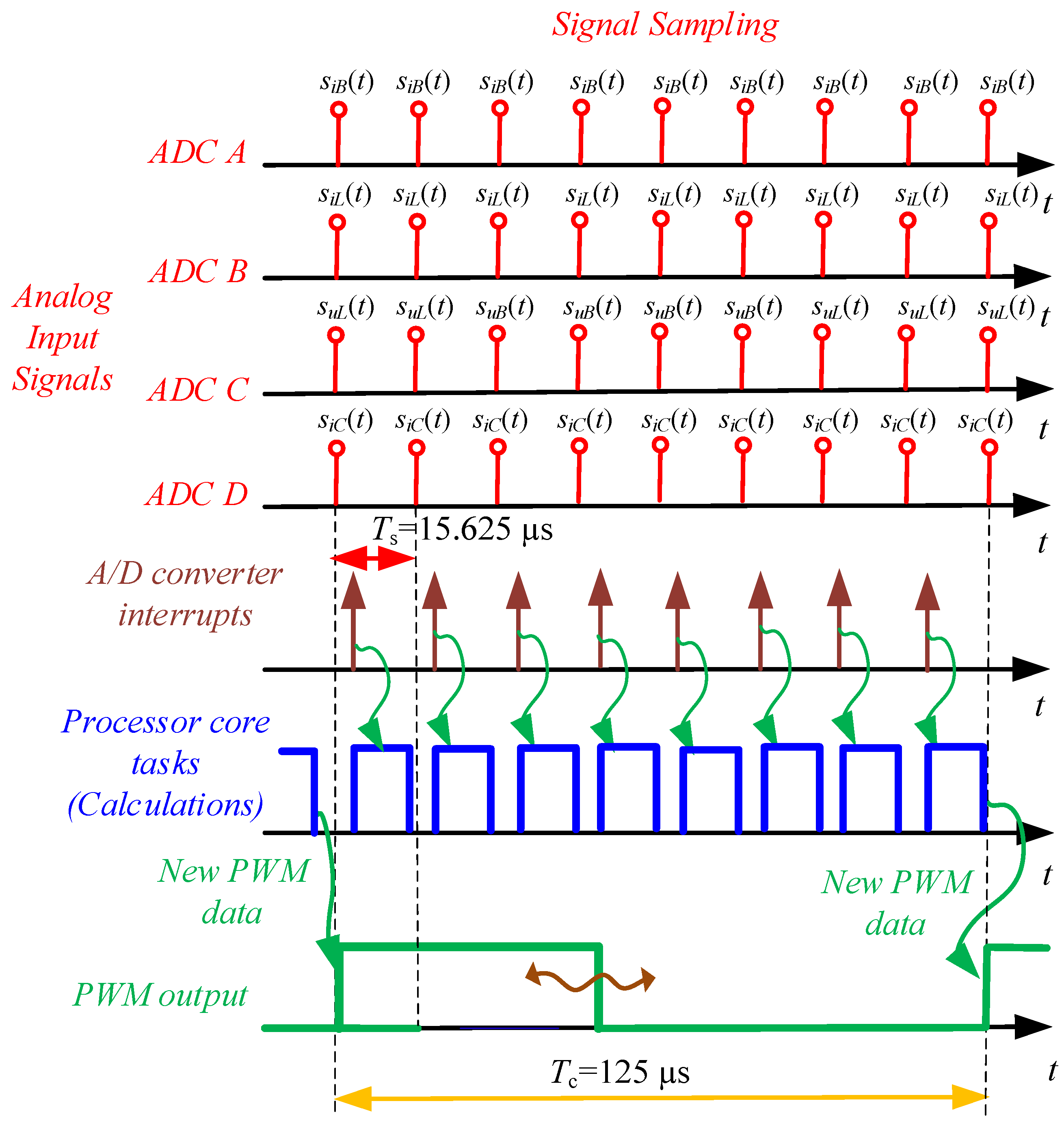
The sampling frequency of current signals was assumed to be eight times higher than the switching frequency of the DC/DC converter transistors, with fs set at 64 kHz. It is crucial that the sampling process be initiated by an internal counter (notably by hardware, not software) in the microcontroller, maintaining a constant and stable sampling rate of fs = 64 kHz. This approach minimizes jitter, which can deteriorate the signal-to-noise ratio (SNR) [34,35,36,37,38,39,40]. The entire control algorithm is executed in the interrupt routine triggered by the A/D converter. The timing diagram of the data flow in the digital controller is illustrated in Figure 17. New data from the A/D converters generate a new interrupt, with the time interval between interrupts equal to Ts. Therefore, all calculations must be completed before the arrival of the next interrupt, as depicted in Figure 17. Data are transmitted to the PWM modulator once every eight sampling periods, allowing for more complex calculations to be sequentially performed during the next eight interrupts.
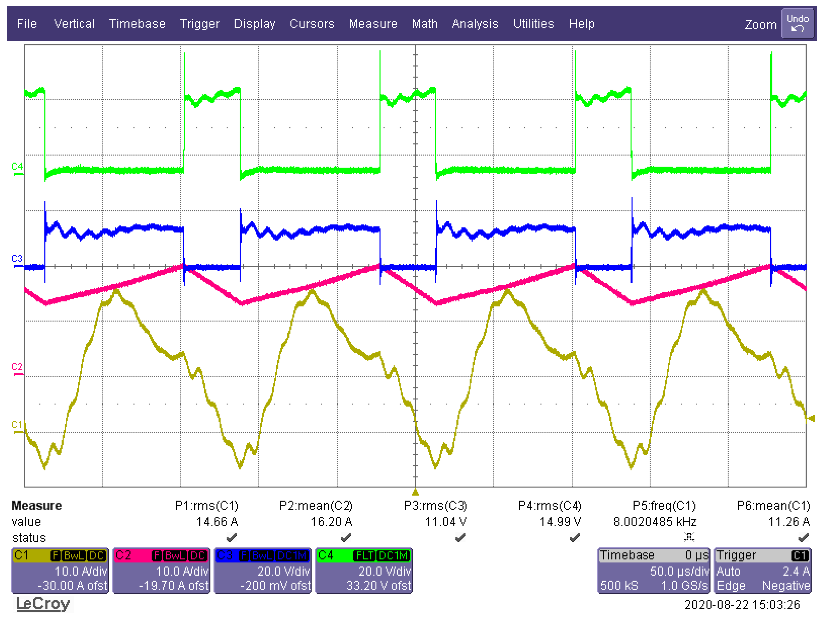
Exemplary voltage and current waveforms of the DC/DC converter system for the pulse duty factor D = 0.7 are shown in Figure 18.
In Figure 18, the overvoltage associated with the transistor commutation process is visible on the time waveform (channel 4). Originally, relatively slow IGBT transistors of the SKM160GM12T4G from Semikron (Germany) were used. In order to eliminate overvoltage, it was necessary to use a snubber circuit, in which large energy losses occurred. By using faster transistors, such as FF100R12RT4 from Infineon (Germany), this problem was reduced to the level shown in Figure 18.
The system uses a relatively low switching frequency of 8 KHz to be identical to that of the target high-power circuit. Similar criteria were used to select the size of the energy storage.
The laboratory model is used to confirm the entire concept of the system on a power scale of 1:1000.

4. Laboratory Model of Battery Energy Storage System (BESS)

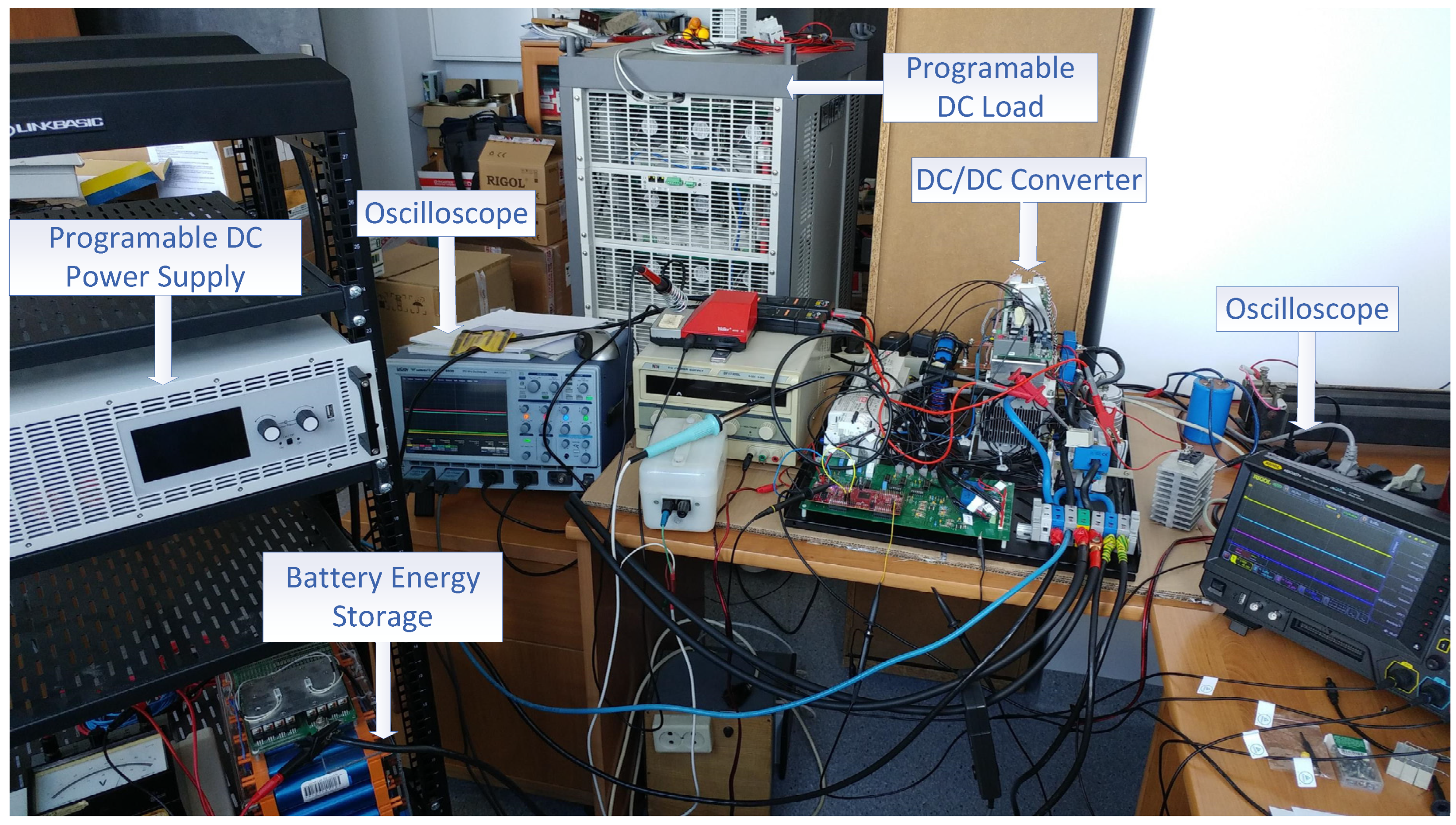
The simplified block diagram of the model of the BESS system is shown in Figure 19. A battery energy storage with a capacity of 1 kWh and a voltage of 52.8 V is used, consisting of thirty-two LiFePo4 (lithium iron phosphate battery) cells. For battery protection, a battery management system (BMS) is used. It allows for battery protection in order to prevent operations outside its safe operating area, battery monitoring by estimating the battery pack’s state of charge (SoC) and state of health (SoH) during charging and discharging and battery optimization, thanks to cell balancing, which improves the battery’s life and capacity. The state of the battery is monitored by the microcontroller through a CAN interface. The view of the laboratory setup of the testing circuit is shown in Figure 20.
The entire system is managed by the master control system. The laboratory DC power supply, EA-PSI 9200-210, and the advanced programmable DC load, IT8930A-1200-1200, are connected via USB interface. Meanwhile, the microcontroller is connected via a CAN interface.
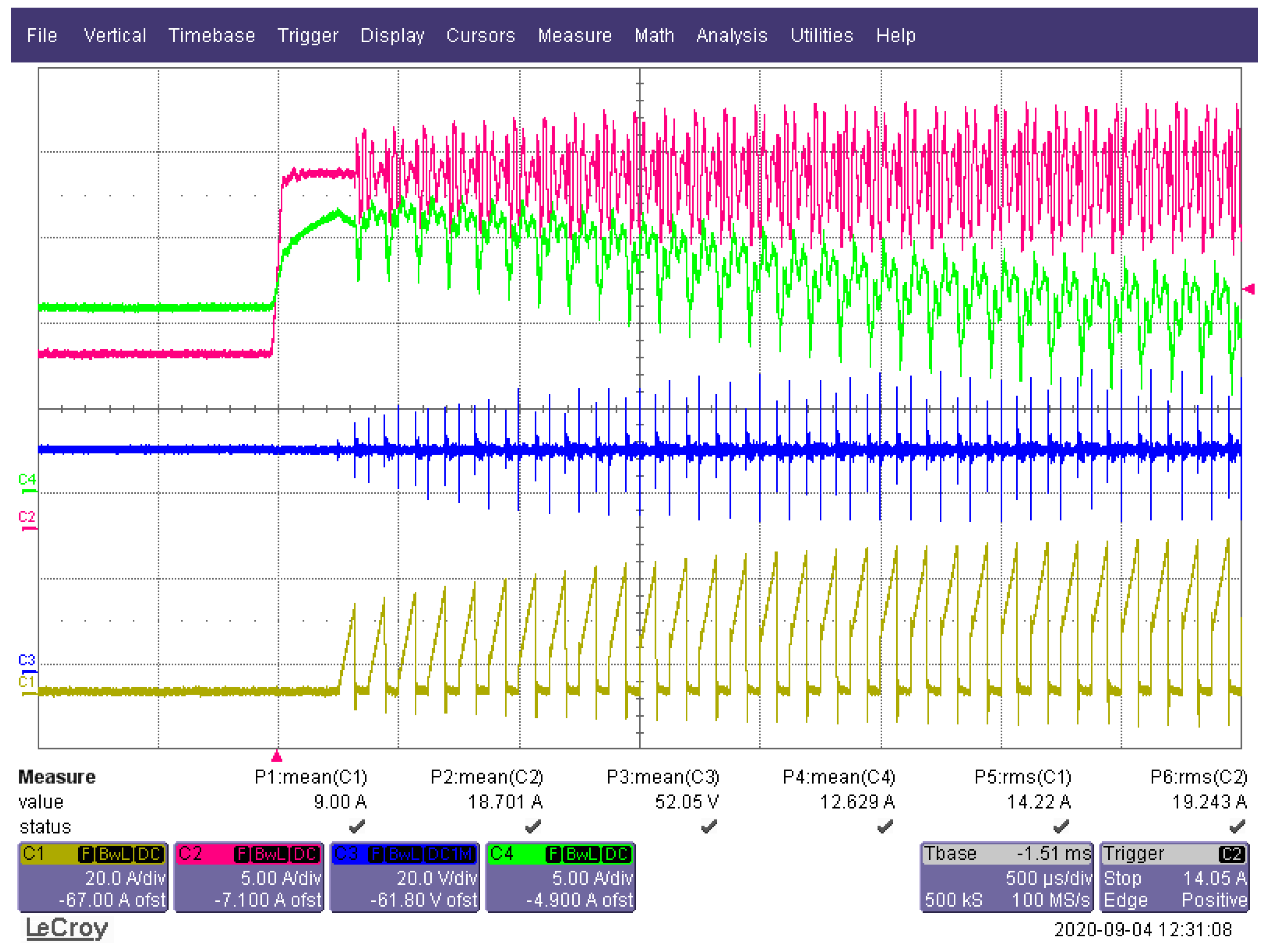
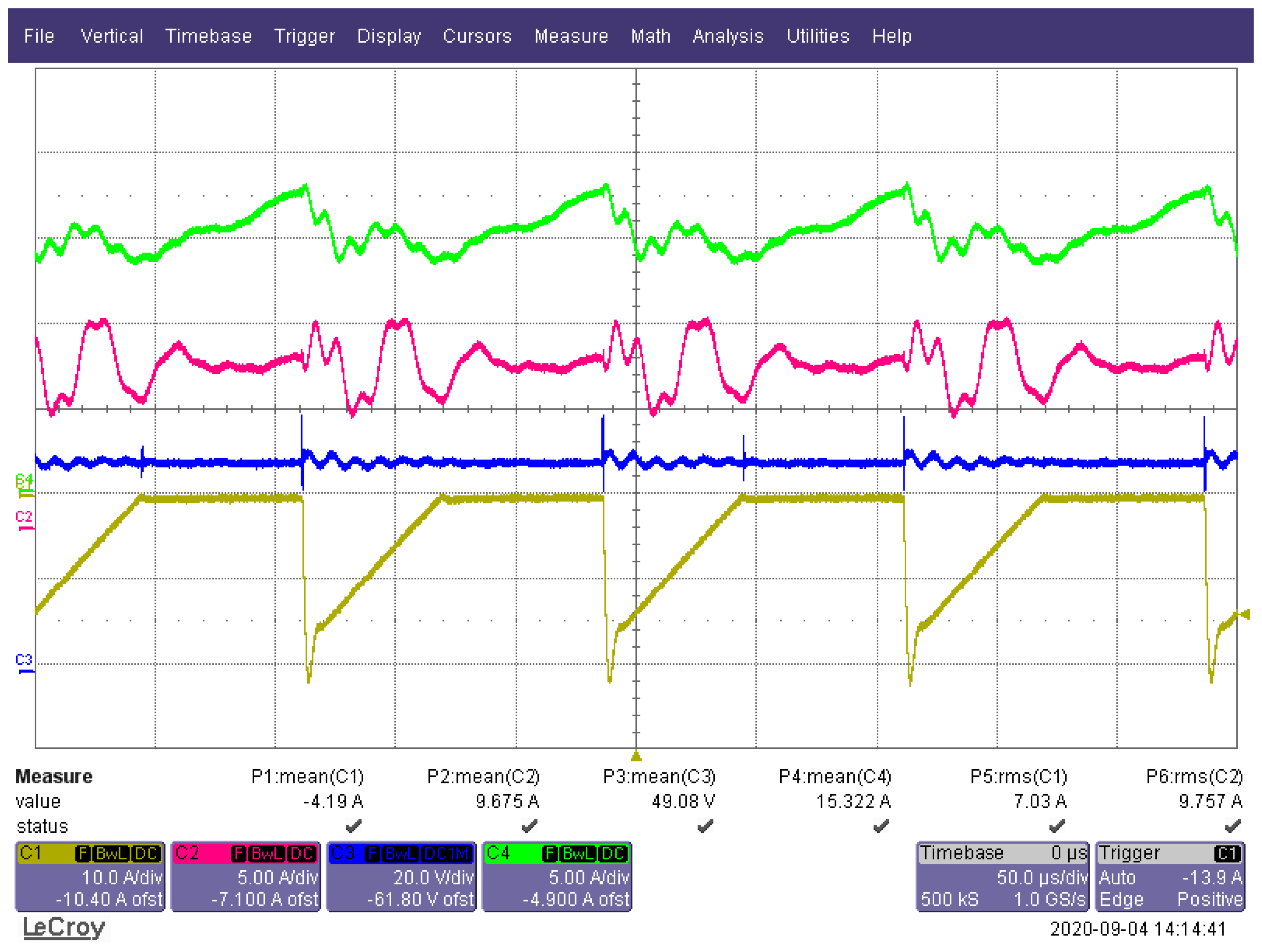
Exemplary experimental waveforms for the laboratory model of the energy storage system during a step change of load current and battery charging for PB = −206 W are shown in Figure 21 and Figure 22.

5. The Tested Algorithm

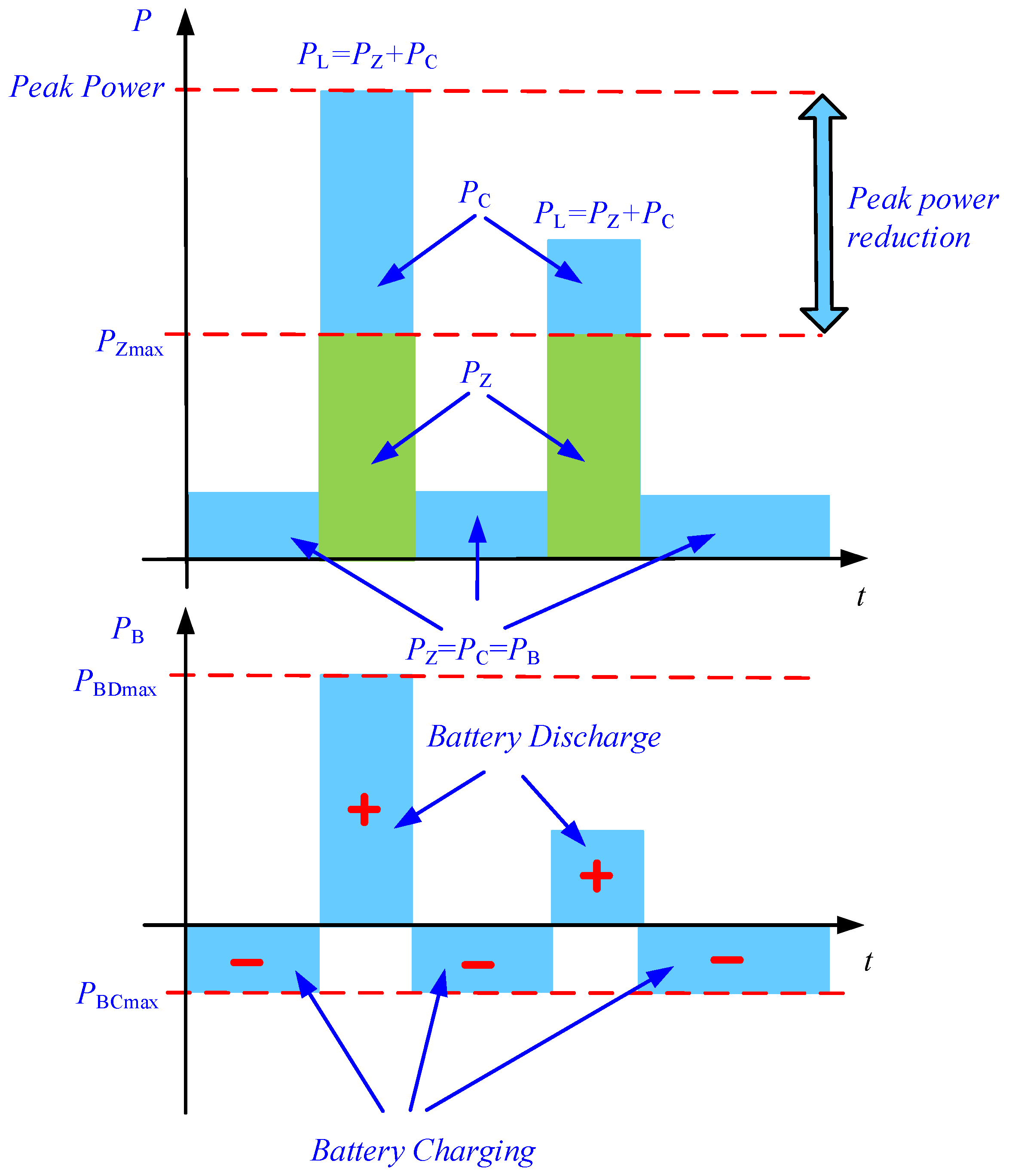
Figure 23 shows an idealized illustration of the power peak reduction process through the energy storage system. In the system, the power drawn from the supply is limited to PZmax. For a load power greater than PZmax, a DC/DC converter is activated, allowing for the transfer of energy from BESS to the load. Meanwhile, the BESS is charged during low energy consumption from the power supply system.
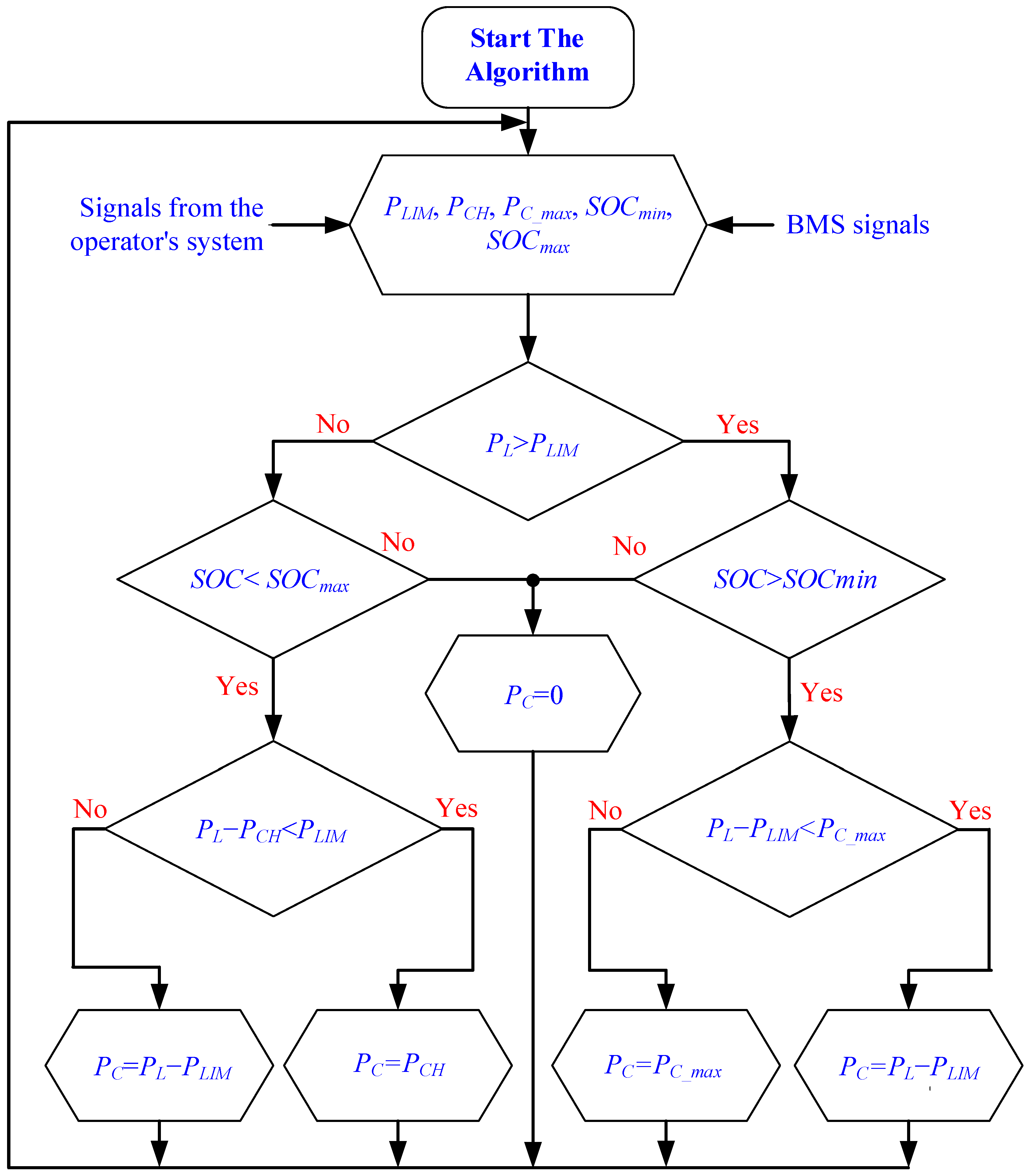
The principle of operation and the control method of the energy storage system for peak-power reduction at the traction substation are presented in Figure 23 and Figure 24. This control algorithm has been patented [29] and is implemented in a full scale system [3]. This algorithm has been developed with additional functions of fault-tolerant control and was widely described in [5]. The limitation of the traction substation load power at the connection point (PCC) is based on direct measurements of the traction substation load power (PL) and is carried out with the power reduction threshold value (PZmax) intentionally set by the user (by the traction system operator). As a result of comparing the instantaneous value of the load power at the traction substation on the traction network side (PL) with the value of the power reduction threshold (PZmax), the instantaneous power value (PC) of the energy storage system is determined and forced. If the load power of the traction substation on the side of the traction network is higher than set value of the power reduction threshold (PL > PZmax), the battery energy storage is discharged with the positive power (see Figure 23). Discharge power is the difference between the instantaneous values of the load power at the traction substation and the value of the power reduction threshold (PC= PLPZmax), but not greater than the maximum power of the energy storage system (PCPBDmax). If the load power at the traction substation on the traction network side is below the set value of the energy storage charging power limitation (PL < PZmax), the storage process is loaded with the negative power of the energy storage system limited to the charging power limitation (PBCmax). If the sum of the storage charging power limit values (PCH) and the current load power at the traction substation (PL) falls below the set value of the power reduction threshold, charging will occur with the storage power limited to its maximum negative value (PC = PBCmax) (see Figure 24).Otherwise, the power with which the energy storage is charged is reduced so that the sum of the power of the energy storage system and the load power at the traction substation remains below the power reduction threshold.
Optionally, the value of the power reduction threshold (PZmax) on the traction substation side of the connection point (PCC) is determined based on the analysis of the average daily load power values at the traction substation, measured over a period of at least one week, and it is set by the user to be no less than the maximum average daily load power value at the traction substation for this period. The storage charging power limit value may be assumed to be no greater than one tenth of the maximum discharge power value (0.1 of PBCmax) of the energy storage system.

6. Results of Laboratory Tests

The main task of the laboratory tests is the experimental verification of the BESS control algorithms for reducing peak energy consumption from the power supply system.
During this research, currents iZ(t), iB(t), iL(t) and voltage uL(t) were recorded. The powers were determined analytically based on the measured currents and voltages. The results of oscilloscopic measurements, saved in a text file, were subjected to analytical calculations to determine the average values over the switching period, and powers were derived from these calculations. The analysis mainly focused on dynamic states during which abrupt load changes were made, with a given power reduction threshold. This approach allowed for a clear presentation of the obtained results.
Figure 25 shows an example of the time waveforms of PC, PZ and PL power during a step change in load power from 400 W to 600 W, with the reduction threshold set slightly below 400 W. As long as the load power PL does not exceed the preset reduction threshold, the BESS system does not participate in power balancing. In the second millisecond (Figure 23), there is a step change in the load power to 600 W. As soon as the power of the reduction threshold is exceeded, the BESS system begins to replenish the missing energy. A momentary, transient state characterized by overshoot and a temporary increase in power on the supply side (PZ) is clearly visible. This transient lasts less than a millisecond, after which the load energy is the sum of the energy from the power supply and from the BESS system.

7. Discussion and Conclusions

This paper contains a description of a hardware simulator for verifying the control algorithms of the DROPT system [3,4,5]. The verification of the control algorithms was carried out by means of experimental tests conducted on a laboratory model (hardware simulator) of the DROPT system [4] on a power scale of 1:1000 (5.5 kW). The experimental model is based on converter modules with IGBT transistors and energy storage with lithium cells made using LiFePo4 technology. The control circuit is based on an advanced TMS320F283379D microcontroller from Texas Instruments.
Also noteworthy is the microcontroller module used, which effectively executes the control algorithm. The capability for simultaneous sampling ensures the accurate measurements of currents and voltages within the system. Moreover, the control system incorporates robust digital signal processing synchronization solutions that achieve very low jitter and eliminate beat signals, a phenomenon often encountered in power electronic circuits.
This description of the control system could guide readers in constructing similar systems. Such detailed explanations are frequently overlooked, potentially leading to errors. Therefore, we believe that the following is the added value of our paper: it provides readers with a clear pathway to successfully implement their control circuits.
To power the experimental model of the DROPT system, a specialized programmable DC power supply is used, simulating the power supply of the system from the rectifier units. A programmable DC load is used as the load of the system, simulating the traction DC network. In addition to detailed descriptions of individual elements of the hardware simulator, this report presents the results of experimental tests of the bidirectional buck-boost DC/DC converter, as well as the time waveforms of voltage and currents in the DROPT system model for the charging and discharging mode of the energy storage system. In the experimental model developed for the purposes of this research, currents and voltages in the system were recorded, then analyzed, and both the instantaneous and average values of the currents and power in the system were determined. Experimental tests carried out on a laboratory model (hardware simulator) showed the algorithm’s effectiveness in reducing peak power consumption from the power source. It should be emphasized that although the selection of regulator settings in the control system was not the subject of analysis, very good dynamic properties of the system were achieved. A response time of a few milliseconds, compared with the dynamics of the real system which operate at the level of single seconds, guarantees the correct operation of the control algorithm.
The experimental results presented constitute a positive verification of the research conducted during the stages of theoretical and simulation analyses [4]. It should be emphasized that the implementation of the DROPT system facilitated the following:
-
A reduction in ordered power and electricity charges;
-
A decrease in the power and size requirements of transformer stations and transmission lines, as well as a reduction in electricity transmission and transformation losses;
-
A reduction in power fluctuation in the power grid.
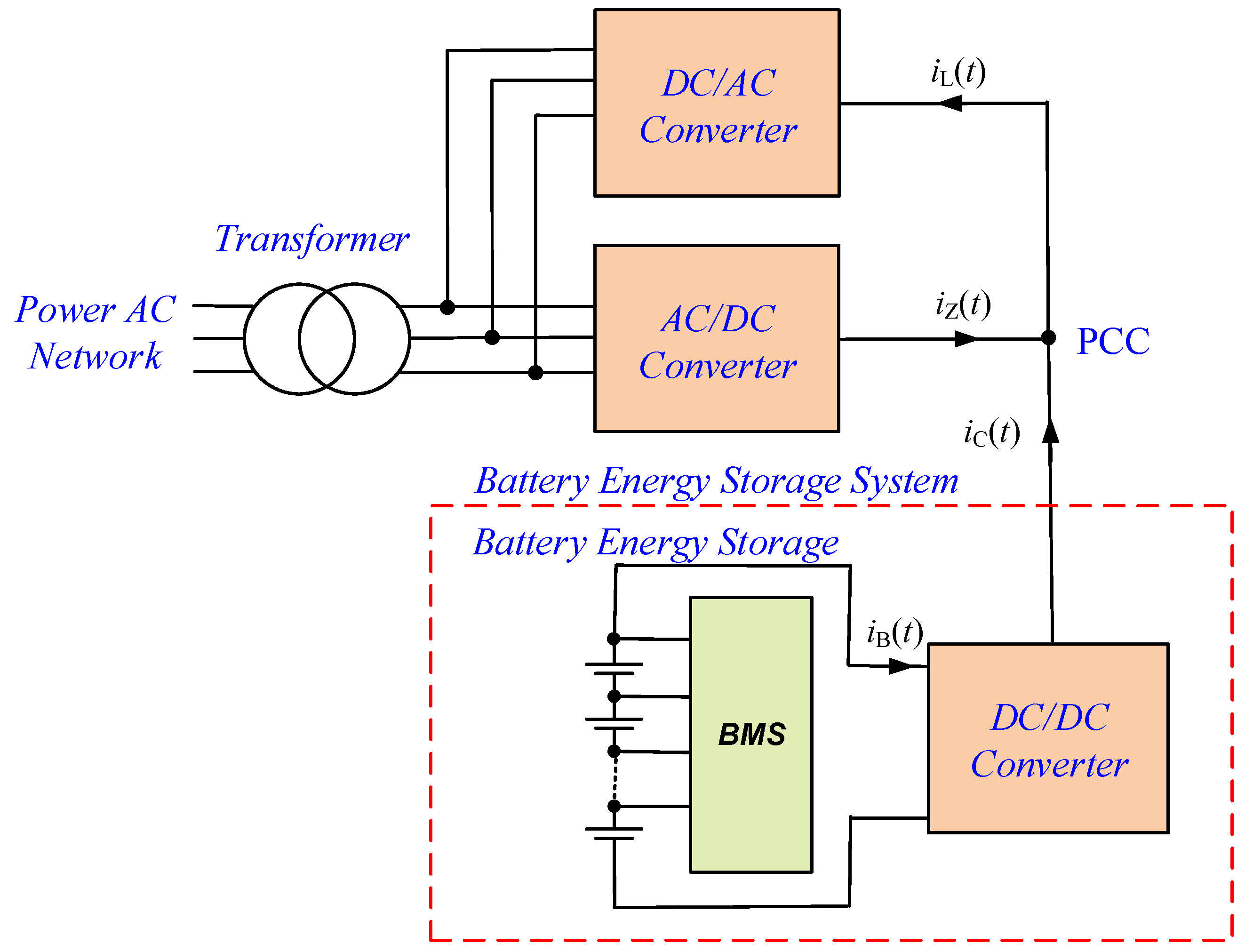
The test system uses typical laboratory instruments, such as a programmable DC power supply and a programmable DC load. In the next version of the test stand, we plan to use a programable AC/DC converter and a programmable DC/AC converter, thanks to which it will be possible to return energy to the power supply. A simplified block diagram of such a system is shown in Figure 26.
Currently, the standard design pathway—comprising design, simulation research, a small-scale experimental model, and implementation in a full-scale system—is often overlooked in the literature, which typically concludes with numerical analyses, analytical models, or simulation models. The authors believe that, for this reason, the material presented in this paper is novel and may be valuable to other scientists and engineers involved in implementing energy storage systems, not only in DC traction networks but also in AC power grids.
The system is currently being used to test and verify further energy storage control algorithms. According to the authors, this allows for better verification of control algorithms compared to computer simulations.
Moreover, the small-scale model presented in this paper offers the possibility of extending it with other components of DC microgrids, such as PV systems or fuel cells, to enhance energy efficiency. Additionally, the microprocessor platform used allows for a flexible approach to model expansion.

Author Contributions

Conceptualization, K.S., J.K, S.W.; methodology, J.K., K.S.; software, K.S.; formal analysis, K.S., J.K.; validation, K.S., S.W., J.K.; draft preparation, K.S., J.K., S.W.; writing—review and editing, K.S.; supervision, K.S.; All authors have read and agreed to the published version of the manuscript.

Funding

This research received no external funding.

Data Availability Statement

The data that support the findings of this study are available from the corresponding author upon reasonable request.

Conflicts of Interest

The authors declare no conflicts of interest.

List of Abbreviations and Symbols

A/DAnalog-to-digital converter
APFActive power filter
BMSBattery management system
BESBattery energy storage
BESSBattery energy storage system
DSPDigital signal processor
DROPTSystem of dynamic reduction of traction substation load
PLLPhase lock loop
SoCState of charge
SoHState of health
IGBTInsulated gate bipolar transistor
MCUMicrocontroller unit
PCCPoint of common coupling
PWMPulse width modulation
SDFTSliding discrete Fourier transformation
SSDFTSwitching sliding discrete Fourier transformation
THDTotal harmonics distortion ratio
fcTransistor switching frequency
fsSampling frequency
iBBattery current
iBDmaxMaximum battery discharging current
iBCmaxMaximum battery charging current
iLLoad current
iCDC/DC converter current
iMLine current
iZSupply current
PBBattery energy storage output power
PCDC/DC converter output power
PLLoad power
si(t)A signal corresponding to a current (used for iB(t), iL(t), iC(t))
su(t)A signal corresponding to a voltage (used for uB(t), uC(t))
TcTransistor switching period
TsSampling period
uBBattery voltage
uCDC/DC converter output voltage
uMLine voltage
uZSupply voltage

References

  1. Hameed, Z.; Hashemi, S.; Ipsen, H.H.; Træholt, C. A business-oriented approach for battery energy storage placement in power systems. Appl. Energy 2021, 298, 117186. [Google Scholar] [CrossRef]
  2. Zhang, S.; Liu, H.; Wang, F.; Miao, Y.; Dong, J. Dual-stage operation strategy of bess for frequency regulation considering planned peak shaving. Energy Rep. 2020, 6, 502–508. [Google Scholar] [CrossRef]
  3. PKP Energetyka Has Launched Europe’s Largest Traction Energy Storage Facility to Power the Polish Railway. Available online: https://pgeenergetykakolejowa.pl/en/aktualnosc/pkp-energetyka-has-launched-europe-s-largest-traction-energy-storage-facility-to-power-the-polish-railway (accessed on 1 February 2024).
  4. Szott, M.; Jarnut, M.; Kaniewski, J.; Pilimon, Ł.; Wermiński, S. Fault-Tolerant Control in a Peak-Power Reduction System of a Traction Substation with Multi-String Battery Energy Storage System. Energies 2021, 14, 4565. [Google Scholar] [CrossRef]
  5. Jarnut, M.; Kaniewski, J.; Protsiuk, V. Energy storage system for peak-power reduction of traction substation. In Proceedings of the Innovative Materials and Technologies in Electrical Engineering (i-MITEL), Sulecin, Poland, 18–20 April 2018. [Google Scholar] [CrossRef]
  6. Szott, M.; Wermiński, S.; Jarnut, M.; Kaniewski, J. Battery peak-power reduction system of traction substation with two-threshold limitation. Przegląd Elektrotechniczny 2020, 96, 35–39. (In Polish) [Google Scholar] [CrossRef]
  7. Teshima, M.; Takahashi, H. Lithium ion battery application in traction power supply system. In Proceedings of the 2014 International Power Electronics Conference, Hiroshima, Japan, 18–21 May 2014; pp. 1068–1072. [Google Scholar] [CrossRef]
  8. Hayashiya, H.; Suzuki, T.; Hino, M.; Hara, D.; Tojo, M.; Shimada, S.; Kudo, K.; Kato, T.; Takahashi, H. Effect evaluation of Li-ion battery for regenerative energy utilization in traction power supply system. In Proceedings of the 17th European Conference on Power Electronics and Applications, EPE’15 ECCE-Europe, Geneva, Switzerland, 8–10 September 2015; pp. 1–9. [Google Scholar]
  9. Khodaparastan, M.; Dutta, O.; Mohamed, A. Wayside energy storage system for peak demand reduction in electric rail systems. In Proceedings of the IEEE Industry Applications Society Annual Meeting (IAS), Portland, OR, USA, 23–27 September 2018; pp. 1–5. [Google Scholar]
  10. Fletcher, D.I.; Harrison, R.F.; Nallaperuma, S. Transenergy—A tool for energy storage optimization, peak power and energy consumption reduction in dc electric railway systems. J. Energy Storage 2020, 30, 101425. [Google Scholar] [CrossRef]
  11. Roch-Dupré, D.; López-López, Á.-J.; Pecharromán, R.-R.; Cucala, A.-P.; Fernández-Cardador, A. Analysis of the demand charge in DC railway systems and reduction of its economic impact with Energy Storage System. Electr. Power Energy Syst. 2017, 93, 459–467. [Google Scholar] [CrossRef]
  12. Jefimowski, W.; Nikitenko, A. Case study of stationary energy storage device in a 3 kV DC traction system. MATEC Web Conf. 2018, 180, 02005. [Google Scholar] [CrossRef]
  13. Jefimowski, W. Stationary energy storage system in a 3 kV DC—The conception comparison. MATEC Web Conf. 2018, 180, 02013. [Google Scholar] [CrossRef]
  14. Gindrat, P.T.R. Is it worth it? sketch appraisal of the relevance of proposals for new rail lines. WIT Trans. Built Environ. 2014, 135, 415–424. [Google Scholar]
  15. Soler-Nicolau, M.; Mera, J.; López, J.; Cano-Moreno, J. Improving power supply design for high speed lines and 2 × 25 systems using a genetic algorithm. Int. J. Electr. Power Energy Syst. 2018, 99, 309–322. [Google Scholar] [CrossRef]
  16. Meishner, F.; Unlubayir, C.; Sauer, D.U. Model-based investigation of an uncontrolled LTO wayside energy storage system in a 750 V tram grid. Appl. Energy 2023, 331, 120337. [Google Scholar] [CrossRef]
  17. Lamedica, R.; Ruvio, A.; Palagi, L.; Mortelliti, N. Optimal siting and sizing of wayside energy storage systems in a D.C. railway line. Energies 2020, 13, 6271. [Google Scholar] [CrossRef]
  18. Cardador, A.; Salcedo-Sanz, S. Optimal location and sizing of energy storage systems in dc-electrified railway lines using a coral reefs optimization algorithm with substrate layers. Energies 2021, 14, 4753. [Google Scholar] [CrossRef]
  19. Chimplee, S.; Ratniyomchai, T.; Kulworawanichpong, T. Optimal Position of a Wayside Energy Storage Based on Power Loss Minimization in a Railway Station Platform. In Proceedings of the 2020 International Conference on Power, Energy and Innovations (ICPEI), Chiangmai, Thailand, 4–16 October 2020. [Google Scholar] [CrossRef]
  20. Calderaro, V.; Galdi, V.; Graber, G.; Piccolo, A. Siting and sizing of stationary SuperCapacitors in a Metro Network. In Proceedings of the AEIT Annual Conference, Mondello, Italy, 3–5 October 2013. [Google Scholar] [CrossRef]
  21. Roch-Dupré, D.; Gonsalves, T.; Cucala, A.P.; Pecharromán, R.R.; López-López, Á.J.; Fernández-Cardador, A. Determining the optimum installation of energy storage systems in railway electrical infrastructures by means of swarm and evolutionary optimization algorithms. Electr. Power Energy Syst. 2021, 124, 106295. [Google Scholar] [CrossRef]
  22. Guo, T.; Yang, Z.; Lin, F.; Xiong, S. Optimization of peak load shifting control strategy for battery energy storage system used in urban rail transit. In Proceedings of the IECON 2017—43rd Annual Conference of the IEEE Industrial Electronics Society, Beijing, China, 29 October–1 November 2017; pp. 3901–3906. [Google Scholar]
  23. Gao, Z.; Fang, J.; Zhang, Y.; Sun, D. Control strategy for wayside supercapacitor energy storage system in railway transit network. J. Mod. Power Syst. Clean Energy 2014, 2, 181–190. [Google Scholar] [CrossRef]
  24. Qin, Q.; Guo, T.; Lin, F.; Yang, Z. Energy transfer strategy for urban rail transit battery energy storage system to reduce peak power of traction substation. IEEE Trans. Veh. Technol. 2019, 68, 11714–11724. [Google Scholar] [CrossRef]
  25. Calderaro, V.; Galdi, V.; Graber, G.; Piccolo, A.; Capasso, A.; Lamedica, R.; Ruvio, A. Energy management of auxiliary battery substation supporting high-speed train on 3 kv dc systems. In Proceedings of the 2015 International Conference on Renewable Energy Research and Applications (ICRERA), Palermo, Italy, 22–25 November 2015; pp. 1224–1229. [Google Scholar]
  26. Moslem Uddin, M.F.; Romlie, M.F.; Abdullah, M.F.; Tan, C.; Shafiullah, G.M.; Bakar, A.H.A. A novel peak shaving algorithm for islanded microgrid using battery energy storage system. Energy 2020, 196, 117084. [Google Scholar] [CrossRef]
  27. Hong, Z.; Wei, Z.; Li, J.; Han, X. A novel capacity demand analysis method of energy storage system for peak shaving based on data-driven. J. Energy Storage 2021, 39, 102617. [Google Scholar] [CrossRef]
  28. Tang, S.; Huang, X.; Yang, N.; Liao, Q.; Sun, K. Optimal Sizing and Energy Management of Hybrid Energy Storage System for High-Speed Railway Traction Substation. J. Electr. Eng. Technol. 2021, 16, 1743–1754. [Google Scholar] [CrossRef]
  29. Jarnut, M.; Kaniewski, J.; Benysek, G.; Obrycki, P.; Artyszak, D.; Dzienis, W.; Anielak, P. Sposób Sterowania Stacjonarnym Systemem Magazynowania Energii do Zastosowań w Podstacjach Trakcyjnych (Method of Controlling a Stationary Energy Storage System for Use in Traction Substations). Patent No. 240745, 21 April 2022. [Google Scholar]
  30. Su, N.; Xu, D.; Chen, M.; Tao, J. Study of Bi-Directional Buck-Boost Converter with Different Control Methods. In Proceedings of the IEEE Vehicle Power and Propulsion Conference (VPPC), Harbin, China, 3–5 September 2008. [Google Scholar]
  31. Liu, K.-B.; Liu, C.-Y.; Liu, Y.-H.; Chien, Y.-C.; Wang, B.-S.; Wong, Y.-S. Analysis and Controller Design of a Universal Bidirectional DC-DC Converter. Energies 2016, 9, 501. [Google Scholar] [CrossRef]
  32. LAUNCHXL-F28379D Overview, User’s Guide (Rev. C); SPRUI77C; Texas Instruments: Dallas, TX, USA, 2019; Available online: https://www.ti.com/lit/ug/sprui77c/sprui77c.pdf?ts=1708674017951 (accessed on 15 January 2024).
  33. TMS320F2837xD Dual-Core Microcontrollers—Data Sheet; SPRS880O; Texas Instruments: Dallas, TX, USA, 2021; Available online: https://www.ti.com/lit/ds/sprs880m/sprs880m.pdf (accessed on 15 January 2024).
  34. Sozański, K. Overview of Signal Processing Problems in Power Electronic Control Circuits. Energies 2023, 16, 4774. [Google Scholar] [CrossRef]
  35. Sozański, K. Digital Signal Processing in Power Electronics Control Circuits, 2nd ed.; Springer: London, UK, 2017. [Google Scholar]
  36. Azeredo-Leme, C. Clock jitter effects on sampling: A tutorial. IEEE Circuits Syst. Mag. 2011, 3, 26–37. [Google Scholar] [CrossRef]
  37. Brannon, B. Sampled Systems and the Effects of Clock Phase Noise and Jitter; Application Note AN-756; Technical Report; Analog Devices, Inc.: Wilmington, MA, USA, 2004. [Google Scholar]
  38. Brannon, B.; Barlow, A. Aperture Uncertainty and ADC System Performance; Application Note AN-501; Technical Report; Analog Devices Inc.: Wilmington, MA, USA, 2006. [Google Scholar]
  39. Redmayne, D.; Trelewicz, E.; Smith, A. Understanding the Effect of Clock Jitter on High Speed ADCs; Design Note 1013; Technical Report; Linear Technology, Inc.: Milpitas, CA, USA, 2006. [Google Scholar]
  40. Mota, M. Understanding Clock Jitter Effects on Data Converter Performance and How to Minimize Them; Technical Report; Synopsis Inc.: Mountain View, CA, USA, 2010. [Google Scholar]
Figure 1. Simplified diagram of circuit for testing the algorithms.
Energies 17 02217 g001
Figure 2. Simplified diagram of traction substation with DROPT system.
Energies 17 02217 g002
Figure 3. Simplified diagram of APF with battery energy storage system.
Energies 17 02217 g003
Figure 4. Schematic diagram of bidirectional buck-boost DC/DC converter: (A)—connectors of “A” side, (B)—connectors of “B” side.
Energies 17 02217 g004
Figure 5. Exemplary time waveforms of gate signals for buck-boost control method: (a) energy flow direction from side A to B, (b) energy flow direction from side B to A.
Energies 17 02217 g005
Figure 6. Voltage gain characteristic as a function of pulse duty factor D for buck-boost control method.
Energies 17 02217 g006
Figure 7. Exemplary time waveforms of gate signals for buck + boost control method: (a) buck operation mode and energy flow from side A to B, (b) boost operation mode and energy flow from side A to B, (c) buck operation mode and energy flow from side B to A, (d) boost operation mode and energy flow from side B to A.
Energies 17 02217 g007
Figure 8. Voltage gain characteristic as a function of pulse duty factor D for buck + boost control method.
Energies 17 02217 g008
Figure 9. Exemplary time waveforms of gate signals for buck + boost control method with synchronic switching: (a) buck operation mode and energy flow from side A to B, (b) boost operation mode and energy flow from side A to B, (c) buck operation mode and energy flow from side B to A, (d) boost operation mode and energy flow from side B to A.
Energies 17 02217 g009
Figure 10. Exemplary time waveforms of gate signals for buck + boost control method with synchronic switching: (a) buck operation mode and energy flow from side A to B, (b) boost operation mode and energy flow from side A to B, (c) buck operation mode and energy flow from side B to A, (d) boost operation mode and energy flow from side B to A.
Energies 17 02217 g010
Figure 11. Voltage gain characteristic as a function of pulse duty factor D for buck + boost control method with phase shifting.
Energies 17 02217 g011
Figure 12. Block diagram of circuit for testing the DC/DC converter.
Energies 17 02217 g012
Figure 13. General view of the DC/DC converter power module: 1,2—IGBT gate drivers with adapter boards, 3,7—IGBT modules, 4—fan, 5—snubber circuit, 6—heatsink, 8,9—fiber optic couplers.
Energies 17 02217 g013
Figure 14. The block diagram of control circuit.
Energies 17 02217 g014
Figure 15. General view of the laboratory DC/DC converter.
Energies 17 02217 g015
Figure 16. Waveforms of one PWM output signal-channel C1 and sampling pulses-channel C4.
Energies 17 02217 g016
Figure 17. Timing diagram of data flow in digital controller.
Energies 17 02217 g017
Figure 18. Exemplary voltage and current waveforms for pulse duty factor D = 0.7: channel C1—current iB(t), channel C2—inductor current, channel C3—voltage uinv1(t), channel C4—voltage uinv2(t).
Energies 17 02217 g018
Figure 19. Block diagram of circuit for testing the battery energy storage system.
Energies 17 02217 g019
Figure 20. View of laboratory setup of testing circuit.
Energies 17 02217 g020
Figure 21. Exemplary experimental waveforms for laboratory model of energy storage system during a step change of load current: channel C1—battery current iB(t), channel C2—load current iL(t) (red), channel C3—load voltage uL(t) (blue) and channel C4—supply current iZ(t).
Energies 17 02217 g021
Figure 22. Exemplary experimental waveforms for laboratory model of energy storage system during battery charging for PB = −206 W: channel C1—battery current iB(t), channel C2—load current iL(t), channel C3—load voltage uL(t) and channel C4—supply current iZ(t).
Energies 17 02217 g022
Figure 23. Idealized illustration of the power peak reduction process.
Energies 17 02217 g023
Figure 24. Simplified diagram of control algorithm.
Energies 17 02217 g024
Figure 25. Waveforms of illustration of the power peak reduction process.
Energies 17 02217 g025
Figure 26. The block diagram of modified laboratory testing circuit.
Energies 17 02217 g026
Table 1. Switching states for selected control methods.
Energy Flow
Direction
Operation ModeSwitches StatesVoltage Gain
(Voltage Transmittance)
S1S2S3S4
buck-boost method
A → Bbuck-boostD00D H U = U C U B = D 1 D
B → A0DD0
buck + boost method
A → BbuckD000 H U b u c k = U C U B = D
boost100D H U b o o s t = U C U B = 1 1 D
B → Abuck00D0 H U b u c k = U C U B = D
boost0D10 H U b o o s t = U C U B = 1 1 D
buck + boost method with synchronic switching
A → BbuckD D - 00 H U b u c k = U C U B = D
boost10D D - H U b o o s t = U C U B = 1 1 D
B → Abuck00D D - H U b u c k = U C U B = D
boost D - D10 H U b o o s t = U C U B = 1 1 D
D = t o n t o n + t o f f = t o n T S
D—pulse duty factor; ton—on-state time of the semiconductor switch; toff—off-state time of the semiconductor switch; TS—switching period.
Table 2. Main parameters and elements of the system.
SymbolValue
C10.2 µF
C268 µF
L1160 µH/100 A
fc8 kHz
fs64 kHz
iBmax, iCmax100 A
uC52 V
S1S4IGBT FF100R12RT4 (Infineon, Germany)
SC1, SC2DC contactor
MCUTMS320F28379D, 100 MHz (Texas Instruments, USA)
Battery32xHeadway 38120, 3.2 V, 10 AH (Zhejiang Xinghai Energy Technology Co., Ltd., Huzhou, China)
Programable DC Power SupplyEA-PSI 9200-210, 0…200 V, 0…210 A, 0…15 kW (EA Elektro-Automatik Group, Germany)
Programable DC LoadIT8930A-1200-1200, 1200 V/1200 A/30 kW (ITECH, Taiwan)
Table 3. Sampling cycles.
Sampling CycleADC Channel AADC Channel BADC Channel CADC Channel D
1siB(t)siL(t)suL(t)siC(t)
2siB(t)siL(t)suL(t)siC(t)
3siB(t)siL(t)suB(t)siC(t)
4siB(t)siL(t)suB(t)siC(t)
5siB(t)siL(t)suB(t)siC(t)
6siB(t)siL(t)suB(t)siC(t)
7siB(t)siL(t)suL(t)siC(t)
8siB(t)siL(t)suL(t)siC(t)
Disclaimer/Publisher’s Note: The statements, opinions and data contained in all publications are solely those of the individual author(s) and contributor(s) and not of MDPI and/or the editor(s). MDPI and/or the editor(s) disclaim responsibility for any injury to people or property resulting from any ideas, methods, instructions or products referred to in the content.