Abstract
Core analysis is an accurate and direct method for finding the physical properties of oil and natural gas reservoirs. However, in some cases coring is time consuming and difficult, and only cuttings with the drilling fluid can be obtained. It is important to determine whether cuttings can adequately represent formation properties such as porosity, permeability, and pore size distribution (PSD). In this study, seven limestone samples with different sizes were selected (Cubes: 4 × 4 × 4 cm, 4 × 4 × 2 cm, 4 × 2 × 2 cm and 2 × 2 × 2 cm, Core: diameter of 2.5 cm and a length of 5 cm, Cuttings: 1–1.7 mm and 4.7–6.75 mm in diameter), and low-field nuclear magnetic resonance (NMR) measurements were performed on these samples to obtain porosity, PSD, and permeability. The results showed that the porosity of cubes and cuttings with different sizes are consistent with cores, which is about 1%. Whereas the PSDs and permeabilities of the two cutting samples (less than in size 6.75 mm) differ significantly within cores. It is suggested that interparticle voids and mechanical pulverization during sample preparation have a negligible effect on porosity and a larger effect on PSD and permeability. Combined with factors such as wellbore collapse and mud contamination suffered in the field, it is not recommended to use cuttings with a particle size of less than 6.75 mm to characterize actual extra-low porosity and extra-low permeability formation properties.
1. Introduction
Carbonate rocks are sedimentary rocks composed of authigenic carbonate minerals such as calcite and dolomite. According to Roehl et al. [1], the global oil and gas reserves in carbonate reservoirs account for about 40% of the total oil and gas reserves and their production accounts for about 60% of the total oil and gas production. The high heterogeneity and complex pore system of carbonate reservoirs lead to low accuracy of reservoir physical property evaluation, which restricts exploration efficiency and reserve evaluation.
Cores, obtained by drilling core or sidewall coring, are generally used to analyze reservoirs’ physical characteristics. At present, core analysis is an accurate and direct measurement method. However, in many cases, such as loose formations, horizontal wells, etc., coring is expensive and difficult. In these situations, drilling cuttings become the only source of the physical properties of the reservoir. Thus, cuttings are always used to characterize the mineralogy and lithology of the reservoir.
In recent decades, various methods for evaluating petrophysical characteristics using cuttings have been proposed. Santarelli et al. [2] found that the feasibility of cuttings represents core properties in terms of acoustic, mechanical, and petrophysical properties. For sandstone, it is suggested that the minimum size of cuttings used to characterize porosity is dependent on the porous medium structure, and that cuttings with diameter ≥ 3 mm can provide an accurate porosity [3]. Yang et al. [4] analyzed four sets of cuttings ranging from 0.42–4.0 mm in diameter and suggested that the error in porosity for cuttings with larger grain size was smaller than that of cuttings with smaller particle size. With NMR and μCT methods, Hübner et al. [5] found that cuttings with diameter of 1–10 mm can provide an accurate porosity of sandstone. Lenormand and Fonta [6] believed that cuttings from 0.5 mm to 5 mm can accurately provide porosity with an improved method for removing interparticle moisture. Moreover, for tight sandstone, Solano et al. [7] believed that cuttings with diameter > 1 mm provide accurate porosity and permeability. In addition, Ortega and Aguilera [8] defined the minimum cutting size of tight sandstone that can be used for porosity measurement to be >1 mm in diameter. For shale, Fellah et al. [9] found that shale cuttings with 1–5 mm in diameter provide accurate porosity. For coal, Chang et al. [10] found that the porosity and PSD of coal can be found using coal cuttings with diameter > 1 mm. For both conventional reservoir (sandstone) and unconventional reservoir (tight sandstone, shale, and coal), cuttings can provide porosity and PSD, but there are minimum size limitations. For carbonates, Siddiqui et al. [11] measured the porosity of cuttings with a diameter > 2.5 mm using CT scanning. Meanwhile, Egemann et al. [12] measured the permeability of cuttings and found that the permeability of cuttings with size between 2 mm and 3 mm was consistent with that of cores. In general, research on smaller-sized cuttings is limited. Therefore, the study on low-porosity and low-permeability carbonate rocks is still weak.
NMR is a non-invasive technique that can provide information about the porosity, PSD and permeability of the rock, with no restrictions on the size and shape of the sample [13,14]. Therefore, in this study, low-field NMR was used to analyze the influence of scale effect on the physical parameters of carbonate rocks, and to provide suggestions on particle size of cuttings for field application.
2. Geological Setting
The Bohai Bay Basin has a huge resource potential as one of the important oil and gas basins in eastern China, with an area of about 20 × 104 km2 (Figure 1a) [15]. The Bozhong Depression is located in the offshore part of the east-central Bohai Bay Basin and is the main sedimentation and subsidence center of the Bohai Bay Basin. The study area has undergone the superposed complex tectonic evolution of multi-stages faulting and neotectonic movement; the overlapping structure of fault depression is developed. The basement of the depression is mainly composed of Archean metamorphic rocks, overlying Paleozoic carbonate rocks, middle to lower Jurassic clastic rocks, and upper Jurassic to Lower Cretaceous andesite, limestone, and clastic rocks. The dark mudstone of Shahejie Formation and Dongying Formation in Tertiary is the main source rock and cap rock in the study area. The Majiagou Formation of Ordovician is one of the reservoirs in the study area, which is the target seam of this study. Affected by Caledonian movement and Yanshan and Himalayan movements, the upper boundary of Majiagou Formation is a regional unconformity. The Lower Majiagou Formation is mainly composed of mudstone and dolomite interbeds, and the Upper Majiagou Formation is mainly composed of limestone (Figure 2) [16].
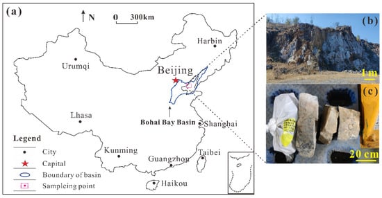
Figure 1.
Map showing the location of bohai bay basin in China. (a) Sampling location; (b) Outcrop of Majiagou formation; (c) Photographs of limestone samples.
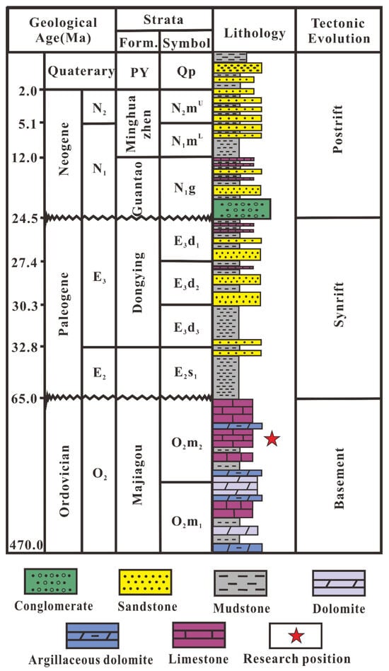
Figure 2.
Stratigraphic lithology of the Bohong Depression Region [16].
3. Experiments
3.1. Samples
Limestone samples were collected from the outcrop of the Upper Majiagou Formation of the Bohai Bay Basin, China (Figure 1b,c). Eight sets of standard cylindrical core plug (C1, C2, C3, C4, C5) were drilled with a diameter of 2.5 cm and a length of 5 cm. The limestone samples were also cut into cube shapes with different size, Cube–4 × 4 × 4 cm, Cube–4 × 4 × 2 cm, Cube–4 × 2 × 2 cm and Cube–2 × 2 × 2 cm. The remaining parts were crushed and sieved into two groups of cuttings: Powder-a (4.7–6.75 mm in diameter), and Powder−b (1–1.7 mm in diameter) (Figure 3). All samples were measured by 100% water saturation NMR. For five core samples, the pulse attenuation method was used to measure permeability. Moreover, the remaining parts of limestone samples were also taken for characterizing pores via SEM analyses following the Chinese standard SY/T 5162-2014 [17].
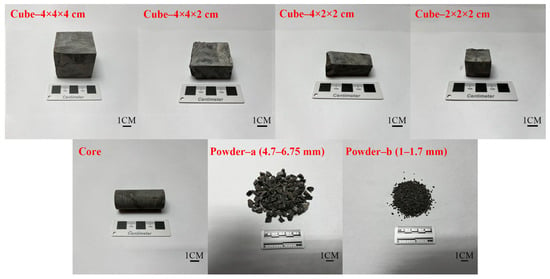
Figure 3.
Limestone samples of cores, cubic, and cuttings.
3.2. NMR and Centrifugal Experiments
The water-saturated NMR technique is based on the NMR relaxation behavior of spinning hydrogen nuclei (1H) in fluids contained in rocks in the presence of uniformly distributed static magnetic and radio frequency fields. The measured transverse relaxation time (T2) consists of three components [18]:
where T2S, T2D, and T2B are the surface relaxation time, diffusion relaxation time and bulk relaxation time, respectively. Diffusion relaxation is the self-diffusion of fluid molecules, which is formed by proton spin diffusion via a strong internal field gradient, and can be expressed by the equation [19]:
where D is the free diffusion constant for the relevant molecule, G is the magnetic field gradient, γ is the magnetogyric ratio, and TCP is the Carr–Purcell spacing (0.5 of the echo spacing). In a uniform magnetic field, there is no magnetic field gradient, and thus the diffusion relaxation time is not considered during the experiment. The bulk relaxation time depends on the properties of fluid (chemical composition, viscosity, etc.), which is much larger than T2S. Therefore, for 1H bearing fluids in porous media, T2 is mainly affected by surface relaxation, which is determined by pore size [19]. Thus, T2 is expressed as follows:
where is the surface relaxivity; S is the specific area of the pore; V is the volume of the pore; FS is the pore geometry morphologic factor, with Fs = 3 for spherical pores [20]; and rc is the diameter of the pores. Meanwhile, for the T2 spectra of a 100% saturated water sample, the NMR signal intensity can be converted to porosity using a standard calibration method [21]:
where Vp is water volume in 100% water-saturated sample in cm3, V is water volume in the standard sample in cm3, Mp is the total signal intensity of a 100% water-saturated sample, and M is the total signal intensity of the standard sample.
To analyze the porosity characteristics and to determine the T2 cutoff values (T2C) of the limestone samples, all samples at 100% water saturation (Sw) were set for NMR measurement. Four core samples (C1, C2, C3, C4) were then centrifuged using a CSC-10 Super Core Centrifuge to obtain an irreducible water condition with a 6000 RPM corresponding to centrifuge pressure of 143 psi [22], after which NMR measurements were performed again.
Notably, for water-saturated cuttings samples, some water is distributed in the intergranular spaces between individual cuttings, which may cause errors in porosity measurements. Therefore, water on the surface of the saturated sample cuttings was carefully removed by placing the saturated cuttings in a moist sponge and then pressing the sponge for a few seconds to remove intergranular water between the cuttings [6].
In this study, NMR analysis was performed using an Oxford GeoSpec 12/53 core analyzer with a uniform magnetic field of 12 MHz. All NMR measurements were performed at 30 °C. the parameters of CPMG pulse sequence were set as follows: echo spacing of 0.1 ms, echo numbers of 13,158, recycle delay of 300 ms, and scan number of 16.
3.3. Permeability Measurement
The evaluation of rock permeability involves both direct and indirect methods. For the five core samples (C1–C5), the absolute permeability (Kp) was obtained using pulse attenuation method by flowing air through the core sample until the pressure at both ends is equilibrated. For cubes and cuttings samples, it is difficult to measure permeability using the direct method. Therefore, the Coates and SDR empirical models, based on NMR-T2 spectra, are used [23,24].
For the Coates model, a relationship between porosity, irreducible water condition, and permeability is established as follows:
where is the porosity, %; C is a constant; and Sir is the irreducible water saturation, %:
where T2min is the minimum T2 relaxation time, ms, T2max is the maximum T2 relaxation time, ms; and A(T2i) is the signal amplitude corresponding to any relaxation time T2i. The T2C value varies for different types of carbonates, which is related to different types of pore space, pore structure, and mineral compositions [25]. Generally, T2C values are determined using the centrifugal method [26],
The SDR model takes pore size distribution into account to estimate permeability:
where is the nuclear magnetic porosity in %, C1 is a constant, and T2g is the geometric mean of the T2 distribution.
4. Results
4.1. NMR Spectra Result for Cubes and Cuttings
Figure 4 shows the NMR-T2 spectra for different sizes of samples at 100% water saturation. It is worth noting that the samples used in this experiment were of different masses, thus the T2 spectra of all samples were normalized. For five core samples, the NMR-T2 spectra show a single peak-like shape, overlapping well and centered at approximately 10 ms. According to Equation (2), T2 relaxation time was converted to pore diameter size. The surface relaxivity is 37.33 for limestone [27]. Moreover, pores are classified into micropore (<100 nm), mesopore (100–1000 nm), and macropores (>1000 nm) [28]. The results show that the limestone samples are dominated by mesopores and macropores, and the proportion of micropores is only about 10%. For cube samples, the NMR spectra were generally consistent with the core samples. However, for two groups of cuttings, the NMR spectra were shifted to the right (Figure 4b), which indicates that some changes have occurred in the pore-size characteristics of this cuttings sample [11].
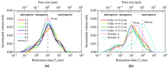
Figure 4.
T2 spectra of water-saturated limestone samples: (a) core samples, (b) cubic and cuttings samples.
4.2. NMR Results for Core Plugs at Sw and Sir
The NMR results of the cores under 100% water saturation (Sw) and irreducible water saturation (Sir) are shown in Figure 5. After the high-speed centrifugation experiment, the signal amplitude of the single peak of the sample decreases with the loss of the movable moisture. The decrease or disappearance of the signals provides information about the movable water in the limestone pores, and the remaining signals provides information on the irreducible water in the limestone pores [29]. For the four core samples C1, C2, C3, and C4, the Sirs were 95.72%, 93.60%, 94.06%, and 95.18%, respectively. This indicates that for tight carbonate rocks, the irreducible water content is high and difficult to displace. It can be inferred that a large amount of irreducible oil is difficult to extract due to low porosity and low permeability conditions for this limestone reservoir.
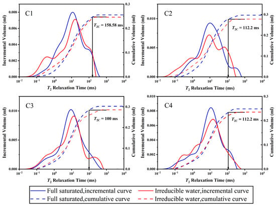
Figure 5.
T2 distributions of core samples at 100% water saturation and after centrifuging to 143 psi, showing the method to calculate a T2 cutoff value T2C.
The method of determining the T2C based on NMR centrifugal experiments is described by Yao et al. [26]. First, the NMR T2 distribution of core samples in 100% water saturation was transformed into a cumulative porosity curve (blue dashed line in Figure 5), and the NMR T2 distribution of cores under the optimal centrifugal force of 143 psi was transformed into a irreducible water cumulative porosity curve (red dashed line in Figure 5). Then, based on the maximum cumulative porosity value under irreducible water condition, a horizontal line parallel to the transverse T2 time was plotted to intersect the accumulation curve for 100% water saturation at one point. Finally, based on this intersection point, a line perpendicular to the transverse coordinate T2 time is plotted, and T2c is the intersection of this line with the transverse axis. In this study, the centrifugation-T2C for the selected sample cores ranged from 100 ms to 158.58 ms, which is consistent with the previous studies [25]. The average value of the T2C of the four samples was chosen as the T2C for this study, i.e., T2C = 120.75 ms.
4.3. Pore and Permeability Characterizations of Limestone Samples
The mineral composition of the limestone of the Ordovician Upper Majiagou Formation is mainly calcite and dolomite. As shown in the SEM microscopy results (Figure 6), intergranular pores, dissolution pores, intercrystalline pores, and microfractures are developed in the limestone.
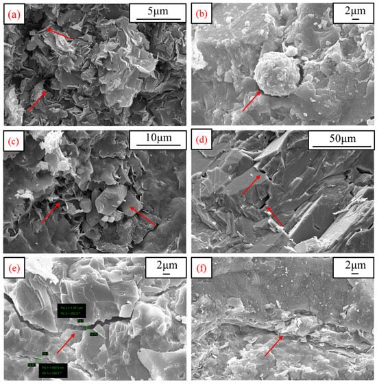
Figure 6.
SEM images of intergranular pores (a,b), dissolution pores (c), intercrystalline pores (d), microfractures (e,f).
Intergranular pores included the residual intergranular pores between the deposited particles and the intergranular dissolved pores formed by the residual intergranular pores further expanding outwardly. Most of the intergranular pores observed under the microscope were residual intergranular pores, some of which are filled with authigenic illite, which shows unevenly foliated grains with irregular grain boundaries under the microscope [30] (Figure 6a), and some of these intergranular pores are filled with pyrite, surrounded by calcite (Figure 6b). Under the microscope, the pyrite mainly appears framboidal and spherical [31] and the calcite crystals mainly appear rhombohedra [32]. Dissolved pores are secondary pores formed via the dissolution of fragmented particles. The dissolved pores in the study area are mainly calcite dissolved pores, and some of them are filled with autogenous quartz and silky illite (Figure 6c). Intercrystalline pores are micropores between matrix grains and between intercrystals such as authigenic clay minerals. Microscopically observed intercrystalline pores of calcite are usually triangular or polygonal in shape with smooth, straight edges (Figure 6d). The microfractures in the study area are mainly related to tectonic movement [33]. There are many stages of fractures in the study area; a large number of microfractures are unfilled (Figure 6e) and some are filled with silky illite (Figure 6f).
Moreover, Table 1 shows the results of the pulsed attenuation method for the core samples and the porosity obtained by NMR. The porosity of the five core samples ranges from 0.96% to 1.21%, with an average of 1.07%, and the permeability ranges from 0.00252 × 10⁻³ μm2 to 0.00502 × 10⁻³ μm2, with an average of 0.00379 × 10⁻³ μm2. Carbonate reservoirs with porosity less than 4% and permeability less than 1 × 10⁻³ μm2 are classified as extra-low porosity and extra-low permeability reservoirs in the China evaluation standard for physical properties of sedimentary reservoirs of SY/T 6285-2011. Compared with the experimental results, the Lower Paleozoic Ordovician carbonate reservoir is the extra-low porosity and extra-low permeability reservoirs.

Table 1.
The result of core samples.
Table 2 shows the results of the NMR porosity of the cubic and cutting samples. There was little difference in porosity between the samples of different sizes, but the Sir and T2g of the two sets of cutting samples was significantly different from that of the cubic and core samples. This is due to a change in the pore size of the cuttings sample [5], which is discussed in detail in Section 5.2.

Table 2.
Cubic and cutting samples test results.
5. Discussion
5.1. Effect of Rock Sample Size on Porosity
As shown in Figure 7, the porosity of the cube and cuttings is basically equal to the average porosity of the core; the relative error is between 1.87–16.82% and the average relative error is 7.63%. In this work, the relative standard deviation (RSD) was used to evaluate the differences between the porosity of samples with different sizes. For core samples of the same size, RSD = 9.60%. In comparison, the RSD of the four groups of cube samples of different sizes is 7.71%, the RSD of the two groups of cuttings samples is 6.73%, and the RSD of the cube and cuttings samples of different sizes is 7.74%, all of which are less than 9.60%, indicating that the porosity is independent of the sample shape and size. Therefore, for carbonate rocks, cubic samples and cuttings samples larger than 1 mm porosity can be used to represent reservoir porosity.
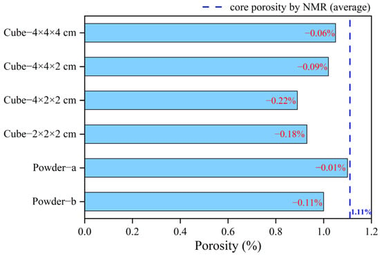
Figure 7.
Porosity of limestone samples with different sizes.
5.2. Effect of Rock Sample Size on PSD
According to the transformation method of T2 relaxation time to PSD and the classification of pores, the percentage of micropore, mesopore, and macropore of limestone samples were obtained (Figure 8). For five core samples, the average proportions of micropores, mesopores, and macropores are 9%, 38%, and 53%. For four cube samples, the proportions of the three types of pores are close, which are 12%, 34%, and 54%; For the two groups of cuttings samples, the pore proportions are quite different. For cuttings with particle size of 4.7–6.75 mm, the proportions of micropores, mesopores, and macropores are 6%, 25%, and 69%, respectively. For cuttings of 1–1.7 mm, the proportions are 4%, 10%, and 86%, respectively. The above results show that for core and cubic samples the proportion of the three types of pores is almost the same. Compared with the cuttings sample, the proportion of micropores and mesopores decreases while the proportion of macropores increases significantly as the particle size of cuttings decreases. This result is mainly related to the mechanical pulverization effect and to the interparticle void effect. The mechanical pulverization effect during the process of cutting and pulverizing samples can cause the proportion of macropore to increase and the proportion of micropore and mesopore to decrease. Arson and Pereira [34] showed that undamaged and damaged rocks have different PSD characteristics. Han et al. [35] showed that pulverization has a negligible effect on the 2 nm micropores and that the damage of the sample will form secondary pores and cracks, which are mainly macropores and mesopores. In this study, for cube samples, the mechanical pulverization effect was small and the vast majority of pores remained intact. Meanwhile, for cuttings samples, the mechanical pulverization effect was large and most of the pores were destroyed, causing some micropores or mesopores to open or form cracks. Moreover, SEM images of the samples show that most of the pores of the limestone samples are filled with minerals. During the crushing process, the discrete minerals filled in the pores are easily separated, resulting in an increased proportion of macropores. The remaining water in the interparticle void can also increase the NMR measurement of macropores. Smith and Schentrup [36] demonstrated that larger size particles contained larger interparticle pores. Lenormand and Fonta [6] suggested that for cuttings with smaller particle sizes, the amount of liquid trapped by capillarity between the cuttings is very large, and some methods can be used to reduce the influence of interparticle water. Although we performed pretreatments between NMR tests to eliminate the effect of interparticle voids, this interparticle space effect may still affect the results of macropore measurements.
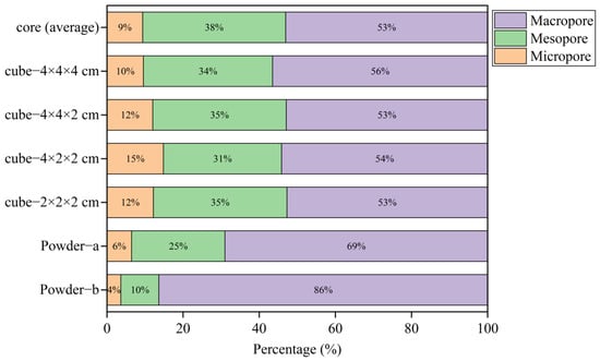
Figure 8.
Distribution of pore sizes of different sized chert samples.
5.3. Effect of Rock Sample Size on Permeability
For both the Coates and SDR models, the key is to obtain the constants C and C1 in Equations (4) and (6) from the experiment data. The constants C and C1 vary significantly for different rocks; for example, C in the Coates model for sandstone is generally 0.0001. For carbonate, the C1 in the SDR model is 0.1, according to Fleury et al. [37]. Moreover, according to Amabeoku et al. [38], for rocks with the same lithology, the constant C and C1 are selected differently in different regions. Therefore, in this study, the optimal constant C and C1 was obtained by mathematical fitting of the permeability Kp and NMR data of five cores. As shown in Figure 9a, the optimal value of the Coates model C is 0.7487, with R2 = 0.8655; in Figure 9b, the optimal value of the SDR model C1 is 0.00003, with R2 = 0.9146.
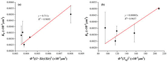
Figure 9.
Determination of the Coates model constant C (a) and the SDR model constant C1 (b).
Figure 10 shows the error between the Coates model and the SDR model and the measured permeability. The small error indicates that the two models can accurately predict the permeability of limestone samples. Permeability of cubic samples and cuttings samples is shown in Figure 11. For the four cubic samples, the prediction results of the Coates model and the SDR model are slightly different from the core permeability. For the two groups of cuttings, the prediction results of the two models are significantly different from the core results, with an error of one–two orders of magnitude; the smaller the particle size of the debris, the larger the error. This situation is highly similar to the change in PSD described above. And previous studies have suggested that the permeability is largely dependent on the grain size [39].
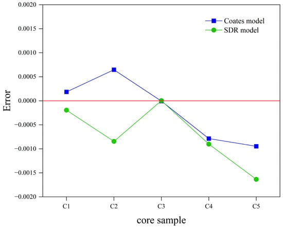
Figure 10.
The error between the model’s predicted value and the measured value.
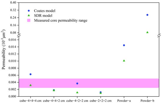
Figure 11.
Permeability results of cubic samples and cuttings samples.
At the same time, for these samples, the larger values of T2 in the cuttings (especially powder-b) imply much larger permeabilities than the other samples, which is consistent with the larger pore size. For powder b, the permeability of the Coates model is significantly higher than that of the SDR model. This is because the Coates model considers that the permeability mainly depends on the macropores with good connectivity in the sample and considers the effect of movable porosity on the permeability, while the SDR model introduces T2g, the contribution of pores of different sizes to permeability was averaged to reduce the effect of macropores on permeability. This reminds us that when using these two models for permeability prediction, the PSD characteristics and pores connectivity of the sample should be considered to improve the applicability of the model.
6. Applications
Cuttings analysis is a common practice in laboratory settings, and the selection of an appropriate cutting size to substitute intact cores is crucial in determining the petrophysical property of reservoir. The results of this study show that carbonate samples with >1 mm cutting can be used to obtain porosity; however, for PSD and permeability, the use of cuttings < 6.7 mm in diameter is not recommended.
Moreover, it is important to extrapolate the application of cuttings from the laboratory to the field. When the laboratory analysis is applied to the field, it must also consider the representative problems of the field cuttings, such as wellbore collapse, particle gravity differentiation, and drilling mud contamination. Due to gravitational particle divergence, the lag times calculation is used to identify which reservoir the cuttings are coming from. This method is often considered to be accurate in vertical Wells, with significant errors in horizontal and deviated Wells [12]. Some of the cuttings with particle sizes more than 5 mm may have resulted from the collapse of boreholes in unknown stratigraphic positions [10]. From a cuttings transport and dispersion point of view, cuttings with small particle size are easily contaminated by drilling mud [40]. Meanwhile, according to the results of this study, the cuttings permeability of 1–1.7 mm is much larger than standard core permeability. Thus, the use of cuttings with a particle size of less than 6.75 mm to represent the actual formation physical properties is not recommended.
7. Conclusions
The aim of this paper is to verify the feasibility of substituting intact cores with drilling cuttings in carbonate rocks and the effect of size on sample physical properties using low-field NMR techniques. The following conclusions are drawn from experimental results:
- (1)
- In laboratory analyses using NMR techniques, cuttings with a size of 1–1.7 mm can accurately measure porosity;
- (2)
- In laboratory analyses using NMR techniques, cuttings with a particle size of less than 6.75 mm do not accurately characterize the properties of extra-low porosity and extra-low permeability rocks, because of deviations in permeability and PSD;
- (3)
- For millimeter-sized limestone cuttings, PSD and permeability are severely affected by mechanical pulverization effect and interparticle water.
Author Contributions
Conceptualization Y.C.; methodology, S.W.; validation, S.W.; investigation, S.W. and Z.W.; writing—original draft preparation, S.W.; and writing—review and editing, X.S. All authors have read and agreed to the published version of the manuscript.
Funding
This work was supported by the National Natural Science Foundation of China [42125205; 42202195] and the Fundamental Research Funds for the Central Universities [2652023001; 2652023066].
Data Availability Statement
Data is contained within the article.
Conflicts of Interest
The authors declare no conflicts of interest.
References
- Roehl, P.O.; Choquette, P.W. Carbonate Petroleum Reservoirs; Springer Science & Business Media: Berlin/Heidelberg, Germany, 2012. [Google Scholar]
- Santarelli, F.J.; Marsala, A.F.; Brignoli, M.; Rossi, E.; Bona, N. Formation Evaluation From Logging on Cuttings. SPE Reserv. Eval. Eng. 1998, 1, 238–244. [Google Scholar] [CrossRef]
- Mirotchnik, K.; Kryuchkov, S.; Strack, K. A Novel Method To Determine Nmr Petrophysical Parameters From Drill Cuttings. In Proceedings of the SPWLA 45th Annual Logging Symposium, Noordwijk, The Netherlands, 6–9 June 2004. [Google Scholar]
- Yu, Y.; Menouar, H. An Experimental Method to Measure the Porosity from Cuttings: Evaluation and Error Analysis. In Proceedings of the SPE Production and Operations Symposium, Oklahoma City, OK, USA, 1–5 March 2015. [Google Scholar]
- Hübner, W. Studying the Pore Space of Cuttings by NMR and μCT. J. Appl. Geophys. 2014, 104, 97–105. [Google Scholar] [CrossRef]
- Lenormand, R.; Fonta, O. Advances in Measuring Porosity and Permeability from Drill Cuttings. In Proceedings of the SPE/EAGE Reservoir Characterization and Simulation Conference, Abu Dhabi, United Arab Emirates, 28–30 October 2007. [Google Scholar]
- Solano, N.A.; Clarkson, C.R.; Krause, F.F.; Lenormand, R.; Barclay, J.E.; Aguilera, R. Drill Cuttings and Characterization of Tight Gas Reservoirs—An Example from the Nikanassin Fm. in the Deep Basin of Alberta. In Proceedings of the SPE Canadian Unconventional Resources Conference, Calgary, AB, Canada, 30 October–1 November 2012. [Google Scholar]
- Ortega, C.; Aguilera, R. A Complete Petrophysical-Evaluation Method for Tight Formations From Drill Cuttings Only in the Absence of Well Logs. SPE J. 2013, 19, 636–647. [Google Scholar] [CrossRef]
- Fellah, K.; Utsuzawa, S.; Song, Y.Q.; Kausik, R. Porosity of Drill-Cuttings Using Multinuclear 19F and 1H NMR Measurements. Energy Fuels 2018, 32, 7467–7470. [Google Scholar] [CrossRef]
- Chang, Y.H.; Yao, Y.B.; Liu, Y.; Zheng, S.J. Can cuttings replace cores for porosity and pore size distribution analyses of coal? Int. J. Coal Geol. 2020, 227, 15. [Google Scholar] [CrossRef]
- Siddiqui, S.; Grader, A.S.; Touati, M.; Loermans, A.M.; Funk, J.J. Techniques for Extracting Reliable Density and Porosity Data From Cuttings. In Proceedings of the SPE Annual Technical Conference and Exhibition, Dallas, TX, USA, 9–12 October 2005. [Google Scholar]
- Egermann, P.; Doerler, N.; Fleury, M.; Behot, J.; Deflandre, F.; Lenormand, R. Petrophysical Measurements From Drill Cuttings: An Added Value for the Reservoir Characterization Process. SPE Reserv. Eval. Eng. 2006, 9, 302–307. [Google Scholar] [CrossRef]
- Munn, K.; Smith, D.M. A NMR Technique for the Analysis of Pore Structure-Numerical Inversion of Relaxation Measurements. J. Colloid Interface Sci. 1987, 119, 117–126. [Google Scholar] [CrossRef]
- Al-Mahrooqi, S.H.; Grattoni, C.A.; Moss, A.K.; Jing, X.D. An Investigation of the Effect of Wettability on NMR Characteristics of Sandstone Rock and Fluid Systems. J. Pet. Sci. Eng. 2003, 39, 389–398. [Google Scholar] [CrossRef]
- Hao, F.; Zhou, X.H.; Zhu, Y.M.; Zou, H.Y.; Yang, Y.Y. Charging of Oil Fields Surrounding the Shaleitian Uplift From Multiple Source Rock Intervals and Generative Kitchens, Bohai Bay Basin, China. Mar. Pet. Geol. 2010, 27, 1910–1926. [Google Scholar] [CrossRef]
- Ye, T.; Wei, A.J.; Gao, K.S.; Sun, Z.; Li, F. New Sequence Division Method of Shallow Platform with Natural Gamma Spectrometry Data: Implication for Reservoir Distribution—A Case Study From Majiagou Formation of Bozhong 21–22 Structure, Bohai Bay Basin. Carbonates Evaporites 2020, 35, 14. [Google Scholar] [CrossRef]
- SY/T 5162-2014; Analytical Method for Rock Sample by Scanning Electron Microscope. Petroleum Industry Press: Beijing, China, 2022.
- Sun, X.; Yao, Y.; Liu, D.; Ma, R.; Qiu, Y. Effects of Fracturing Fluids Imbibition on CBM Recovery: In Terms of Methane Desorption and Diffusion. SPE J. 2024, 29, 505–517. [Google Scholar] [CrossRef]
- Straley, C. In An Experimental Investigation of Methane in Rock Materials. In Proceedings of the SPWLA 38th Annual Logging Symposium, Houston, TX, USA, 15–18 June 1997. [Google Scholar]
- Zheng, S.J.; Yao, Y.B.; Liu, D.M.; Cai, Y.D.; Liu, Y. Characterizations of Full-scale Pore Size Distribution, Porosity and Permeability of Coals: A Novel Methodology by Nuclear Magnetic Resonance and Fractal Analysis Theory. Int. J. Coal Geol. 2018, 196, 148–158. [Google Scholar] [CrossRef]
- Wang, Z.F.; Yao, Y.B.; Ma, R.Y.; Zhang, X.A.; Zhang, G.B. Application of Multifractal Analysis Theory to Interpret T2 Cutoffs of NMR Logging Data: A Case Study of Coarse Clastic Rock Reservoirs in Southwestern Bozhong Sag, China. Fractal Fract. 2023, 7, 20. [Google Scholar] [CrossRef]
- Mai, A.; Kantzas, A. On the Characterization of Carbonate Reservoirs Using Low Field NMR Tools. In Proceedings of the SPE Gas Technology Symposium, Calgary, AB, Canada, 30 April–2 May 2002. [Google Scholar]
- Coates, G.R.; Xiao, L.; Prammer, M.G. NMR Logging: Principles and Interpretation; Halliburton Energy Services: Huston, TX, USA, 1999. [Google Scholar]
- Morriss, C.; Rossini, D.; Straley, C.; Tutunjian, P.; Vinegar, H. Core Analysis By Low-field Nmr. Log Anal. 1997, 38, 84–95. [Google Scholar]
- Westphal, H.; Surholt, I.; Kiesl, C.; Thern, H.F.; Kruspe, T. NMR Measurements in Carbonate Rocks: Problems and an Approach to a Solution. Pure Appl. Geophys. 2005, 162, 549–570. [Google Scholar] [CrossRef]
- Yao, Y.B.; Liu, D.M.; Che, Y.; Tang, D.Z.; Tang, S.H.; Huang, W.H. Petrophysical Characterization of Coals by Low-field Nuclear Magnetic Resonance (NMR). Fuel 2010, 89, 1371–1380. [Google Scholar] [CrossRef]
- Lawal, L.O.; Adebayo, A.R.; Mahmoud, M.; Dia, B.; Sultan, A.S. A Novel NMR Surface Relaxivity Measurements on Rock Cuttings for Conventional and Unconventional Reservoirs. Int. J. Coal Geol. 2020, 231, 16. [Google Scholar] [CrossRef]
- Wei, D.; Gao, Z.Q.; Zhang, C.; Fan, T.L.; Karubandika, G.M.; Meng, M.M. Pore Characteristics of the Carbonate Shoal from Fractal Perspective. J. Pet. Sci. Eng. 2019, 174, 1249–1260. [Google Scholar] [CrossRef]
- Kenyon, W.E. Petrophysical Principles of Applications of NMR Logging. Log Anal. 1997, 38, 21–43. [Google Scholar]
- Chen, T.; Wang, H.J.; Li, T.; Zheng, N. New insights into the formation of diagenetic illite from TEM studies. Am. Miner. 2013, 98, 879–887. [Google Scholar] [CrossRef]
- Wilkin, R.T.; Barnes, H.L.; Brantley, S.L. The size distribution of framboidal pyrite in modern sediments: An indicator of redox conditions. Geochim. Cosmochim. Acta 1996, 60, 3897–3912. [Google Scholar] [CrossRef]
- Palvanov, M.; Eren, M.; Kadir, S. EPMA analysis of a stalagmite from Küpeli Cave, southern Turkey: Implications on detrital sediments. Carbonates Evaporites 2024, 39, 11. [Google Scholar] [CrossRef]
- Zhao, F.Y.; Jiang, S.H.; Li, S.Z.; Zhang, H.X.; Wang, G.; Lei, J.P.; Gao, S. Cenozoic Tectonic Migration in the Bohai Bay Basin, East China. Geol. J. 2016, 51, 188–202. [Google Scholar] [CrossRef]
- Arson, C.; Pereira, J.M. Influence of Damage on Pore Size Distribution and Permeability of Rocks. Int. J. Numer. Anal. Methods Geomech. 2013, 37, 810–831. [Google Scholar] [CrossRef]
- Han, M.L.; Wei, X.L.; Zhang, J.C.; Liu, Y.; Tang, X.; Li, P.; Liu, Z.Y. Influence of Structural Damage on Evaluation of Microscopic Pore Structure in Marine Continental Transitional Shale of the Southern North China Basin: A Method Based on the Low-temperature N2 Adsorption Experiment. Pet. Sci. 2022, 19, 100–115. [Google Scholar] [CrossRef]
- Smith, D.M.; Schentrup, S. Mercury Porosimetry of Fine Particles—Particle Interaction and Compression Effects. Powder Technol. 1987, 49, 241–247. [Google Scholar] [CrossRef]
- Fleury, M.; Deflandre, F.; Godefroy, S. Validity of Permeability Prediction from NMR Measurements. Comptes Rendus Acad. Sci. Ser. II Chem. 2001, 4, 869–872. [Google Scholar] [CrossRef]
- Amabeoku, M.O.; Funk, J.J.; Al-Dossary, S.M.; Al-Ali, H.A. Calibration of Permeability Derived from NMR Logs in Carbonate Reservoirs. In Proceedings of the SPE Middle East Oil Show, Manama, Bahrain, 17–20 March 2001. [Google Scholar]
- Amaefule, J.O.; Altunbay, M.; Tiab, D.; Kersey, D.G.; Keelan, D.K. Enhanced Reservoir Description: Using Core and Log Data to Identify Hydraulic (Flow) Units and Predict Permeability in Uncored Intervals/Wells. In Proceedings of the SPE Annual Technical Conference and Exhibition, Houston, TX, USA, 3–6 October 1993. [Google Scholar]
- Georgi, D.T.; Harville, D.G.; Robertson, H.A. Advances In Cuttings Collection And Analysis. In Proceedings of the SPWLA 34th Annual Logging Symposium, Calgary, AB, Canada, 28–30 September 1993. [Google Scholar]
Disclaimer/Publisher’s Note: The statements, opinions and data contained in all publications are solely those of the individual author(s) and contributor(s) and not of MDPI and/or the editor(s). MDPI and/or the editor(s) disclaim responsibility for any injury to people or property resulting from any ideas, methods, instructions or products referred to in the content. |
© 2024 by the authors. Licensee MDPI, Basel, Switzerland. This article is an open access article distributed under the terms and conditions of the Creative Commons Attribution (CC BY) license (https://creativecommons.org/licenses/by/4.0/).