Abstract
As the depth of mines continues to increase, the problems of high temperature and potential heat damage become more prominent. In this study, the characteristics of natural and industrial heat sources in mines were reviewed, and then mainstream heat hazard governance technologies and corresponding utilization methods were discussed and compared. The first category of technologies comprises the optimization of ventilation systems, the insulation of roc heat, and artificial refrigeration. These cooling approaches are limited because the heat resources cannot be recovered. The second category is the utilization of waste industrial heat in mines, including the use of waste heat from the air compressors, drainage water, and foul airflow, but the current applications of these approaches have limited effectiveness in cooling the underground space. The third category is the application of geo-structures to recover natural heat in mines. Based on the principles of the chiller/heat pump cycle and the characteristics of heat sources and sinks in mines, the potential and constraints of each technology were discussed and summarized. This study provides a scientific reference for the selection of suitable heat governance and utilization technologies.
1. Introduction
Near-surface mining has been increasingly facing challenges in depleting resources, namely constrained by socio-environmental concerns and undesirable economic feasibility. The potential of extraction from deeper mineral bodies is becoming increasingly attractive to the mining industry. The depth to which a mine can be operated economically depends on the market value of the ore extracted therein [1]. Internationally, there is no strict definition of “deep mining” [2]. In China, mining operations deeper than 800 m are defined as deep mining. In the United States, deep mining is considered to be a mining activity conducted more than 5000 ft deep (1524 m) [3].
The consequent challenges associated with mining progressively deeper deposits include rock-pressure-related problems [4] and high-temperature-related hazards [5]. Because their working environments are in areas characterized by incremented ground temperatures, the problem of damage due to geothermal heat is more prominent in deep mines. At the same time, the heat sources in mines also include those from industry processes, such as equipment operation and blasting.
High temperatures in mines can seriously reduce production efficiency, obstructing sweating and disturbing the physical water and salt balance of the miners. Human operation accuracy significantly deteriorates as a result of long work hours in high-temperature environments, resulting in potential accidents. On the other hand, high-temperature and high-humidity environments, the heat dissipation efficiency of equipment drops, and the excessively high temperature tends to cause equipment insulation damage [6]. The commonly acceptable temperature limit for mining equipment operation is 40 °C, and that of flame-proof equipment is 45 °C [7]. When machines are operated near their temperature limit, the possibility of accidents increases significantly. Additionally, the Chinese standard “Safety Regulations for Metal and Non-Metallic Mines” (GB16423-2020) [8] stipulates that operation should be stopped immediately when the wet bulb temperature of the thermal environment of underground mines exceeds 30 °C [9].
China has set the goal of reaching its carbon peak by 2030 and carbon neutrality by 2060 [10]. Meanwhile, mining mineral resources from deep orebodies is also inevitable in the future. Therefore, efficient control and prevention of heat damage in mines, and the recovery of geothermal resources and industrial waste heat as a way to utilize green energy through advanced technological means can improve production efficiency [11] and reduce carbon emissions, supporting sustainable and green mining.
Previous studies have focused on heat transfer, the identification of heat hazard potential, individual cooling and heat utilization technologies, and the implementation of specific technologies. Comparisons and discussions of different technologies based on the fundamental principles and characteristics of the heat sources and sinks available in mines are still missing.
In this study, heat in mines classified as natural heat and industrial heat is first reviewed, including its sources and spatial and time distribution patterns. Then mainstream technologies in heat hazard governance, heat utilization, and geo-structure are presented. The technologies are presented in order from simple to complex. Based on the principles of the chiller/heat pump cycle, as well as heat sources and the available heat sinks in mines, the potential and difficulties of these technologies are discussed. This study provides a scientific reference for selecting appropriate heat governance and utilization technologies in engineering practices.
2. Heat Sources in Mines
2.1. Categorization of Heat Sources
The assessment and evaluation of heat sources in mines are fundamental to heat governance and utilization approaches. According to previous studies, the heat in mines can be mainly divided into natural heat as a result of increasing geothermal gradients and industrial waste heat [12,13]. In general, natural heat is extensive, massive, stable, and low in temperature; the amount of industrial waste heat is too small to moderate, with medium but fluctuating temperatures, and more often exists in working faces.
2.2. The Sources and Generation of Natural Heat
2.2.1. Auto-Compression of Air
The pressure of air flowing from the surface down through a mine shaft can be elevated due to compression by gravity; consequently, its temperature also increases, similar to the process in an air compressor. A part of the auto-compression heat can be absorbed by spray water.
2.2.2. Geothermal Heat Released from the Rock Strata
The geothermal gradient of the upper crust is generally between 15 and 40 °C/km [14]. The rock strata in deep mines are in a hotter zone of the upper crust compared with shallow mining; hence, the larger temperature difference between air and rock strata promotes heat flow from the rock to underground spaces.
2.2.3. Hot Groundwater
The temperature of groundwater is close to the rock mass where it is stored and transferred. The heat of groundwater is derived from the geothermal sources in surrounding rocks [15]. The hot groundwater might heat rock layers and then the heat is transferred to the ventilation air; the groundwater might also directly heat the ventilation air and increase air humidity through evaporation.
2.3. The Sources and Generation of Industrial Waste Heat
2.3.1. Heat Released by the Operation of Mining and Tunneling Machinery
Heat released from the operation of machinery is responsible for the largest portion of industrial waste heat in mines, and it can raise the mining face temperature by 5–10 °C [16]. The heat released by machinery operation usually is concentrated at the working faces, resulting in an obvious temperature increase in a small region around the working face in a short time. However, when the ambient temperature near the working face is higher than the surrounding rock, it cannot be easily absorbed by the geo-formation due to the low heat conductivity of the rock strata.
2.3.2. The Oxidization of Mineral Piles and Subsequent Heat Release
When the piled sulfate- or carbon minerals react with, the exothermic oxidization reaction releases heat into the environment and aggravates the heat hazard risks. If the heat released in the mineral piles is greater than that dissipated to the environment, the internal temperature of mineral piles is further increased, resulting in a risk of spontaneous combustion.
2.3.3. Heat Generation by Human Metabolism
Heat generation is a by-product of human metabolism, and it increases both the temperature and humidity of the air in working areas.
2.3.4. The Oxidation of Backfills with Cemented Tailing Backfill
A cemented tailing backfill is implemented in some non-coal mines. For example, when the glutted phosphogypsum is used as the backfilling material, the exothermic oxidization reaction aggravates the heat hazard risks, similar to the oxidation of piled minerals.
2.3.5. Blasting in Metal Mines
The blasting heat release is common in metal mines as the blasting mining method is often used. The heat generated by the explosion is released instantaneously and plays a leading role in the short-term increase in the stope air temperature [17,18].
2.4. Share of Different Heat Sources
Wagner [12] pointed out that, in deep-level mines, heat transfer from the rock mass accounts for more than 75% of total mine heat. However, heat generated from the operation of mining machinery is also significant in highly mechanized coal mines. Therefore, the share of heat sources is dynamic according to different locations and operation stages in mines.
From the spatial perspective, the share of natural heat released from surrounding rocks accounts for more in the air intake roadway, while industrial waste heat accounts for less. In the working faces, natural heat accounts for less, but the share of equipment operation, personnel metabolism heat, and other industrial waste heat is higher.
From the perspective of time, after the completion and commissioning, the waste heat generation is proportional to the operation duration and degree of mechanization, but the natural heat will not change.
The quality of industrial waste heat is higher than that of natural heat, especially the waste heat of air compressors, which can be directly used to heat water. Industrial waste heat can be used concentratedly, while natural heat is more dispersed and has a lower quality [19]. The heat sources in mines are summarized in Table 1.

Table 1.
Categories and characteristics of heat sources in mines.
3. Heat Hazard Governance Technologies
The optimization of ventilation systems and the insulation of heat sources benefit from their low cost, requirement of less retrofitting work, and available personnel and expertise. Currently, the most effective methods to control heat hazards in coal mines can be divided into four main categories [20]: the optimization layout of roadways and equipment locations, increasing ventilation capacity, the use of backfill mining methods, and spraying thermal insulation layers.
3.1. Optimization of Ventilation Systems
3.1.1. Optimizing the Layout of Roadways and Equipment Locations
The route of ventilation can be shortened by optimizing the development roadway, reducing the duration of heating the air and hence decreasing its temperature when the air arrives at the working faces.
Air in mines includes fresh airflow and return airflow. The route of fresh airflow should be kept away from points where the heat-dissipating equipment and mineral oxidation are located, and auxiliary equipment should be set along the return airflow route. In addition, downward ventilation is suggested, where the transportation tunnel is arranged in the return airflow route, preventing heat release during transportation from returning to working faces.
3.1.2. Increasing Ventilation Capacity
The airflow volume and speed can be improved by increasing the fan capacity to provide a better cooling effect.
3.1.3. Project Examples
By increasing the ventilation airflow by 13.3 m3/s at the Pinglang Coal Mine in Yunnan, China, the temperature on the working face dropped by 1 to 2 °C; at the Lilan Mine in Guangxi, China, an increase in the ventilation airflow by 53.33 m3/s resulted in a temperature decrease from 2 to 3 °C on the working face [21].
After implementing the “W” ventilation method at the 14233 ming face at the Dongtan Coal Mine, Shandong, China, the air temperature in the intake roadway decreased to 26.9 °C, which is 1–2 °C lower than in the case of using the “U” ventilation method [22].
3.2. Insulation of Rock Heat
3.2.1. Use of Backfill Mining Methods
The backfilling of mined-out areas is a fundamental component of many underground mining operations. The backfill material supports the surrounding rock mass, reduces wasteful dilution, enables a safe working area for production activities, and mitigates surface subsidence risk. In mines with heat hazard risks, using backfill mining methods can effectively insulate the heat dissipation from surrounding rocks by absorbing part of the heat. For example, the ultra-high water-based backfill material, whose main component is water, has a large specific heat capacity, providing a good heat prevention effect.
3.2.2. Spraying Thermal Insulation Layers
Spraying thermal insulation layers on surrounding rocks is easily conducted. However, its effectiveness is limited by its cost and technical maturity, so currently its application prospects are not extensive [23].
3.2.3. Project Examples
Li et al. [24] conducted industrial experiments by using glass microsphere mortar as the thermal insulation layer of a tunnel. The heat release in the tunnel was reduced by 64%, as the rock temperature was decreased from 34 °C to 30 °C.
3.3. Artificial Refrigeration Technology
When the temperature in mines reaches a certain level, the cooling effects by optimizing the ventilation system alone is reduced significantly, and artificial refrigeration should be applied. In this section, the principle of artificial refrigeration is first introduced, and then four representative artificial refrigeration technologies used in mines are presented: air compression refrigeration, two-stage water refrigeration, industrial ice refrigeration, and refrigeration by liquid–gas phase change.
3.3.1. Principles and Types of Chiller Cycles
Artificial refrigeration is achieved via a chiller cycle. The refrigeration machine that produces chilled water is referred to as a “chiller”. In general, a chiller cycle extracts heat from a heat source, such as a conditioned indoor space, to cool down its temperature, and then re-injects the heat into a heat sink, such as the outdoor ambient air. When applied in underground mines, the heat sources include the working faces, tunnels, chambers, etc., and the heat sinks can be ambient air or water bodies on the surface, ambient air underground, groundwater, underground water tanks, or even rock and soil bodies. Types of chiller cycles include vapor compression and sorption [25].
A vapor compression chiller cycle involves four components: a compressor, a condenser, an expansion valve/throttle valve, and an evaporator, as shown in Figure 1. In an evaporator, the refrigerant vaporizes by extracting heat carried by the chilled water returned from the heat source, thereby providing a cooling effect to the heat source. After exiting the evaporator, its pressure is raised by the compression process. The high-pressure refrigerant flows through a condenser/heat exchanger to reject heat before attaining the initial low pressure and returning to the evaporator. The vapor compression chiller cycles use reciprocating, screw, or centrifugal compressors to power the cycle. The compressors are most often driven by electric motors. The principle and structure of a heat pump described in Section 4 are essentially the same as those of the compression chiller cycle shown in Figure 1.
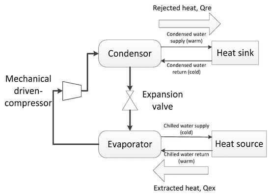
Figure 1.
The vapor chiller compression cycle. The cycle provides a cooling effect by exchanging the chilled water with the heat source (the object to cool).
Sorption chiller cycles, available as either absorption or adsorption designs, are driven by thermal energy produced from a direct-fired burner integrated with the chiller, or with thermal energy supplied indirectly to the chiller. As shown in Figure 2, the absorption cycle is similar to a compression cycle except the mechanical-driven compressor is replaced by a thermal compressor system consisting of an absorber, solution pump, and generator. Like a mechanical compressor, the thermal compressor takes low-pressure/low-temperature refrigerant from the evaporator where it extracts heat and delivers high-pressure/high-temperature refrigerant to the refrigerant condenser where it releases heat. Usually, the refrigerant/absorbent is a mixture of water (refrigerant) and lithium bromide (absorbent).
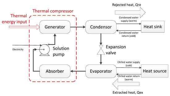
Figure 2.
The absorption chiller cycle. Instead of a mechanically driven compressor, a thermal compressor that consumes thermal energy is employed to drive the chiller cycle. The arrows indicate the flow direction of the refrigerant.
3.3.2. Air Compression Refrigeration
The principle of air compression refrigeration is similar to the aforementioned vapor compression chillers, but uses air as the refrigerant. The air does not vaporize and there is no condenser.
Turbo refrigeration is the most used air compression refrigeration technology, comprising a compressor, an expander, and a water heat exchanger. The air is compressed by the compressor to increase its pressure and temperature, and then its temperature decreases after exchanging heat with water in an integrated tank; afterward, it undergoes adiabatic expansion through the expander, lowering the pressure and temperature and providing cooling to the conditioned space.
Compared with the methods of industrial ice refrigeration and two-stage refrigeration, the heat capacity of the working medium is smaller, resulting in limited refrigeration capacity and a lower cooling coefficient. However, due to its small size, simple structure, and low cost, it can be manufactured as a mobile unit, meeting flexible and small-scale cooling demands, such as for individual working faces.
3.3.3. Two-Stage Water Refrigeration
This system uses water as the refrigerant and is divided into the surface section and the underground section. The process is shown in Figure 3.
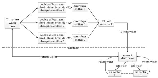
Figure 3.
Flow diagram of the two-stage water refrigeration. The returned warm water from the underground section is cooled by several units of centrifugal chillers and double-effect, steam-fired lithium bromide absorption chillers. The cold water is sent to the underground section and distributed to a series of air coolers in the mines to absorb heat.
The Surface Section
The surface section mainly consists of a return water tank, a cold water tank, a series of centrifugal chillers (a type of vapor compression cycle), and double-effect, steam-fired lithium bromide absorption chillers. Each of the absorption chillers is connected in a series with a centrifugal chiller to form a unit, and the units are connected in parallel.
The return water with a temperature of T1 enters the first-stage refrigeration system (the absorption chiller) and is cooled to T2, which is greater than 7 °C; otherwise, the thermal efficiency is low and the system may crystallize, affecting the refrigeration effect and operation of the system. The second stage of the system uses centrifugal chillers to further lower the temperature of the refrigerated water from T2 to T3 for use in underground air coolers.
The Underground Section
The underground cooling system mainly consists of multiple coolant distributors and air coolers. the cold water from the surface section is sent to the coolant distributors and then distributed to various air coolers. In the air cooler, the cold water cools down the ventilation air and the water temperature is increased from T3 to T1. The warmed water is then circulated to the surface as return water through a pump. The two-stage refrigeration scheme has significant advantages when applied in mines with prominent heat hazards, with the temperature decreasing by as much as 5 °C to 12 °C. However, due to the deformation of surrounding rocks in deep mines, the arrangement of air coolers becomes difficult. Besides, the cooling effect can be degraded due to the accumulation of coal dust and dirt on the air coolers over time. Regular cleaning is necessary, which also applies to ice refrigeration technology using air coolers. Additionally, a significant cooling loss can result from the large elevation gap and high static water pressure from the surface to the bottom of the mine, as well as the long and complex pipeline layout in deep mines. In such cases, it is necessary to install high- and low-pressure conversion devices, use well-insulated pipelines, and optimize the pipeline layout [26].
3.3.4. Industrial Ice Refrigeration (Figure 4)
Several industrial ice-making machines are installed on the ground, producing ice blocks that are then transported to the ice-melting pool underground through insulated pipelines. In the melting pool, the ice melts into cold water at around 0 °C. The cold water from the melting pool enters various air coolers, where it absorbs heat from the airflow, ultimately releasing cold air. Then, some of the water returns to the melting pool to melt the ice again, while the rest called residual return water is discharged into the bottom water tank. In the case that the residual return water is transported through an area with intensive operating equipment, it can also help cool this area to ensure the utilization of residual cooling capacity.
Essentially, the ice machine works based on the principle of compression chillers. The ice functions similarly to the chilled water between the chiller and conditioned space, but without returning to the chiller.
Industrial ice refrigeration and two-stage water refrigeration both belong to a scheme named ground centralization and underground cooling. Therefore, the heat dissipation and condensation heat from the ice-making and refrigeration system will not accumulate underground. Compared with the water refrigeration system, the ice refrigeration system is simpler and has a lower maintenance and operating cost.
Since latent heat is very large when ice melts, only 20% of the water demand in water refrigeration is required to achieve the same cooling capacity. Relying on this advantage of high cold energy density, industrial ice refrigeration technology is widely used in many deep mines. The main drawback of this technology is the transportation of ice blocks. Due to the acceleration and friction caused by gravity during the ice transportation from the surface to the underground, the pipeline requires greater strength. The ice transfer process can easily lead to pipeline breakage or blockage due to unreasonable pipeline layout. With technological advancements, the development and use of ice slurry transportation for cooling are expected to solve these problems [27].
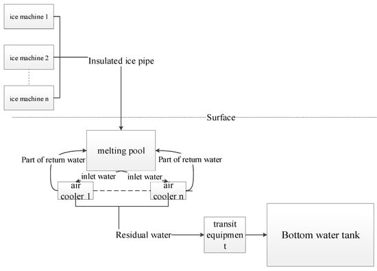
Figure 4.
Flow diagram of industry ice refrigeration. Ice produced on the surface is sent to the melting pool underground melting pool, where it melts into cold water at around 0 °C, and the cold water is used to cool the warm air from the air coolers. The cooled air ultimately cools down the temperature in mines.
3.3.5. Refrigeration by Liquid–Gas Phase Change (Figure 5)
As mentioned in the last paragraph, the latent heat associated with phase change is very large compared with sensible heat, and this is the foundation of many phase-change refrigeration processes. This technology utilizes the latent heat of vaporization to achieve the cooling effect. Some commonly used working fluids include liquid nitrogen, liquid carbon dioxide, and liquid oxygen. The liquid is distributed through the heat conduction pipeline, where it vaporizes by absorbing a large amount of heat from the surrounding environment. A gas parameter detector and auto-control system are installed in the pipeline outlet to ensure that the temperature and pressure are in a reasonable state at all times. When the temperature is too low, the valve on the right side is closed to prevent loss of refrigeration capacity.
The liquefied gas is easy to produce and has a large refrigeration capacity, and the system structure is simple. The disadvantage is that the vaporized refrigerant is directly discharged into the underground environment and cannot be recycled. Moreover, if carbon dioxide is used as a refrigerant, over-discharge to the working face environment can cause breathing difficulties for the workers and easily lead to safety accidents. Compared to the two-stage water and industrial ice refrigeration schemes, there are safety hazard concerns due to the transportation of liquefied gas from the surface instead of water [28,29].
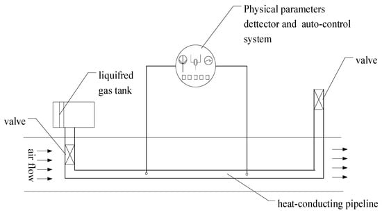
Figure 5.
Flow diagram of refrigeration by liquid–gas phase change. The distributed liquid coolant vaporizes in the heat-conducting pipeline by absorbing heat from the airflow, cooling down the temperature of the airflow.
3.3.6. Project Examples
A mobile air compression refrigeration system was employed in the Dahongshan Copper Mine, Yunnan, China to cool the high-temperature working face. The site monitoring data showed that the mobile refrigeration system could reduce the wet bulb temperature of the working face at the test site to below 30 °C. The overall temperature drop was 3.68 °C, and the cooling rate was 1.84 °C per hour [9].
The Morro Velho gold mine in Brazil was one of the first in the world to utilize artificial water refrigeration technology in mines. The initial surrounding rock temperatures reached 50 °C. A refrigeration system with a cooling capacity of up to 1744 kW and an airflow rate of 2300 m3/min was installed, capable of cooling air temperature from 30 °C to 6 °C.
The initial surrounding rock temperatures reached 44 °C at the Radbod coal mine in Germany. A refrigeration system with a cooling capacity of 581 kW was implemented and reduced the fresh air temperature at the working face from 22.5 °C to 19.5 °C [30].
The Pingmei Coal Mine, Henan, China has used an ice refrigeration system since 2006. Recorded temperature data show that the system has effectively reduced the temperature at the working face by 4.3 to 6.3 °C. Similarly, at the Quandian Coal Mine, with the implementation of an ice refrigeration system, the highest temperature at the mining face decreased by 7 to 8 °C, and the highest temperature at the tunneling face decreased by 8.8 °C [31].
Besides, an industrial experiment for a CO2 liquid–gas phase change refrigeration system was conducted at the Banshi Coal Mine, China, 2017. The test results showed that the system effectively decreased the ambient temperature at the tunneling face by 6.9 °C [32].
4. Waste Heat Utilization Technologies
The major sources of industrial waste heat in mines include air compressors, drainage water, and foul airflow, corresponding to which there are three major waste heat utilization approaches.
The first approach involves recovering the heat contained in the coolant of air compressors for various usage purposes [32]. The second approach is the extraction of the heat from drainage water using a water source heat pump to heat domestic water or for anti-freezing in wellbores [33]. The third approach is recovering the heat from the foul airflow through a contact or indirect spray-type heat exchanger using water as the heat carrier, and then heat in the water is further extracted by a heat pump. The specific technical principles, advantages, and disadvantages of these three technologies are discussed as follows.
4.1. Waste Heat Recovery from Air Compressor
During the operation of the air compressor, a large amount of heat is generated. The dissipated low-grade waste heat occupies 80–90% of the input power [34]. The cooling oil absorbs the excess heat from the air compressor, and when its temperature reaches the set threshold, the cooling oil valve opens, allowing the high-temperature cooling oil to enter a heat exchanger to transfer the heat to a water loop. Then, the cold cooling oil returns to the compressor to continue absorbing heat, and the valve closes. This cycle repeats to ultimately heat the water to a certain temperature sufficient for direct use on the surface. The main advantage of this technology is that it can use the cooling oil to dissipate heat from the compressor, thereby reducing energy waste and achieving waste heat utilization. Another advantage of this method is that it can supply stable heat as long as the air compressor is in operation. However, since this approach only extracts heat dissipated from specific equipment, its cooling effect is limited in the view of heat hazard governance.
A secondary heat exchange loop can be installed according to actual demands. For example, when it is used for producing water for bathing, which does not require very high temperatures [35], the primary water is heated to around 70 °C by the cooling oil, and then, in the secondary heat exchange loop, the temperature of the bathing water is increased to 45–50 °C by the primary circulating water [36]. It is necessary to consider the ratio of the water quantity for primary and secondary heat exchange, as well as whether the air compressor can obtain a normal cooling degree during operation [37].
The costs of this waste heat recovery system mainly derive from the installation and power consumption of the water pump to lift the cooling water to the surface, without considering the energy consumption of the air compressor itself as part of the waste heat recovery cost, since the air compressor always generates waste heat during operation. Moreover, the waste heat recovery system is independent of the air compressor, so the recovery system will not affect the normal use of the air compressor.
In some areas, the calcium and magnesium ion content in the water is high. Prolonged operation of an air compressor will cause scaling in the cooling system, affecting its heat transfer and heat utilization efficiency. Regular manual inspection and cleaning to remove scaling is necessary [38].
4.2. Waste Heat Recovery from Mine Drainage Water
The temperature of drainage water is constant throughout the year and contains a large amount of low-grade thermal energy, which can be extracted for surface use by a water source heat pump. A heat pump is a device that transfers heat from a low-temperature source (low-grade energy) to a high-temperature environment using mechanical energy. The structure of a heat pump is essentially the same as the compression chiller cycle depicted in Figure 1, including a compressor, a condenser, an expansion valve, and an evaporator. The principle is that the liquid refrigerant in the evaporator absorbs heat from drainage water (heat source) to vaporize, and then, the vapor is compressed to increase its pressure and corresponding saturation temperature. In the condenser, the vapor condenses to liquid, and the released latent heat warms up the water for utilization (heat sink). The liquid refrigerant is then sent to the evaporator to continue the cycle.
This method has the advantage of being able to extract a large amount of low-grade energy from mine drainage water. The disadvantage is that the corrosive substances in the mine water may corrode the devices and pipes, so it is necessary to treat the water or select appropriate thermal conductivity and corrosion-resistant materials for the interiors of the heat exchangers and pipes.
To recover the maximum amount of waste and to be proximally closer to the users, the water source heat pump usually is installed at the surface outlet of drainage water, and so barely provides a cooling effect to the underground space from the perspective of heat hazard governance.
4.3. Heat Recovery from Foul Airflow
4.3.1. Technology Schemes and Types
There are currently three types of technologies to recover heat from foul airflow: heat recovery via liquid spraying, shallow enthalpy heat recovery via direct vaporization, and deep enthalpy heat recovery via direct cooling [39]. These technologies are designed for different local environments and technical requirements, but their basic principles are the same, as the low-grade heat is transferred from the foul airflow to a water loop and further extracted for surface use through a water source heat pump. The main advantage is the stable heat recovery rate due to the stable temperature of the foul airflow. Additionally, it can reduce the dust and corrosive problems of mine ventilation air [40].
To maximize the heat extraction rate from the foul airflow, the system is supposed to be installed at the ventilation outlet of the foul air on the surface, so it barely provides any cooling effect for the underground space from the perspective of heat hazard governance. Besides, the resistance to airflow created by the installation of the heat exchanger at the outlet of foul air and the consequent impact on the ventilation effect should be evaluated.
4.3.2. Heat Recovery by Liquid Spray (Figure 6)
This technology consists of a heat pump cycle, a heat exchange diffusion tower, a collect pool, and a water treatment unit. The low-temperature and high-pressure atomized water droplets from the heat pump unit are sprayed in the heat exchange diffusion tower to absorb heat in the foul airflow [41]. The heated water droplets drop freely into the collect pool, from where they are sent to the water treatment process. The treated warm water is sent into the heat pump unit to extract the contained heat [42]. The principle of a heat pump is described in Section 4.2.
The system structure is complex, with a low heat recovery efficiency and a high energy consumption. In cold regions, it might lead to problems such as pipe freezing and poor continuity of heat supply.
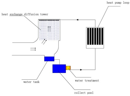
Figure 6.
Schematic diagram of heat recovery via liquid spraying. Arrows in the diffusion tower indicate the foul airflow, and other arrows indicate the direction of water loop extracting heat from the foul airflow.
4.3.3. Shallow Enthalpy Heat Recovery via Direct Vaporization (Figure 7)
Shallow enthalpy heat recovery via direct vaporization involves a foul air diffusion tower, a water supply tank, and a heat pump unit. The foul air heat exchanger is installed in the foul air diffusion tower and functions as the evaporator of the heat pump loop. The refrigerant of the heat pump absorbs heat from the foul air to evaporate. The heat absorbed by the refrigerant is extracted by the heat pump loop and then used to warm up the water for surface use.
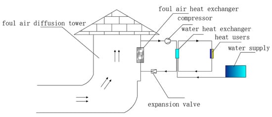
Figure 7.
Schematic diagram of shallow enthalpy heat recovery via direct vaporization.
4.3.4. Deep Enthalpy Heat Recovery via Direct Cooling (Figure 8)
Deep enthalpy heat recovery via direct cooling is essentially an improvement of the abovementioned method. Specifically, an antifreeze fluid heat extraction loop is added to first recover heat from the foul air and then pass the heat to the water loop, forming a two-stage heat extraction. The water loop and antifreeze loop are separated and independent of each other.
Since the freezing point of the antifreeze fluid is lower, the temperature of the cooled foul air flow can reach −15 °C. The enlarged enthalpy drop of the foul airflow results in a larger amount of heat recovered from the foul airflow compared with the shallow enthalpy heat recovery process [43], so this technology is named deep enthalpy heat recovery.
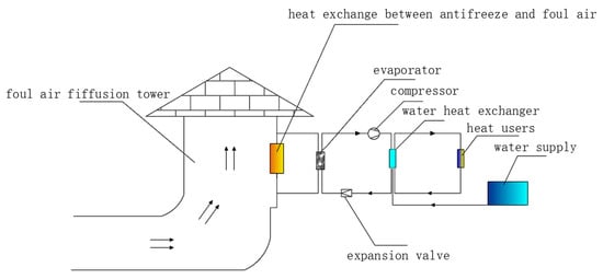
Figure 8.
Schematic diagram of deep enthalpy heat recovery via direct cooling.
4.4. Project Examples
A waste heat recovery and utilization system is was installed at the Liangshuijing coal mine, Shaanxi, CinaChina, to recover the waste in return airflow, burst water, and air compressors, in order to replace a conventional coal-fired boiler for district heating on the surface. The heating capacity is 35 ton tons of steam per hour. The temperature of foul air in winter ranges from 10–15 °C, and the temperature of drainage water in winter is between 13–17 °C [44].
The life cycle analysis showed that, although the capital investment of the waste heat recovery system was 12% higher than that of the boiler, the average annual life cycle cost of the waste heat recovery system was 13% less than the boiler [45].
In Zhangji Coal Mine, Anshui, China, a waste heat recovery system was implemented to utilize the heat contained in foul airflow and dissipated from compressors for the purpose of borehole anti-freeze, building heating, and bathing on the surface. The total heating load was 2568 kW in the winter and 160 kW in other seasons. The total annual cost was reduced by 54% compared with a coal-fired boiler and the annual CO2 emission was reduced by 3940 tons [46].
5. Application of Geo-Structures in Mines
A portion of the heat hazard in mines can be transformed into recoverable geothermal energy through certain technical means, meeting the energy demand in mining and staff use. The geo-structure is a new technology that combines ground source heat pumps with underground structures. Because some underground structures are installed in geoformations of constant temperature for a long time, they are combined with heat exchange pipes to function as underground heat exchangers, transferring the geothermal energy to surface users [47]. Some common geo-structures include energy tunnels, energy piles, and underground energy continuous walls. In a thermodynamic sense, these geo-structures can be regarded as ground source heat pumps that utilize geoformation as a heat source, and they have potential for utilization in heat hazard governance.
5.1. Energy Tunnels
An energy tunnel (Figure 9) absorbs the heat of surrounding rocks and air inside the tunnel by embedding the heat exchange pipes in the internal structure of the tunnel, supplying heating for ground buildings and serving both as a heat exchanger and a structural component. As the temperature in the high-temperature source (the tunnels) usually is higher than that of the surface air, it is more energy-efficient and environmentally friendly than traditional air source heat pumps, saving more than 30% of the energy.
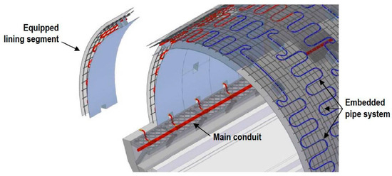
Figure 9.
A tunnel segmental lining serving as a ground heat exchanger [48].
In mines, tunnels where equipment is operated or those with a heat-intensive environment serve as potential geothermal resources, such as transportation tunnels, return air tunnels, and equipment chambers. Additionally, if these tunnels are in medium or deep in depth, the thermal energy in surrounding rocks is sufficient and of higher quality than that in shallow depth. The extraction and utilization of the heat reduces the underground temperature, mitigating heat hazard risks.
5.2. Energy Piles
Energy piles (Figure 10) are a type of pile structure with heat exchange pipes (usually U-bend tubes) set inside. They not only bear the load of the piles but also provide heat exchange capacity. There are different types of energy piles based on structure, such as steel pipe piles and reinforced concrete piles. Heat is extracted through the heat exchange pipes inside the piles and then utilized by a heat pump loop on the surface.
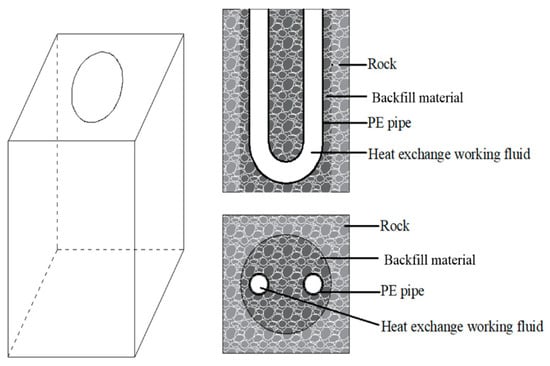
Figure 10.
Schematic diagram of energy piles [49].
In the current deep metal ore mining process, some horizontal or gently inclined ore bodies use room and pillar mining methods, and the mining pillars are generally not recovered at the end but left for support purposes. It is possible to consider using energy piles instead of mining pillars, which not only utilize geothermal energy but also increase the recovery rate by recovering the mining pillars. Additionally, U-bend heat exchange pipes can be combined with tunnel support structures to form energy anchor rods. However, it is necessary to consider that the deformation of surrounding rocks might lead to the deformation and cracking of pipes, further resulting in subsequent leakage and failure of the heat exchange medium.
5.3. Underground Energy Continuous Wall
The underground continuous energy wall binds heat exchange pipes to the reinforced structure of the underground continuous wall for extracting ground heat. In mines, it can be combined with structures such as explosion-proof enclosures, wind barriers, cut-off walls, and other structures [50].
The three abovementioned methods are all improvements of matured ground source heat pump technology with variant layouts of ground heat exchangers. They have the advantage of providing energy and mitigating mine heat hazards to a certain extent. Even by the end of a mine’s service life and after the termination of mining, it can continue to supply green energy for surface use as a way to re-use abandoned mines.
6. Discussion
The heat generated by natural sources in mines is extensive, long-range, low-grade, and stable. On the other hand, the waste heat from industrial work, especially that from the operation of machinery and blasting, tends to be temporary, higher in temperature, and concentrated around the working faces. Although the share of industry-derived heat in the total heat in mines is less than that of the natural heat, it more often causes heat damage to equipment and jeopardizes the health of miners. When the optimization of ventilation systems and the insulation of rock heat cannot provide effective cooling, local cooling at the working faces usually becomes the priority option.
Various artificial refrigeration and heat utilization technologies are presented in Section 3.3 and Section 4, as summarized in Table 2. Except for the phase change refrigeration and direct use, most of these technologies, as well as geo-structures, are based on the principle of a chiller cycle or heat pump.

Table 2.
Summary of artificial refrigeration and heat utilization technologies.
As described in Section 3.3.1, a chiller cycle or a heat pump essentially transfers heat from a heat source to a heat sink. One should keep in mind that when chiller cycles or heat pumps are applied to underground mines, the heat source, heat sink, and chiller unit might be located apart from each other a long distance.
As demonstrated in Figure 11, heat sources on the surface are more concentrated and have a higher heat flux. Among the heat sources underground, industry heat is more dispersed and the natural heat is of low grade but large amount. Heat sinks on the surface have a higher accommodation capacity and are proximally closer to users. However, the temperature of vent air underground is higher, deteriorating the cooling efficiency; the capacity of the water tank is limited especially for those integrated with a mobile refrigeration system; and the availability of sufficient groundwater flow is not guaranteed. To conclude, the most needed cooling objective is the working face underground, whereas heat sinks on the surface are the preferred candidates compared to heat sinks underground. No matter whether the chiller unit is located underground or on the surface, the separation of heat sources and sinks would result in long and complex transport of heat carriers or condensed water and high associated costs.
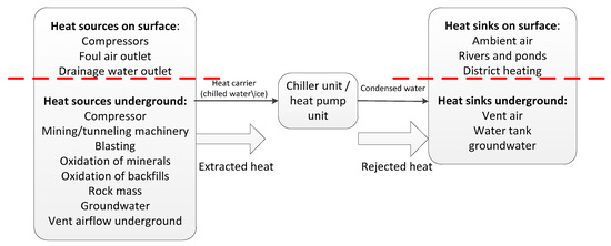
Figure 11.
Distribution of heat sources and sinks in mines.
The use of industrial waste heat in mines, including those from air compressors, drainage water, and foul airflow, has been commercially applied. However, in order to extract the maximum amount of waste heat, most heat recovery systems are installed at the foul air outlet or drainage water outlet on the surface, providing very limited or nearly no cooling effect to underground spaces.
Geo-structures are green energy technologies, which are currently not commonly used in deep mines. Compared with currently available methods, they have the potential to achieve purposes both in heat governance and utilization simultaneously. The capital investment for this technology is relatively large. Even after the mine is closed, it can still stably provide thermal energy and continue to create economic benefits.
7. Conclusions
The heat sources in mines are mainly divided into natural heat sources and industrial heat. Currently, mature technologies in mine heat hazard governance include the optimization of ventilation systems and artificial refrigeration measures, which have been proven to be effective in practice in different situations. However, as mining depth and temperatures increase, these governance technologies are limited by their effect, cost, and energy consumption, not only wasting significant geothermal energy existing in mines but also increasing carbon emissions.
Current heat utilization processes in mines aim to extract heat at the surface outlets of foul air and drainage water, or compressors, providing very limited cooling effect to the underground space. Technological advancements in geo-structures, such as energy tunnels in subway metro stations and energy piles in underground structures, are expected to be applied in the future in medium and deep mines to recover stable and massive natural heat mines.
Except for the phase change refrigeration and direct use, most heat governance and recovery technologies, as well as the geo-structures, are essentially chiller cycles or heat pumps. However, the separation of underground heat sources and potential heat sinks on the surface raises the challenges of a complex system structure, long-distance transfer of heat carriers, and high cost.
Author Contributions
Conceptualization, Y.R. and J.P.; methodology, J.P. and X.T.; formal analysis, D.L. and J.Z.; investigation, X.T. and P.P.; resources, Y.R.; writing—original draft preparation, X.T. and J.Z.; writing—review and editing, J.P., D.L. and P.P.; supervision, P.P.; project administration, Y.R.; funding acquisition, Y.R. All authors have read and agreed to the published version of the manuscript.
Funding
This research was funded by the Science and Technology Research Program of the Bureau of Geology and Mineral Exploration and Development Guizhou Province, China, Grant Number 2021[14], and the Science and Technology Support Program of Guizhou Province, China, Grant Number [2022]232. And The APC was funded by the Science and Technology Research Program of the Bureau of Geology and Mineral Exploration and Development Guizhou Province, China, Grant Number 2021[14].
Data Availability Statement
All data, models, and code generated or used during the study appear in the article.
Conflicts of Interest
Authors Yujin Ran, Jia Peng, Xiaolin Tian and Dengyun Luo were employed by the company Guizhou Shallow Geothermal Energy Development Co., Ltd. The remaining authors declare that the research was conducted in the absence of any commercial or financial relationships that could be construed as a potential conflict of interest.
References
- Fairhurst, C. Some Challenge of Deep Mine. Engineering 2017, 3, 527–537. [Google Scholar] [CrossRef]
- Ghorbani, Y.; Nwaila, G.; Zhang, S.; Bourdeau, J.; Cánovas, M.; Arzua, J.; Nikadat, N. Moving towards deep underground mineral resources: Drivers. challenges and potential solutions. Resour. Policy 2023, 80, 103222. [Google Scholar] [CrossRef]
- Wu, A.; Xu, K. The ECPH Encyclopedia of Mining and Metallurgy; Springer: Berling, Germany, 2022; pp. 1–3. [Google Scholar]
- Wagner, H. Deep Mining: A Rock Engineering Challenge. Rock Mech. Rock Eng. 2019, 52, 1417–1446. [Google Scholar] [CrossRef]
- Xu, Y.; Li, Z.; Chen, Y.; Jia, M.; Zhang, M.; Li, R. Synergetic mining of geothermal energy in deep mines: An innovative method for heat hazard control. Appl. Therm. Eng. 2022, 210, 118398. [Google Scholar] [CrossRef]
- Song, H.; Cheng, Z. Heat Injury Analysis and Prevention of a Large Deep Well Sulfur Mine. Nonferr. Met. Sci. Eng. 2011, 2, 74. [Google Scholar]
- MT/T 661-2011; Generaltechnical Condition for Electrical Apparatus Used Underground Mine. Standardization Administration of the People’s Republic of China: Beijing, China, 2011.
- GB16423-2020; Safety Regulation for Metal and Nonmetal Mines. Standardization Administration of the People’s Republic of China: Beijing, China, 2020.
- Li, J.; Yu, X.; Huang, C.; Zhou, K. Research on the Mobile Refrigeration System at a High Temperature Working Face of an Underground Mine. Energies 2022, 15, 4035. [Google Scholar] [CrossRef]
- Yu, B.; Zhao, Z.; Wei, Y.; Liu, L.; Zhao, Q.; Xu, S.; Kang, J.; Liao, H. Approaching national climate targets in China considering the challenge of regional inequality. Nat. Commun. 2023, 14, 8342. [Google Scholar] [CrossRef]
- Li, Z.; Wang, J.; Wang, J. Application of Heat Pipe Technology in the Waste Heat Recovery of Return Air in Coal Mine. Energy Energy Conserv. 2014, 44, 40–42. [Google Scholar]
- Wagner, H. The management of heat flow in deep mines. Geomechanik Tunnelbau 2013, 4, 157–163. [Google Scholar] [CrossRef]
- Zhu, S.; Wu, S.; Cheng, J.; Li, S.; Li, M. An Underground Air-Route Temperature Prediction Model for Ultra-Deep Coal Mines. Minerals 2015, 5, 527–545. [Google Scholar] [CrossRef]
- Payne, T.; Mitra, R. A review of heat issues in underground metalliferous mines. In Proceedings of the 12th U.S./North American Mine Ventilation Symposium, University of Nevada, Reno, NV, USA, 9–12 June 2008. [Google Scholar]
- Hartman, H.L.; Mutmansky, J.M.; Ramani, R.V.; Wang, Y. Mine Ventilation and Air Conditioning; Wiley-Interscience: Hoboken, NJ, USA, 1997. [Google Scholar]
- Roy, S.; Mishra, P.D.; Bhattacharjee, M.R.; Agrawal, H. Heat Stress in Underground Mines and its Control Measures: A Systematic Literature Review and Retrospective Analysis.Mining. Metall. Explor. 2022, 39, 357–383. [Google Scholar] [CrossRef]
- Wang, C.; Zhou, J.; Jian, J.; Zheng, X.; Luo, W. Ventilation refrigeration and cooling technology of high temperature heat damaged mine. Saf. Coal Mines 2022, 53, 245. [Google Scholar]
- You, S.; Sun, J.; Ji, H.; Feng, Q. Analysis of Thermal Environment and Its Influencing Factors in Deep Stope of Metal Mine. Geofluids 2022, 2022, 6408714. [Google Scholar] [CrossRef]
- Yuan, W. Heat-harm and Prevention Measures of Duddar Lead-zinc Mine. World Nonferr. Met. 2017, 32, 259. [Google Scholar]
- Jia, W.; Ji, J.; Zhang, M.; Zhang, X.; Cheng, H.; Dong, H. Research and engineering application of high temperature and thermal damage Prevention in deep mines. Coal Technol. 2020, 39, 89–90. [Google Scholar]
- Wang, D. Mine Ventilation and Safety; China University of Mining and Technology Press: Xuzhou, China, 2007. [Google Scholar]
- Wang, H. Analyze of Mines’ Thermodynamics and Determination of Ventilation Limit Depth of Dongtan Mine. Master’s Thesis, Shandong University of Science and Technology, Qingdao, China, 2006. [Google Scholar]
- Qiu, T.; Liu, J.; Huang, B. Design Study on Local Cooling System of Mine. Mine Constr. Technol. 2018, 39, 22–23. [Google Scholar]
- Li, G.; Xia, Y.; Li, Z. Research and application of insulating and cooling technology in deep mine roadway. Met. Mine 2010, 9, 152–154. [Google Scholar]
- Absorption Chillers for CHP Systems. Available online: https://www.energy.gov/eere/amo/articles/absorption-chillers-chp-systems-doe-chp-technology-fact-sheet-series-fact-sheet (accessed on 20 February 2024).
- Cheng, M.; Mine, D.C. Treatment Technology for Heat Damage in Deep Mine. Saf. Coal Mines 2017, 48, 132. [Google Scholar]
- Ji, J.; Zhang, M.; Jia, W.; Zhang, X. Research on Centralized Cooling System in Xiaoyun Coal Mine. Saf. Coal Mines 2019, 50, 98. [Google Scholar]
- Liu, J.; Zhou, S.; University, H.P. The Present Situation and Existing Problems of Artificial Refrigeration Cooling Technology of Coal Mine in China. J. Zhongyuan Univ. Technol. 2016, 27, 67–68. [Google Scholar]
- Liu, J.; Li, G.; Chang, D.; Li, Y. Present Situation and Prospect of Mine Geothermal Hazard Control Technology. Met. Mine 2021, 7. [Google Scholar]
- Yang, D.; Yang, T. Thermal Enviroment in Mine and Its Control; Metallurgical Industry Press: Beijing, China, 2009. [Google Scholar]
- Cui, Z.; Feng, Y.; Cao, P. Application of concentrated ice-making cooling technology by mechanical compression in coal mine. Colliery Mech. Electr. Technol. 2012, 4, 117–119. [Google Scholar]
- Song, D.P.; Zhou, X.H.; Li, J.Y.; Bai, G. Liquid carbon dioxide phase-change refrigeration and cooling technology of high temperature mine. Coal Sci. Technol. 2017, 45, 82–87. [Google Scholar]
- Zhang, L. Study on application and practice of comprehensive utilization technology of waste heat resources in coal mine. Coal Process. Compr. Util. 2021, 39, 84–86. [Google Scholar]
- Zhang, H.; Zhou, X.; Jiang, H.; Fang, S.; Zhi, X.; Qiu, L.; Wang, K. Performance limit of gas compression processes enhanced by self-utilization of compression waste heat. Energy Convers. Manag. 2022, 273, 116414. [Google Scholar] [CrossRef]
- Jia, J. Application of Ventilation Air Methane Oxidization and Waste Heat Utilization Technology in Shanxi Lu’an Gaohe Coal Mine. Min. Saf. Environ. Prot. 2014, 41, 68–69. [Google Scholar]
- Du, X.; Wei, J.; Yue, F.; Li, C. Research on matching scheme and characteristic of waste heat resources in mining areas. J. Anhui Univ. Sci. Technol. (Nat. Sci.) 2019, 39, 8. [Google Scholar]
- Xu, K.; Wei, J.; Du, X.; Wu, X. Heat Pump Heating Scheme With Low-grade Waste Heat in Liudian Mine. Saf. Coal Mines 2014, 45, 178. [Google Scholar]
- Liu, W.; Zhang, J.; Liu, X.; Ye, J.; Zhang, C. Design and economic analysis of the waste heat recovery system of the air compressor in Dongpang mine. Dist. Heat. 2022, 41, 78. [Google Scholar]
- Wu, X. Study on Comprehensive Utilization Design of Coal Mine Waste Heat Resources. China Resour. Compr. Util. 2018, 36, 83–84. [Google Scholar]
- Li, J.; Cheng, F.; Jiang, Z. Research and application on low enthalpy ventilation air methane waste-heat utilization technology of mine. China Coal 2015, 41, 120. [Google Scholar]
- Gao, L. Application of mine waste heat recovery and reuse technology in Liangshuijing coal mine. Chem. Eng. Manag. 2021, 36, 78. [Google Scholar]
- Tang, L.; Zhu, J.; Yao, Y. Study on Waste Heat Resource Utilization System for a Mine. Refrig. Air Cond. 2017, 31, 180–181. [Google Scholar]
- Duan, Z.; Ma, S.; Guo, G. Mine Waste Heat Resources Utilization Technology. Saf. Coal Mines 2014, 45, 69. [Google Scholar]
- Cao, L. Practice and Application of Mine Waste Heat Recovery and Reuse Technology in Liangshuijing Coal Mine; Xi’an University of Science and Technology: Xi’an, China, 2020; pp. 29–30. [Google Scholar]
- Cao, L. Life cycle cost analysis of waste heat utilization in Liangshuijing Coal Mine. Shaanxi Coal 2021, 40, 84–88. [Google Scholar]
- Yang, Z.; Yang, G.; Xie, Y. Application of direct cooling deep enthalpy exhaust heat pump technology in No.2 air shaft of Xiaobaodang Coal Mine. Saf. Coal Mines 2021, 52, 98–99. [Google Scholar]
- Qian, Q. Energy geostructure engineering: Promote carbon peak and neutrality, empower green cities. J. Shenzhen Univ. (Sci. Eng.) 2022, 39, 1–2. [Google Scholar] [CrossRef]
- Barla, M.; Perino, A. Energy from geo-structures: A topic of growing interest. Environ. Geotech. 2015, 2, 3–7. [Google Scholar] [CrossRef]
- Shang, C.; Li, P. Review on the Research and Development of Energy Piles in Ground Source Heat Pump. Build. Energy Environ. 2014, 33, 52. [Google Scholar]
- Brandl, H. Energy foundations and other thermo-active ground structures. Geotechnique 2006, 56, 81–122. [Google Scholar] [CrossRef]
Disclaimer/Publisher’s Note: The statements, opinions and data contained in all publications are solely those of the individual author(s) and contributor(s) and not of MDPI and/or the editor(s). MDPI and/or the editor(s) disclaim responsibility for any injury to people or property resulting from any ideas, methods, instructions or products referred to in the content. |
© 2024 by the authors. Licensee MDPI, Basel, Switzerland. This article is an open access article distributed under the terms and conditions of the Creative Commons Attribution (CC BY) license (https://creativecommons.org/licenses/by/4.0/).