Article

Research on Energy Hierarchical Management and Optimal Control of Compound Power Electric Vehicle

1
School of Vehicle and Energy, Yanshan University, Qinhuangdao 066000, China
2
Hebei Key Laboratory of Specialized Transportation Equipment, Qinhuangdao 066000, China
*
Author to whom correspondence should be addressed.
Energies 2024, 17(6), 1359; https://doi.org/10.3390/en17061359
Submission received: 30 January 2024 / Revised: 27 February 2024 / Accepted: 9 March 2024 / Published: 12 March 2024

Abstract

:
In response to the challenges posed by the low energy utilization of single-power pure electric vehicles and the limited lifespan of power batteries, this study focuses on the development of a compound power system. This study constructs a composite power system, analyzes the coupling characteristics of multiple systems, and investigates the energy management and optimal control mechanisms. Firstly, a power transmission scheme is designed for a hybrid electric vehicle. Then, a multi-state model is established to assess the electric vehicle’s performance under complex working conditions and explore how these conditions impact system coupling. Next, load power is redistributed using the Haar wavelet theory. The super capacitor is employed to stabilize chaotic and transient components in the required power, with low-frequency components serving as input variables for the controller. Further, power distribution is determined through the application of fuzzy logic theory. Input parameters include the system’s power requirements, power battery status, and super capacitor state of charge. The result is the output of a composite power supply distribution factor. To fully exploit the composite power supply’s potential and optimize the overall system performance, a global optimization control strategy using the dynamic programming algorithm is explored. The optimization objective is to minimize power loss within the composite power system, and the optimal control is calculated through interpolation using the interp function. Finally, a comparative simulation experiment is conducted under UDDS cycle conditions. The results show that the composite power system improved the battery discharge efficiency and reduced the number of discharge cycles and discharge current of the power battery. Under the cyclic working condition of 1369 s, the state of charge of the power battery in the hybrid power system decreases from 0.9 to 0.69, representing a 12.5% increase compared to the single power system. The peak current of the power battery in the hybrid power system decreases by approximately 20 A compared with that in the single power system. Based on dynamic programming optimization, the state of charge of the power battery decreases from 0.9 to 0.724. Compared with that of the single power system, the power consumption of the proposed system increases by 25%, that of the hybrid power fuzzy control system increases by 14.2%, and that of the vehicle decreases by 14.7% after dynamic programming optimization. The multimode energy shunt relationship is solved through efficient and reasonable energy management and optimization strategies. The performance and advantages of the composite energy storage system are fully utilized. This approach provides a new idea for the energy storage scheme of new energy vehicles.

1. Preface

Efficiency, safety, and minimal environmental impact are essential for the sustainable development of the automotive industry. While pure electric vehicles represent a vital facet of new energy vehicles, their growth is currently hindered by limitations in power battery technology [1,2]. The low power density of batteries restricts driving range, and load power fluctuations accelerate battery capacity decay and shorten battery life. To meet both the energy and power requirements for vehicle operation, a combination of high-power-density super capacitors and power batteries forms a composite power supply system [3,4]. Super capacitors provide supplementary power under changing conditions, thereby enhancing system efficiency and extending power battery life. The composite power system offers a solution to electric vehicle power limitations, although it complicates power and energy flow management within the system [5]. Consequently, new technologies are necessary to address the intricate energy shunting relationship among various modes and devise efficient energy management and optimization strategies to utilize the benefits of the composite energy storage system [6].
Presently, commonly employed control strategies include rule-based approaches (involving logical thresholds and self-judgment segmentation), intelligent strategies (such as fuzzy logic and neural networks), and offline optimization methods (such as dynamic programming and simulated annealing algorithms) [7,8]. Wu X, Fakir, C. E et al. introduced an adaptive nonlinear control approach aimed at enhancing the overall efficiency of power systems and motors [9,10,11]. Silva and Jie Li adopted a multi-objective optimization control method to ameliorate energy conversion efficiency, prevent power battery degradation, and achieve the real-time optimization of energy consumption [12,13]. Zhen Zhang combined Q-learning with deep neural networks to construct a dual deep Q-network-guided EMS system, addressing both traditional control strategy and reinforcement learning challenges [14]. Joud, L developed a real-time energy management approach grounded in dynamic vehicle modeling using Energetic Macroscopic Representation [15]. Dr. Zhang Ridong conducted research on adaptive fuzzy energy management control for composite power systems and employed genetic algorithms to optimize critical factors such as adaptive gains and fuzzy membership function parameters across various standard drive cycles [16]. Thirugnanam K et al. [17] applied the fuzzy dynamic pricing peer-to-peer (P2P) energy exchange algorithm to conduct energy management for multi-microgrid interconnections. Surplus energy can be transferred to grids and/or microgrids (MGs) via dynamic pricing to reduce consumer energy consumption costs. Sheikhi A et al. [18] established the smart energy hub (S.E. Hub) model and proposed a modern power and gas network energy management technology based on integrated demand-side management (IDSM). The cloud computing CC framework was compared with traditional data processing techniques to evaluate the efficiency of the proposed approach in determining the Nash equilibrium (NE). Wang, K, et al. [19] used two isolated soft-switch symmetric half-bridge bidirectional converters to connect a battery and a super capacitor (SC), which can precisely control the charge and discharge of the SC and the battery; additionally, a spiral-wound super capacitor with mesoporous carbon electrodes was used as an energy storage unit for electric vehicles. The experiments show that the proposed energy allocation strategy enables the SC to be charged and discharged, with a peak current of approximately 4ibat. Compared to the battery-only mode, the acceleration performance of the electric vehicle is improved by about 50%, and the energy loss is reduced by about 69%. Corinaldesi, C, et al. [20] proposed a method for solving pure linear relationship optimization problems for electric vehicles and fixed battery storage and applied it to practical use cases with measured data. The results showed that electric vehicle charging process management can reduce the total cost by more than 30%. The energy management strategy for the composite energy storage system in the literature comprises two schemes. Firstly, the control system allocates power from the power battery and super capacitor based on vehicle load demands and composite power state parameters, primarily relying on a self-judgment logic threshold control strategy. This strategy is straightforward, computes quickly, and offers high reliability. Nonetheless, it encounters issues related to suboptimal allocation or decision-making errors under frequent operational conditions and exhibits subpar energy-saving performance. Secondly, the system optimally controls the power output from energy sources (batteries, super capacitors, and the vehicle) based on parameters such as state variables and the driver’s intent. This approach primarily involves control strategies like neural networks and fuzzy logic. However, this control structure is complex and computationally intensive. Existing research primarily focuses on the composite power system itself, without considering global energy planning under specific vehicle driving conditions [21]. Multi-objective energy management can use the fuzzy logic adaptive weight method, multi-objective evolutionary algorithm [22,23], multi-objective particle swarm optimization algorithm, etc., for multi-objective collaborative optimization [24]. In recent years, scholars have combined the external environmental information of intelligent transportation systems to predict road conditions using positioning and geographic information systems, as well as historical data, to improve the effectiveness of energy management for emerging intelligent connected vehicles [25]. Scholars are also attempting to use energy management based on deep reinforcement learning [26,27,28] and cloud computing [29] to alleviate the pressure of multi-source information processing and online computing. Liu et al. proposed a DRL algorithm combining automatic tuned soft actor-critic (ATSAC) and ordered regression to address the challenge of achieving real-time optimal control in P2 parallel hybrid power systems [30]. Yan et al. introduced a novel multi-objective energy management strategy based on deep reinforcement learning, which takes into account the wear and tear of hybrid electric vehicle (HEV) lithium-ion batteries (LiB) and incorporates battery health into the multi-objective energy management strategy. The effectiveness of this strategy was verified under standard working conditions [31]. The real-time operation of microgrids is crucial for enhancing energy resilience and efficiency. Several scholars have developed efficient and user-friendly real-time energy management and control systems based on a multi-agent microgrid for plug-in hybrid electric vehicles, enabling the efficient and optimal scheduling of electric vehicle power within various constraints [32,33].
This study investigates the energy management scheme for hybrid electric vehicles from the perspective of the second scheme. It monitors real-time power flow within the system under different driving modes and various battery state-of-charge scenarios. Additionally, it examines the coupling characteristics of the hybrid power system. While this algorithm is simple, requires less computation, and is robust, further improvements are needed to enhance its control effectiveness. The research approach involves initially implementing power distribution, next establishing power allocation rules based on intelligent energy management strategies, then unlocking the performance potential of the composite power supply to explore global optimization control strategies, and finally conducting simulation experiments for validation under cyclical conditions. Establishing a theoretical foundation for the research and development of energy management control methods for multi-energy hybrid power systems is crucial for accelerating the development of multi-energy electric vehicles.

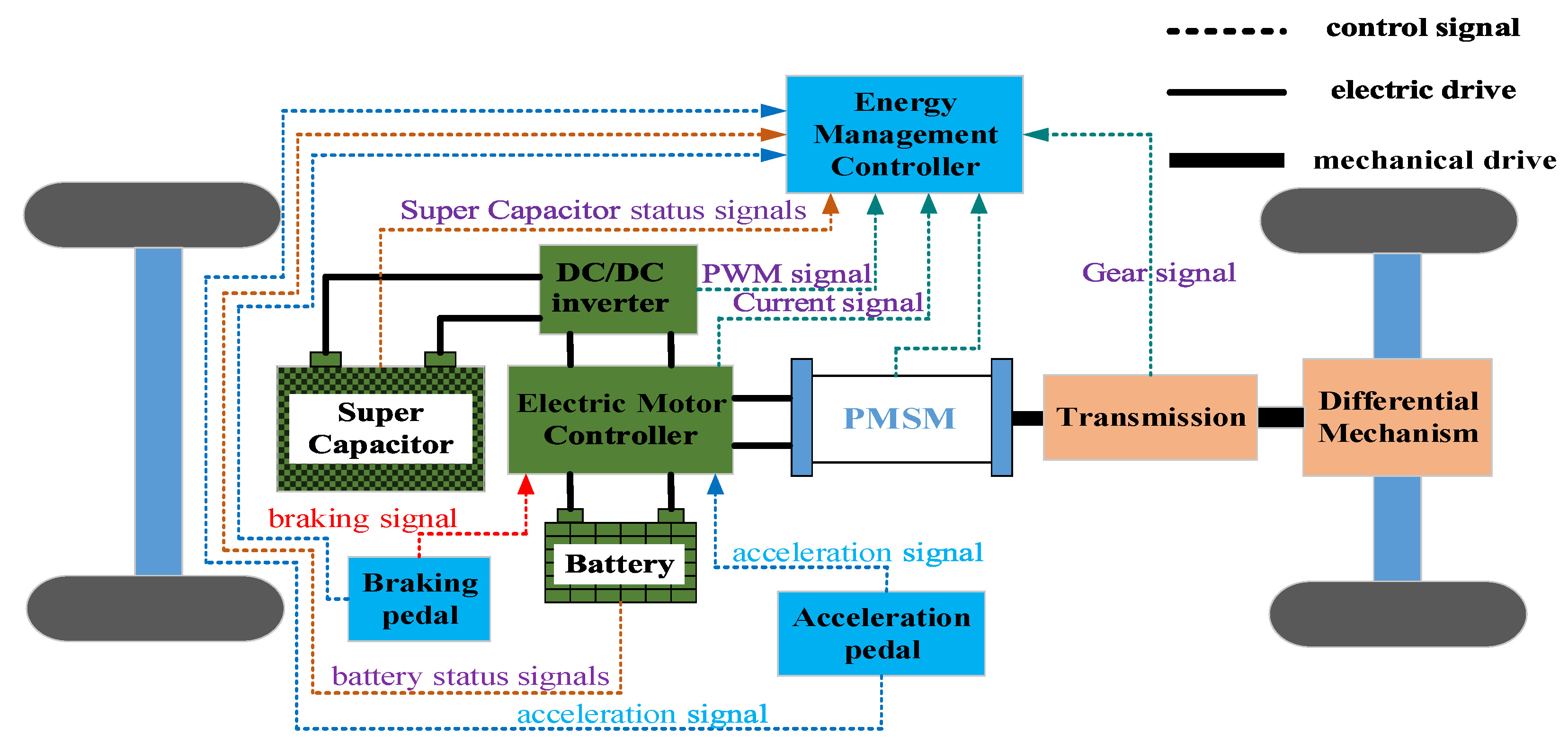
2. Composite Power System Structure

Considering cost and control factors comprehensively, the parallel composite power transmission structure was chosen [34,35]. Figure 1 illustrates the topology of the composite power supply, where a bidirectional DC/DC converter connects the super capacitor in parallel with the battery, while the power battery pack is directly linked to the motor controller. A system is established for electric vehicles operating under complex conditions, based on collected power demand signals and power state variables. Employing a multi-state model [36], we conduct model simulations to explore the impact of complex operating conditions on the system’s coupling characteristics.
The composite power system’s structure includes five primary operating modes:
(1)
Power battery pack alone drive mode: Utilized during normal driving conditions with low load power, where the power battery operates independently while the super capacitor remains idle.
(2)
Super capacitor single drive mode: Employed at vehicle startup or during rapid acceleration to alleviate the load on the power battery. Here, a high-power-density super capacitor serves as the primary power source, while the power battery remains in a standby state.
(3)
Co-drive mode of power battery pack and super capacitor: Activated during extended acceleration or steep slope climbing, where load power demand is high. Both the power battery and super capacitor work together to meet power requirements.
(4)
Regenerative braking energy recovery mode: Applied during deceleration, downhill driving, or braking to recover braking energy. Super capacitors are primarily used due to their short charging time and high-power density.
(5)
Super capacitors balance the chaotic and transient components in the load power: Employed when the vehicle experiences frequent load power fluctuations. Super capacitors help balance the chaotic and transient components, while the power battery handles low-frequency components. This power shunting enhances efficiency and prolongs the power battery’s lifespan.

3. Compound Power Simulation Model

3.1. Vehicle Dynamics Model

The driving force of the vehicle during operation is analyzed, and longitudinal dynamics are utilized to derive the vehicle’s driving dynamics equation on a smooth road [12].
F t = F f + F w + F i + F j
T e i g i 0 η t r = G f cos α + C D A u α 2 21.15 + G i + δ m d u a d t
where F t represents the driving force, F f denotes rolling resistance, F w signifies air resistance, F i represents gradient resistance, and F j accounts for acceleration resistance. Here, i g denotes the transmission ratio of the transmission; i 0 refers to the transmission ratio of the main reducer; η t represents the efficiency of the drivetrain; r is the wheel radius; G   is the car’s weight; f is the rolling resistance coefficient; C D   is the air resistance coefficient; A denotes the windward area; u a   is the car’s speed; i   signifies the road gradient; δ represents the conversion coefficient of the car’s rotating mass; m represents the car’s mass; d u a / d t denotes the driving acceleration; α represents the slope angle.
Power balance equation:
P = G f 3600 u a + C D A u a 3 76140 + G sin α 3600 u a + δ m d u a 3600 d t 1 η t ,
The required power of electric vehicles is matched through the maximum speed.

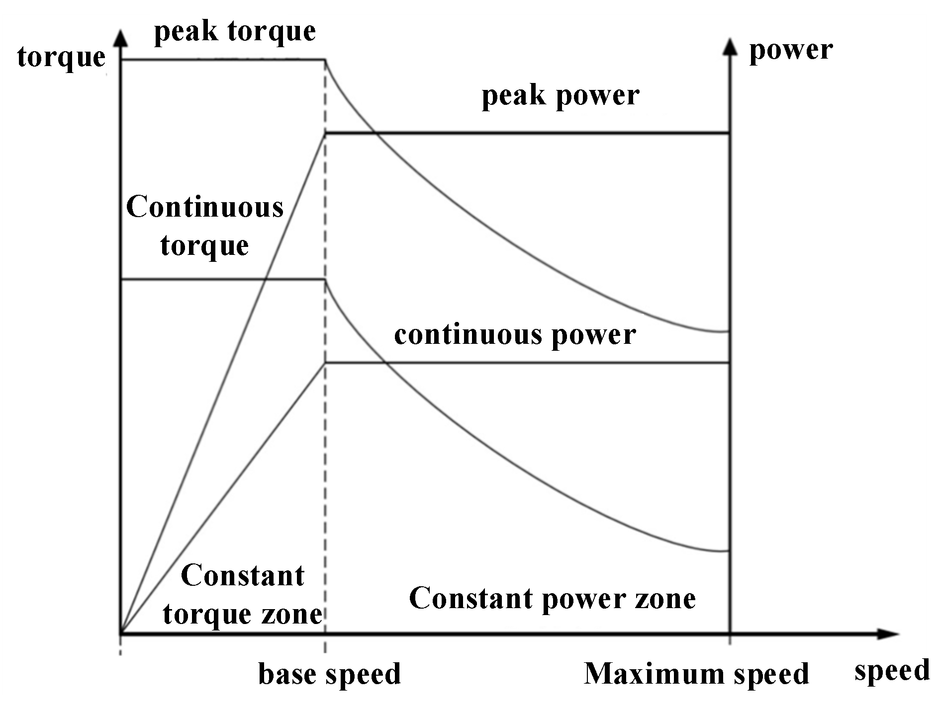
3.2. Calculation of Driving Motor Parameters

The permanent magnet synchronous motor (PMSM) is extensively used in the field of new energy vehicles, with its external characteristic curve depicted in Figure 2. Motor parameters are matched and calculated based on the motor’s external characteristic curve.
The peak speed of the driving motor corresponds to the highest speed in the constant power range. According to the correspondence between the maximum vehicle speed and the maximum motor speed
v max = ω max × r i 0 = 2 π × n max × r 60 × i 0 × 3.6 = 0.377 × r × n max i 0
Considering various performance indicators of power, the rated power of the electric motor PeP1. The peak power and rated power Pmax of the driving motor need to simultaneously meet the power requirements of the car at the highest speed P1, climbing on the slope with the highest gradient P2, and the required power during the acceleration process P3, i.e., Pmax ≥ max (P1, P2, P3).
P 1 = v max 3600 η T ( m g f + C D A v max 2 21.15 )
P 2 = v i 3600 η T ( m g f cos α + m g sin α + C D A v i 2 21.15 )
P 3 = m g f 3600 v c + C D A 3600 + 21.15 v c 3 + m 25920 η T v c 2
In the formula, vi represents the climbing speed, α denotes the climbing angle corresponding to the maximum slope, where vc is the accelerated speed, and t is the acceleration time.
The peak torque of the driving motor needs to meet the requirement of the maximum climbing slope, namely:
T max m g f c o n α + C D A 21.15 v i 2 + m g sin α η T i 0 × r
The matching results of motor parameters are shown in Table 1.

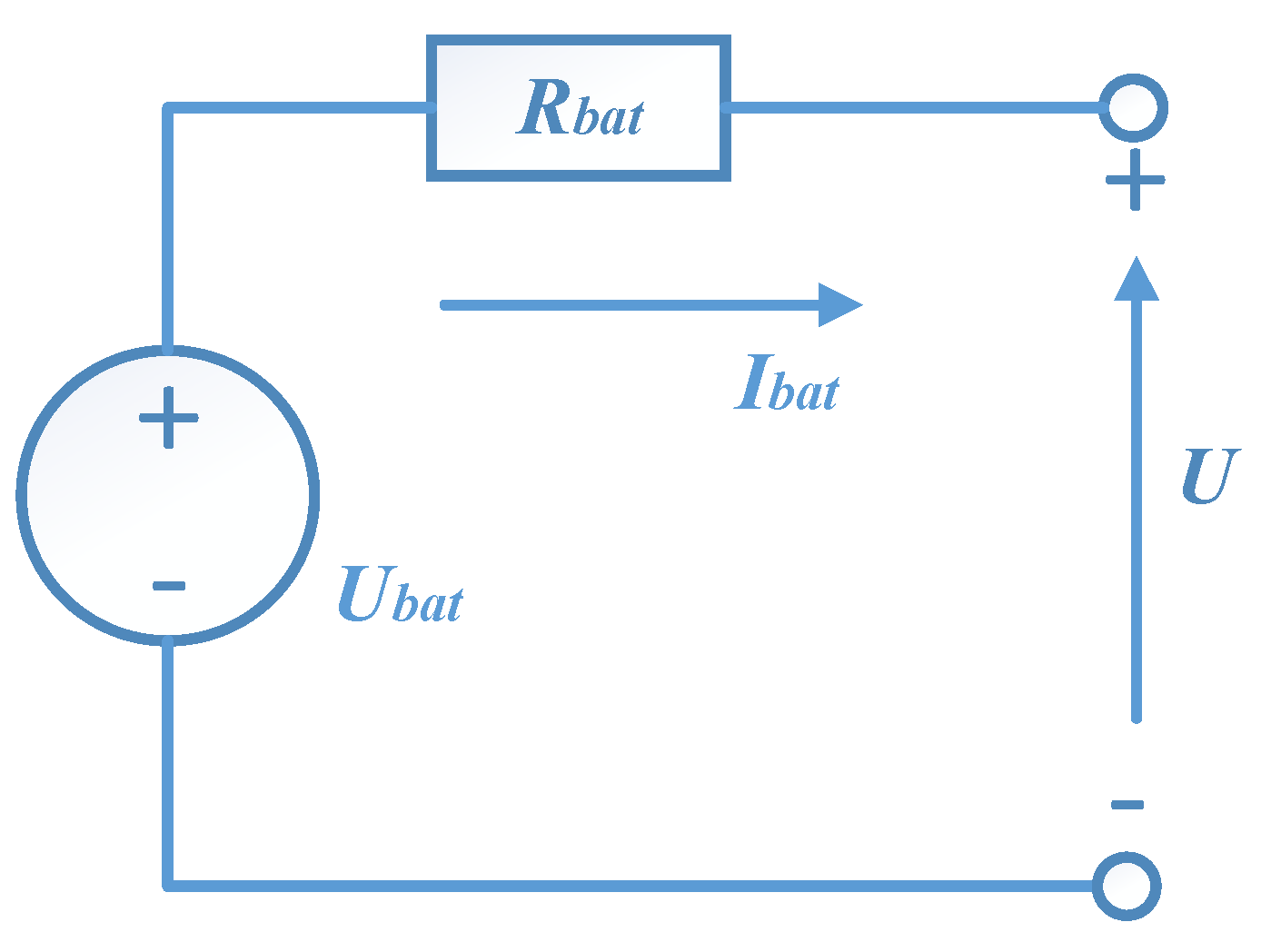
3.3. Power Battery Model

The power battery model adopts a simplified R i n t model that reflects internal resistance information, with its model parameters resembling the actual working performance of the battery [37]. As shown in Figure 3, it is simplified into an ideal voltage-internal resistance series equivalent circuit.
According to Kirchhoff’s voltage law, the load voltage and required power of a power battery can be expressed as:
U = U b a t I b a t × R b a t ,
P b a t = U × I b a t = U b a t × I b a t I b a t 2 R b a t ,
In the formula, P b a t represents the power of the power battery, where a positive value indicates the discharge state; U b a t is the open-circuit voltage of the battery; U denotes the battery output voltage; I b a t represents the battery current; R b a t is the equivalent internal resistance of the battery.
From the above formula, the battery current is:
I b a t = U b a t U b a t 2 4 P b a t R b a t 2 R b a t ,
The remaining capacity of the power battery is:
Q r e s i , t , τ = Q i n i t τ , i η c τ 0 t I b a t t d t ,
In the formula, Q r e s represents the remaining power of the power battery; Q i n i t denotes the power battery capacity; η c stands for the charging efficiency; τ represents the battery temperature; t signifies the battery discharge time. The state-of-charge formula of the power battery is:
B S O C = Q r e s Q i n i t = 1 η c τ 0 t I b a t t d t Q i n i t ,

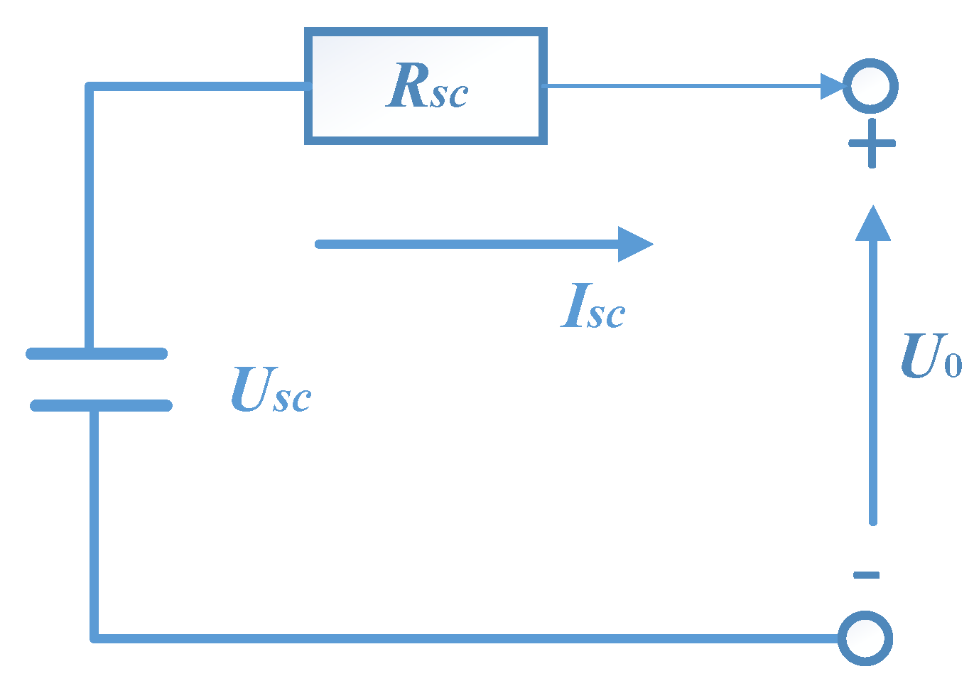
3.4. Super Capacitor Model

The super capacitor model adopts the classic RC circuit model, which has a simple structure and high accuracy. The simplified circuit structure is shown in Figure 4.
The super capacitor model mainly comprises terminal voltage, current module, capacity module, and so on. The working voltage range of the super capacitor is [ U m i n , U m a x ], and the capacity formula of the super capacitor is:
Q = C 1 U max U min 3600 ,
In the formula, C 1 represents the nominal capacity; U m a x stands for the maximum value of the working voltage of the super capacitor; U m i n denotes the minimum value of the working voltage of the super capacitor. Its state of charge is expressed by CSOC, and the calculation formula is:
CSOC = U U min U max U min
The working voltage across the capacitor is:
U t = C S O C × U m a x U m i n + U m i n ,

3.5. The Main Parameters of the Vehicle

Based on the reference model data and the parameter matching results, the simulation parameters of the hybrid electric vehicle are calculated, as shown in Table 1.

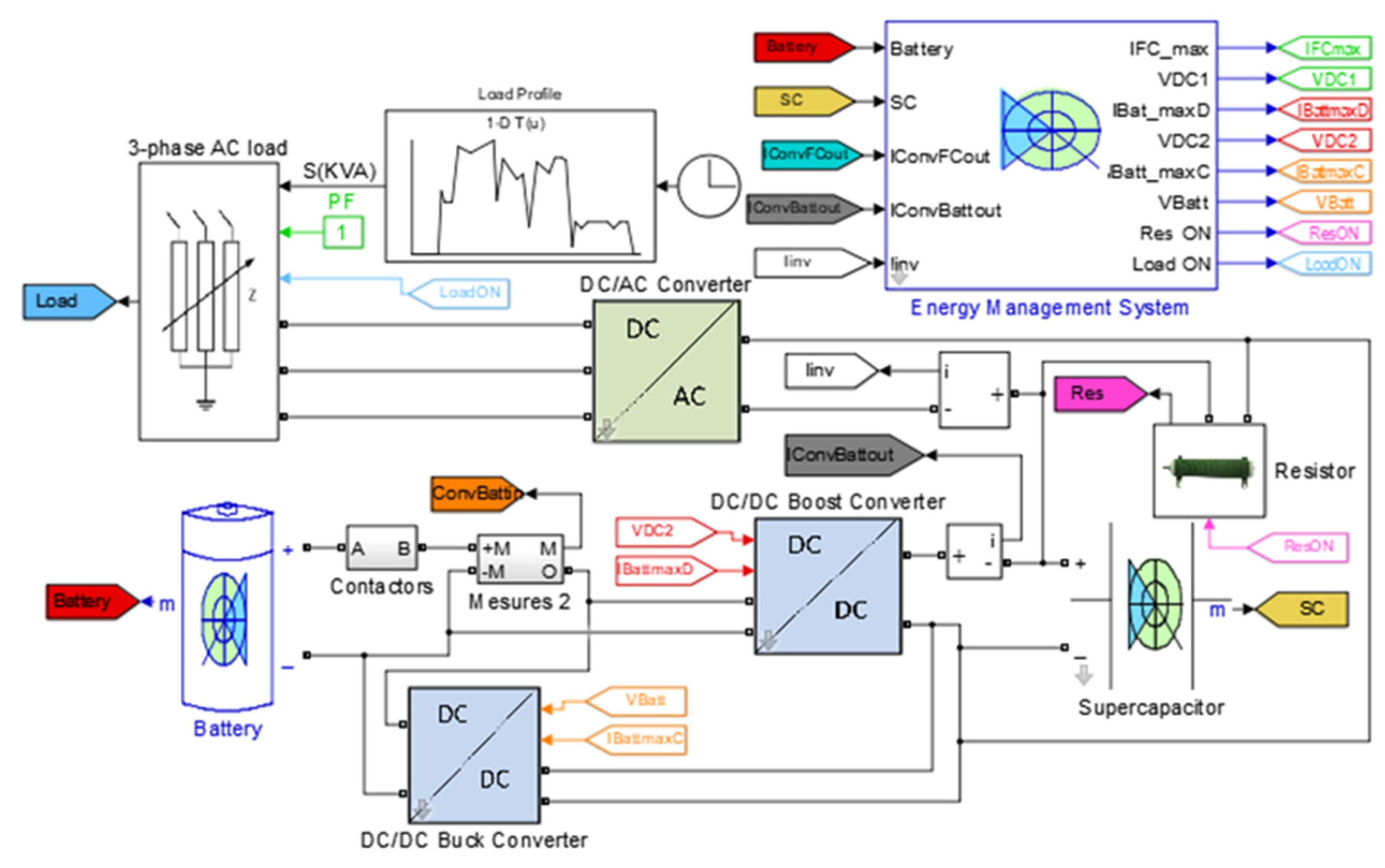
3.6. Establishment of a Vehicle Energy Management Model

Based on MATLAB 2019a/Simulink, we develop a simulation model for a hybrid electric vehicle system to explore the coupling characteristics and energy management strategies of multi-energy systems under complex operating conditions [38], as shown in Figure 5. The results from parameter matching are incorporated into the Powertrain Block set module, and the constructed model replaces the standard model framework. Subsequently, operational condition data are imported into the simulation model. Utilizing the Haar wavelet transform power shunt strategy, we extract the high-frequency component from the load demand power. Taking advantage of super capacitors’ characteristics in managing transient and instantaneous power, these components are effectively balanced by them. Meanwhile, the low-frequency component of the demand power is handled by the energy management controller. The Haar wavelet, known for having the shortest filter length in the time domain and the equivalence between wavelet transform and its inverse, is chosen for its suitability in implementing real-time online energy management strategies.

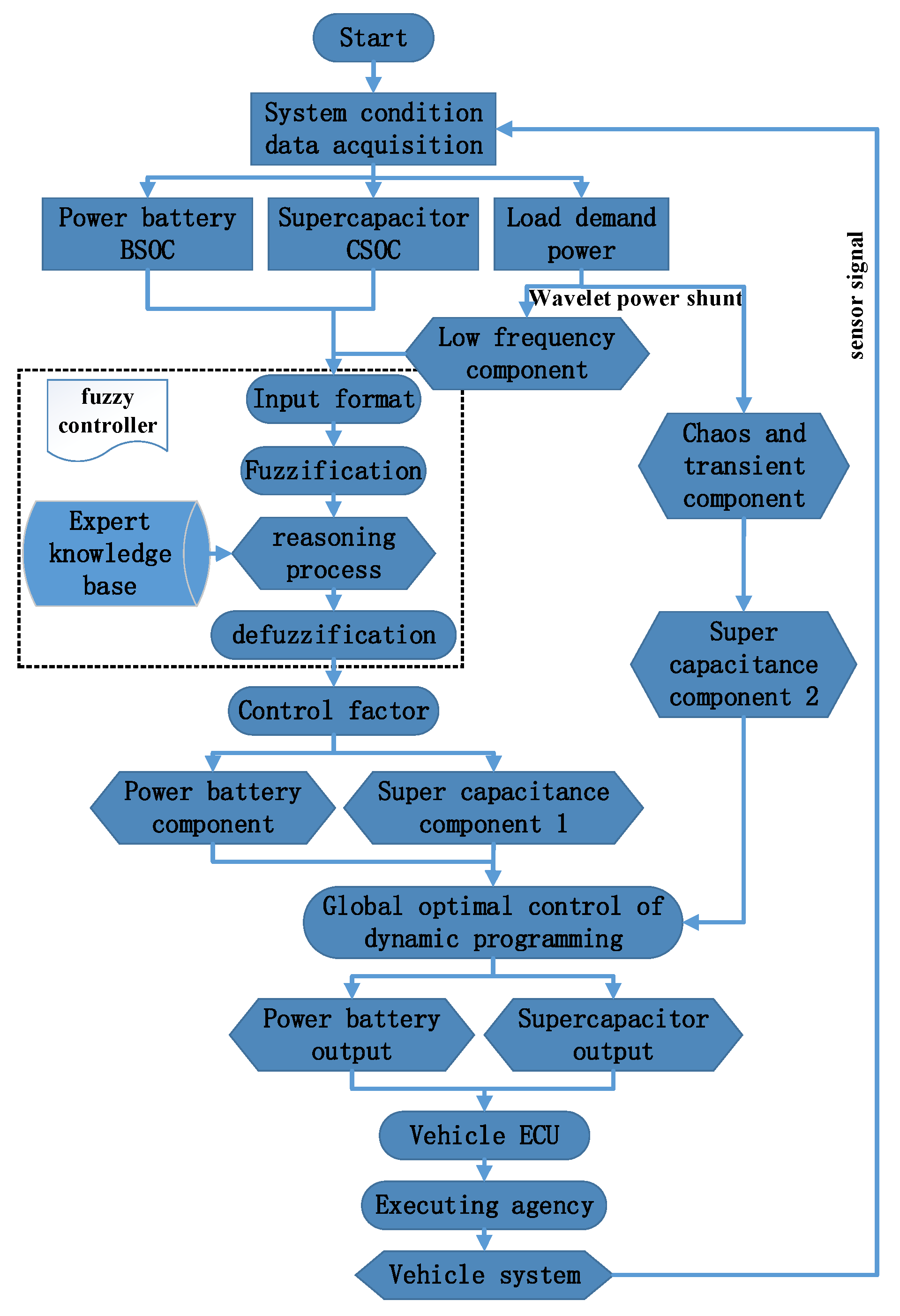
4. Composite Power Energy Management Strategy

In the simulation model, we collect real-time operational data and calculate the required load power and SOC values for both the power battery and the super capacitor [39]. Employing the wavelet transform for load power shunting allows for the extraction of high-frequency components from the overall power demand. Due to the advantages of super capacitors in terms of transient power, these transient components are balanced by super capacitors. The remaining low-frequency components of the power demand are allocated to the power lithium battery. The Haar wavelet has the shortest filter length in the time domain, and the Haar wavelet transform and its inverse transform are equivalent; this approach can simplify the composition of the program and improve the execution efficiency of the code, making it ideal for the implementation of real-time online energy management strategies. Hence, the core concept of our system’s energy management strategy is as follows: utilizing wavelet theory, we employ the super capacitor to balance the high-frequency component of power demand. The fuzzy logic controller utilizes the low-frequency component of load demand power and the SOC values of the supercapacitor and power battery as input parameters to determine output control factors [40]. Subsequently, after energy distribution using wavelet theory and fuzzy logic, we conduct global optimization through dynamic programming. The optimized output of the power battery and super capacitor forms the ECU system. During the vehicle’s operation, the sensor signals are acquired in real time and sent back to the data signal acquisition system. The flow chart of the energy management system is shown in the Figure 6 below.

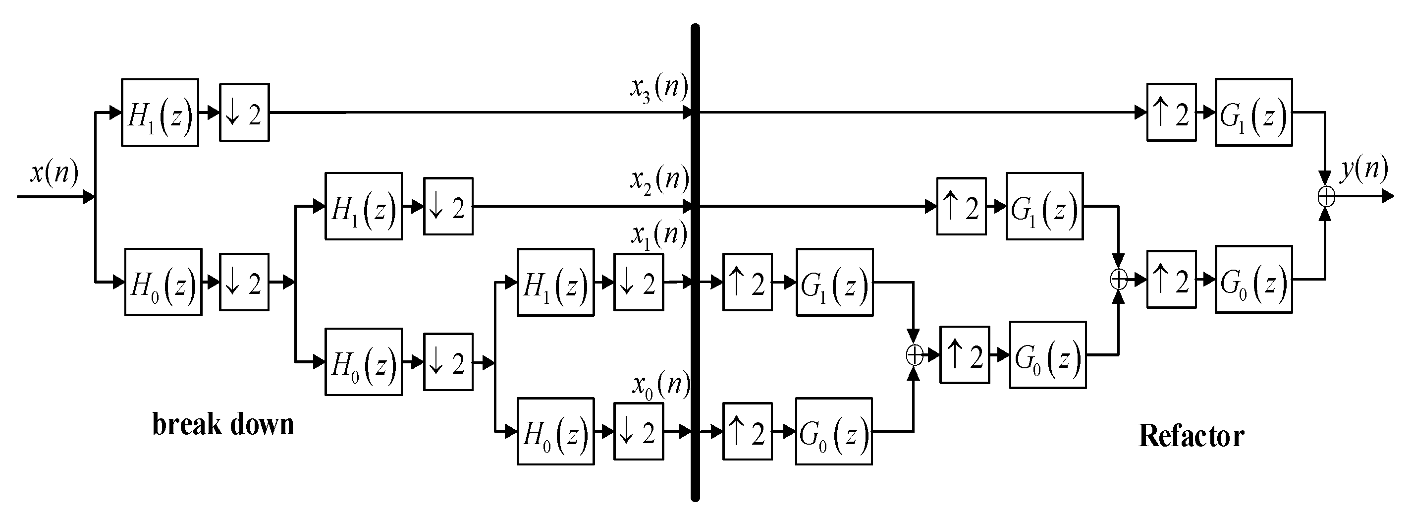
4.1. Power Split Based on Haar Wavelet Theory

This research focuses on load power distribution strategies grounded in wavelet transform theory. Super capacitors are adept at managing transient power. They handle the high-frequency component of load power, while the low-frequency components are primarily directed to the power battery. The Haar wavelet, characterized by its brief filter length in the time domain, simplifies programming and enhances code execution efficiency. It is well suited for real-time online energy management strategies [41]. The expression of the Haar wavelet is as follows:
ψ ( t ) = 1 t 0 , 1 / 2 1 t 1 / 2 , 1 0 other ,
The specific mathematical expressions of the high-pass and low-pass filters are:
H k ( z ) = 1 M z k + 1 z k ,   k = 1 , M
H 0 ( z ) = 1 M 1 + z 1 + + z M + 1 ,
Using the Haar wavelet transform, the original power demand signal x ( n ) is decomposed into a reference signal and detail signal through the low-pass filter H 0 ( z ) and high-pass filter H k ( z ) . The two signals are down sampled by a factor of M , reconstructed by the interpolation method of factor M , followed by reconstruction filter G k ( z ) , k = 1 , M 1 . Considering the simplicity of calculation and the principle of frequency limitation, in the composite power system, the third-order Haar wavelet is used to decompose and reconstruct the load demand power to realize the power distribution of the power supply, as shown in Figure 7 below. The sampling method decomposes and reconstructs the parameters.

4.2. Fuzzy Logic Control Scheme

Considering the specific conditions of vehicle operation, a dynamic adjustment control strategy based on adaptive fuzzy logic is proposed. This approach allows for the distribution of power between the power battery and the super capacitor while fulfilling the vehicle’s power requirements. Notably, it exhibits robustness and effectively tackles nonlinear and intricate challenges [42]. The control system considers the characteristics of random dynamic conditions and the real-time state parameters of the composite power supply during vehicle operation. It employs the super capacitor to balance the high-pass component G 1 ( z ) after load power reconstruction, while the low-pass component G 0 ( z ) acts as input power for the fuzzy logic controller.
Pr = Pbat + Pcap,
In the formula, P r represents the low-pass component of vehicle demand power, P b a t provides power for the battery, and P c a p provides power for the capacitor.
Let us define K b a t as the battery power scale factor, which represents the proportion of battery output power, namely:
K b a t = P b a t P r ,
The main factors that affect system power distribution are load demand power, low-pass and high-pass components of power, as well as the state of charge of batteries and super capacitors. A power distribution scheme is established based on the principle of fuzzy logic. The fuzzy control system takes inputs, such as the load demand power low-pass component P r , the battery state of charge (BSOC) and the super capacitor state of charge (CSOC) value. The output is the battery power distribution factor K b a t . When the actual control system is working, the output power of the power battery is K b a t × G 0 ( z ) , and the output power of the super capacitor is G 1 z + ( 1 K b a t ) × G 0 ( z ) .

4.3. Fuzzy Controller Design

The fuzzy logic controller is devised based on the aforementioned control scheme, employing the Mamdani architecture featuring a single output and three inputs. P r , BSOC and C S 0 C are utilized as the input parameters of the fuzzy logic controller, while K b a t serves as the output parameter of the controller.

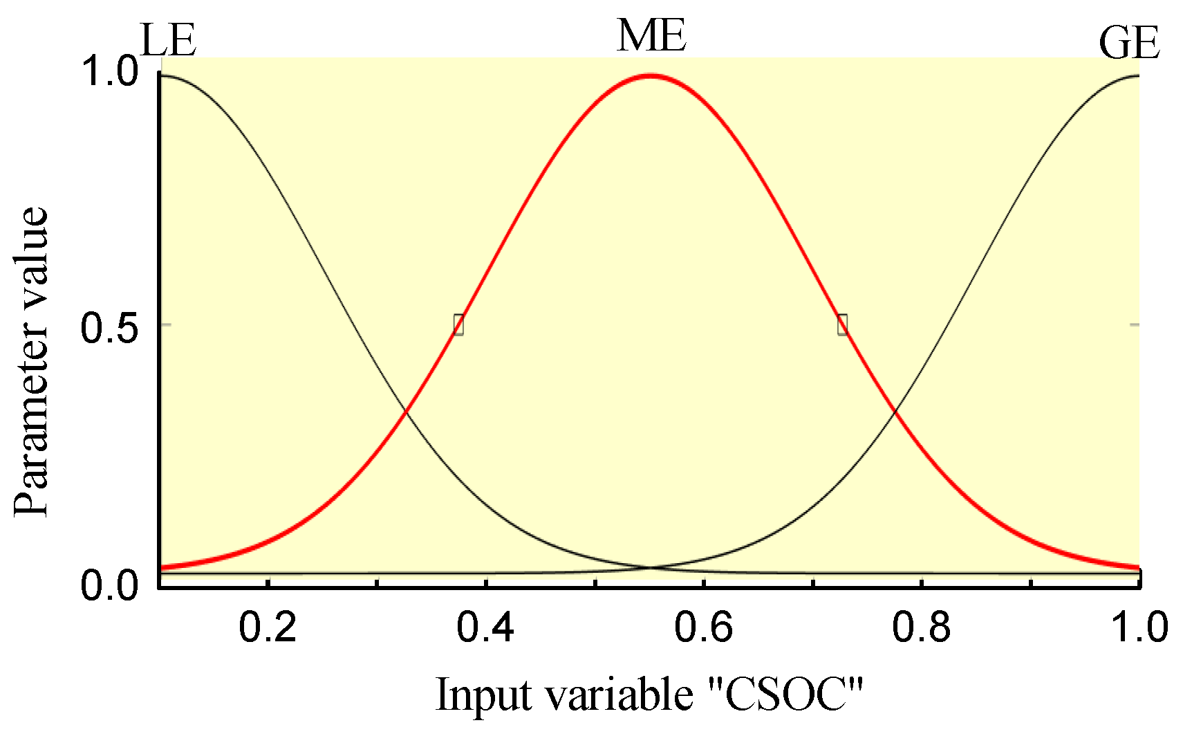
4.3.1. The Domain of Control Variables and the Determination of Fuzzy Subsets

Theoretically, the domain of the membership function of the required power P r is [−1, 1]. However, considering that the regenerative braking power of the motor is less than the maximum power of the motor drive, the domain of P r is adjusted to [−0.3, 1] and divided into six subsets: P r = [NB NM NS ZE PS PM PB].
The fundamental domain of the battery (BSOC) and super capacitor (CSOC) lies between [0, 1]. Upon analyzing the characteristics of the power battery and super capacitor, it is noted that when the value of battery SOC is less than 0.2, the internal resistance of the power battery changes greatly. It affects the charging and discharging efficiency. Hence, the range of BSOC and CSOC is adjusted to [0.2, 1.0] and divided into three subsets: BSOC = [LE ME GE], CSOC = [LE ME GE].
The basic domain of the scale factor K b a t is set to [0, 1], divided into five subsets: K b a t = [LE ML ME MB GE]. The fuzzy parameters of the variable are determined according to the domain of the variable, as shown in Table 2, Table 3 and Table 4.

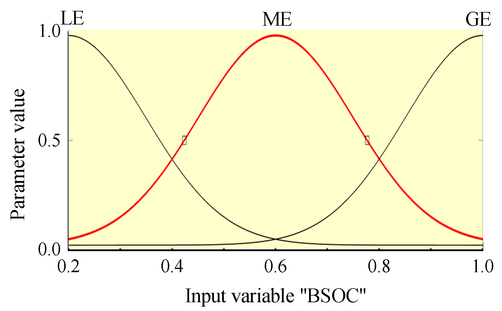
4.3.2. Determination of Membership Function

The shape of the membership function significantly influences the controller’s sensitivity. The triangular membership function offers simplified calculation, rapid response, and effective control performance, making it suitable for representing the demand power P r . Conversely, the Gaussian membership function, characterized by its symmetrical distribution and smooth transitions controlled by parameters σ and c , is chosen for the power battery SOC, super capacitor SOC, and power output   K b a t . This selection is based on the Gaussian function’s favorable attributes, including its large symmetrical distribution ratio and smooth transition characteristics. Figure 8 illustrates the membership function for the required power P r .
The membership degrees for the power battery SOC, super capacitor SOC, and scale factor   K b a t are depicted in Figure 9, Figure 10 and Figure 11.

4.4. Fuzzy Rule Establishment

After filtering out chaotic and transient components of the required power, various control schemes are adopted according to the difference in the steady-state variable P r of the required power. The formulation of a fuzzy strategy is simplified into four modes:
(1)
When the super capacitor CSOC is high, if the BSOC is low and P r is not very high, the super capacitor solely provides power. If P r is high, regardless of the power battery BSOC level, both the power battery and the super capacitor provide the power for the vehicle.
(2)
When the super capacitor CSOC is in an intermediate state, if P r is low, either the power battery or the super capacitor shares the power output. If the BSOC is low and the CSOC is high, the super capacitor supplies energy independently. If P r is high, then both the power battery and super capacitor together carry out energy output.
(3)
When the CSOC is low, irrespective of the P r level, all energy is supplied by the power battery. When the power demand of the vehicle is small and the power battery has sufficient power, the battery can provide energy to the super capacitor to supplement its necessary power.
(4)
When P r is less than 0, it is the braking energy recovery mode, and the super capacitor is used for braking energy recovery. The control strategy is formulated differently according to the SOC value of the power battery and the SOC value of the super capacitor: if the CSOC is relatively low, the super capacitor recovers the braking energy and charges the power battery after it is fully charged; if the BSOC is low and the CSOC is high, the energy recovered by the super capacitor will charge the power battery; if the BSOC and CSOC are both high, the super capacitor and the power battery are allowed to be appropriate charge.
According to the above rules, the fuzzy logic control rules are formulated as shown in Table 5.

4.5. Fuzzy Control System Model

A three-input single-output variable model was constructed using the Fuzzy Logic Controller module. The compound power fuzzy control system, depicted in Figure 12, was then established to conduct simulation experiments for the control strategy of compound power electric vehicles.

5. Simulation Analysis of Control Strategy

The simulation experiment was conducted under the standard UDDS working condition, as shown in Figure 13. This condition has a cycle time of 1369 s, covering a driving distance of 11.99 km, with a maximum speed of 91.25 km/h and an average speed of 31.51 km/h. The vehicle stops for a total of 259 s, occurring 17 times during the cycle. Utilizing the previously developed energy management strategy, simulations were performed for both single energy source and compound power electric vehicles employing the fuzzy control strategy.

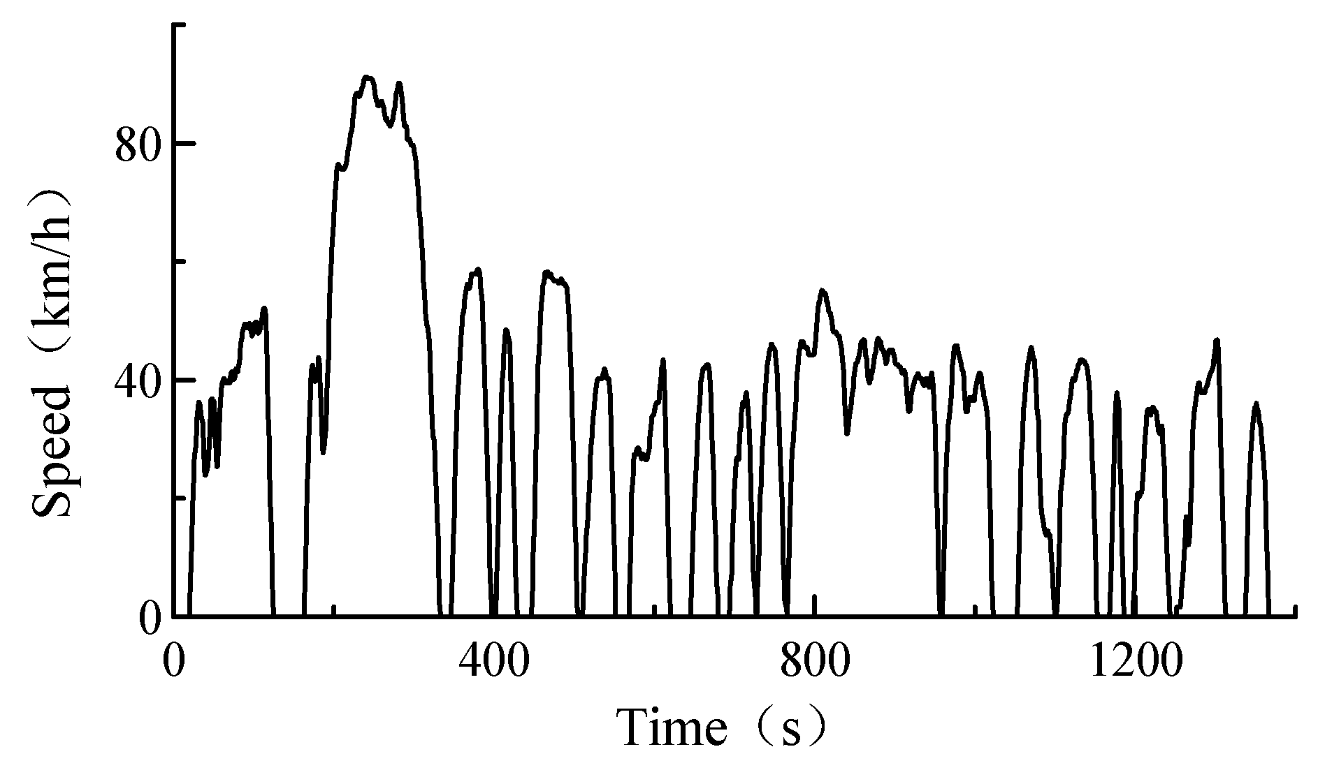
5.1. Wavelet Theory Power Split

The standard UDDS operating condition data curve was loaded into the simulation model to analyze the system demand profile. Based on the wavelet transform algorithm to separate the high- and low-frequency demand power and based on the MATLAB code to determine the optimal three-layer decomposition threshold, the corresponding optimal values of d1, d2, and d3 are 5.3709, 6.7233, and 7.1788; the corresponding load power curve after three-layer Hart wavelet processing is shown in Figure 14. Following the optimal threshold three-layer Haar wavelet processing, the required power is allocated, and some chaotic and transient components are balanced with super capacitors to prevent the power battery from processing the rapidly changing power demand and improve the life of the battery system and the economy of the vehicle. The a3 curve is the low-frequency part after the UDDS working condition power is shunted, and this component is used as the input variable of the load demand power in the fuzzy logic controller. The super capacitor is used as a power buffer to absorb the transient fast power variable, that is, the power of the d1 to d3 curve in the figure, which extends the life of the power battery and improves the energy efficiency of the system.

5.2. Fuzzy Logic Control Simulation

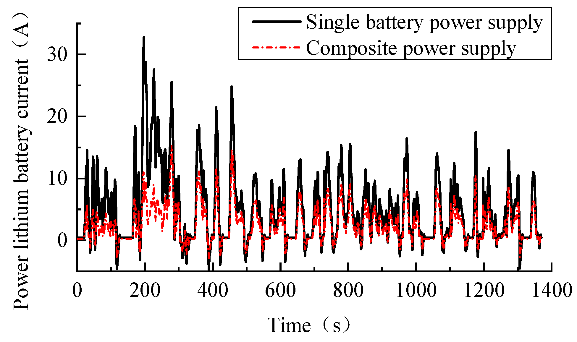
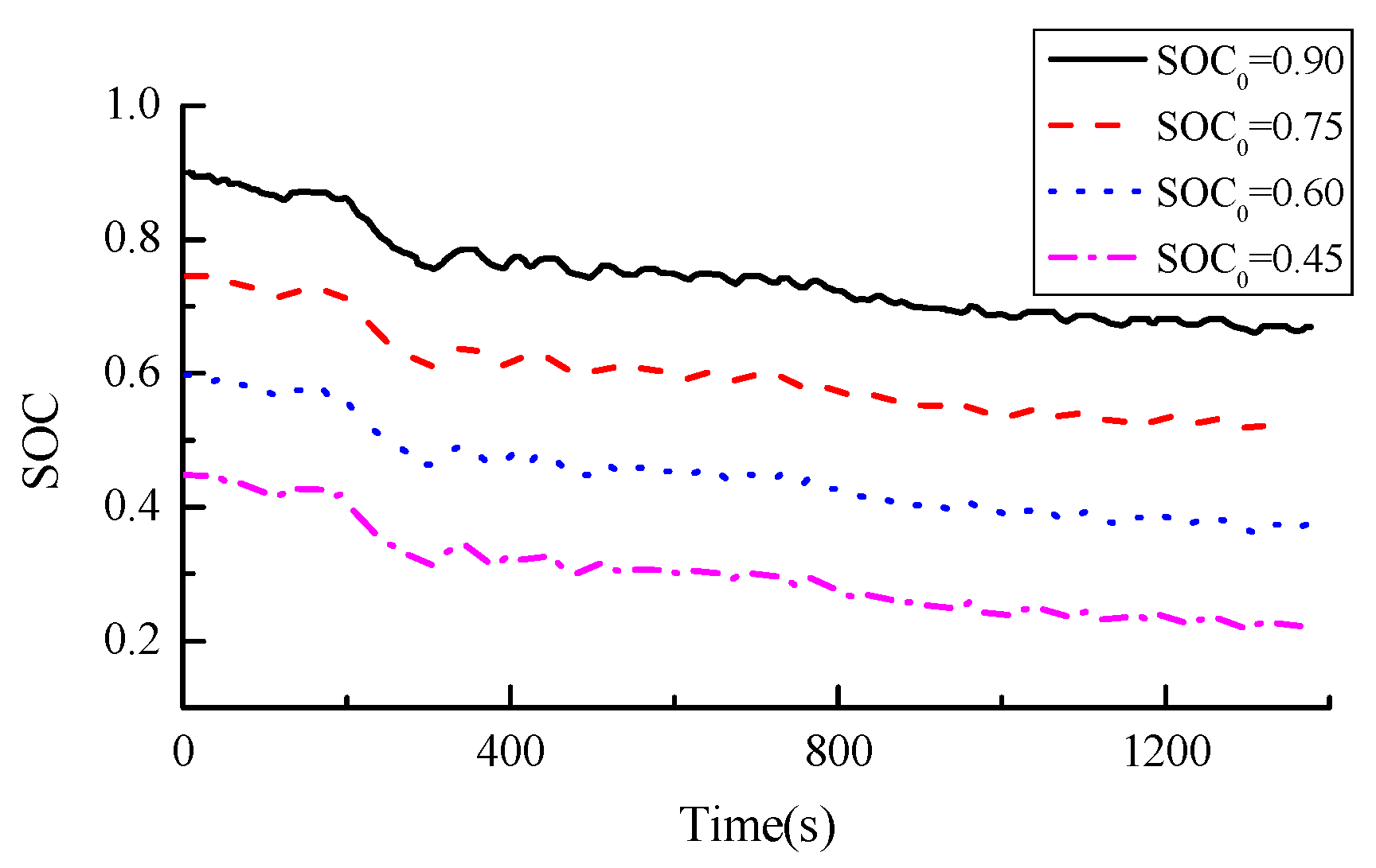
5.2.1. Comparative Analysis of Power Battery SOC and Current Value

Under UDDS cycle conditions, each power system is matched with the same capacity. Comparing the simulation results in Figure 15, it is evident that the SOC of the power battery in the single energy source system decreased to 0.668, while the SOC of the power battery in the composite power system decreased to 0.69. This indicates that the SOC of the power battery in the composite power system decreased by 12.5%, showcasing an enhancement in efficiency.
The driving range of an electric vehicle is a crucial metric. Figure 16 illustrates that the peak output current of a single power source reaches 36 A, significantly affecting the power battery. In contrast, the peak output current of the power battery in the composite power system is 15 A. This indicates that the composite power system effectively mitigates the impact of high-current charging and discharging on the power battery, thus safeguarding its longevity and extending the overall life of the power battery.

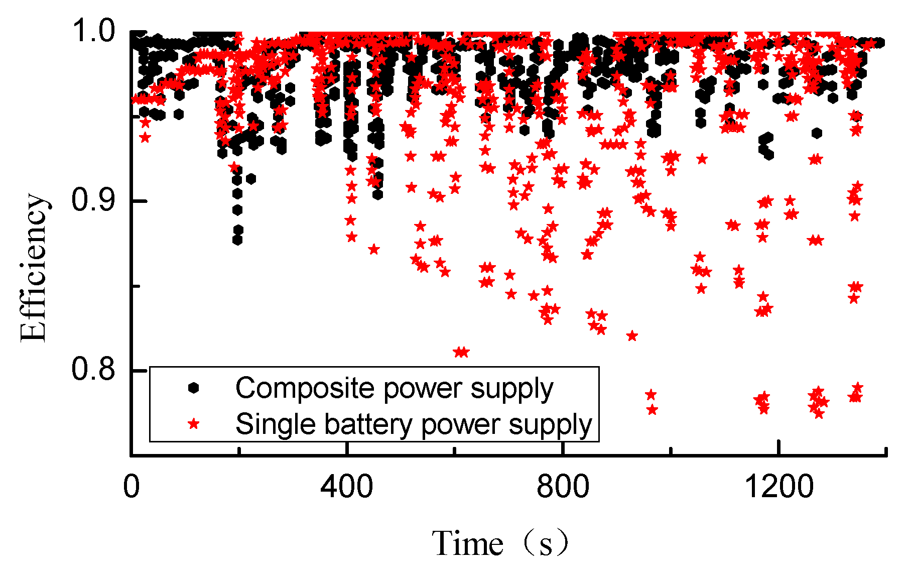
5.2.2. Comparative Analysis of Discharge Efficiency

Figure 17 presents a comparison curve of the discharge efficiency of the power battery between a single power supply and a composite power supply pure electric vehicle operating under UDDS conditions. Notably, the discharge efficiency of the power battery in a composite power electric vehicle exhibits higher, denser, and more stable performance compared to that of a single power battery system.

6. Optimizing the Control Strategy Based on the Dynamic Programming Algorithm

To obtain optimal control, the best distribution of power and energy must be achieved within the composite power system. While fuzzy logic control is well suited for instantaneous optimal power distribution, it struggles to maintain optimal control throughout the entire cycle [43]. This section explores global optimal control of the composite power system using the dynamic programming (DP) algorithm. With the objective of minimizing power battery losses, we dynamically plan the control strategy based on real-time state parameter values under UDDS driving conditions. This ensures the optimal distribution of power between the power battery and the super capacitor [44].

6.1. Optimize the Objective Function

By considering the power loss of the power battery in the composite power system as the cost function, our optimization objective is to minimize this cost function. We employ the vehicle power balance equation to determine the power demand of the vehicle’s composite power system during cycle driving conditions, thereby achieving the optimal distribution of energy between the power battery and the super capacitor. The optimization process can be described as follows: the system optimization path is divided into multiple stages and searches for the optimal control amount from the initial state to the final state according to the required power of each system section. This approach aims to minimize battery energy loss throughout the entire standard operational condition [43]. The optimization objective function is:
J = k = 0 N 1 f b a t x ( k ) , u ( k ) , k k ,
In the formula, x ( k ) and u ( k ) , respectively, represent the state variables and control variables of the system.
When the power of the battery or super capacitor is determined at any given moment, the other power is automatically determined. Consequently, the control system operates in a univariate mode. The control variable is expressed in terms of the required power of the power battery. A constraint function is derived, with the power battery and super capacitor serving as state variables for the global optimization of the system [45], as indicated in the following formula:
u ( k ) = P b a t ( k ) ,
x ( k ) = BSOC ( k ) , CSOC ( k ) ,
In the formula, x ( k ) = g [ x ( k 1 ) , u ( k 1 ) ], g is the state transition function.
x ( k ) = BSOC ( k + 1 ) = BSOC ( k ) Δ t Q c a p U o c CSOC ( k + 1 ) = CSOC ( k ) + CSOC ( k ) U max + [ CSOC ( k ) U max ] 2 4 P c a p R c a p 2 R c a p C c a p U max ,

6.2. Optimization Constraint Problems and Solutions

The optimization problem is subject to the performance constraints of the power source, including the state constraints of the power battery and super capacitor SOC, as well as their respective power constraints. The constraints are as follows:
BSOCmin ≤ BSOC(k) ≤ BSOCmax,
CSOCmin ≤ CSOC(k) ≤ CSOCmax,
Pbat_minPbat(k) ≤ Pbat_max,
Pcap_minPcap(k) ≤ Pcap_max,
In the formula, P c a p _ m i n and P c a p _ m a x represent the minimum and maximum power of the super capacitor, respectively, while P b a t _ m i n and P b a t _ m a x represent the minimum and maximum power of the power battery, respectively. Combining Equations (20)–(23), these constraints can be folded into a single constraint.
The dynamic programming method uses the reverse calculation method. When the initial state is given, we calculate from k = N , and then calculate the optimal decision and function of each stage. After the reverse calculation is completed, a forward calculation is needed, and the reverse calculation result is used as the known quantity. The optimal control quantity at each moment is calculated by interpolating the Interp function.
Before executing dynamic programming, as a part of DP, the equation must be converted from continuous space to discrete space. The battery charge state is simply divided into 72 possibilities, and the value function V and the optimal controller u_star are assigned in advance.
Suppose the control quantity at time m is P b a t ( m ) , and the state B S O C ( m + 1 ) at time ( m + 1 ) can be obtained according to the system state variables. However, B S O C ( m + 1 ) may not precisely match a specific time ( m + 1 ) state value, as the value function V is defined on the SOC grid. Interpolation between grid points is conducted to determine the corresponding battery energy loss J ( m ) .

6.3. Comparative Analysis of Optimization Results

To validate the optimization effectiveness of the energy management system controlled by DP, the dynamic programming program was compiled through Python 3.8, and the program was run based on Anaconda 3 2019. 10 software.
Figure 18 illustrates the power output comparison curve of the power battery and super capacitor after DP-optimized control. Under the high-demand power of electric vehicles and frequent load power conversion, the composite power system uses super capacitors to weaken the load borne by the power battery, which plays a “peak shaving” role. Additionally, when the required power value is less than zero, the super capacitor is used to recover braking energy. During the whole cycle, the working power of the power battery is stable, and the peak value is reduced to prevent the impact of high current on the power battery, thereby safeguarding it and enhancing the energy utilization efficiency of the system.
Figure 19 depicts a comparison chart of the change curve of the power battery SOC value under three working conditions. In the 1369 s cycle working condition, under dynamic programming optimization control, the SOC of the power battery drops to 0.724, which is compared with the fuzzy control of a single battery. In other words, the DP optimization control increases the SOC of the battery by 25%. Compared with the fuzzy control of the compound power supply, the SOC of the battery increases by 14.2% in the dynamic programming algorithm. The energy efficiency of electric vehicles using composite power sources has been significantly improved, and the designed control based on the DP algorithm can maximize the energy utilization rate of the vehicle and increase the driving range of the vehicle.
In order to verify the effectiveness of the DP algorithm, aside from horizontally comparing the composite power system (with an initial power battery SOC of 0.9) under different control strategies, longitudinal comparisons are also simulated under the same control strategy with different initial values. As illustrated in Figure 20, the overall SOC of the power battery remains relatively stable, with minor fluctuations along the downward curve due to frequent changes in load power and the system’s engagement in braking energy recovery.
Table 6 presents the simulation outcomes of two distinct control strategies. The data indicate that the power consumption per 100 km of the vehicle following dynamic programming optimization is marginally lower compared to that of the fuzzy control strategy, decreasing by 1.632 kWh, equivalent to a 14.7% reduction in power consumption. Consequently, optimization enables finer adjustments in power distribution between the power battery and the super capacitor, leading to reduced energy consumption and improved vehicle economy.

7. Conclusions

Under the fuzzy logic control strategy, the composite power system demonstrates a 12.5% increase in the SOC of the power battery compared to a single battery power source, with the SOC decreasing from 0.9 to 0.69 under 1369 s cycle conditions. Additionally, the composite power system exhibits a nearly 20 A reduction in peak power battery current compared to the single power system. The integration of super capacitors in the composite power system enhances power battery charging and discharging efficiency, leading to a reduction in the number of power battery discharge cycles and discharge current.
With DP optimization control, the power battery’s SOC decreases from 0.9 to 0.724. Compared to single battery fuzzy control, the DP algorithm increases the power battery’s SOC by 25%. In comparison to fuzzy control of the composite power supply, the power battery’s SOC increases by 14.2%. From an economic perspective, the vehicle’s power consumption per 100 km after DP optimization decreases by 14.7% compared to the fuzzy control strategy. This enhances the energy utilization of the power supply system and extends the vehicle’s driving range.
Therefore, considering the impact of chaotic and transient power demands on the coupling characteristics of a power battery system during the energy management process of a hybrid power system, this study achieves mathematical statistics and probability distribution methods to achieve power shunting. This approach violates the common control strategy concept in existing research. The power battery processes most of the low-frequency power demands from wavelet decomposition. Super capacitors provide the high-frequency part of the power demand. This scheme improves energy utilization and provides a new low-cost idea for developing an energy management system for hybrid power systems.
While existing research on composite power sources has primarily focused on fuel cells, power batteries, and super capacitor systems, this study investigates a composite power system consisting of power batteries and super capacitors. This system offers great application prospects in the field of heavy-duty vehicles. Our team focuses on researching special-purpose vehicles. However, the existing design schemes cannot be directly applied to heavy-duty vehicles. Therefore, this research explores the theory of composite power systems for passenger cars, laying a theoretical foundation for future research on composite power systems for special-purpose vehicles.

Author Contributions

Conceptualization, Z.Z.; Methodology, J.T.; Software, J.Z.; Validation, T.Z. All authors have read and agreed to the published version of the manuscript.

Funding

This research was funded by Regional Innovation and Development Funds from the National Natural Science Foundation of China (U20A20332).

Data Availability Statement

The data presented in this study are available on request from the corresponding author. The data are not publicly available due to the confidential nature of the research project.

Conflicts of Interest

The authors declare no conflict of interest.

Nomenclature

SOCState of Charge of the Power Battery
MGsMicrogrids
S.E.Hub Smart Energy Hub
IDSMIntegrated Demand Side Management
CCCloud Computing
SCSuper Capacitor
NENash Equilibrium
DRLDeep Reinforcement Learning
ATSACAutomatic Tuned Soft Actor-critic
HEVHybrid Electric Vehicle
LiBLithium-ion Battery
PMSMPermanent Magnet Synchronous Motor
PWMPulse Width Modulation
BSOCBattery State of Charge
CSOCSuper Capacitor State of Charge
UDDSUrban Dynamometer Driving Schedule
DPDynamic Programming
ECUElectronic Control Unit

References

  1. Lin, Y. Research on Fuzzy Control of Energy Management of Dual Energy Source Pure Electric Vehicles; Chang’an University: Xi’an, China, 2021. [Google Scholar]
  2. Zhang, C. Research on Matching and Control Theory of Pure Electric Vehicle Composite Power Supply; Jilin University: Changchun, China, 2017. [Google Scholar]
  3. Liu, T.; Tan, W.; Tang, X.; Zhang, J.; Xing, Y.; Cao, D. Driving Conditions-driven Energy Management Strategies for Hybrid Electric Vehicles: A Review. Renew. Sustain. Energy Rev. 2021, 151, 111521. [Google Scholar] [CrossRef]
  4. Barresi, M.; Colnago, S.; Ferri, E. Sizing and Energy Management Strategy of a Hybrid Energy Storage System for EVs. In Proceedings of the IEEE Vehicle Power and Propulsion Conference (VPPC), Merced, CA, USA, 1–4 November 2022; pp. 1–6. [Google Scholar]
  5. Tang, X.; Chen, J.; Liu, T.; Qin, Y.; Cao, D. Distributed Deep Reinforcement Learning-based Energy and Emission Management Strategy for Hybrid Electric Vehicles. IEEE Trans. Veh. Technol. 2021, 70, 9922–9934. [Google Scholar] [CrossRef]
  6. Sun, H.; Fu, Z.; Tao, F.; Zhu, L.; Si, P. Data-driven Reinforcement-learning-based Hierarchical Energy Management Strategy for Fuel Cell/Battery/Ultracapacitor Hybrid Electric Vehicles. J. Power Sources 2020, 455, 227964. [Google Scholar] [CrossRef]
  7. Geng, W.; Lou, D.; Wang, C.; Zhang, T. A Cascaded Energy Management Optimization Method of Multimode Power-split Hybrid Electric Vehicles. Energy 2020, 199, 117224. [Google Scholar] [CrossRef]
  8. Sina, B.; Mehdi, N.; Glareh, A.; Matthew, J.R. The Plugin Hybrid Electric Vehicle Routing Problem: A Power-management Strategy Model. Transp. Res. Part C 2020, 111, 318–333. [Google Scholar]
  9. Wu, X.; Gu, Y.; Mjia, X. Adaptive Energy Management Strategy for Extended-range Electric Vehicle Based on Micro-trip Identification. IEEE Access 2020, 8, 176555–176564. [Google Scholar] [CrossRef]
  10. Fakir, C.E.; Idrissi, Z.E.; Lassioui, A.; Fatima, Z.B.; Gaouzi, K.; Fadil, H.E.; Aziz, R. Adaptive Nonlinear Control of Salient-pole PMSM for Hybrid Electric Vehicle Applications: Theory and Experiments. World Electr. Veh. J. 2023, 14, 30. [Google Scholar] [CrossRef]
  11. Zhang, S.; Zhuan, X. Study on Adaptive Cruise Control Strategy for Battery Electric Vehicle Considering Weight Adjustment. Symmetry 2019, 11, 1516. [Google Scholar] [CrossRef]
  12. Da Silva, S.F.; Eckert, J.J.; Silva, F.L.; Silva, L.C.; Dedini, F.G. Multi-objective Optimization Design and Control of Plug-in Hybrid Electric Vehicle Powertrain for Minimization of Energy Consumption, Exhaust Emissions and Battery Degradation. Energy Convers. Manag. 2021, 234, 113909. [Google Scholar] [CrossRef]
  13. Li, J.; Wu, X.; Xu, M.; Liu, Y. A Real-time Optimization Energy Management of Range Extended Electric Vehicles for Battery Lifetime and Energy Consumption. J. Power Sources 2021, 498, 229939. [Google Scholar] [CrossRef]
  14. Zhang, Z.; Zhang, T.; Hong, J.; Zhang, H.; Yang, J.; Jia, Q. Double Deep Q-network Guided Energy Management Strategy of a Novel Electric-hydraulic Hybrid Electric Vehicle. Energy 2023, 269, 126858. [Google Scholar] [CrossRef]
  15. Joud, L.; Da Silva, R.; Chrenko, D.; Kéromnès, A.; Le Moyne, L. Smart Energy Management for Series Hybrid Electric Vehicles Based on Driver Habits Recognition and Prediction. Energies 2020, 13, 2954. [Google Scholar] [CrossRef]
  16. Zhang, R.; Tao, J.; Zhou, H. Fuzzy Optimal Energy Management for Fuel Cell and Super Capacitor Systems Using Neural Network Based Driving Pattern Recognition. IEEE Trans. Fuzzy Syst. 2019, 27, 45–57. [Google Scholar] [CrossRef]
  17. Thirugnanam, K.; El Moursi, M.S.; Khadkikar, V. Energy Management of Grid Interconnected Multi-microgrids Based on P2P Energy Exchange: A data driven approach. IEEE Trans. Power Syst. 2020, 36, 1546–1562. [Google Scholar] [CrossRef]
  18. Sheikhi, A.; Rayati, M.; Bahrami, S. Integrated Demand Side Management Game in Smart Energy Hubs. IEEE Trans. Smart Grid 2015, 6, 675–683. [Google Scholar] [CrossRef]
  19. Wang, K.; Wang, W.; Wang, L.; Li, L. An Improved SOC Control Strategy for Electric Vehicle Hybrid Energy Storage Systems. Energies 2020, 13, 5297. [Google Scholar] [CrossRef]
  20. Corinaldesi, C.; Lettner, G.; Schwabeneder, D.; Ajanovic, A.; Auer, H. Impact of Different Charging Strategies for Electric Vehicles in an Austrian Office Site. Energies 2020, 13, 5858. [Google Scholar] [CrossRef]
  21. Xu, B.; Rathod, D.; Zhang, D.; Yebi, A.; Zhang, X.; Li, X.; Filipi, Z. Parametric Study on Reinforcement Learning Optimized Energy Management Strategy for a Hybrid Electric Vehicle. Appl. Energy 2020, 259, 114200. [Google Scholar] [CrossRef]
  22. Zhou, W.; Yang, L.; Cai, Y.; Ying, T. Dynamic programming for new energy vehicles based on their work modes Part II: Fuel cell electric vehicles. J. Power Sources 2018, 407, 92–104. [Google Scholar] [CrossRef]
  23. Yi, F.; Lu, D.; Wang, X.; Pan, C.; Tao, Y.; Zhou, J.; Zhao, C. Energy Management Strategy for Hybrid Energy Storage Electric Vehicles Based on Pontryagin’s Minimum Principle Considering Battery Degradation. Sustainability 2022, 14, 1214. [Google Scholar] [CrossRef]
  24. Lü, X.; Wu, Y.; Lian, J.; Zhang, Y.; Chen, C.; Wang, P.; Meng, L. Energy management of hybrid electric vehicles: A review of energy optimization of fuel cell hybrid power system based on genetic algorithm. Energy Convers. Manag. 2020, 205, 112474. [Google Scholar] [CrossRef]
  25. Rezaei, A.; Burl, J.B.; Zhou, B.; Rezaei, M. A new real-time optimal energy management strategy for parallel hybrid electric vehicles. IEEE Trans. Control. Syst. Technol. 2017, 27, 830–837. [Google Scholar] [CrossRef]
  26. Huang, Y.; Wang, H.; Khajepour, A.; He, H.; Ji, J. Model predictive control power management strategies for HEVs: A review. J. Power Sources 2017, 341, 91–106. [Google Scholar] [CrossRef]
  27. Li, G.; Gorges, D. Ecological Adaptive Cruise Control and Energy Management Strategy for Hybrid Electric Vehicles Based on Heuristic Dynamic Programming. IEEE Trans. Intell. Transp. Syst. 2019, 20, 3526–3535. [Google Scholar] [CrossRef]
  28. Li, T.; Liu, H.; Wang, H.; Yao, Y. Hierarchical predictive control-based economic energy management for fuel cell hybrid construction vehicles. Energy 2020, 198, 117327. [Google Scholar] [CrossRef]
  29. Yang, C.; Zha, M.; Wang, W.; Liu, K.; Xiang, C. Efficient Energy Management Strategy for Hybrid Electric Vehicles/Plug-in Hybrid Electric Vehicles: Review and Recent Advances under Intelligent Transportation System. IET Intell. Transp. Syst. 2020, 14, 702–711. [Google Scholar] [CrossRef]
  30. Liu, Z.E.; Li, Y.; Zhou, Q.; Li, Y.; Shuai, B.; Xu, H.; Hua, M.; Tan, G.; Xu, L. Deep Reinforcement Learning based Energy Management for Heavy Duty HEV considering Discrete-Continuous Hybrid Action Space. IEEE Trans. Transp. Electrif. 2024. [Google Scholar] [CrossRef]
  31. Yan, F.; Wang, J.; Du, C.; Hua, M. Multi-Objective Energy Management Strategy for Hybrid Electric Vehicles Based on TD3 with Non-Parametric Reward Function. Energies 2023, 16, 74. [Google Scholar] [CrossRef]
  32. Kyriakou, D.G.; Kanellos, F.D.; Ipsakis, D. Multi-agent-based real-time operation of microgrids employing plug-in electric vehicles and building prosumers. Sustain. Energy Grids Netw. 2024, 37, 101229. [Google Scholar] [CrossRef]
  33. Kanellos, F.D. Optimal scheduling and real-time operation of distribution networks with high penetration of plug-in electric vehicles. IEEE Syst. J. 2020, 15, 3938–3947. [Google Scholar] [CrossRef]
  34. Randive, V.; Subramanian, S.C.; Thondiyath, A.J.E. Design and Analysis of a Hybrid Electric Powertrain for Military Tracked Vehicles. Energy 2021, 229, 120768. [Google Scholar] [CrossRef]
  35. Guo, Y.F.; Chen, H.C.; Wang, F.C. The Development of a Hybrid PEMFC Power System. Int. J. Hydrogen Energy 2015, 40, 4630–4640. [Google Scholar] [CrossRef]
  36. Song, Z.; Hofmann, H.; Li, J.; Han, X.; Zhang, X.; Ouyang, M. A Comparison Study of Different Semi-active Hybrid Energy Storage System Topologies for Electric Vehicles. J. Power Sources 2015, 274, 400–411. [Google Scholar] [CrossRef]
  37. Muñoz, P.M.; Correa, G.; Gaudiano, M.E.; Fernández, D. Energy Management Control Design for Fuel Cell Hybrid Electric Vehicles Using Neural Networks. Int. J. Hydrogen Energy 2017, 42, 28932–28944. [Google Scholar] [CrossRef]
  38. Jiang, Y. Research on Optimal Control Strategy of Dual Energy System for Pure Electric Vehicle Based on ADVISOR; Guilin University of Electronic Technology: Guilin, China, 2018. [Google Scholar]
  39. Snoussi, J.; Ben Elghali, S.; Benbouzid, M.; Mimouni, M.F. Auto-Adaptive Filtering-Based Energy Management Strategy for Fuel Cell Hybrid Electric Vehicles. Energies 2018, 11, 2118. [Google Scholar] [CrossRef]
  40. Kakouche, K.; Rekioua, T.; Mezani, S.; Oubelaid, A.; Rekioua, D.; Blazek, V.; Prokop, L.; Misak, S.; Bajaj, M.; Ghoneim, S.S.M. Model Predictive Direct Torque Control and Fuzzy Logic Energy Management for Multi Power Source Electric Vehicles. Sensors 2022, 22, 5669. [Google Scholar] [CrossRef] [PubMed]
  41. Li, Q.; Chen, W.; Liu, Z.; Li, M. Development of Energy Management System Based on a Power Sharing Strategy for a Fuel Cell-battery-super Capacitor Hybrid Tramway. J. Power Sources 2015, 279, 267–280. [Google Scholar] [CrossRef]
  42. Kakouche, K.; Oubelaid, A.; Mezani, S.; Rekioua, D.; Rekioua, T. Different Control Techniques of Permanent Magnet Synchronous Motor with Fuzzy Logic for Electric Vehicles: Analysis, Modelling, and Comparison. Energies 2023, 16, 3116. [Google Scholar] [CrossRef]
  43. Mehmet-Ugras, C.; Tahsin, K. A Comprehensive Review on Estimation Strategies Used in Hybrid and Battery Electric Vehicles. Renew. Sustain. Energy Rev. 2015, 42, 517–531. [Google Scholar]
  44. De Nunzio, G.; Gharbia, I.B.; Sciarretta, A. A General Constrained Optimization Framework for the Eco-routing Problem: Comparison and Analysis of Solution Strategies for Hybrid Electric Vehicles. Transp. Res. Part C 2021, 123, 102935. [Google Scholar] [CrossRef]
  45. Ou, K.; Yuan, W.W.; Choi, M.; Yang, S.; Jung, S.; Kim, Y.B. Optimized Power Management Based on Adaptive-PMP Algorithm for Stationary PEM Fuel Cell/Battery Hybrid System. Int. J. Hydrogen Energy 2018, 43, 15433–15444. [Google Scholar] [CrossRef]
Figure 1. Composite power topology structure diagram.
Energies 17 01359 g001
Figure 2. External characteristic curve of permanent magnet synchronous motor.
Energies 17 01359 g002
Figure 3. Equivalent circuit of power battery model.
Energies 17 01359 g003
Figure 4. Equivalent circuit diagram of super capacitor model.
Energies 17 01359 g004
Figure 5. Simulation model of the composite power supply system.
Energies 17 01359 g005
Figure 6. System energy management flow chart.
Energies 17 01359 g006
Figure 7. Decomposition and reconstruction of third-order Haar wavelet.
Energies 17 01359 g007
Figure 8. The membership function of P r .
Energies 17 01359 g008
Figure 9. The membership function of BSOC.
Energies 17 01359 g009
Figure 10. The membership function of CSOC.
Energies 17 01359 g010
Figure 11. The membership function of the scale factor K b a t .
Energies 17 01359 g011
Figure 12. Simulink model of compound power fuzzy control system.
Energies 17 01359 g012
Figure 13. Standard UDDS working condition data.
Energies 17 01359 g013
Figure 14. Three-layer wavelet processing load spectrum curve.
Energies 17 01359 g014
Figure 15. Simulation comparison diagram of SOC remaining amount in power battery.
Energies 17 01359 g015
Figure 16. Simulation comparison diagram of power battery current.
Energies 17 01359 g016
Figure 17. Comparison chart of power battery discharge efficiency.
Energies 17 01359 g017
Figure 18. Controlling power allocation under dynamic programming.
Energies 17 01359 g018
Figure 19. SOC curve of power battery under dynamic programming.
Energies 17 01359 g019
Figure 20. Power battery SOC curve under different initial values.
Energies 17 01359 g020
Table 1. Basic parameters and performance indicators of the entire vehicle.
Parameter TypeParameter NameParameter
Whole vehicleCurb weight/kg1200
Windward area/m21.9
Dynamicmaximum speed (km/h)180
Maximum grade (20 km/h)30%
0–50 km/h acceleration time/s8
EconomicalRecharge mileage/km200
Motor
(power device)
Working voltage/V300
Peak power/Kw83
Rated power/kW46
Maximum torque/(Nc·m)264
Rated torque/(N·m)88
Power battery
(power device)
Number of batteries72 × 2
Single rated capacity/Ah60
Battery pack voltage302.4
Super capacitor
(power device)
Quantity52
Single rated voltage2.7
capacity/Ah55
Other parametersTire size175/70 R14
Table 2. Fuzzy parameters of input variable P r .
Level1234567
fuzzy languageNBNMNSZEPSPMPB
NB represents negative large; NM is negative middle; NS is negative small; ZE is zero; PS is positive small; PM is positive middle; PB is positive large.
Table 3. Fuzzy parameters of input variables BSOC and CSOC.
Level123
fuzzy languageLEMEGE
LE represents less; ME is middle; GE is large.
Table 4. Fuzzy parameters of the output variable K b a t .
Level12345
fuzzy languageLEMLMEMBGE
LE represents less; ML is medium less; ME is middle; MB is medium big; GE is large.
Table 5. Fuzzy logic control rule table.
K b a t P r
NBNMNSZEPSPMPB
BSOC
(CSOC = LE)
LEMEMEMLLEMBMBMB
MEMLMLLELEGEGEMB
GELELELELEGEGEGE
BSOC
(CSOC = ME)
LEMBMEMLLEMLLEML
MEMEMLLELEMLMEMB
GELELELELEMBGEGE
BSOC
(CSOC = GE)
LEGEGEGELELELEML
MEMBMLMLLELEMLME
GEMLLELELELEMEMB
Table 6. Comparison of economic performance of vehicles before and after optimization.
Initial Value of SOCElectricity Consumption per Hundred Kilometers (kWh/100 km)Comparison Result
Fuzzy Control of Composite Power SupplyDynamic Planning of Composite Power Supply
SOC = 0.9011.1019.469decrease 1.632
Disclaimer/Publisher’s Note: The statements, opinions and data contained in all publications are solely those of the individual author(s) and contributor(s) and not of MDPI and/or the editor(s). MDPI and/or the editor(s) disclaim responsibility for any injury to people or property resulting from any ideas, methods, instructions or products referred to in the content.

