Abstract
Torque control accuracy is a significant index of permanent magnet synchronous motors (PMSMs) and affects the safety of many applications greatly. Due to the strong nonlinearity of the motor as well as the disturbance of non-ideal factors such as temperature fluctuation and the parameter error in field-oriented control (FOC), it is undoubtedly difficult to accurately control the actual output torque. Meanwhile, the parameter differences between motors and sensors during mass production and the assembly process affect the consistency of output torque and even increase the factory failure rate of the motor. No torque sensor is implemented due to the cost and limited space. Accurate estimation of the motor torque becomes essential to realize the closed-loop feedback for torque and improve the accuracy at a lower cost. In this paper, a look-up table (LUT) model that can reflect the nonlinear mapping relationship between power and torque is established based on numerous offline experiments, which avoids the calculation of complex losses. A multi-closed-loop control strategy is proposed to dynamically adjust the amplitude and angle of the preset current command, respectively, to improve the torque accuracy. The effectiveness of the strategy has been validated by experimental results.
1. Introduction
1.1. Reasons and Key Considerations
In recent years, the increasing popularity of PMSMs in industrial applications has been noteworthy [1,2,3,4]. Their widespread adoption in the drive systems of electric and hybrid vehicles is particularly significant [5]. The appeal of PMSMs lies in their diverse advantages, including high power density, efficiency, performance, and cost-effectiveness in manufacturing [6]. These characteristics make them suitable for applications demanding both precision and dynamics. Precision in torque control is crucial for reliable power delivery, directly impacting driving safety [7]. Beyond safety, it extends to driver comfort and tranquility. Insufficient precision may result in issues like inconsistent power delivery and heightened noise levels, compromising the seamless driving experience expected in modern electric vehicles. While the calibration of torque-to-current maps through LUT-based control strategies is a common practice for ensuring accurate torque response and flux-weakening control [8,9,10], its effectiveness hinges on the presumption that parameters of mass-produced inverters and motors align perfectly with those used during calibration [11]. Its effectiveness hinges on the presumption that parameters of mass-produced sensors and motors align perfectly with those used during calibration in both large-scale production and prolonged motor operation. In reality, this assumption often proves inadequate due to variations in parameters, including current sensor errors [12,13] in inverters. Moreover, factors such as initial angle bias [14,15] in angle sensors and ADC sampling errors [16,17,18,19] contributing to dq-coordinate system position deviation further challenge parameter consistency. Additionally, fluctuations in stator resistance and magnetic flux linkage in motors, induced by temperature variations [20,21,22] during motor production or operation, present additional complexities. Cogging torque, to some extent, contributes to disturbances in torque control [23,24,25,26].
1.2. State of the Art and Related Works
The integration of an extended-state observer in torque control minimizes ripples and chattering effects and enhances disturbance resilience [27]. Li [28] and Zheng [29] improved Model Predictive Torque Control (MPTC) for PMSMs, emphasizing reduced sensitivity to motor parameters and mitigated torque and flux ripples. The Fuzzy-MPDTC control method minimizes torque ripples and reduces flux ripples, incorporating a fuzzy logic-based energy management strategy for enhanced performance [30]. Zhang [31] integrated terminal sliding mode control and hybrid wolf optimization to minimize torque ripple and enhance dynamic response. Additionally, the combination of Direct Torque Control (DTC) with Finite-Set Predictive Control (FS-PC) proves effective in minimizing torque fluctuations [32]. Bilal [33] introduced a novel application of machine learning, specifically medium Gaussian and coarse tree algorithms, for precise torque control in synchronous motors, effectively mitigating temperature-induced parameter variations. While promising for industrial applications, it is essential to note potential challenges, including computational complexities and demanding model training requirements, inherent to implementing machine learning in real-world control systems. Liu [34] introduced an adaptive torque control method to address dynamic variations in motor parameters caused by temperature rise and magnetic saturation. Employing online parameter identification with a recursive least square algorithm and overcoming rank-deficiency through sinusoidal disturbance current injection, the method ensures accurate torque control.
Due to the complex nonlinear effects in PMSMs, the utilization of two-dimensional current LUT is prevalent for generating current references based on flux and torque commands [8]. Kim [9] introduced a torque control method for low-cost DSPs in PMSMs, utilizing a speed-torque 2D-LUT. It eliminates the need for calculations related to DC-link voltage. However, the open-loop control is not robust to non-ideal factors such as temperature fluctuations. Presenting a compensation method for interpolation errors in PMSM maximum power control using an LUT, the study [10] addresses challenges from insufficient data and linear interpolation. The method integrates two feedforward compensators and a PI controller to reduce errors and enhance control system performance. Utilizing two 1-D LUTs, reference currents corresponding to various requested torques were established under Maximum Torque Per Ampere (MTPA) control [35]. The feedback torque was observed using a power method. However, the iron loss, stray loss, and mechanical losses involved were obtained from theoretical models, making precise calculation challenging.
Many research efforts are dedicated to the development of precise torque observers, aiming not only for effective closed-loop control to mitigate disturbances but also for online fault detection. Reigosa [36] presents a torque estimation method using a single High-Frequency (HF) signal. Unlike prior methods employing two pulsating HF currents, this approach reduces adverse effects on machine performance and computational complexity. However, HF signals give rise to apprehensions regarding potential adverse effects on the machine’s performance, encompassing issues like noise, vibration, and increased losses. Alonso [37] introduces a torque estimation method utilizing Hall-effect sensors. The method exploits the dependency of the measured flux on permanent magnet flux and stator coil currents, demonstrating insensitivity to external factors. Cho [20] introduces a torque control method for compensating power reduction in PMSMs. It employs numerical techniques and an online motor parameter estimator to facilitate effective torque compensation through FOC, addressing the impact of wide temperature variations on motor parameters.
1.3. Contributions
This work presents an advancement in achieving precise torque control and enhancing disturbance resilience through the development of an innovative torque observer. Leveraging extensive discrete calibration experiments, the study establishes a data-driven nonlinear mapping relationship that considers the influence of temperature fluctuations on active power, fundamental copper loss, and electromagnetic torque. The construction of a lookup table model, embedded in the digital signal processor’s memory, facilitates the determination of preset current commands for diverse operating conditions through interpolation. A crucial aspect of this contribution involves introducing adjustments to ensure consistent torque output in terms of amplitude and angle simultaneously. This proves crucial for precise torque control, particularly when addressing parameter variations, such as magnetic flux linkage, in large-scale production processes. Distinguishing itself from conventional lookup table torque control, the proposed method integrates dynamic correction capabilities.
This study also comprehensively considers factors affecting accuracy, including position deviations introduced by angle sampling in the rotating coordinate system and three-phase current amplitude deviations. Notably, the approach differs from existing methods, such as the power-based torque observation mentioned in the research [35], by avoiding the complexities and inaccuracies associated with theoretical model calculations of various losses. Consequently, torque observation accuracy remains resilient to uncertainties in model parameters.
This paper is organized as follow: Section 2 introduces the model of the PMSM and discusses the factors that can affect the accuracy of torque estimation and control. Section 3 proposes the novel torque estimation scheme and high accuracy torque control strategy. Section 4 verifies the effectiveness and reliability of the scheme and the strategy. Section 5 gives the conclusion.
2. Motor Model and Factors Affecting Torque Accuracy
2.1. PMSM Model
PMSMs have characteristics of multi-variability, nonlinearity, and strong coupling. The flux linkage, voltage, and torque equations in the rotating coordinate system are obtained through a mathematical transformation as
where , , , , , , , and are the flux linkage, current, inductance, and voltage of the d-axis and q-axis, respectively, and , , , and are the stator resistance of each phase, the magnetic flux of the rotor permanent magnet, the electric angular velocity of the rotor rotation, the number of pole pairs, and the electromagnetic torque.
Given that parameters like dq-axis inductance exhibit nonlinearity and time variation under operational conditions, direct torque formula calculations inevitably introduce errors. To ensure precise estimation of output torque through power analysis [35], accurate calculation of active power and various complex motor losses is imperative. Two specific influencing factors are involved in this context.
2.2. Practical Parameter Error in FOC
The accuracy of the dq reference frame, on which depends, significantly impacts the precise calculation of active power. Constrained by the current state of resolver technology, the alignment of the d-axis in the synchronous rotating frame with the magnetic axis of the permanent magnet cannot be precisely achieved, leading to an offset in the ideal coordinate frame. As illustrated in Figure 1, the actual current command angle shifts from to , introducing a certain deviation in the calculated dq-axis current.
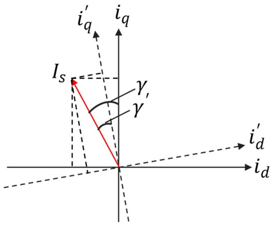
Figure 1.
Influence of positioning error of rotating coordinate system.
The actual current is obtained as
where is the current command amplitude of the stator.
Substitute (3) into (4) and define as (5) and satisfy .
The partial derivative of (5) can be derived as
Then define the function of as
where the coefficients satisfy
Then one can conclude
The analysis reveals that the rate of change in the output torque of the PMSM is contingent on the current command angle, exhibiting a monotonically increasing trend within the interval (0, 0.5π). Notably, as the motor enters the deep flux weakening zone, the sensitivity to the error in parameter becomes more pronounced. Consequently, it becomes imperative to rectify the positioning error of the space vector [15,38,39,40].
Moreover, the Hall sensor and the conditioning circuit introduce a phase lag between the sampled current and the actual current. Figure 2 illustrates the presence of high-frequency switching signals in the sampled current. Therefore, it is crucial to judiciously configure the sampling delay to accurately capture the fundamental signal of the actual current [12,41].
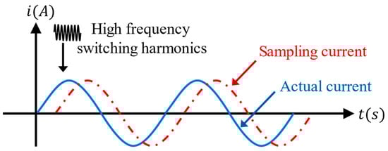
Figure 2.
Actual current and sampled current.
Simultaneously, the calculation time of the digital signal processing (DSP) controllers causes a delay in updating the pulse width modulation (PWM) waveform, trailing behind the actual time required for a sampling cycle, as illustrated in Figure 3. An approximate equivalent approach is to set the sampling and control delay at , where represents the system sampling period. Inaccuracies in the phase and amplitude of the output voltage necessitate dynamic compensation [42].
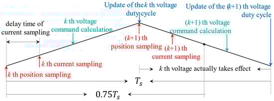
Figure 3.
PWM control timing.
2.3. Error of Motor Loss Model
In addition to ensuring the accuracy of active power calculation during torque estimation using power analysis, the impact of various motor losses, comprising copper loss, iron loss, stray loss, and wind friction loss, must be considered. Beyond the copper loss induced by the fundamental current, the skin effect and proximity effect arising from high-frequency AC signal injection contribute additional copper losses, posing challenges for precise analysis and calculation. The iron loss, a crucial component in the motor’s total loss, becomes particularly significant at high magnetic density and frequency, exerting a substantial influence on motor control performance. The fundamental iron loss, resulting from the alternating main flux, encompasses hysteresis loss and eddy current loss, and can be approximately calculated as
where and are hysteresis and eddy current coefficients of the PMSM.
When considering the additional loss caused by the leakage magnetic field, the iron loss can be roughly calculated as
where , , , and are the additional loss coefficient, frequency, magnetic density amplitude, and constant coefficient, respectively. The above coefficient values in the theoretical model are generally obtained using the least squares method fitting according to the test curve of loss magnetic density provided by the silicon steel sheet manufacturer, and therefore the iron loss can only be roughly calculated. Meanwhile, process operations such as stamping, stacking, and heating in the manufacturing process will also affect the electromagnetic performance of the material, which is difficult to quantify in the loss model. In addition to copper and iron loss, some active power will also be converted into spurious losses and wind friction loss, which are also difficult to calculate accurately due to the uncertainty of parameters and models.
3. Torque Estimation and Multi-Closed-Loop Control Strategy
The current closed-loop control is simple, but it is an open-loop for torque that cannot suppress the disturbance of factors such as parameter error in FOC and motor loss changes on the accuracy of the output torque. To ensure the actual accuracy of the output torque under this condition, this paper proposes a novel torque estimation scheme based on the calibration experiments from the perspective of power analysis and designs a multi-closed-loop control strategy on this basis to realize the simultaneous correction of angle and amplitude of the preset current command.
3.1. Torque Estimation Scheme
The active power injected into the motor from the inverter is
Part of the active power is converted into mechanical power to generate output torque and the rest is converted into various motor losses .
where equals the sum of copper loss , iron loss , stray loss , and wind friction loss .
Considering the temperature variation, the DC resistance of the stator windings can be represented as
where is the rated resistance under the rated temperature , is the constant related to the material and , and is the actual temperature of the resistance.
Then the copper loss can be obtained as
The output torque can be estimated by (19).
where is the speed.
To overcome the calculation inaccuracy of iron loss, stray loss, the wind friction loss model, and the influence of factors such as the production process and temperature fluctuation on the accuracy of motor torque estimation, this paper introduces a new torque estimation scheme as shown in Figure 4.
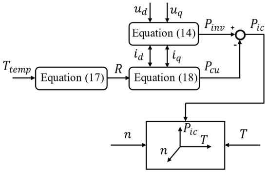
Figure 4.
Torque estimation.
Based on the temperature signals and electrical signals from the sensors, the active power and copper loss are calculated in (14), (17), and (18), and the parameter is introduced as
Then, the mapping between the parameter and the actual torque at different motor speeds can be obtained based on the motor calibration experiments, which are established in engineering and realize the estimation of the actual torque under any working condition.
Although temperature fluctuations will cause changes in the permanent magnet flux linkage, dq-axis inductance, and armature winding resistance, which will affect the output active power and copper loss, the calculation of active power only depends on the current vector, voltage vector, and positioning accuracy. That is, the influence of temperature on the actual active power is reflected indirectly through the calculation processing by using real-time signals collected from sensors. The calculation of fundamental copper loss also only depends on the actual detected current vector and temperature value; that is, the influence of temperature has been considered, so this scheme avoids not only the complex and inaccurate loss calculation but also the effect of temperature on torque estimation. Under fixed working conditions, the iron loss is mainly affected by the space flux linkage according to Equation (12). Under the condition that and remain unchanged, the consistency of the fundamental wave iron loss of each working condition in mass production can be guaranteed by introducing the voltage closed-loop mentioned later to adjust the actual output voltage . This operation makes the calibration data from to of a single motor at different speeds more universal. The utilization of LUTs proves to be more resource-efficient compared to many online solving solutions. However, to ensure the precision of practical torque observations, it is imperative to guarantee an appropriate data resolution during offline calibration processes.
3.2. Multi-Closed-Loop Control Strategy
The parameter error in FOC, temperature fluctuation, and the inconsistency of motor products caused by multiple factors will affect the accurate control of the actual torque. It is rather difficult for the current closed-loop control strategy to suppress the influence of the above factors on accuracy. Thereby, a multi-closed-loop control strategy for PMSMs is proposed as shown in Figure 5. The strategy is mainly composed of three modules: the LUT module, the detection and adjustment module, and the motor and drive module.
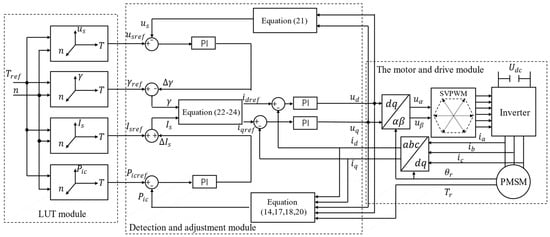
Figure 5.
Multiple-closed-loop control strategy.
For the load request torque at the current speed , the preset current command in the form of amplitude and angle is obtained through the LUT module, whose relative variables include the amplitude , the angle , the reference voltage under the corresponding working condition, and the reference power coefficient .
The inner loop is used for the accurate dynamic regulation of the current. The measured three-phase current from sensors is transformed into the dq coordinate system by Clark-Park. Then the feedback values of the dq-axis currents and are obtained, which are respectively compared with the reference values and to obtain the control voltage vectors and by the current PI controller. The outer loop uses power and voltage to control the amplitude and angle of the preset current command, respectively, and then it calculates the power coefficient and voltage amplitude feedback values according to the actual dq-axis current, voltage vector, and the sampled value of the motor temperature, where is calculated as
The power loop compares the reference value with the feedback value to obtain the amplitude compensation for the preset current through the power PI controller, and then the voltage loop compares the reference value with the feedback value to obtain the angle compensation for the preset current through the voltage PI controller. The reference values and for the dq-axis current of the inner loop are calculated as
The voltage vectors and in the two-phase static coordinate system are obtained by the inverse Park transformation, and then the switching state of the power switching device of the inverter is controlled by space vector pulse width modulation (SVPWM) to drive the motor.
Figure 6 discusses the changes in the output torque of the PMSM with the FOC-related error of the current angle parameter , the motor temperature rise, and the adjustment process of the multi-closed-loop control strategy for the current command. In the optimal current command trajectory obtained under the ideal rotating coordinate frame, the command corresponds to the ideal output torque , and the command just satisfies the voltage curve limit at this speed. However, due to the error of , the actual dq-axis current will deviate from the ideal current command in the real rotating coordinate frame as in Figure 6a. If the d-axis deviates to , the corresponding current vector no longer reaches the inverter voltage limit at this speed, and the actual output torque is . The outer voltage loop of the control strategy detects the deviation between the voltage reference and the voltage feedback , and the PI controller outputs the compensating angle for the preset current command angle to correct to to satisfy the voltage limit of the current command again.
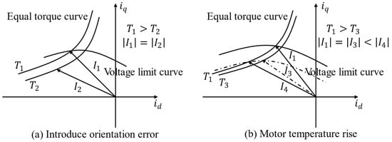
Figure 6.
Variation of torque and adjustment of the current command.
If the error of is eliminated under the same working conditions, the temperature increase of the motor will change the voltage limit curve at this speed, as shown in Figure 6b. Now the current command exceeds the voltage limit of the inverter, so the flux weakening angle should be increased and correct to . However, points to the equal torque curve corresponding to , and the actual output torque decreases. Therefore, to output the expected torque, the current command must be compensated for the amplitude and angle of the preset current command along the real voltage limit curve until the actual current is corrected to . The power loop and the voltage loop compensate for the amplitude and the angle of the current command, respectively.
4. Experiment Validation
The main hardware facilities involved in the experimental platform include a PMSM, dynamometer, motor controller, central PC workstation, and a water-cooling circulation system, among others, as illustrated in Figure 7.
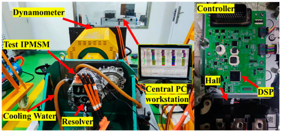
Figure 7.
Testing rig.
The PMSM used in the experiment is an embedded type, and its specific parameters are detailed in Table 1. The motor serves as the prime mover, interacting with the dynamometer. A torque sensor is strategically positioned to provide real-time torque output during the experiment. The experimental motor employs a water-cooling circulation system for effective heat dissipation, with the cooling temperature of the circulating fluid being adjustable. Additionally, an internal temperature sensor is placed within the permanent magnet synchronous motor for real-time monitoring of its internal temperature. At the motor’s end, a rotary transformer is installed to facilitate real-time detection of rotor position and speed. Three-phase current sampling is achieved using Hall sensors.

Table 1.
Parameters of the PMSM.
A control system based on NXP MPC5744P was built. The chip operates at a frequency of 200 MHz. To ensure optimal dynamic performance, the current inner loop was set at a frequency of 20,000 Hz, while the power outer loop and voltage outer loop were set at 2000 Hz. The controller communicates via Controller Area Network (CAN) with the upper computer (CANTest/CANPro) in the central PC workstation, allowing real-time monitoring of the motor’s operational status. Moreover, the main console has the capability to send instructions at any time, facilitating the switching of motor control modes. This configuration enables the controller to maintain real-time control and monitoring of the motor, offering flexibility in operational modes through external commands from the upper computer.
4.1. The Effect of Motor Loss Error
The torque observation based on the power calculation method [35] using loss models is hindered by parameter uncertainties, making it challenging to achieve precise measurements. To illustrate the impact of the model and parameter uncertainties, two sets of comparative experiments were conducted.
In the initial operating state, the prescribed speed and output torque were set at (2000 rpm, 47.8 Nm) and (3000 rpm, 97.3 Nm), respectively. During these two operational points, the control impact of both the power and voltage loops was disabled, leaving the current loop solely responsible for control. After a stable operation period of 20 s, a command was transmitted from the console to activate the multi-closed-loop system.
Figure 8 depicts the experimental results at 2000 rpm. The designated mechanical power for this condition is 10.0112 kW, yet the model-calculated actual power is 8.861 kW, falling short of the given value. Upon enabling the multi-closed-loop, adjustments to the dq current commands led to an unexpected torque increase from the preset 47.8 Nm to 53.3 Nm, accompanied by unnecessary compensation.
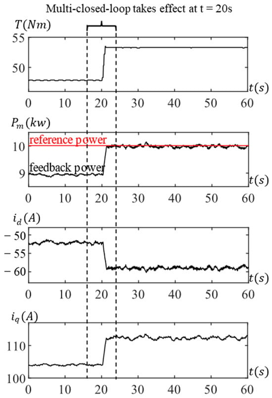
Figure 8.
Testing results at 2000 rpm with motor loss error.
Similarly, Figure 9 illustrates the experimental outcomes at 3000 rpm. The prescribed mechanical power for this condition is 30.5677 kW, while the model-calculated power is 28.903 kW. Activating the torque closed-loop results in current adjustments, causing the torque to deviate from the expected value, jumping from the preset 97.3 Nm to 102.4 Nm.
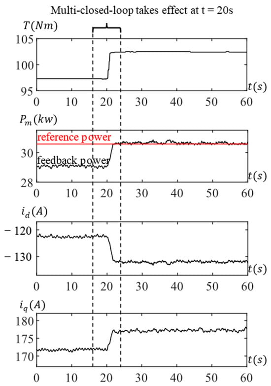
Figure 9.
Testing results at 3000 rpm with motor loss error.
These experimental findings highlight the inaccuracies in the loss model calculations, underscoring the significant impact of calculation errors on the precision of actual torque control. To ascertain that the control strategy proposed in this paper achieves heightened accuracy and effectively mitigates the influence of Field-Oriented Control (FOC)-related parameter errors and motor temperature fluctuations on torque accuracy, corresponding experiments were conducted under diverse motor working conditions.
4.2. Precision Comparison of MTPA Region
In the MTPA operating range of the PMSM, two specific operating points were chosen for experimental validation. The designated speed and output torque for the initial operating state were set at (2000 rpm, 47.8 Nm) and (3000 rpm, 97.3 Nm), respectively. During these two operational points, the initial state disengages the control impact of the power loop and the voltage loop, relying solely on the current loop for control. After 10 s of stable operation, a command is issued from the console to introduce an error of 12° to .
Figure 10 displays the experimental results at 2000 rpm. At t = 10 s, the actual current command experiences a significant deviation in the rotating coordinate frame due to the introduction of the angle , which increases from 26.6° to 38.6°. Although the amplitude remains relatively stable, the output torque decreases from 47.8 Nm to 45.7 Nm. Referring to Figure 6a facilitates a clear understanding of this variation process, where the actual current vector is consistently biased towards the negative d-axis with an equal amplitude.
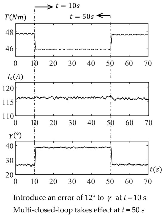
Figure 10.
Test at 2000 rpm with voltage control.
At t = 50 s, the console issues a control command to enable the multi-closed-loop. As illustrated in the principle shown in Figure 5, due to the deviation of the current vector, the voltage loop detects a deviation in the feedback voltage, swiftly compensating the actual current command angle back to its initial vicinity and restoring the actual output torque.
Similarly, the experimental results for the operating points at 3000 rpm are depicted in Figure 11. Likewise, at t = 10 s, a positioning error is introduced, causing the current angle to increase from 35.2° to 47.2° and the output torque to drop from 97.3 Nm to 91.9 Nm. By t = 90 s, due to the compensation of the voltage loop, the actual current command angle and output torque are rapidly recovered.
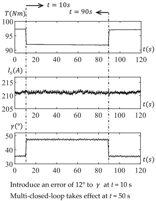
Figure 11.
Test at 3000 rpm with voltage control.
In Table 2, a comparison of actual torque control errors between the torque control method based on the loss model and the multi-closed-loop proposed in this paper is presented under MTPA operating conditions. The experimental results demonstrate that the torque control precision of the multi-closed-loop strategy is significantly superior to that of the loss model method. Furthermore, these comparative experiments indicate that the proposed approach is effective in mitigating the impact of dq coordinate system position errors on precision.
Table 2.
Comparative analysis of torque control errors in the MTPA.
4.3. Precision Comparison of FW Region
In the flux-weakening operation range of the PMSM, two distinct operating points were selected for experimental validation. The specified speed and load torque for the initial state were set at (6000 rpm, 97.3 Nm) and (7000 rpm, 76.7 Nm), respectively. Similar to the MTPA experiments, the initial states of both operating points deactivate the effects of the power loop and the voltage loop, relying solely on the current loop for control. However, in this set of experiments, the motor’s running time was extended to ensure a broader temperature rise span, emphasizing the impact of temperature on motor torque and the control strategy’s ability to mitigate temperature-induced effects.
The experimental outcomes at 6000 rpm are illustrated in Figure 12. At t = 10 s, a command is issued from the console to introduce a 6° error to . Subsequently, the actual current command deviates, with increasing from 48.6° to 54.6°, and the actual output torque decreases from 97.3 Nm to 89.7 Nm. By t = 30 s, a command is given to simultaneously enable the power loop and the voltage loop, leading to a swift recovery of the actual current command angle and output torque. Although both outer loops are activated simultaneously, the stable torque recovery is primarily attributed to the angle compensation of the voltage loop, as the temperature change is not prominent during this process.
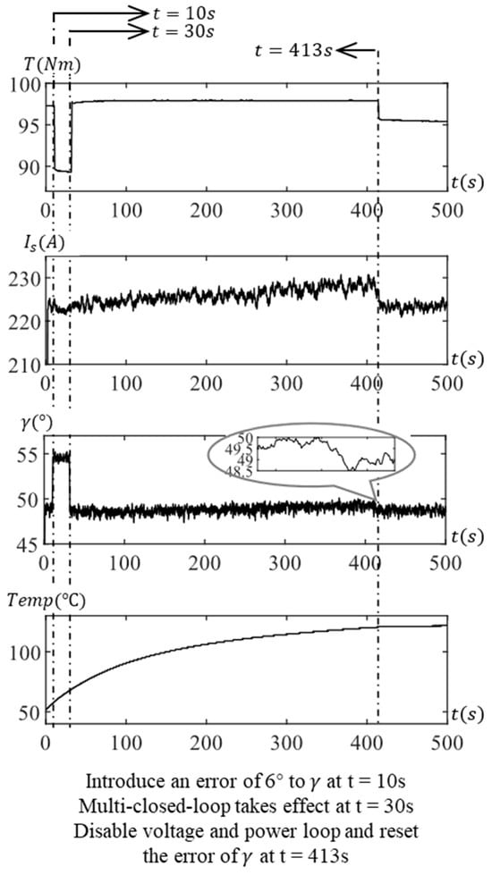
Figure 12.
Test at 6000 rpm with power and voltage control.
After operating in this state for a period, the motor temperature increases, leading to an elevation in the resistance of the stator winding and a weakening of the flux linkage of the permanent magnet in the hotter state. Without compensation, the actual output torque is inevitably reduced. At t = 413 s, the temperature rises from 52 °C to 121 °C. As illustrated in Figure 5, both the power and voltage loops detect feedback errors. Due to the concurrent regulation of the power loop and the voltage loop, the current command is effectively compensated based on the initial operating state value. As a result, is adjusted from 222.7 A to 229.0 A, is modified from 48.8° to 49.8°, and the actual output torque remains close to the initial value during the temperature rise process. Therefore, the control strategy’s effectiveness in maintaining output torque accuracy is validated under the influence of error and temperature fluctuations. At t = 413 s, the console issues a command to disable the power loop and voltage loop and clear the error. The current loop control alone proves insufficient to mitigate the output torque drop caused by the temperature rise. Consequently, the actual output torque decreases from 97.3 Nm to 95.5 Nm, with the output torque continuing to decline as the temperature rises.
The experimental results at 7000 rpm are presented in Figure 13. Similarly, at t = 10 s, due to the introduced error, the actual increased from 52.0° to 58.0°, and the actual output torque dropped from 76.7 Nm to 68.0 Nm. By t = 30 s, the power loop and voltage loop were simultaneously enabled, leading to a swift recovery of the actual current command angle and output torque. This operational state was sustained for an extended duration until t = 862 s, during which the temperature rose from 31.1 °C to 110.0 °C. The power loop compensated for the current amplitude from the initial 192.5 A to 198.4 A, and the voltage loop adjusted the current angle from 52.0° to 53.2°, with the actual output torque remaining close to the initial value. After disabling the power loop and voltage loop and clearing the positioning error, the output torque decreased from 76.9 Nm to 75.0 Nm.
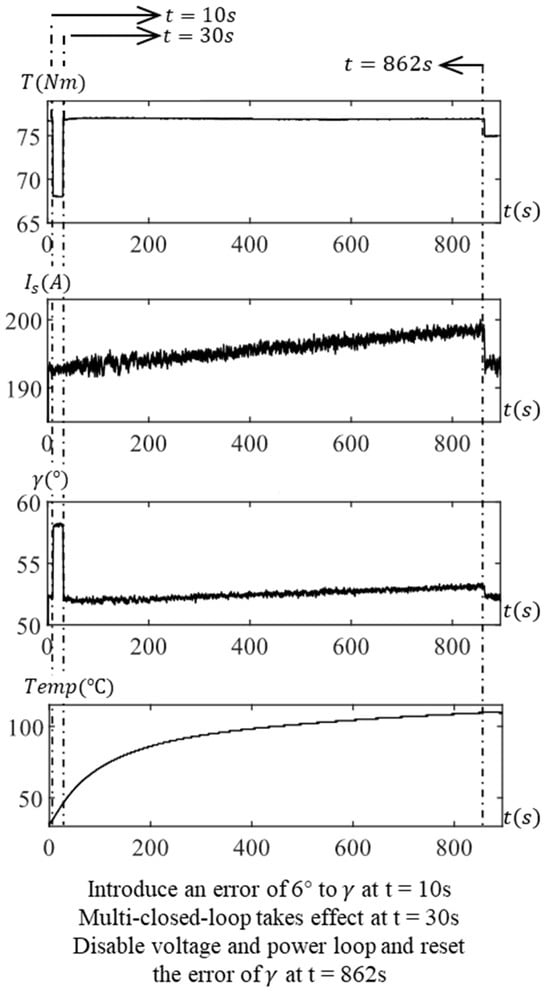
Figure 13.
Test at 7000 rpm with power and voltage control.
In the flux-weakening region, a comparison of torque control errors between the open-loop torque control method based on current LUT and the multi-closed-loop method is presented in Table 3, considering the introduction of dq coordinate system position deviation and temperature fluctuations. The experimental results demonstrate that the multi-closed-loop strategy exhibits higher precision. Its ability to dynamically adjust current command amplitude and angle based on the actual motor operating state effectively mitigates the impact of the mentioned factors on precision.
Table 3.
Comparative analysis of torque control errors in the FW.
4.4. Feasibility and Effectiveness for Wide Operating Range and Complex Conditions
To validate the accuracy and adaptability of the proposed torque estimation scheme across a broad spectrum of motor operations, including its resilience to motor temperature fluctuations, flux linkage changes, and non-uniform factors in large-scale production, comparative experiments were conducted. Throughout these experiments, a PMSM with a cooling water temperature of 25 °C and a positioning error of 0° served as the reference for measuring its torque map across the entire speed range, providing the torque reference for the proposed torque estimation scheme.
In the initial comparative experiment, the same motor was subjected to a temperature increase to 45 °C, and a torque map experiment was conducted to measure the comparatively estimated torque . The estimated torque error percentage was represented as:
In the second experiment, multiple PMSMs from the same batch were employed, with identical water temperature and γ error settings as the reference motor, to conduct torque map experiments. Torque error percentages were calculated under each working condition. The third experiment utilized the reference motor, introducing a error of 3° to conduct corresponding experiments and calculate the error percentage.
The maximum estimated torque error percentages at each speed of the three groups of comparative experiments are counted in Figure 14. The results of the comparative experiments show that the proposed torque estimation scheme can ensure high accuracy under the disturbance of various factors and in a wide operating range, thus ensuring the feasibility and effectiveness of the proposed control strategy.

Figure 14.
Error of torque estimation.
5. Conclusions
In the presence of non-ideal factors such as temperature fluctuations and dq coordinate system position errors, the output electromagnetic torque of a PMSM undergoes variations, thereby influencing the overall system performance. Although open-loop torque control based on current lookup tables exhibits commendable dynamic response capabilities, it struggles to mitigate the impact of the aforementioned factors. This study conducts offline experiments employing a data-driven approach to map the nonlinear relationships among power, fundamental copper losses, and torque. In comparison to the theoretical power analysis method, this data-driven approach effectively circumvents the influence of model and parameter uncertainties. It achieves dynamic adjustments of both angle and amplitude for preset current commands, enhancing the consistency of torque output. Undoubtedly, creating LUTs involves laborious calibration experiments and considerable storage resource usage—an essential consideration for implementing this method. Future work will prioritize optimization in this regard and delve into exploration of the robust performance of this complex nonlinear system.
Author Contributions
Methodology, F.J. and R.C.; Data collection and analysis, F.J. and Q.S.; Validation, F.J., Q.S. and R.C.; Investigation, F.J.; Resources, F.J.; Supervision, Y.L. All authors have read and agreed to the published version of the manuscript.
Funding
This research was funded by the Zhejiang Province Key R&D Program Project under Grant 2023C01132.
Data Availability Statement
Data are contained within the article.
Conflicts of Interest
Author Ran Cao was employed by the company Zhejiang Leapmotor Technology Co., Ltd. The remaining authors declare that the research was conducted in the absence of any commercial or financial relationships that could be construed as a potential conflict of interest.
References
- Khayamy, M.; Chaoui, H. Current Sensorless MTPA Operation of Interior PMSM Drives for Vehicular Applications. IEEE Trans. Veh. Technol. 2018, 67, 6872–6881. [Google Scholar] [CrossRef]
- Shi, Z.; Sun, X.; Cai, Y. Torque Analysis and Dynamic Performance Improvement of a PMSM for EVs by Skew Angle Optimization. IEEE Trans. Appl. Supercond. 2019, 29, 1–5. [Google Scholar] [CrossRef]
- Meesala RE, K.; Athikkal, S.; Pradhan, P. Modified Direct Torque Control of PMSM Drive for Electric Vehicle Application. In Proceedings of the IEEE Madras Section Conference (MASCON), Chennai, India, 27–28 August 2021; pp. 1–5. [Google Scholar]
- Chinthala, A.; Vuddanti, S. Performance Analysis of Induction Motor and PMSM for Electrical Vehicle Traction Application. In Proceedings of the 2022 IEEE International Conference on Distributed Computing and Electrical Circuits and Electronics (ICDCECE), Ballari, India, 23–24 April 2022; pp. 1–6. [Google Scholar]
- Ewert, P.; Orlowska-Kowalska, T.; Jankowska, K. Effectiveness analysis of PMSM motor rolling bearing fault detectors based on vibration analysis and shallow neural networks. Energies 2021, 14, 712. [Google Scholar] [CrossRef]
- König, P.; Sharma, D.; Konda, K.R. Comprehensive Review on Cooling of Permanent Magnet Synchronous Motors and Their Qualitative Assessment for Aerospace Applications. Energies 2023, 16, 7524. [Google Scholar] [CrossRef]
- Stender, M.; Wallscheid, O.; Böcker, J. Accurate Torque Control for Induction Motors by Utilizing a Globally Optimized Flux Observer. IEEE Trans. Power Electron. 2021, 36, 13261–13274. [Google Scholar] [CrossRef]
- Chen, S.; Hao, X.; Gao, C. A High Performance Control Method for IPMSM Based on Lookup Tables Considering the System Nonlinearalities. In Proceedings of the 2023 IEEE 6th International Electrical and Energy Conference (CIEEC), Hefei, China, 12–14 May 2023; pp. 710–715. [Google Scholar]
- Kim, D.-Y.; Lee, J.-H. Low Cost Simple Look-Up Table-Based PMSM Drive Considering DC-Link Voltage Variation. Energies 2020, 13, 3904. [Google Scholar] [CrossRef]
- Kim, D.-Y.; Lee, J.-H. Compensation of Interpolation Error for Look-Up Table-Based PMSM Control Method in Maximum Power Control. Energies 2021, 14, 5526. [Google Scholar] [CrossRef]
- Cao, R.; Hu, D.; Cao, Y. Practical Compensation Strategy for Accurate Torque Control in Mass-Produced High-speed Traction IPM E-Drives. In Proceedings of the 2021 IEEE Energy Conversion Congress and Exposition (ECCE), Vancouver, BC, Canada, 10–14 October 2021; pp. 4654–4660. [Google Scholar]
- Wang, W.; Yan, H.; Wang, X. Analysis and Compensation of Sampling-Delay Error in Single Current Sensor Method for PMSM Drives. IEEE Trans. Power Electron. 2022, 37, 5918–5927. [Google Scholar] [CrossRef]
- Li, P.; Liao, Y.; Lin, H. An Improved Three-Phase Current Reconstruction Strategy Using Single Current Sensor with Current Prediction. In Proceedings of the 2019 22nd International Conference on Electrical Machines and Systems (ICEMS), Harbin, China, 11–14 August 2019; pp. 1–5. [Google Scholar]
- Wu, Y.; Li, H.; Wang, L. Zero-Position Offset Calibration of PMSM Based on I/F Control Strategy and Slide Mode Observer for Electric Power Steering System. In Proceedings of the 2023 IEEE International Symposium on Sensorless Control for Electrical Drives (SLED), Seoul, Republic of Korea, 16–18 August 2023; pp. 1–6. [Google Scholar]
- Zossak, S.; Stulraiter, M.; Makys, P. Initial Position Detection of PMSM. In Proceedings of the 2018 IEEE 9th International Symposium on Sensorless Control for Electrical Drives (SLED), Helsinki, Finland, 13–14 September 2018; pp. 12–17. [Google Scholar]
- Singh, A.K.; Raja, R.; Sebastian, T. Effect of Position Measurement Delay on the Performance of PMSM Drive. In Proceedings of the 2018 IEEE Energy Conversion Congress and Exposition (ECCE), Portland, OR, USA, 23–27 September 2018; pp. 4622–4627. [Google Scholar]
- Kim, S.; Park, K.; Kang, D. High-Performance Permanent Magnet Synchronous Motor Control with Electrical Angle Delayed Component Compensation. IEEE Access 2023, 11, 129467–129478. [Google Scholar] [CrossRef]
- Moghadam, H.A.; Saeidi, M.; Vahedi, A. Position Sensor Error Analysis for PMa-SynR Motor Drive system. In Proceedings of the 2019 International Power System Conference (PSC), Tehran, Iran, 9–11 December 2019; pp. 100–105. [Google Scholar]
- Pramod, P.; Zhang, Z.; Namburi, K.M. Effects of Position Sensing Dynamics on Feedback Current Control of Permanent Magnet Synchronous Machines. In Proceedings of the 2018 IEEE Energy Conversion Congress and Exposition (ECCE), Portland, OR, USA, 23–27 September 2018; pp. 3436–3441. [Google Scholar]
- Cho, S.Y.; Shin, W.G.; Park, J.S. A Torque Compensation Control Scheme of PMSM Considering Wide Variation of Permanent Magnet Temperature. IEEE Trans. Magn. 2019, 55, 8200105. [Google Scholar] [CrossRef]
- Gao, L.; Xu, J.; Zheng, H. Impacts of Permanent Magnet Synchronous Machine under Different Rotor Temperature. In Proceedings of the 2018 IEEE Student Conference on Electric Machines and Systems, Huzhou, China, 14–16 December 2018; pp. 1–5. [Google Scholar]
- Laborda, D.F.; Reigosa, D.D.; Fernández, D. Magnet Temperature Estimation in Variable Leakage Flux Permanent Magnet Synchronous Machines Using the Magnet Flux Linkage. In Proceedings of the 2020 IEEE Energy Conversion Congress and Exposition (ECCE), Detroit, MI, USA, 11–15 October 2020; pp. 6111–6117. [Google Scholar]
- Dini, P.; Saponara, S. Review on Model Based Design of Advanced Control Algorithms for Cogging Torque Reduction in Power Drive Systems. Energies 2022, 15, 8990. [Google Scholar] [CrossRef]
- Pierpaolo, D.; Saponara, S. Control system design for cogging torque reduction based on sensor-less architecture. In Applications in Electronics Pervading Industry, Environment and Society: APPLEPIES 2019 7; Springer International Publishing: Cham, Switzerland, 2020; pp. 309–321. [Google Scholar]
- Dini, P.; Saponara, S. Design of an Observer-Based Architecture and Non-Linear Control Algorithm for Cogging Torque Reduction in Synchronous Motors. Energies 2020, 13, 2077. [Google Scholar] [CrossRef]
- Dini, P.; Saponara, S. Cogging Torque Reduction in Brushless Motors by a Nonlinear Control Technique. Energies 2019, 12, 2224. [Google Scholar] [CrossRef]
- Ning, B.; Cheng, S.; Qin, Y. Direct torque control of PMSM using sliding mode backstepping control with extended state observer. J. Vib. Control. 2018, 24, 694–707. [Google Scholar] [CrossRef]
- Li, X.; Xue, Z.; Yan, X. Low-complexity multivector-based model predictive torque control for PMSM with voltage preselection. IEEE Trans. Power Electron. 2021, 36, 11726–11738. [Google Scholar] [CrossRef]
- Zheng, W.; Geng, Q.; Xu, X. Predictive Torque Control of the Vehicle’s Permanent-Magnet Synchronous-Motor Model Based on Multi-Objective Sorting. Appl. Sci. 2023, 13, 11572. [Google Scholar] [CrossRef]
- Kakouche, K.; Rekioua, T.; Mezani, S. Model Predictive Direct Torque Control and Fuzzy Logic Energy Management for Multi Power Source Electric Vehicles. Sensors 2022, 22, 5669. [Google Scholar] [CrossRef]
- Yin, Y. Optimal Direct Instantaneous Torque Control for SRMs Using Advanced Sliding Mode Controller. Appl. Sci. 2022, 12, 12177. [Google Scholar] [CrossRef]
- Navardi, M.J.; Milimonfared, J.; Talebi, H.A. Torque and Flux Ripples Minimization of Permanent Magnet Synchronous Motor by a Predictive-Based Hybrid Direct Torque Control. IEEE J. Emerg. Sel. Top. Power Electron. 2018, 6, 1662–1670. [Google Scholar] [CrossRef]
- Bilal, A.; Waheed, A.; Shah, M.H. A Comparative Study of Machine Learning Algorithms for Controlling Torque of Permanent Magnet Synchronous Motors through a Closed Loop System. In Proceedings of the 2019 Second International Conference on Latest trends in Electrical Engineering and Computing Technologies (INTELLECT), Karachi, Pakistan, 13–14 November 2019; pp. 1–6. [Google Scholar]
- Liu, X.; Du, Y. Torque Control of Interior Permanent Magnet Synchronous Motor Based on Online Parameter Identification Using Sinusoidal Current Injection. IEEE Access 2022, 10, 40517–40524. [Google Scholar] [CrossRef]
- Dianov, A.; Tinazzi, F.; Calligaro, S. Review and Classification of MTPA Control Algorithms for Synchronous Motors. IEEE Trans. Power Electron. 2022, 37, 3990–4007. [Google Scholar] [CrossRef]
- Reigosa, D.; Kang, Y.G.; Martínez, M. SPMSMs Sensorless Torque Estimation Using High-Frequency Signal Injection. IEEE Trans. Ind. Appl. 2020, 56, 2700–2708. [Google Scholar] [CrossRef]
- Alonso, D.F.; Kang, Y.; Laborda, D.F. Permanent Magnet Synchronous Machine Torque Estimation Using Low Cost Hall-Effect Sensors. In Proceedings of the 2019 IEEE 10th International Symposium on Sensorless Control for Electrical Drives (SLED), Turin, Italy, 9–10 September 2019; pp. 1–6. [Google Scholar]
- Kuruppu, S.S. In-System Calibration of Position Sensor Offset in PMSM Drives. In Proceedings of the 2021 IEEE International Electric Machines & Drives Conference (IEMDC), Hartford, CT, USA, 17–20 May 2021; pp. 1–5. [Google Scholar]
- Kim, D.; Kim, J.; Lim, H. A Study on Accurate Initial Rotor Position Offset Detection for a Permanent Magnet Synchronous Motor Under a No-Load Condition. IEEE Access 2021, 9, 73662–73670. [Google Scholar] [CrossRef]
- Chen, Y.; Li, M.; Gao, Y.-W. A sliding mode speed and position observer for a surface-mounted PMSM. ISA Trans. 2019, 87, 17–27. [Google Scholar] [CrossRef]
- Ray, G.; Acosta, M.; Kuruppu, S. Influence of Asymmetric Sampling Delay on PMSM FOC Drives with Varying Rotor Position. In Proceedings of the 2022 IEEE Transportation Electrification Conference & Expo (ITEC), Anaheim, CA, USA, 15–17 June 2022; pp. 1259–1265. [Google Scholar]
- Lv, W.; Huang, K.; Wu, H. A Dynamic Compensation Method for Time Delay Effects of High-Speed PMSM Sensorless Digital Drive System. In Proceedings of the 2019 22nd International Conference on Electrical Machines and Systems (ICEMS), Harbin, China, 11–14 August 2019; pp. 1–5. [Google Scholar]
Disclaimer/Publisher’s Note: The statements, opinions and data contained in all publications are solely those of the individual author(s) and contributor(s) and not of MDPI and/or the editor(s). MDPI and/or the editor(s) disclaim responsibility for any injury to people or property resulting from any ideas, methods, instructions or products referred to in the content. |
© 2023 by the authors. Licensee MDPI, Basel, Switzerland. This article is an open access article distributed under the terms and conditions of the Creative Commons Attribution (CC BY) license (https://creativecommons.org/licenses/by/4.0/).