Abstract
High-performance overmodulation strategies for voltage source inverters (VSIs) can further broaden the operation range of machines. Among them, Space Vector Pulse Width Modulation (SVPWM) is worth researching as it performs well in digital implementation. This paper presents a detailed comparison of various SVPWM overmodulation strategies and analysis of their performance. It firstly briefly elaborates fundamental laws of two subspaces of five-phase VSIs. Then, it focuses on several overmodulation strategies. Their corresponding basic principles and main characteristics are researched, and conclusions are given. In addition, differences and relationships between them are proved and summarized. Lastly, comparative simulations and experiments were carried out and verify that in the overmodulation region, the output voltage distortion degree increases with the increase in modulation ratio, and strategies with more control degrees of freedom (CDFs) are capable of better controlling the third harmonic subspace, which means that higher-quality output voltage waveforms would be obtained.
1. Introduction
With the development of power electronics technology and control theory, research on multi-phase machine systems is no longer limited by the three-phase power supply. Compared with conventional three-phase machine systems, multi-phase machine systems possess smaller torque ripple, higher power density, stronger fault tolerance capability and so on [1,2,3,4], which help them attract more attention in the fields like electric vehicles, electric ships and electric aircrafts, where high power output and reliability are normally required [5,6,7,8].
Multi-phase machine systems usually adopt multi-phase VSIs to supply electricity [2]. Among all the research on high-performance modulation technology of VSIs, SVPWM attracts much attention because of its superiority in digital implementation [9,10,11]. Given the developing trend of multi-phase machine systems, five-phase SVPWM strategies were the focus of this paper [12,13,14,15,16].
Five-phase SVPWM can be divided into linear and nonlinear modulation regions across the entire modulation range [14,17]. In SVPWM, when the reference voltage vectors exceed the linear modulation region, the conventional SVPWM method is no longer applicable. This region is referred to as the overmodulation region, where new control methods, known as overmodulation algorithms, are required to modulate the inverter. In the overmodulation region, the output voltage is higher, thus broadening the operating range of machines through increasing the dc bus voltage utilization (DBVU) without reducing the output torque. For example, when a permanent magnet synchronous machine runs at high speed [18,19,20,21], overmodulation strategies are needed to strengthen its torque output capability and broaden the speed range to improve the system performance. However, overmodulation strategies would introduce a certain amount of harmonic content. The harmonic has some effects on motor performance, such as torque capability, core loss and power factor [22]. Overmodulation strategies are worth deeper exploration as a means of optimizing the performance of multi-phase machine systems to minimize the negative effects of harmonic content on the systems.
Much research has recently been conducted on five-phase SVPWM. According to specific selections of basic voltage vectors during the process, current research can be roughly categorized into three types: the Nearest Two Vectors SVPWM (NTV-SVPWM) method, the Nearest Four Vectors SVPWM (NFV-SVPWM) method and the synthesized vector SVPWM (SV-SVPWM) method. Focusing on the five-phase machine systems, ref. [23] developed the traditional three-phase SVPWM strategy into a five-phase VSI and proposes a five-phase SVPWM strategy based on two large vectors which are adjacent to the reference voltage vectors. This strategy is simple and can be implemented with a high DBVU and low power switch loss, though it results in much harmonic content in the output voltage and adds the stator loss of machines at the same time [15,24]. Aiming at eliminating the deficiency of the NTV-SVPWM method, refs. [25,26,27] propose the NFV-SVPWM method using four basic vectors. This method increases the output voltage in the overmodulation range but involves much computation and has difficulty in digital applications. To overcome the above disadvantages, refs. [16,28] optimized the NFV-SVPWM method to obtain the SV-SVPWM method, which successfully simplifies the calculation and decreases the harmonic content of output voltage in the meantime. Ref. [29] proposes a novel overmodulation strategy with more CDFs on the basis of NFV-SVPWM, realizing the synchronous control of two subspaces.
To better present the development of five-phase SVPWM strategies and determine their relationships, this paper compares various overmodulation strategies, and their performance is also presented. At first, the principles of each strategy are analyzed. Subsequently, detailed comparisons are presented, focusing on key benchmarks essential for assessing their effectiveness. These benchmarks include: (1) the feasibility of digital implementation and computational complexity for each strategy; (2) the maximum nonlinear modulation ratio achieved by each strategy, (3) the amount of third harmonic content in the output voltage and (4) the distortion degree of the output voltage for each strategy. The aim is to provide references for deep research and wide applications of overmodulation technology in multi-phase machine systems. With the help of simulations, the harmonic content of each overmodulation strategy at different modulation ratios was determined, and the distortion degree of the output voltage under the same circumstances for all the strategies was also compared. Finally, relevant experimental results verify the above results in particular.
2. Analysis of Space Voltage Vectors of Five-Phase Inverter
In Figure 1, the topology of the five-phase inverter employs a full-bridge structure, with a DC bus voltage denoted by . The a-e represents the five bridge arms of the five-phase inverter. Each bridge arm consists of two power transistors, with the switching operations controlled by modulation signals.
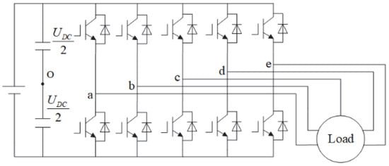
Figure 1.
Topology of a five-phase inverter.
Based on the space decoupling theory [30,31,32,33], an n-phase system can be decomposed into two-dimensional planes (n is an odd number) by extended Park transform, and these planes are orthogonal to each other. Both the fundamental wave and harmonic wave in the N-phase system are projected into the corresponding two-dimensional plane, and the last row of the Park transformation matrix corresponds to the zero-sequence plane. In the star-connected system, the zero-sequence plane does not participate in energy transfer, and the voltage vector in this plane will not affect the output characteristics of the system. Taking the five-phase system in this paper as an example, park transform is carried out based on the principle of voltage vector amplitude invariance. The first four rows of the matrix transform each physical quantity in the five-phase system into two mutually orthogonal planes, namely, the two-dimensional orthogonal subspaces and the zero-sequence subspace.
The corresponding relationship of amplitudes and phases for three kinds of vectors formed by different states of switches in two subspaces is exhibited in Table 1.

Table 1.
Relationship of 3 kinds of voltage vectors in two subspaces.
In the five-phase motor model, the increase in the number of phases results in the generation of the third harmonic subspace, with the basic voltage vector count also increasing to 32. Consequently, in five-phase SVPWM, there are more options available for selecting basic vectors to synthesize the reference voltage vector. Additionally, the presence of the third harmonic subspace highlights the significance of addressing issues related to accompanying vectors within this subspace. Compared to three-phase systems, the complexity is significantly heightened.
Among all modulation schemes designed for five-phase motors, NTV-SVPWM, biggest-four-vector SVPWM (BFV-SVPWM) and NFV-SVPWM are three commonly used modulation techniques. NTV-SVPWM follows the traditional principle of overmodulation from three-phase SVPWM, with simple and understandable steps. However, it encounters issues with accompanying vectors in the third harmonic subspace, leading to a high level of harmonic content in the output voltage. On the other hand, BFV-SVPWM and NFV-SVPWM address the problems arising from NTV-SVPWM when applied to five-phase VSIs by improving the synthesis of target reference voltage vectors. They increase the count of basic vectors used for synthesizing the reference voltage vector to 4, thus addressing the harmonic content issue within the subspace. These modulation schemes are not entirely independent; they inherit and develop from each other in terms of principles and implementation methods. Their ultimate goal is to minimize the output voltage harmonic content while ensuring high DC voltage utilization.
3. Comparison of Overmodulation Strategies for Five-Phase SVPWM
This section will briefly analyze several SVPWM overmodulation strategies and present a four-degree-of-freedom (FDF) overmodulation strategy. Different synthesis processes of the reference voltage vectors are separately discussed based on the certain principle of each strategy. At the same time, a more comprehensive comparison is made among all these strategies from the perspectives of DBVU and the harmonic content of output voltage. Lastly, characteristics of each strategy are summarized and listed.
3.1. Nearest Two Vectors SVPWM (NTV-SVPWM, M1)
Inspired by three-phase SVPWM, NTV-SVPWM (M1) chooses two large vectors adjacent to the reference voltage vector as the basic vectors to synthesize [1,14]. Limited by only 2 CDFs, M1 does not actually possess a linear modulation area. Other overmodulation strategies enter the nonlinear regions when the modulation ratio m is over 1.05. Based on this, M1 is studied in detail with m over 1.05 for a more direct comparison with other strategies.
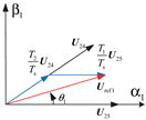
Take the reference voltage vector in the first sector as an example, shown in Figure 2. In Figure 2, the black arrow represents the basic voltage vector, the red arrow represents the reference voltage vector, and the blue arrow represents the projection of the reference voltage vector on the basic voltage vector. and are chosen as the basic vectors to synthesize the reference voltage vector. and represent the action time of and . Equation (1) can be obtained according to the voltage-second product balance principle:
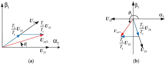
Figure 2.
Voltage vector synthesis diagram of NTV-SVPWM. (a) Vector synthesis in subspace. (b) Vector synthesis in subspace.
In (1), is the amplitude of the reference voltage vector; is the maximum amplitude of the basic voltage vector, which is 0.6472; is the DC bus voltage and is the period of pulse width modulation. For this strategy, the maximum modulation ratio is verified by (2).
When NTV-SVPWM is adopted, the maximum modulation ratio is 1.23. Compared with the three-phase SVPWM index of 1.15, the modulation index of five-phase SVPWM is obviously improved, and the bus voltage utilization rate is improved. The DBVU of NTV-SVPWM is high and can be simply realized. However, the reference voltage vector is synthesized in the subspace with the accompanying vector synchronously emerging in the subspace, making the harmonic content of the output phase voltage high. Therefore, a four-vector modulation strategy is put forward.
3.2. Nearest Four Vectors SVPWM (NFV-SVPWM, M2)
To deal with the deficiency of NTV-SVPWM, the four-vector PWM strategy is proposed [24], including two algorithms. The first involves the selection of the four largest vectors and the second the two largest and two medium vectors next to the reference vector to synthesize [34]. After centralizing PWM pulses of the first algorithm, it can be found that pulses are identical to those of the second, proving that these two algorithms share the same theory essence. Therefore, stress would be laid on the second algorithm and its improved strategy.
The second algorithm is named Nearest Four Vectors SVPWM (NFV-SVPWM, M2). The action time of basic vectors in M2 can be directly calculated through the matrix as (3) presents. This method has 4 CDFs but involves much calculation, which is not beneficial to digital implementation.
3.3. Synthesized Vector SVPWM (SV-SVPWM, M3)
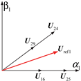
The synthesized vector SVPWM shown in Figure 3 simplifies the process of calculating the action time of basic vectors. Two basic vectors in the same direction are synthesized as a new basic vector called , namely, . During the process of synthesis, the number of CDFs is decreased from 4 to 3. In Figure 3, the black arrow represents the basic voltage vector, white represents the new voltage vector synthesized by two basic voltage vectors in the same direction, the red arrow represents the reference voltage vector, and the blue arrow represents the projection of the reference voltage vector on the two new voltage vectors.
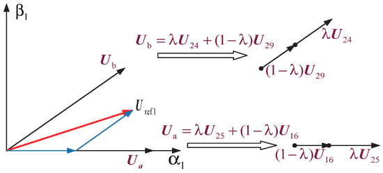
Figure 3.
New basic vector synthesis diagram of the improved NFV-SVPWM.
Based on Table 1, amplitudes of in the fundamental subspace and the third harmonic subspace are shown in (4).
When M3 works in the overmodulation region, it can be derived from (4) that the range of is from 0.618 to 1. At this time, the accompanying vector in the third subspace is no longer zero. The above analysis illustrates the fact that the requirement of a high DBVU would inevitably introduce the third harmonic. When , NFV-SVPWM transforms to NTV-SVPWM entirely.
Two different overmodulation algorithms of M3 will be introduced in the following (M3.1 and M3.2).
- 1.
- Overmodulation algorithm 1 of SV-SVPWM (M3.1)
Still taking the reference voltage vector in the first sector as an example, as shown in Figure 4. In Figure 4, the blue arrow has the same meaning as in Figure 3, and the red arrow represents two reference voltage vectors with different phase. The essential difference between M3.1 and M2 is that in M3.1, the amplitude of the newly synthesized basic vector is determined by the value of , which can then be used to deduce the value of , without considering the phase of .

Figure 4.
Reference voltage vector synthesis diagram of M3.1.
The value of can be obtained by , and the computation process is as follows:
According to (5), is used to represent , and then is substituted in (4). (6) is acquired as follows.
in (4) is substituted with (6), and the amplitude of the accompanying vector can be represented as (7).
The action time of synthesized vectors is displayed as (8).
Conclusions can be drawn that action time of each basic voltage vector has no connections with the amplitude of the reference voltage vector but is related to its phase.
- 2.
- Overmodulation algorithm 2 of SV-SVPWM (M3.2)
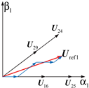
Compared with M3.1, overmodulation algorithm 2 of SV-SVPWM takes the phase varieties of reference voltage vectors into consideration. It has 3 CDFs like M3.1. The crucial step of modification is shown in Figure 5. When the initial value of is beyond the linear modulation range, certain adjustments would be made in , and it will be relocated on one side of a new decagon which is composed of 10 newly synthesized voltage vectors, making become the actual reference voltage vector. In Figure 5, the blue arrow has the same meaning as in Figure 3, the red solid arrow represents the reference voltage vector, and the red dashed arrow represents the adjusted actual reference voltage vector.

Figure 5.
Reference voltage vector synthesis diagram of M3.2.
Therefore, when the phase of is not , amplitudes of newly synthesized basic vectors, namely, and , can be reduced further when compared with M3.1. What is already known is that the amplitude of the accompanying vector in the third harmonic subspace is related to that of the newly synthesized basic vector; as a result, the former’s amplitude can be decreased as well, which would efficiently optimize the distortion degree of the output phase voltage. Specific computation steps are illustrated as follows.
Some transformations are applied to (9). can be presented with , and is substituted in (4). (10) is thus obtained.
Based on the above deductions, can be finally shown as (11).
The action time of newly synthesized basic vectors is finally obtained as (12) shows.
Comparing (7) and (11), it is clear that the amplitude of the accompanying vector of M3.2 is smaller than that of M3.1, which definitely suggests a lower amount of harmonic content in the output phase voltage of M3.2 in theory.
3.4. Research on FDF Overmodulation Strategy (M4)
It is clear that a five-phase VSI is a system with four CDFs, so two subspaces can be synchronously controlled only when the overmodulation strategy applied in this system is in possession of 4 CDFs.
The FDF-SVPWM overmodulation strategy researched in this section injects the third harmonic content into the subspace according to the modulation ratio set before to fully control this subspace. And the computation burden is efficiently relieved compared with M2. Take in the first vector as an example, which is shown as Figure 6. In Figure 6, the black arrow represents the basic voltage vector, the red arrow represents the reference voltage vector, and the blue arrow represents the projection of the reference voltage vector on the basic voltage vector.
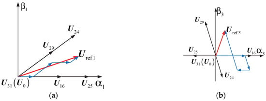
Figure 6.
Diagram of the first sector. (a) subspace. (b) subspace.
Suppose the ratio between the amplitude of the third harmonic and that of the fundamental wave is . Taking Figure 6 as the reference, (13) is finally obtained based on the voltage-second product balance theory.
In (13), represents the angle between and the axis. is the switching period. The result of (13) is as follows.
Since the sum of the action time of four basic voltage vectors should not exceed the switching period, (15) must be satisfied.
, , and are substituted in (15) with (14).
Suppose the denominator of right part of (16) is .
Then, the modulation ratio can be signified as (18).
Based on (17) and (18), (19) can be obtained:
Because m was defined previously and , the maximum and minimum values of (19) can be calculated. For a compromise of a high DBVU and a better quality of the output phase voltage, the average value of , rather than the extreme values, is chosen as the final third harmonic injection content. Equation (19) elaborates the relationship between the third harmonic content and the modulation ratio m. The third harmonic content is almost linear with m. The overmodulation range is divided into 3 regions, and some necessary linearization is performed to simplify the computation, and then (20) can be obtained:
According to (20), when the modulation ratio m is known in advance, the third harmonic content can then be determined, which makes the complete control of subspace feasible.
3.5. Comparison and Discussion
To be concluded, all the above overmodulation strategies are unique and linked with each other. NTV-SVPWM is developed from the conventional three-phase SVPWM and easy to be realized. The maximum overmodulation ratio of this strategy can reach 1.23, but it has only 2 CDF, which merely satisfies the amplitude requirement of output voltage in the fundamental subspace, without solving the accompanying vector problem in the third harmonic subspace. NFV-SVPWM selects four basic voltage vectors to synthesize and maintains the number of CDFs as 4, but it requires much computation and is not convenient for digital application. The improved NFV-SVPWM, namely, SV-SVPWM, selects two basic vectors which are in one direction to compose a new basic vector. This strategy shares a similar principle with NTV-SVPWM. As a result, it enjoys the advantages of lower harmonic content when compared to M1 and simplification in the computation if compared with M2. However, the previously defined modulation ratio m fixes the proportion between the action time of the large vector and medium vector, which inevitably decreases the CDFs and can no longer entirely control the third harmonic subspace.
Compared with the above strategies, the FDF overmodulation strategy actively obtains the relationship between the third harmonic content and the modulation ratio. Afterwards, it determines the third harmonic injection amount according to the defined m, keeping its number of CDFs as 4. As a result, M4 outputs a better phase voltage waveform with a lower amount of harmonic content. Consequently, the waveform distortion degree is smaller, reducing noise and the loss of multi-phase motors. All the above points are beneficial to a widespread application of multi-phase motors in scenarios where high power and excellent performance are necessary.
All the above comparisons are listed in Table 2. In Table 2, the black arrow represents the basic voltage vector, the red arrow represents the reference voltage vector, and the blue arrow represents the projection of the reference voltage vector on the basic voltage vector.

Table 2.
Comparison of various overmodulation strategies.
4. Simulation and Analysis
To further verify and compare the above mentioned five-phase SVPWM overmodulation strategies, simulations were conducted based on MATLAB 2021/Simulink. The DC bus voltage was set to 100 V and the switching frequency to 5 kHz to obtain waveforms at different modulation ratios.
Figure 7 shows the voltage vector trajectories of each algorithm in the subspace at 3 modulation ratios. The formula of the accompanying vector’s amplitudes is as follows.
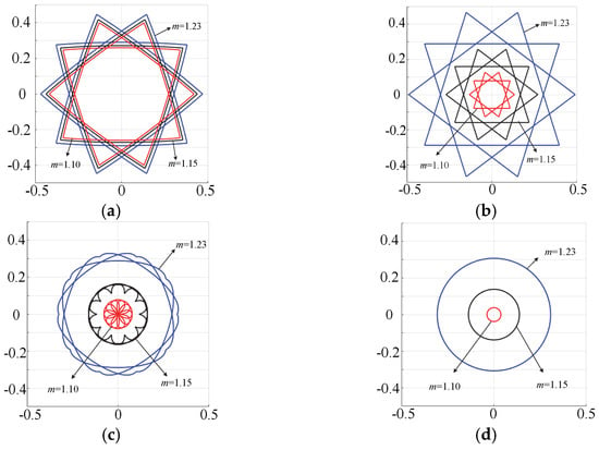
Figure 7.
Voltage vector trajectories of each overmodulation strategy in the subspace. (a) M1 (NTV-SVPWM). (b) M3.1 (algorithm 1 of the synthesized vector method). (c) M3.2 (algorithm 2 of the synthesized vector method). (d) M4 (FDF strategy).
It can be summarized from (21) that the distance between an arbitrary point in the trajectory and the coordinate origin is equal to the amplitude of this accompanying vector.
Figure 7 proves that with the increase in modulation ratio, amplitudes of accompanying vectors in every strategy increase accordingly. The shape of trajectories in M1 does not change. The amplitude in M1 is the largest because it has 2 CDFs.
Figure 7b,c display that shapes of trajectories in M3.1 are identical, while those of M3.2 are different. This can be attributed to the fact that the amplitude of the newly synthesized basic vector in M3.2 changes continuously with the change in the reference voltage vector’s phase. The amplitude of the accompanying vector in M3.2 is smaller than that of M3.1 but at the same time exceeds that of M4.
The amplitude of M4 shown in Figure 7d is a constant value, which makes the trajectory a circle. Compared with other 3 algorithms, M4 possesses 4 CDFs, so it can synchronously control the fundamental wave and third harmonic subspaces efficiently, which results in the smallest amplitude of the accompanying vector among all the strategies.
Figure 8 integrates vector trajectories of four strategies with the same modulation ratio in Figure 7 together for a clearer comparison. Simulations at 3 modulation ratios were carried out. It can be seen that the amplitude of the accompanying vector in M4 is the smallest. But this advantage is less dominant with the enhancement of m. When m is up to 1.23, the amplitude in M4 is almost the same as that of other 3 strategies. In contrasts with the irregular shapes of trajectories of other strategies; the shape of M4 is a circle, which shows that the amplitude in this strategy does not change when the phase of the reference voltage vector is altered.

Figure 8.
Accompanying vector trajectory comparisons of 4 strategies at different modulation ratios. (a) m = 1.1. (b) m = 1.15. (c) m = 1.23.
The steady state of the accompanying vector demonstrates that the harmonic content of the output voltage is more stable in M4. Even though the reference voltage vector falls in some special locations (like the boundaries of sectors), it will not cause points of inflection, which protrude outwards like other strategies, proving that the third harmonic subspace is controlled more successfully when M4 is working.
Figure 9 and Figure 10 show the output phase voltage waveforms, filtered waveforms, and low-frequency spectrum analysis of each strategy with 2 different modulation ratios.
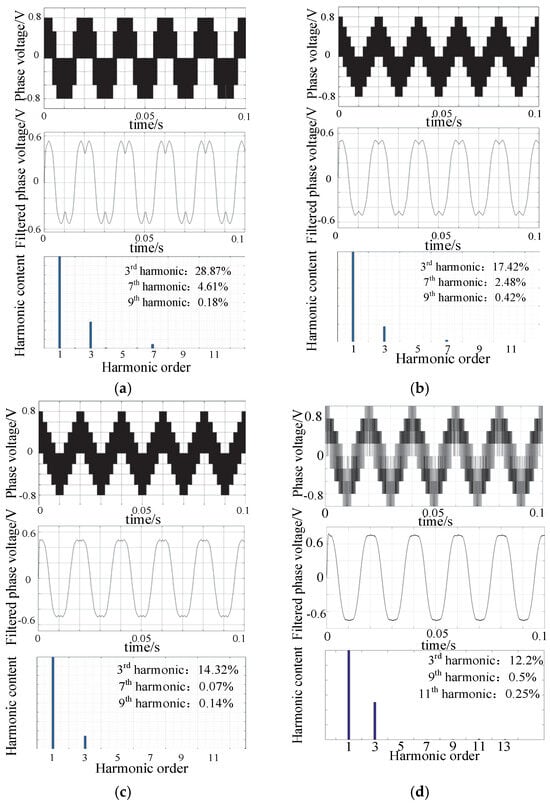
Figure 9.
Output phase voltage and its low-frequency spectrum analysis (m = 1.15). (a) M1. (b) M3.1. (c) M3.2. (d) M4.
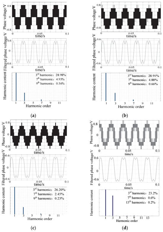
Figure 10.
Output phase voltage and its low-frequency spectrum analysis (m = 1.23). (a) M1. (b) M3.1. (c) M3.2. (d) M4.
It can be observed in Figure 9 and Figure 10 that the main factor affecting the waveforms is the third harmonic content, while there is little other low-order harmonic content, and its effects are ignorable. With the same modulation ratio, overmodulation strategies with more CDFs can better control the third harmonic subspace. But this advantage is less apparent with the increase in modulation ratio. As is shown in Figure 10, when m = 1.23, the third harmonic content of four strategies is over 20%. This conclusion is consistent with the result, which is acquired based on the above voltage vector trajectories.
5. Experiments and Analysis
To further verify the simulation results, an experimental prototype was developed, as shown in Figure 11.

Figure 11.
Experimental platform.
The experimental parameters are as follows: the DC bus voltage is 100 V, and the switching frequency is 5 kHz. The experiments were carried out at the modulation ratios of 1.15 and 1.23. Final waveforms are displayed in Figure 12 and Figure 13.
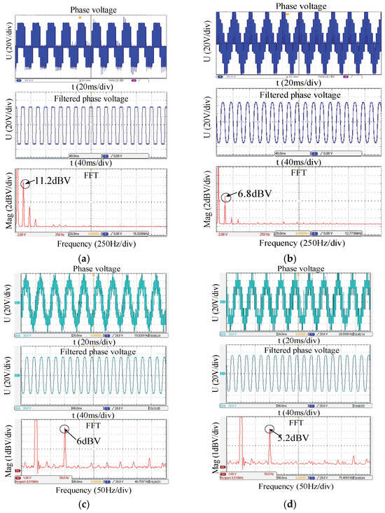
Figure 12.
Output phase voltage and its low-frequency spectrum analysis (m = 1.15). (a) M1. (b) M3.1. (c) M3.2. (d) M4.
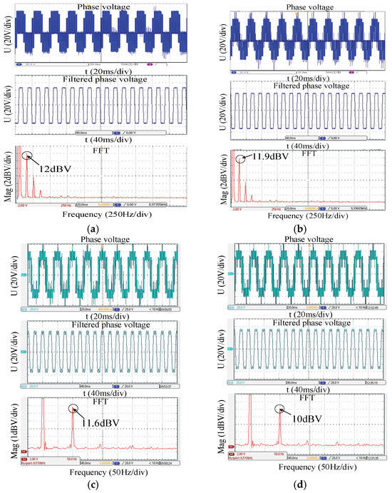
Figure 13.
Output phase voltage and its low-frequency spectrum analysis (m = 1.23). (a) M1. (b) M3.1. (c) M3.2. (d) M4.
Figure 12 and Figure 13 exhibit the output phase voltage waveforms, corresponding filtered waveforms and the Fast Fourier Transformation (FFT) for all the strategies at two different modulation ratios. It can be observed from the experimental results that the output phase voltage waveforms all contain a certain amount of low-order harmonic content, thus leading to the distortion of waveforms. Among all the harmonic content, the third harmonic content accounts for a large proportion, and it increases with the increase in the modulation ratio. Comparing four waveforms with the same modulation ratio, M1 results in the largest amount of the third harmonic, while M4 results in the lowest. When m is up to 1.23, the third harmonic content of all is more than 10 dBV, which demonstrates that the superiority of the FDF strategy almost disappears when the modulation ratio is large.
In summary, it can be observed that as the modulation ratio increases, the harmonic components in the output phase voltage of the inverter also increase. Comparative analysis of the experimental results of various overmodulation strategies reveals that, with the same modulation ratio, strategies with higher control flexibility exhibit better control over the third harmonic subspace. These strategies can effectively stabilize the output waveform with lower distortion levels in the phase voltage, thereby reducing unnecessary losses in multi-phase motors and further enhancing their operational performance.
6. Conclusions
High-performance modulation is the basis and premise of developing multi-phase motors and driving technology. Among all modulation strategies, SVPWM technology has obvious advantages. When it works in the overmodulation region, it can further increase the DBVU of inverters, thus broadening the operation range of machine apparently. This paper focuses on several SVPWM overmodulation strategies, which are compared in detail from the perspectives of DBVU and distortion of output voltage. Based on the above comparisons, distinctions and relationships of all the strategies are represented, and their characteristics and principles are summarized as well. Lastly, theoretical analysis was carried out via comparative simulations and experiments.
In all of these strategies, the NTV-SVPWM method is easy to understand and carry out. However, it unavoidably causes large accompanying vectors in the third harmonic subspace, which accelerates the development of NFV-SVPWM. Two algorithms of the SV-SVPWM method are both based on synthesizing a large vector and a medium vector in one direction as a new basic vector, and afterwards two new basic vectors are adopted to continue with the remaining steps. Compared with the NTV-SVPWM method, the SV-SVPWM method cuts down the third harmonic content to some extent, while the FDF-SVPWM overmodulation strategy results in the lowest harmonic content. In conclusion, for all the above overmodulation strategies, harmonic content of the output voltage would be increased if attempts to augment the modulation ratio are made. Also, overmodulation strategies with more CDFs can operate better when it comes to controlling the third harmonic subspace, which implies the output voltage with a lower distortion degree can be obtained.
Through meticulous comparison and analysis of various SVPWM overmodulation strategies, our research sheds light on their comparative performance characteristics and implications for system design and implementation. Specifically, we elucidate the distinctions, relationships and underlying principles of these strategies, offering engineers a deeper understanding of their practical implications.
It is particularly important to identify the most efficient strategies for reducing the third harmonic and minimizing the distortion of the waveform. Engineers can make use of these findings to optimize the performance of the system, increase efficiency and increase the reliability of the whole system. In essence, our research equips practicing engineers with valuable knowledge and insights that can inform their design decisions, refine implementation practices and ultimately lead to the development of more efficient and reliable multi-phase motor drive systems.
Moving forward, we plan to further extend our research by applying overmodulation strategies to the drive systems of electric vehicles with multiphase motors and to the power generation systems of multiphase motors in aerospace applications. This future work will explore the effects of overmodulation on different types of motors and generators, considering variations in power ratings and motor types. By conducting such research, we aim to gain a deeper understanding of the impact of overmodulation on system performance and efficiency across various application contexts.
Author Contributions
T.S. was responsible for the writing of the methodology, simulation verification and experiments in this work. Y.S. was responsible for the simulation verification. B.M. and Q.L. were responsible for the experiments. The supervision was mainly carried out by F.B. The review and editing of the paper were mainly carried out by Y.Q. and S.I.D. All authors have read and agreed to the published version of the manuscript.
Funding
This research was supported in part by the National Natural Science Foundation of China under Grant 52177050 and in part by the Fundamental Research Funds for the Central Universities of China under Grant NT2023007.
Data Availability Statement
The data used to support the findings of this study are available from the corresponding author upon request.
Conflicts of Interest
T.S. was employed by State Grid Jiangsu Electric Power Co., Ltd. Y.Q. was employed by China State Shipbuilding Corporation. The remaining authors declare that the research was conducted in the absence of any commercial or financial relationships that could be construed as a potential conflict of interest.
References
- Levi, E. Multiphase electric machines for variable-speed applications. IEEE Trans. Ind. Electron. 2008, 55, 1893–1909. [Google Scholar] [CrossRef]
- Levi, E.; Bojoi, R.; Profumo, F. Multiphase induction motor drive—A technology status review. IET Electr. Power Appl. 2007, 1, 489–516. [Google Scholar] [CrossRef]
- Meng, C.; Ouyang, H.; Liu, W. Space-vector PWM techniques for dual Y shift 30 degree permanent-magnet synchronous motor. Proc. CSEE 2010, 30, 90–98. [Google Scholar]
- Fuentes, E.J.; Silva, C.A.; Yuz, J.I. Predictive speed control of a two-mass system driven by a permanent magnet synchronous motor. IEEE Trans. Ind. Electron. 2011, 59, 2840–2848. [Google Scholar] [CrossRef]
- Parsa, L.; Toliyat, H.A. Fault-tolerant interior-permanent-magnet machines for hybrid electric vehicle applications. IEEE Trans. Veh. Technol. 2007, 56, 1546–1552. [Google Scholar] [CrossRef]
- Ding, X.; Du, M.; Duan, C.; Guo, H.; Xiong, R.; Xu, J.; Chen, J.; Luk, P. Analytical and Experimental Evaluation of SiC-Inverter Nonlinearities for Traction Drives Used in Electric Vehicles. IEEE Trans. Veh. Technol. 2018, 67, 146–159. [Google Scholar] [CrossRef]
- Apsley, J.M.; Gonzalez-Villasenor, A.; Barnes, M.; Smith, A.C.; Williamson, S.; Schuddebeurs, J.D.; Norman, P.J.; Booth, C.D.; Burt, G.M.; McDonald, J.R. Propulsion drive models for full electric marine propulsion systems. IEEE Trans. Ind. Appl. 2009, 45, 676–684. [Google Scholar] [CrossRef]
- Gao, F.; Tan, Y.; Tao, Y.P.; Xu, Z.F.; Li, X.F.; Zheng, X.X. Research on the Integrated Control Strategy of Electric Vehicle Driving and Charging. Electr. Power Eng. Technol. 2018, 37, 73–77+113. [Google Scholar]
- Zhou, K.L.; Wang, D.W. Relationship between space-vector modulation and three-phase carrier-based PWM: A comprehensive analysis. IEEE Trans. Ind. Electron. 2002, 49, 186–196. [Google Scholar] [CrossRef]
- Yang, G.J.; Sun, L.; Cui, N.Z. Study on method of the space vector PWM. Proc. CSEE 2001, 21, 79–83. [Google Scholar]
- HLu, F.; Qu, W.L.; Zhang, L. SVPWM algorithm based on modulation functions. Trans. China Electrotech. Soc. 2008, 23, 37–43. [Google Scholar]
- Xue, X.; Zhao, W.; Zhu, J.; Liu, G.; Zhu, X.; Cheng, M. Design of five-phase modular flux-switching permanent-magnet machines for high reliability applications. IEEE Trans. Magn. 2013, 49, 3941–3944. [Google Scholar] [CrossRef]
- Bodo, N.; Jones, M.; Levi, E. A space vector PWM with common-mode voltage elimination for open-end winding five-phase drives with a single DC supply. IEEE Trans. Ind. Electron. 2013, 61, 2197–2207. [Google Scholar] [CrossRef]
- Shi, R.; Toliyat, H.A. Vector Control of Five-Phase Synchronous Reluctance Motor with Space Vector Pulse Width Modulation (SVPWM) for Minimum Switching Losses; APEC: Dallas, TX, USA, 2002; pp. 57–63. [Google Scholar]
- Chen, K.-Y.; Xie, Y.-L. Reducing harmonics distortion in five-phase VSI using space-vector-based optimal hybrid PWM. IEEE Trans. Power Electron. 2017, 32, 2098–2113. [Google Scholar] [CrossRef]
- Gao, H.W.; Yang, G.J.; Liu, J. Research of space vector PWM techniques for five-phase voltage source inverter. Proc. CSEE 2014, 34, 2917–2925. [Google Scholar]
- Dujic, D.; Grandi, G.; Jones, M.; Levi, E. A space vector PWM scheme for multifrequency output voltage generation with multiphase voltage-source inverters. IEEE Trans. Ind. Electron. 2008, 55, 1943–1955. [Google Scholar] [CrossRef]
- Bolognani, S.; Calligaro, S.; Petrella, R. Adaptive flux-weakening controller for interior permanent magnet synchronous motor drives. IEEE J. Emerg. Sel. Top. Power Electron. 2014, 2, 236–248. [Google Scholar] [CrossRef]
- Liu, Y.S.; Qiao, M.Z.; Zhu, P. Research on over-angle weakening control strategy based on SVPWM overmodulation. Electr. Mach. Control Appl. 2018, 45, 28–33. [Google Scholar]
- Abassi, M.; Khlaief, A.; Saadaoui, O.; Chaari, A. Performance Analysis of FOC and DTC for PMSM Drives Using SVPWM Technique; STA: Monastir, Tunisia, 2015; pp. 228–233. [Google Scholar]
- Jiang, Z.; Bu, F.F.; Pan, Z.H.; Xuan, F.Q. Improved deadbeat current control algorithm for permanent magnet synchronous motor servo system. Electr. Power Eng. Technol. 2020, 39, 177–183. [Google Scholar]
- Xiang, Z.; Zhou, Y.; Zhu, X.; Quan, L.; Fan, D.; Liu, Q. Research on characteristic airgap harmonics of a double rotor flux-modulated PM motor based on harmonic dimensionality reduction. IEEE Trans. Transp. Electrif. 2023. [Google Scholar] [CrossRef]
- Toliyat, H.A.; Shi, R.; Xu, H.S. A DSP-based vector control of five-phase synchronous reluctance motor. IEEE Trans. Ind. Appl. 2000, 4, 432–437. [Google Scholar]
- Xu, P.; Zhu, Z.Q. Novel Carrier Signal Injection Method Using Zero Sequence Voltage for Sensorless Control of PMSM Drives. IEEE Trans. Ind. Electron. 2016, 63, 2053–2061. [Google Scholar] [CrossRef]
- Karugaba, S.; Ojo, O. A carrier-based PWM modulation technique for balanced and unbalanced reference voltages in multiphase voltage-source inverters. IEEE Trans. Ind. Appl. 2012, 48, 2102–2109. [Google Scholar] [CrossRef]
- Duran, M.J.; Prieto, J.; Barrero, F.; Riveros, J.A.; Guzman, H. Space-vector PWM with reduced common-mode voltage for five-phase induction motor drives. IEEE Trans. Ind. Electron. 2012, 60, 4159–4168. [Google Scholar] [CrossRef]
- Prieto, J.; Jones, M.; Barrero, F.; Levi, E.; Toral, S. Comparative analysis of discontinuous and continuous PWM techniques in VSI-fed five-phase induction motor. IEEE Trans. Ind. Electron. 2011, 58, 5324–5335. [Google Scholar] [CrossRef]
- Marouani, K.; Baghli, L.; Hadiouche, D.; Kheloui, A.; Rezzoug, A. A new PWM strategy based on a 24-sector vector space decomposition for a six-phase VSI-fed dual stator induction motor. IEEE Trans. Ind. Electron. 2008, 55, 1910–1920. [Google Scholar] [CrossRef]
- Bu, F.; Pu, T.; Liu, Q.; Ma, B.; Degano, M.; Gerada, C. Four-Degree-of-Freedom Overmodulation Strategy for Five-Phase Space Vector Pulse Width Modulation. IEEE J. Emerg. Sel. Top. Power Electron. 2020, 9, 1578–1590. [Google Scholar] [CrossRef]
- Barrero, F.; Duran, M.J. Recent advances in the design, modeling, and control of multiphase machines. IEEE Trans. Ind. Electron. 2016, 63, 449–458. [Google Scholar] [CrossRef]
- Mohammadpour, A.; Sadeghi, S.; Parsa, L. A generalized fault-tolerant control strategy for five-phase PM motor drives considering star, pentagon and pentacle connections of stator windings. IEEE Trans. Ind. Electron. 2013, 61, 63–75. [Google Scholar] [CrossRef]
- Levi, E.; Satiawan, I.N.W.; Bodo, N.; Jones, M. A space-vector modulation scheme for multilevel open-end winding five-phase drives. IEEE Trans. Energy Convers. 2011, 27, 1–10. [Google Scholar] [CrossRef]
- Duran, M.J.; Riveros, J.A.; Barrero, F.; Guzman, H. Reduction of common-mode voltage in five-phase induction motor drives using predictive control techniques. IEEE Trans. Ind. Appl. 2016, 48, 2059–2067. [Google Scholar] [CrossRef]
- Rangari, S.C.; Suryawanshi, H.M.; Shah, B. Implementation of Large and Medium Vectors for SVPWM Technique in Five Phase Voltage Source Inverter; ICICCS: Madurai, India, 2017; pp. 751–775. [Google Scholar]
Disclaimer/Publisher’s Note: The statements, opinions and data contained in all publications are solely those of the individual author(s) and contributor(s) and not of MDPI and/or the editor(s). MDPI and/or the editor(s) disclaim responsibility for any injury to people or property resulting from any ideas, methods, instructions or products referred to in the content. |
© 2024 by the authors. Licensee MDPI, Basel, Switzerland. This article is an open access article distributed under the terms and conditions of the Creative Commons Attribution (CC BY) license (https://creativecommons.org/licenses/by/4.0/).
