Article

Common-Mode Voltage Reduction Method Based on Variable Sampling Frequency Finite Control Set-Model Predictive Control for PMSM Drive Systems

1
Department of Electrical and Computer Engineering, College of Information and Communication Engineering, Sungkyunkwan University, Suwon 16419, Republic of Korea
2
Electric Propulsion Research Center, Korea Electrotechnology Research Institute (KERI), Changwon 51541, Republic of Korea
3
Dawonsys Co., Ltd., Anyang 15655, Republic of Korea
*
Author to whom correspondence should be addressed.
Energies 2024, 17(6), 1443; https://doi.org/10.3390/en17061443
Submission received: 13 February 2024 / Revised: 6 March 2024 / Accepted: 15 March 2024 / Published: 17 March 2024
(This article belongs to the Special Issue Advanced Control in Power Electronics, Drives and Generators)

Abstract

:
In this article, a finite control set-model predictive control (FCS-MPC) with variable sampling time is proposed. A zero-voltage vector appears in the dead time between specific voltage vectors, resulting in an unintentionally large common-mode voltage. Herein, a large common-mode voltage was suppressed, and the load current was controlled using a voltage vector combination that did not cause a zero-voltage vector in dead time. Additionally, to improve the total harmonic distortion (THD) of the load current, the intersection of the predicted current and the command current by all the volage vectors (VVs) in the combination is confirmed. The VV where the intersection occurs is selected as the optimal VV. This optimal VV is applied to the point where the predicted current and the reference current intersect. The applicable range of the sampling time should be selected by considering the calculation time and number of switching. Through the proposed FCS-MPC strategy, not only can the common-mode voltage be limited to within ±Vdc/6, but an improved THD can also be obtained compared to the existing method using fixed sampling. The proposed method was verified through PSIM simulation and experimental results.

1. Introduction

Voltage source inverters (VSIs) have recently been widely utilized in various energy conversion systems. VSIs, comprising advanced power switching devices, offer improved power quality based on rapid switching operations [1,2,3,4,5]. However, as the switching operations of VSIs accelerate, the issue of common-mode voltage (CMV) tends to increase. Therefore, various approaches have been proposed to reduce the CMV in VSI systems.
One method for suppressing CMV is the use of an active CMV filter [6]. However, hardware solutions, including active CMV filters, require additional auxiliary components, such as common-mode transformers or additional switches [7,8]. Consequently, the system volume increases, and the optimal design of the filter becomes complex. Because of these demands, it has not been considered an attractive option.
Alternatively, finite-control set-model predictive control (FCS-MPC) has been studied as a way to reduce CMV without additional hardware. All switching states of the two-level voltage source inverter (2L-VSI) and CMV voltages are shown in Table 1. Zero-voltage vectors (ZVVs) induce peak CMV; thus, CMV can be mitigated by excluding the ZVV and synthesizing the reference voltages. To replace ZVVs, voltage vectors (VVs) with the same magnitude and opposite direction can be used [9]. However, an indiscriminate VV synthesis without consideration of the dead time interval can lead to unintended peak CMV occurrences.
In [10], reference voltages were synthesized, excluding vector transitions that induce peak CMV during the dead time interval. In this case, as the number of available non-ZVVs decreases, the total harmonic distortion (THD) of the load current increases.
In [11,12,13,14,15,16,17,18], the CMV was reduced using a fixed switching frequency. With a fixed switching frequency, lower THD can be achieved with higher switching frequencies, but, unfortunately, switching losses increase simultaneously. In the case of FCS-MPC, where switching vectors are determined at each sampling period, increasing the sampling frequency also leads to an increase in switching losses.
This article proposes a CMV reduction strategy based on variable sampling frequency FCS-MPC. Considering the dead time interval and excluding cases where the peak CMV occurs during vector transitions, a limited number of VV combinations are used to reduce the CMV. The cost function is constructed based on the predicted errors in the d-axis and q-axis, and the intersection of the reference current and the predicted current is predicted to determine the next sampling point. Because the predicted current error has a minimum value at the intersection point, the proposed variable sampling method can achieve a low THD for the load current. Consequently, the proposed method can minimize CMV between +Vdc/6 and −Vdc/6 and achieve lower switching losses and THD compared to fixed sampling frequency methods.
The remainder of this article is organized as follows. Section 2 reviews current control using FCS-MPC for conventional CMV reduction methods. Section 3 presents VV combinations that do not induce peak CMV, while considering the dead time interval. The proposed CMV reduction strategy based on the variable sampling frequency FCS-MPC is described in Section 4. The simulation results and experimental findings validating the proposed FCS-MPC strategy are presented in Section 5 and Section 6, respectively. Finally, Section 7 concludes this article.

2. Review of Conventional FCS-MPC for CMV Reduction

As shown in Figure 1, the CMV is represented based on the pole voltages van, vbn, and vcn of the VSI:
v C M = ( v a n + v b n + v c n ) / 3 .
The stator voltage equation of a permanent magnet synchronous machine (PMSM) drive system, which includes stator impedance, is expressed as follows:
v s = R s i + L s d i d t + E s ,
where Rs, Ls, and Es represent the stator resistance, stator inductance, and back electromotive force (EMF), respectively. In this case, because the FCS-MPC is based on a discretized model, the differentiation of the load current is approximated using Euler’s approximation as follows:
d i d t = i k + 1 i ( k ) T s .
where i(k) represents the k-th sampled current, and Ts indicates the sampling period.
By substituting (3) into (2), the predicted future current can be obtained as follows:
i k + 1 = 1 R s · T s L s × i k + T s L s v s k E s k .
By applying seven VVs to the k-th sampled v(k), seven future currents can be predicted. The predicted future currents can be substituted for the d-axis and q-axis predicted currents, and the current error is the difference between the i(k + 1) and the reference currents along each axis. Therefore, cost function g can be expressed as follows:
g = i d ( k + 1 ) i d ( k + 1 ) + i q ( k + 1 ) i q ( k + 1 ) .
Selecting the vector that minimizes cost function g and applying it during the sampling period minimizes the error between the predicted future currents and actual sampled currents at each sampling instance. Figure 2 illustrates reference values i r e f d , i r e f q , predicted d-axis and q-axis current waveforms resulting from various VVs.
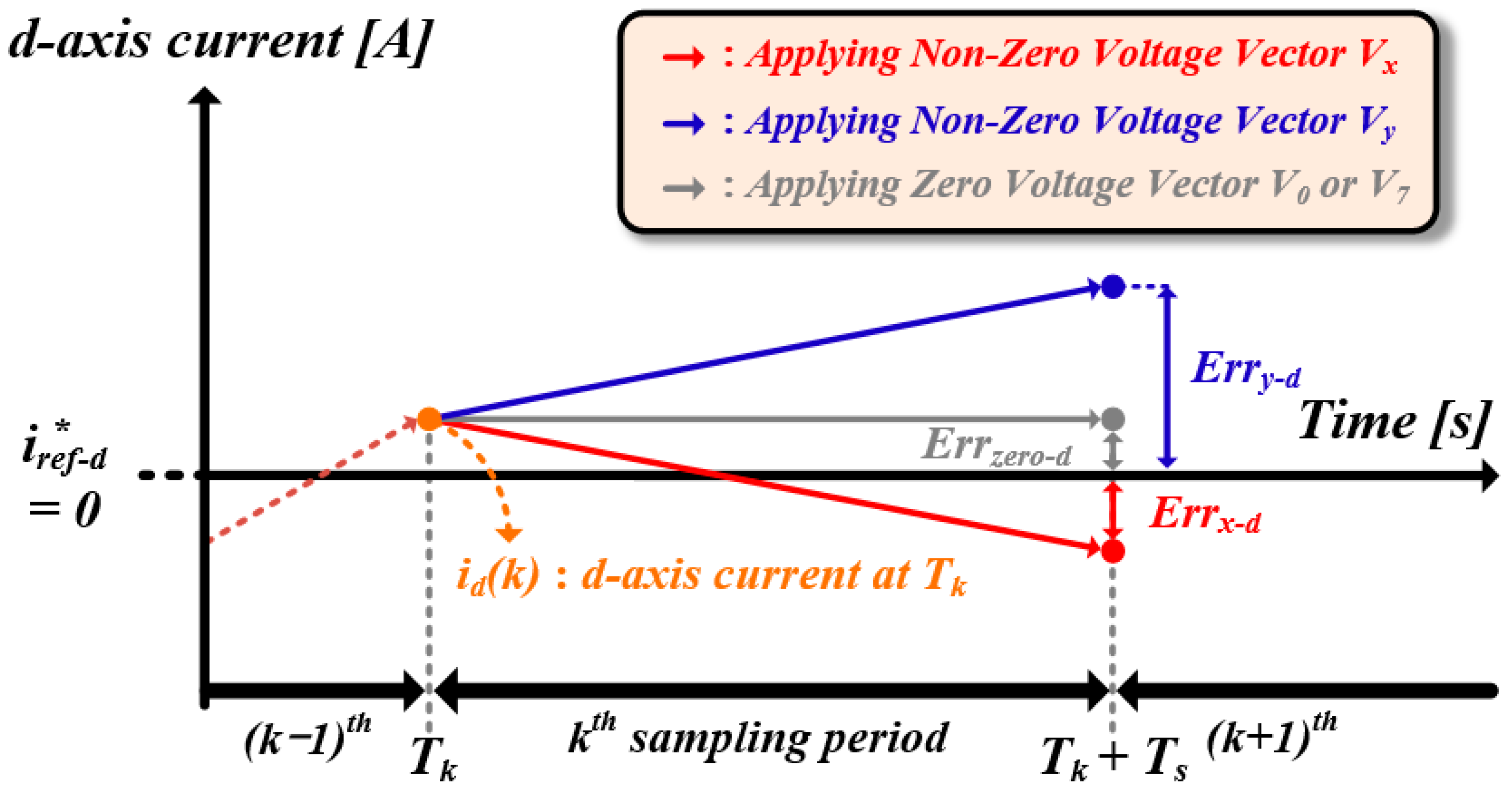
However, using the ZVV to synthesize the reference voltages leads to a peak CMV. Therefore, to limit the magnitude of CMV to V d c / 6 , only a non-ZVV was applied to synthesize the reference voltages. Figure 3 shows the future predicted currents along the d-axis with the ZVV and two non-ZVVs applied, respectively. When the ZVV was applied, the future prediction error, represented by E r r z e r o d , was smaller than the errors E r r x d and E r r y q when the other two non-ZVVs were applied. This suggests that the ZVV is the optimal VV. However, to mitigate CMV, an alternative, Vx, is applied. The intentional application of a non-ZVV results in significant current ripple and current error compared with the optimal VV. Therefore, the THD of the load current increased.
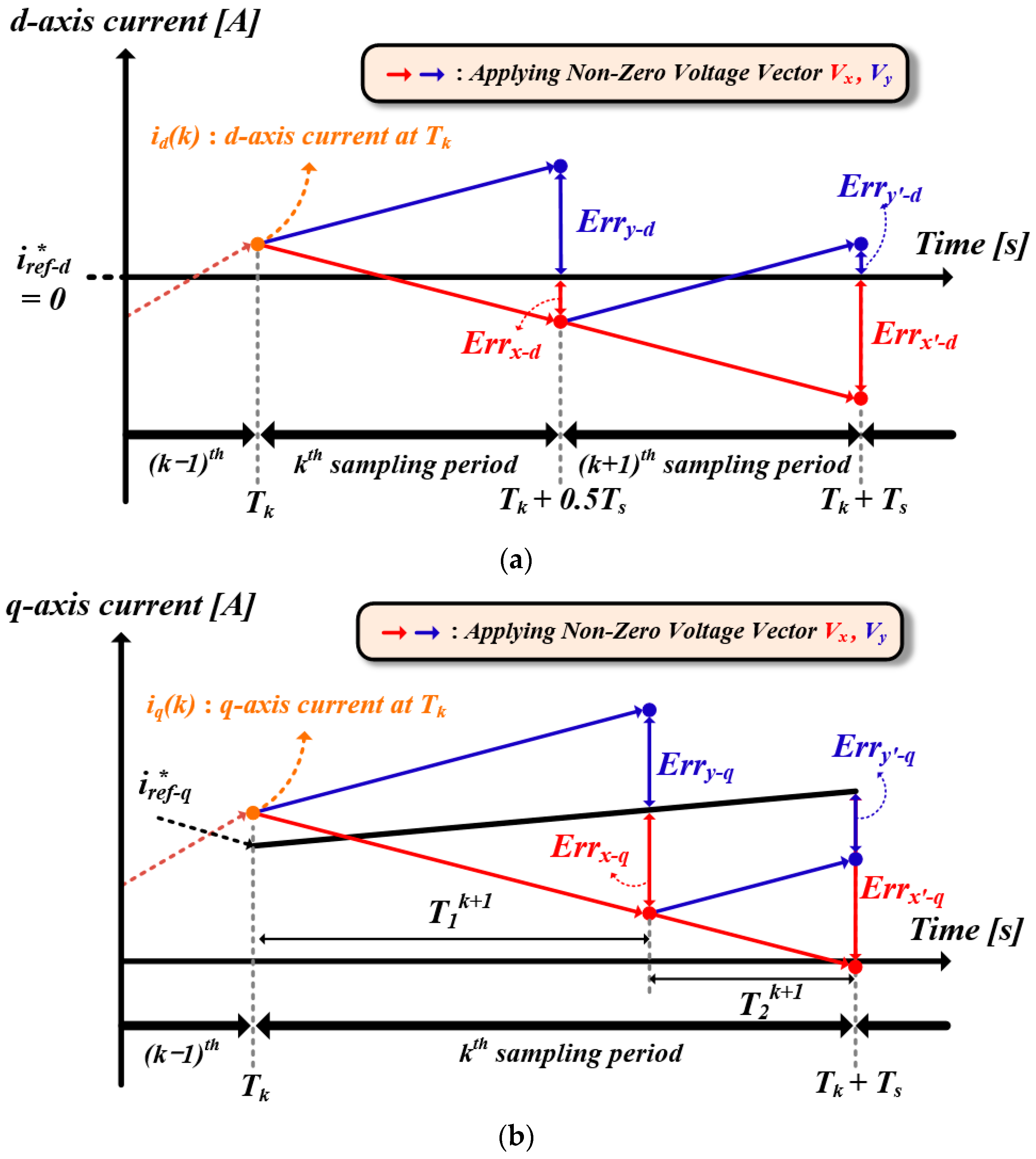
To reduce current ripple, two methods have been proposed: applying a high sampling frequency and synthesizing two non-ZVVs within a single sampling interval. Figure 4 depicts the predicted current waveforms for both methods. When setting a short sampling period, the inverter outputs the optimal VV with the minimum cost function at each sampling instance, resulting in a low current ripple and current error, but incurring significant switching losses. In addition, synthesizing two non-ZVVs within one sampling interval also increases the switching losses owing to VV changes.

3. Consideration of the Dead Time Interval

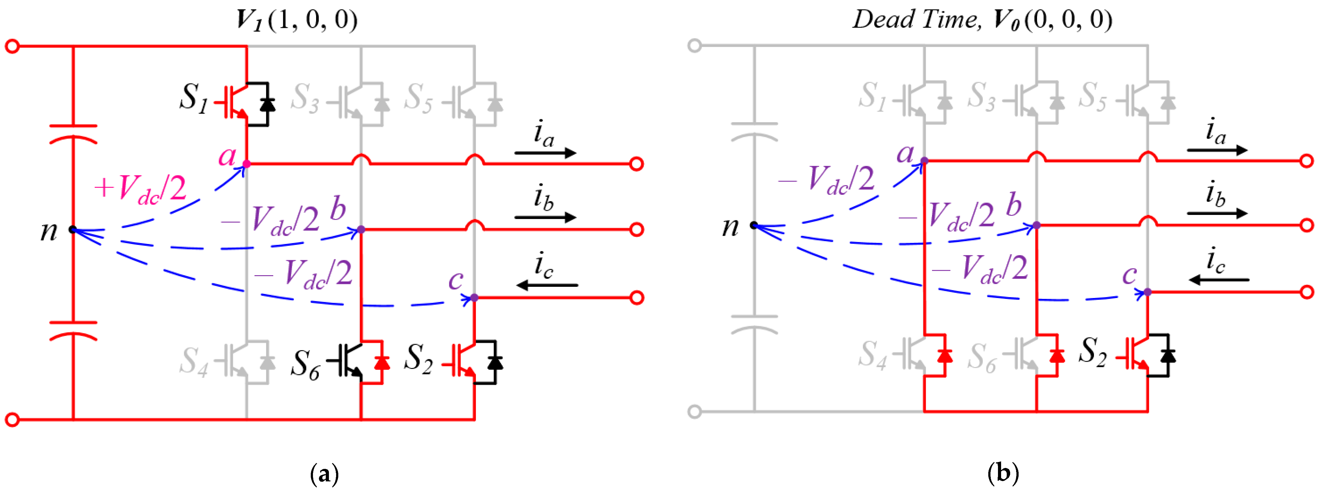
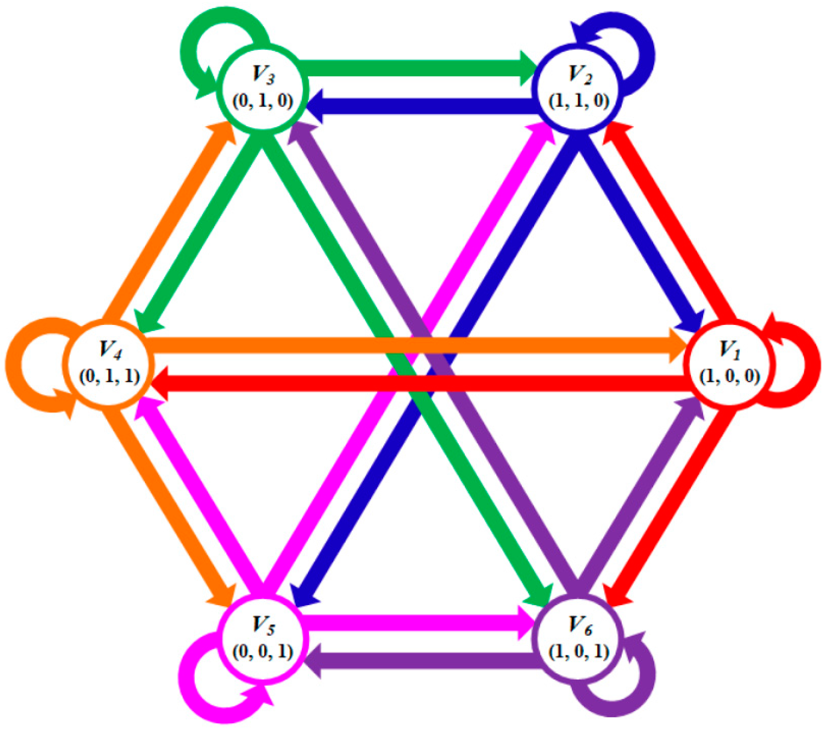
Despite excluding the ZVV from the reference VV synthesis process to mitigate the CMV, an unintended peak CMV occurred when the circuit was configured with the same switching states as the ZVV during the dead time interval. Therefore, the peak CMV could not be completely eliminated without considering the dead time between switching state transitions. Therefore, it is necessary to consider the vector transitions that result in the peak CMV. For instance, Figure 5 illustrates the VV transition where the switch state becomes V0 (0,0,0) during the dead time. During the switch state V1 (1,0,0), S1 is on, whereas S6 and S2 are on. During the dead time interval from V1 (1,0,0) to V3 (0,1,0), S1 and S6 turn off. In this case, both the top and bottom switches of phase a are off, and the current ia flows through the reverse-parallel diode at S4. Therefore, during this dead time interval, the CMV has a peak value of V d c / 2 . Table 2 lists the VV transitions that result in the peak CMV during the dead time. As shown in Table 2, the peak CMV occurs during transitions between odd or even vectors. Hence, to eliminate the peak CMV, the algorithm should be designed to alternate between odd and even VVs for the output. Figure 6 shows all the VV transitions with a CMV of V d c / 6 .

4. Proposed FCS-MPC with Variable Sampling for CMV Reduction

In this section, we propose the FCS-MPC for CMV reduction based on variable sampling, aiming not only to improve the current THD, but also to reduce the number of switching events compared to fixed sampling methods. This section establishes how the cost function has its minimum at the intersection of the reference current and future predicted current, and the sampling time when the cost function is minimized by considering both d-axis and q-axis.

4.1. Minimum Value of Cost Function in Proposed Method

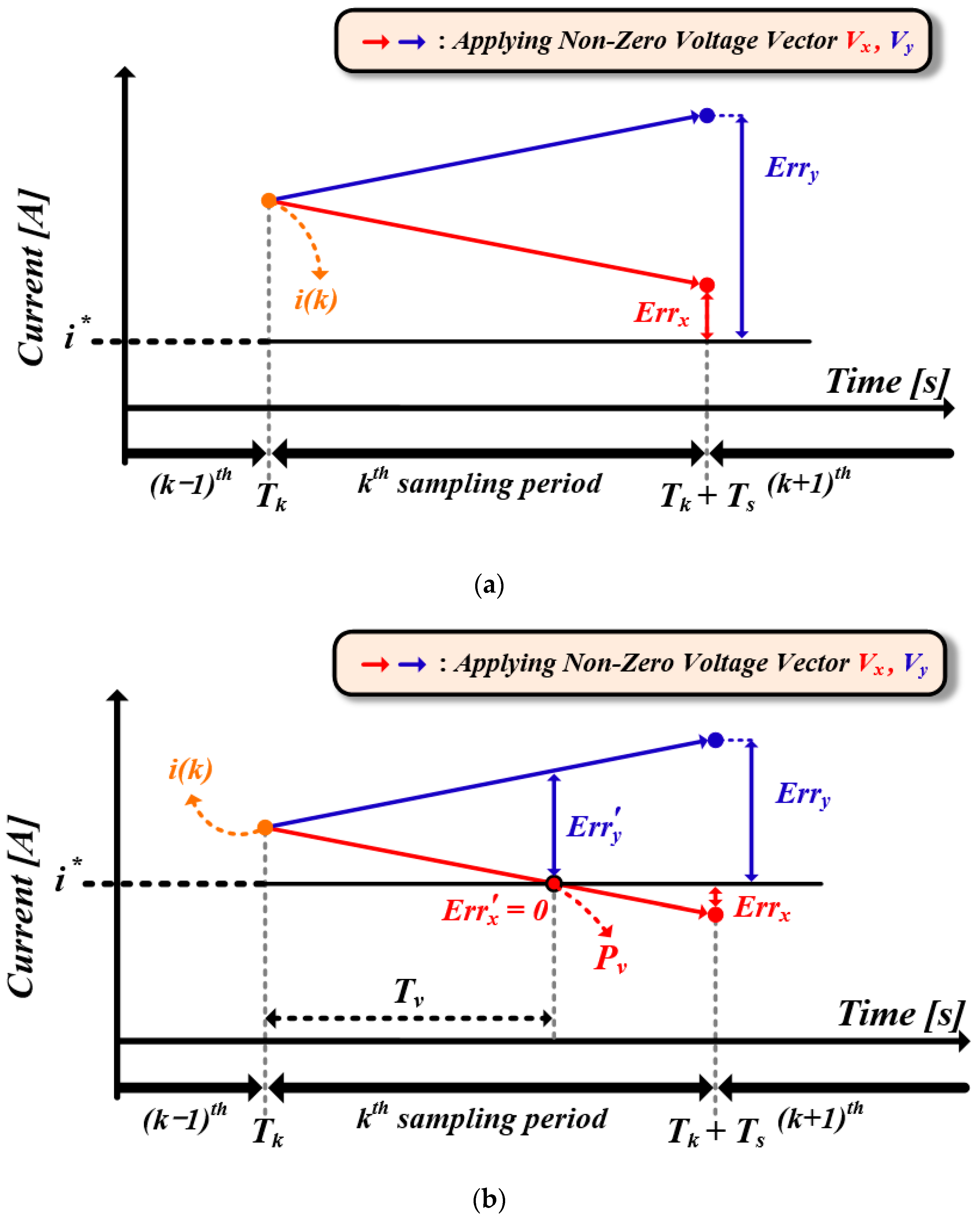
Figure 7 shows both cases where intersections between the predicted future current and the reference current are present and absent. In cases where there is no intersection within the sampling interval, maintaining the existing sampling period yields the smallest cost function value. Conversely, when there is an intersection, the smallest cost function value is attained at the intersection point Pv. Therefore, Pv yields the smallest current ripple and current error.

4.2. Calculation of Variable Sampling Period

The intersection between the predicted future current and the command current was obtained using the error equation. Expressing the current as a function of time using (2) yields the following:
i t = i k × e R s L s T s + v s k E s k R s 1 e R s L s T s ,
where i(k) represents the initial value of the current, i.e., the currently measured value. Defining the current error equation over time as (7), the current error equation can be expressed as (8):
E r r t = i t i t ,
E r r t = i t i k × e R s L s T s + v s k E s k R s 1 e R s L s T s ,
where i t denotes the reference current. Therefore, the intersection point Tv between the predicted future current and commanded current is expressed as follows:
T v = L s R s × i k i [ i k v s k E s k R s ]
However, because current control occurs on both the d-axis and q-axis, consideration of both axes is necessary. Figure 8 illustrates a scenario with an intersection on only one axis. When the current error on the q-axis was zero, the error on the d-axis was significant. Thus, because the errors on each axis are independent, effectively reducing the current ripple requires sampling when the sum of the errors on both axes is minimized. The current error equations for each axis are as follows:
E r r d t = i d t i d k × e R s L d T s + v s , d k E s , d k R s 1 e R s L d T s ,
E r r q t = i q t i q k × e R s L q T s + v s , q k E s , q k R s 1 e R s L q T s .
The time Tv at which the sum of the current errors is minimized can be found through differentiation and is expressed as follows:
T v = i d t i d k × J d + i q t i q k × J q [ J q ( k ) 2 ( J d ( k ) ) 2 ] ,
where J d ( k ) and J q ( k ) are
J d k = R s × i d k v s , d k + E s , d k L d ,
J q k = R s × i q k v s , q k + E s , q k L q .

4.3. Applicable Range of Variable Sampling

To implement a variable sampling period, the computations involved in predicting future currents must be considered. Without considering the time required for computation, outputting VVs at the points of the minimum cost function may degrade the current characteristics. Figure 8 illustrates the interval in which variable sampling can be applied. For instance, if the point with the minimum cost function is within an inapplicable region, sampling should occur at tk + Tmin, the point within the applicable range that minimizes the cost function, to prevent degradation of the current characteristics. Therefore, in this case, the sampling period was set to Tmin. Conversely, if the point with the minimum cost function is within the applicable region, sampling is performed at tk + Tv, which is the computed sampling point. Therefore, the sampling period was Tv.
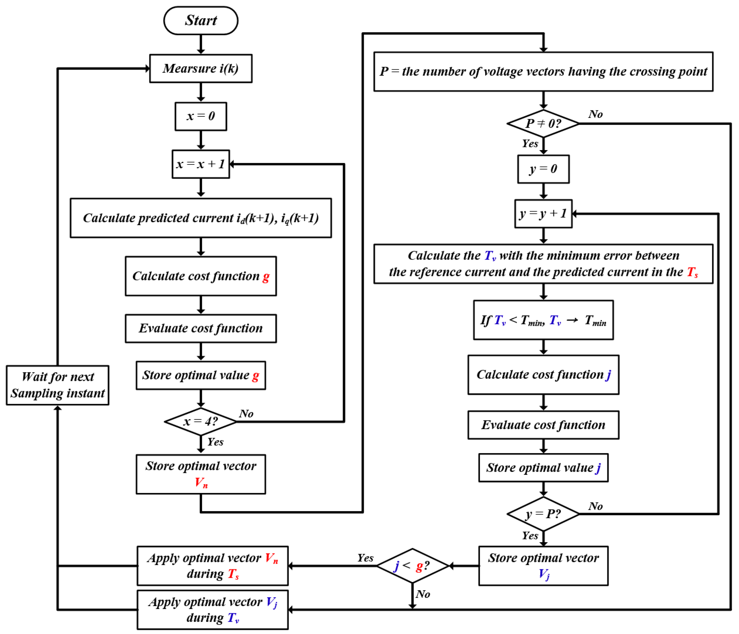
The FCS-MPC algorithm incorporating the proposed variable sampling period is depicted in Figure 9. First, the MPC computation was performed considering only four specific non-ZVVs. Then, the intersection between the command current and the predicted future current was confirmed. If there were no intersections, the sampling period was set to Ts. If there was an intersection, Tmin and Tv were compared to determine the sampling period. In this article, the default Ts was set to 100 [μs], and Tmin was set to 50 [μs].

5. Simulation Results

The proposed FCS-MPC method was simulated using a surface-mounted permanent magnet synchronous motor (SPMSM) drive system with the Power SIM program at 750 [rpm], with q-axis current references set to 0 [A], 6 [A], and 7.5 [A]. The simulation parameters are presented in Table 3. The fixed sampling was simulated at 10 and 20 kHz, and the sampling frequency for the proposed method was between 10 and 20 kHz. The simulation results are presented in the following order: FCS-MPC for current control, FCS-MPC excluding ZVV, FCS-MPC excluding ZVV considering dead time (sampling frequencies: 10 and 20 kHz), and the proposed FCS-MPC with a variable sampling frequency between 10 and 20 kHz.

5.1. FCS-MPC for Current Control

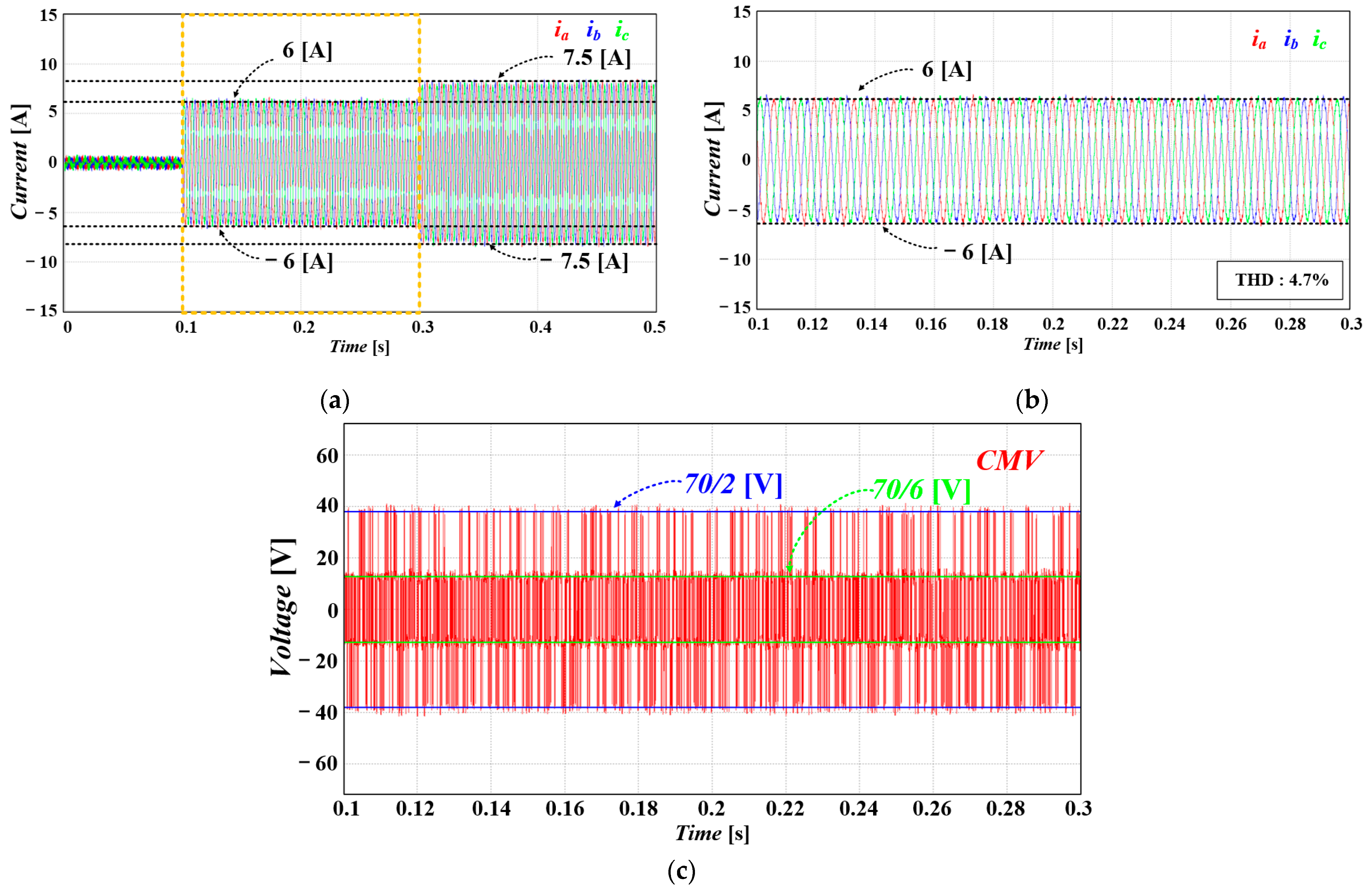
Figure 10 shows the simulation results of MPC with both ZVVs and non-ZVVs applied. The sampling frequency was fixed at 10 kHz. Figure 10b represents the magnified waveforms of the highlighted part in Figure 10a. Because the FCS-MPC for current control utilizes all applicable VVs, it always outputs the optimal VVs with the minimum cost function, resulting in a current THD of 4.7%. Figure 10c illustrates the CMV from 0.1 t to 0.3 t when the q-axis current reference is 6 [A]. As ZVV usage and transitions between VVs were not considered, the CMV ranges up to the maximum value of ±70/2 [V]. In the case of MPC, where VVs are used without restriction to synthesize the reference VV, a low THD can be obtained; however, it should be noted that a peak CMV occurs.

5.2. FCS-MPC Excluding ZVV

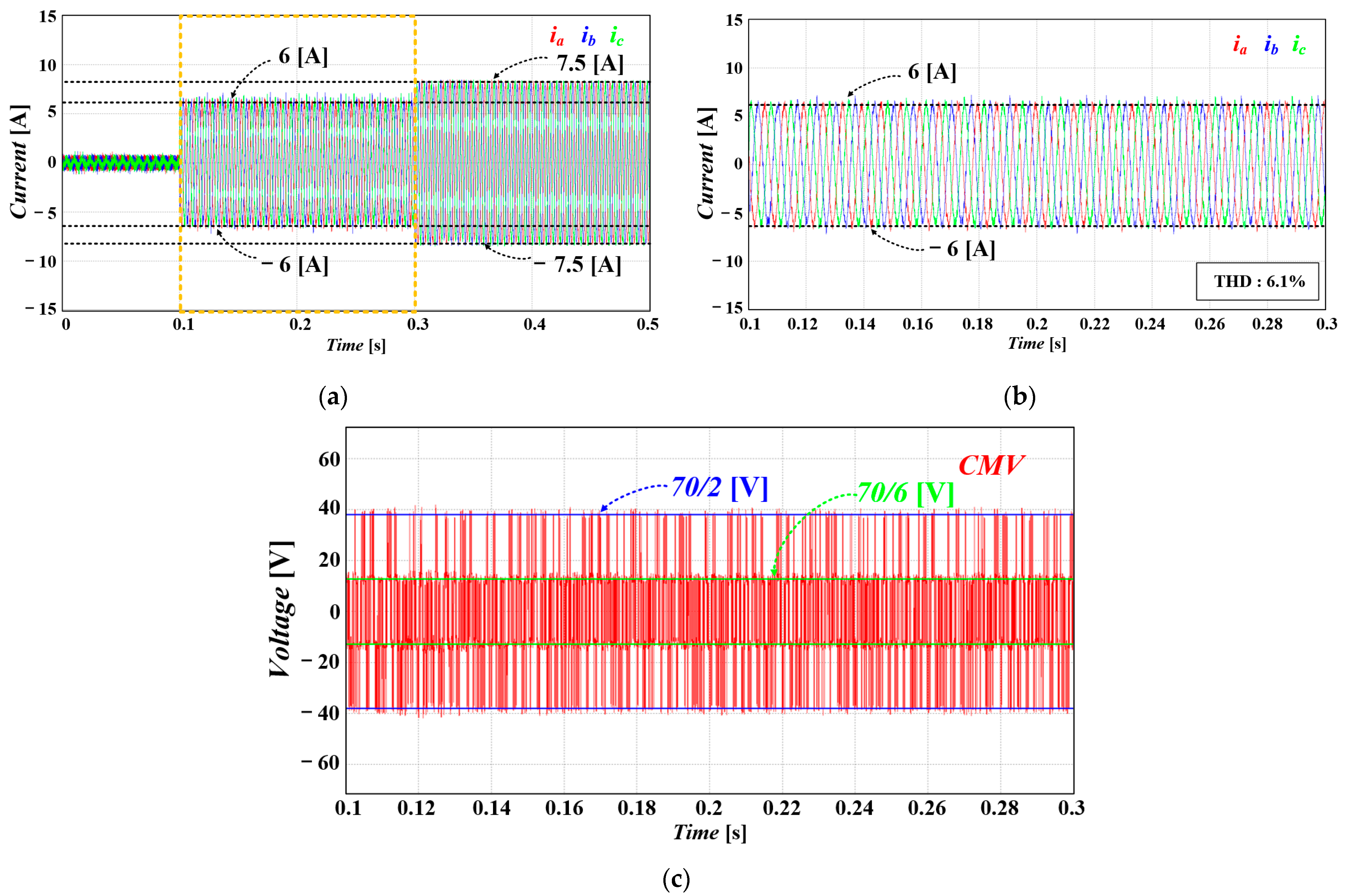
Figure 11 shows the simulation results of FCS-MPC using only non-ZVVs. The sampling frequency was fixed at 10 kHz for comparison with that described in Section 5.1. Figure 11b shows that the current THD is 6.1%, which is higher than that shown in Figure 10b. Because of the process of synthesizing the reference VV excluding ZVVs, VVs other than ZVVs were selected as the optimal VV and applied, leading to increased current error. This means that VVs with larger cost functions than those in Section 5.1 are selected as the optimal VV.
Figure 11c shows the CMV when synthesizing the command voltage excluding non-ZVVs. Excluding ZVVs reduced the occurrence of CMV with the maximum value of ±70/2 [V]. However, because vector combinations with the same circuit as ZVVs were not excluded during the dead time interval, the resulting peak CMV remained unresolved.

5.3. FCS-MPC Excluding ZVV with the Consideration of Dead Time (Sampling Frequencies: 10 kHz, 20 kHz)

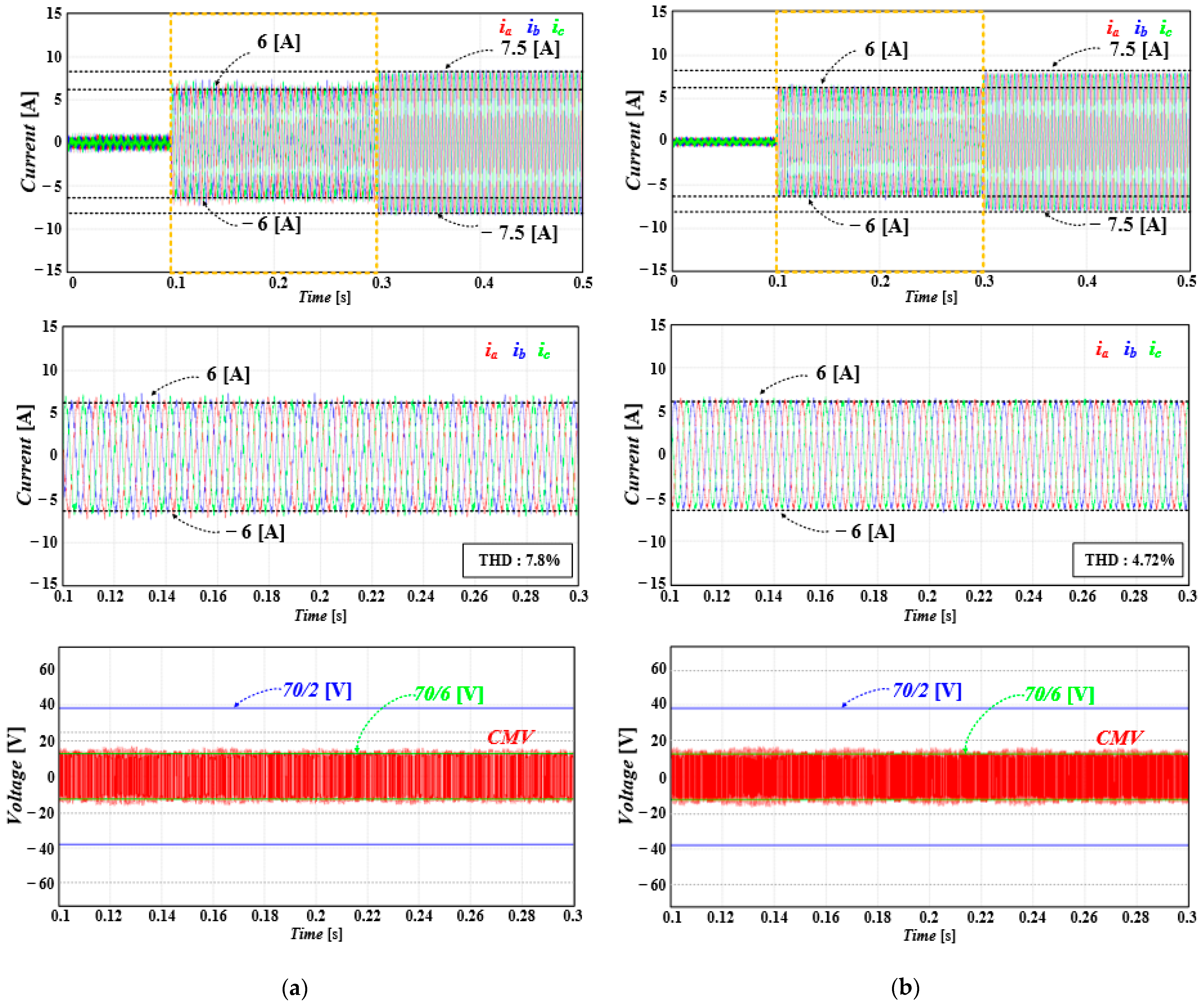
Figure 12 shows the simulation results of FCS-MPC using only non-ZVVs and considering the dead time interval. In addition, simulations were conducted by changing the sampling frequency to 10 and 20 kHz to compare the results with varying sampling frequencies. Figure 12a represents the simulation results for a sampling frequency of 10 kHz. Only four VVs are available for synthesizing the reference voltage. Therefore, VVs with larger cost functions than those in Section 5.2 must be selected. For example, when v(k) is V1, v(k + 1) should be selected from V1, V2, V4, and V6. This is because the selection of other VVs may induce the peak CMV. Therefore, although peak CMV removal was possible, it resulted in a high THD of 7.8%. Figure 12b shows the simulation results when the sampling frequency was increased to 20 kHz to reduce THD. Owing to the higher sampling frequency, the THD of the load current decreased by 3.08% to 4.72% compared to when the sampling frequency was 10 kHz. However, in the case of the FCS-MPC, an increase in sampling frequency implies an increase in switching frequency. Therefore, changing the sampling frequency to 20 kHz increased the switching losses compared with having the sampling frequency at 10 kHz.

5.4. Proposed FCS-MPC for CMV Reduction with Variable Sampling Frequency

Figure 13 shows the simulation results of the FCS-MPC for CMV reduction with the proposed variable sampling frequency. As shown in Figure 13b, the THD of the load current is improved by 2.92% to 4.88% compared with the conventional method with a fixed sampling frequency of 10 kHz. Furthermore, Figure 13c shows that the proposed method utilizes only non-ZVVs and considers the dead time interval to output future VVs. Therefore, it can perfectly eliminate the peak CMV. Figure 13d shows the ramp function, which resets at each sampling point, and the value before the reset indicates the variable sampling period. The proposed method determines the sampling period between the minimum value of 50 [μs] and the maximum value of 100 [μs], and the determined sampling period is when the cost function has a minimum value for both the d-axis and q-axis errors. Therefore, the current error is minimized at the determined sampling points, resulting in a low THD. Consequently, compared to the conventional method with a fixed sampling frequency of 20 kHz, although the THD increased by 0.16%, it had fewer switching.

6. Experimental Results

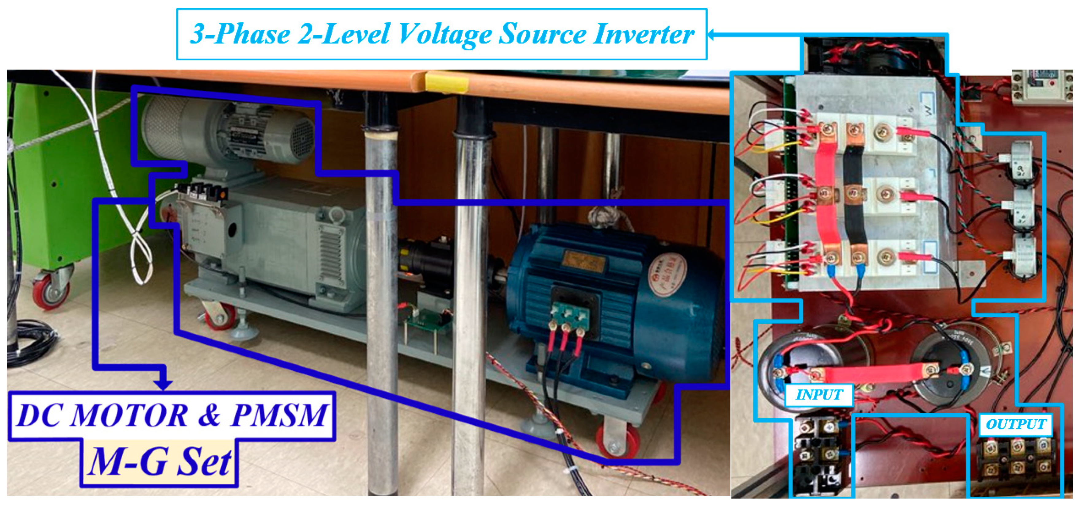
To validate the performance of the proposed FCS-MPC method, experiments were conducted using a motor–generator (M–G) set. Figure 14 illustrates the M–G set and 2L-VSI used in the experiment. The experimental parameters were identical to the simulation parameters, and the proposed algorithm was implemented using a TMS320F28377S from Texas Instruments (Dallas, TX, USA). Using the proposed method, the load motor (DC motor) was controlled in the speed control mode, whereas the target motor, a PMSM, was controlled in the torque control mode.

6.1. FCS-MPC for Current Control

Figure 15 shows the experimental results for the FCS-MPC with current control at 750 [rpm]. Figure 15b shows a magnified waveform of Figure 15a. As shown in Figure 15, the FCS-MPC for current control determines the optimal VVs without constraints on the VV selection. Therefore, the THD of the load current was 5.4%. Figure 15c illustrates the CMV of FCS-MPC for current control. Due to unrestricted VV selection, peak CMV occurring at the ZVV or dead time intervals is not mitigated, resulting in ±Vdc/2 being observed.

6.2. FCS-MPC Excluding ZVV

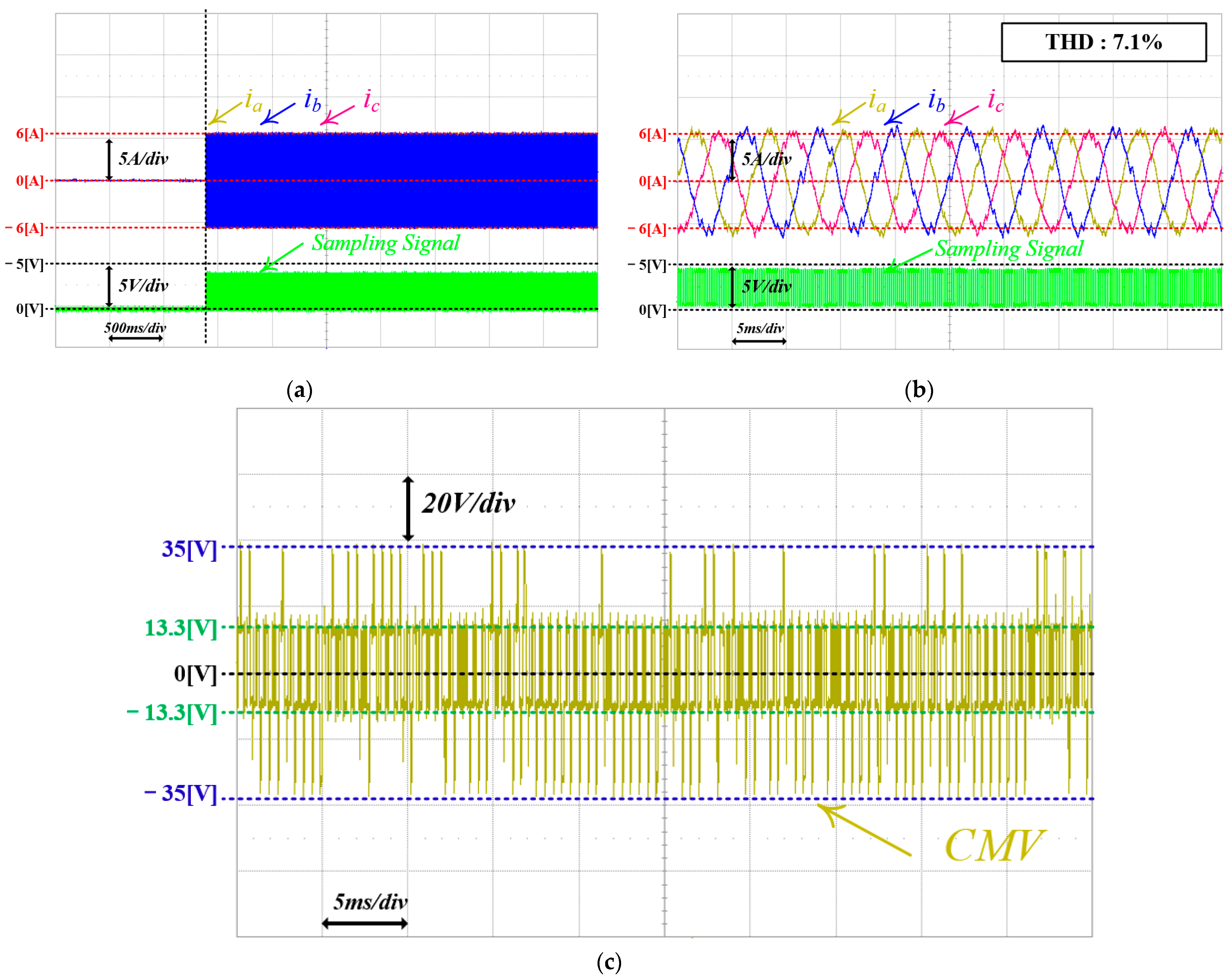
Figure 16 shows the experimental results for FCS-MPC, excluding the ZVV, in the reference VV synthesis. As shown in Figure 16b, which is an enlarged waveform of Figure 16a, this method excludes the selection of the ZVV in the reference VV synthesis process, resulting in larger current errors compared to the method that synthesizes using all VVs. Consequently, it exhibited a the load current THD of 7.1%, which was 1.7% higher than that of the FCS-MPC for current control. Figure 16c illustrates the CMV of the FCS-MPC excluding the ZVV. In comparison with Figure 15c, although fewer occurrences of peak CMV were visible owing to the exclusion of the ZVV in the command VV synthesis, the complete elimination of the peak CMV was not achieved, as it still includes cases with CMV during dead time intervals.

6.3. FCS-MPC Excluding ZVV with the Consideration of Dead Time Interval (Sampling Frequencies: 10 kHz, 20 kHz)

Figure 17 depicts the experimental results of FCS-MPC for CMV reduction using only non-ZVVs, considering dead time intervals, with a sampling frequency of 10 kHz. This approach synthesizes the reference VVs, excluding ZVVs. Additionally, by excluding the switching state transitions that cause the peak CMV during the dead time interval, the options for selecting future VVs were minimized to four. Therefore, as shown in Figure 17a, the THD of the load current is relatively high at 7.9%.
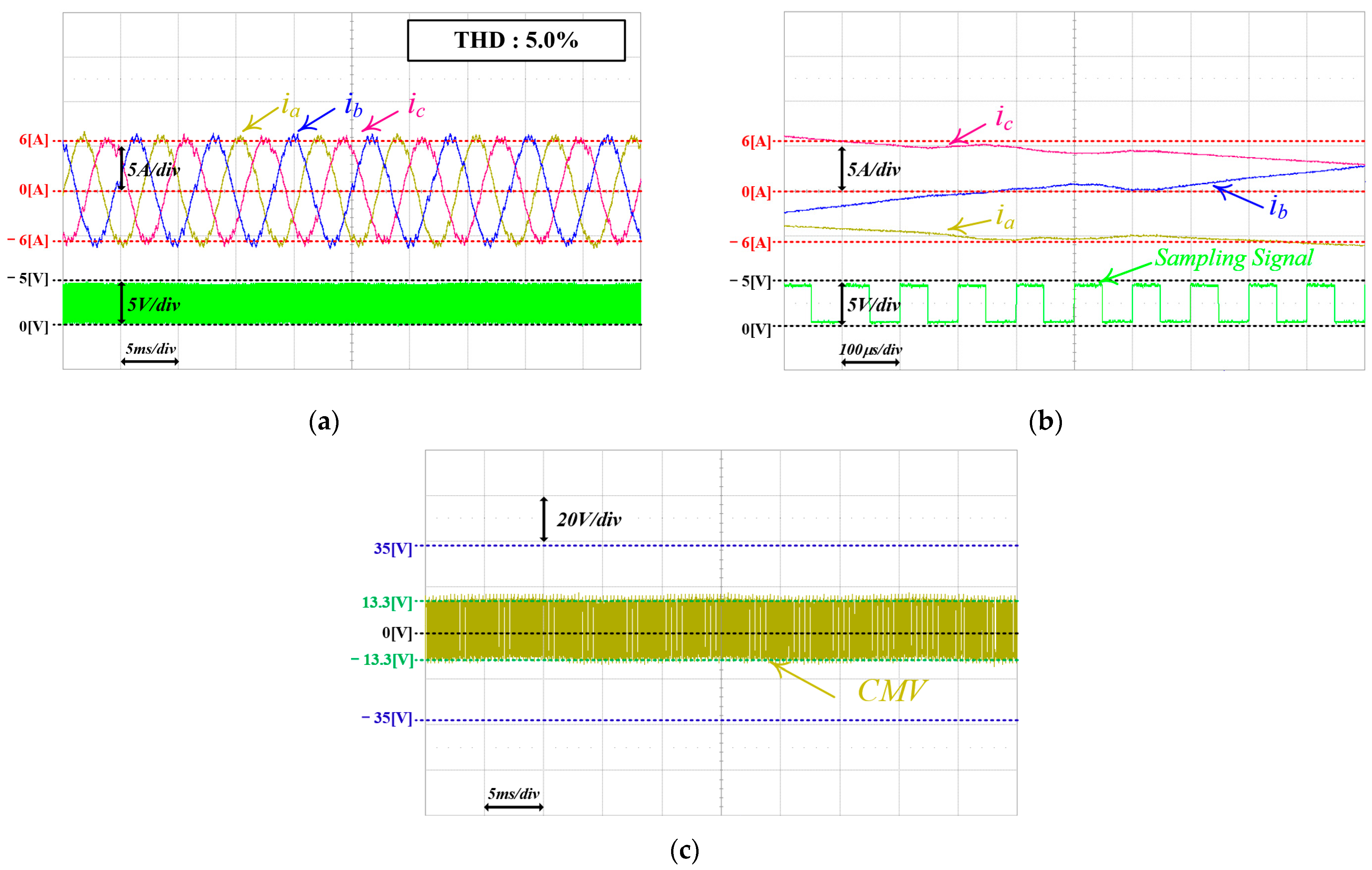
Figure 18 depicts the experimental results of the same FCS-MPC implementation as shown in Figure 17, but with an increased sampling frequency of 20 kHz. Compared to the case with a sampling frequency of 10 kHz, the THD of the load current decreased from 2.9% to 5.0%. However, this reduction was accompanied by an increase in CMV fluctuations and switching frequency.
All possible cases in which the CMV occurred were excluded from both sets of experiments presented in this subsection. Therefore, the CMV is always limited to approximately ±13.3 [V], rather than ±Vdc/2 or ±Vdc/6, ensuring that the CMV does not reach +Vdc/2 or −Vdc/2.

6.4. Proposed FCS-MPC for CMV Reduction with Variable Sampling Frequency

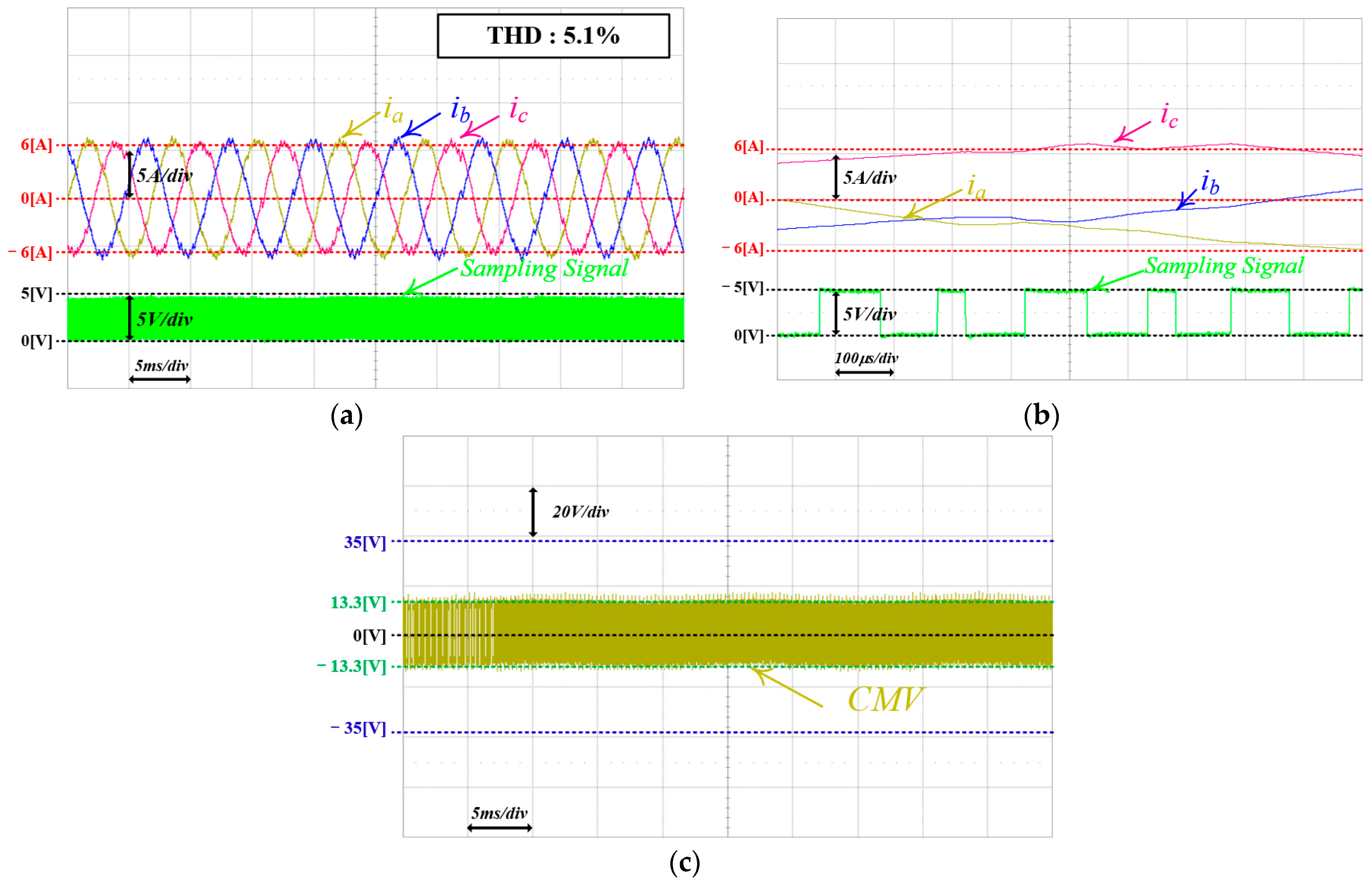
Figure 19 illustrates the experimental results of the FCS-MPC with the proposed variable sampling frequency for CMV reduction. As shown in Figure 19a, the proposed approach predicts and measures the points with the smallest current errors on the d-axis and q-axis, thereby ensuring a low THD. Consequently, the THD of the load current with the proposed approach was 5.1%, which is 2.8% lower than that shown in Figure 17a. In Figure 19b, though slightly higher by 0.1% compared to that in Figure 18a, the sampling period is variable between 50 and 100 [μs], and there are fewer switching than in Figure 18b. Moreover, to limit the CMV to within ±13.3 [V], the number of selectable future VVs was maintained at four. Thus, as shown in Figure 19c, applying the proposed method results in a maximum CMV of |±13.3| [V].
Figure 20 presents a comparison of the THD of the load currents for various FCS-MPC methods implemented through simulation and experimental results in this article. When compared to the FCS-MPC method for CMV reduction with a sampling frequency of 10 kHz, both in the simulation and experimental results, the THD of load currents with the proposed method decreased by over 2.8%. While the THD of the load currents slightly increased by approximately 0.1% compared to that of the FCS-MPC method for CMV reduction with a sampling frequency of 20 kHz, the switching state changes decreased from 92 to 76 per load current cycle.

7. Conclusions

This article proposes a variable sampling frequency-based FCS-MPC method with CMV reduction. For reference VV synthesis, both ZVV and VV transitions with the same circuit as the ZVV during the dead time interval were excluded. As a result, although the number of selectable future VVs decreased to four, it was possible to eliminate the peak CMV. Additionally, by confirming the intersection of the reference current and the predicted future current and deriving the point where the cost function composed of the d-axis and q-axis current errors is minimized, sampling is changed to that point. As shown in Table 4, this variable sampling compensates for the increase in the THD of the load current caused by the reduced options for the future VVs by up to 2.8% compared to a fixed sampling frequency of 10 kHz. Moreover, compared to a fixed sampling frequency of 20 kHz, it has a slightly higher load current THD, and the advantage of reducing the number of switching state changes by 16 per cycle of load current. The performance of the proposed FCS-MPC was validated by comparing it with the simulation and experimental results of conventional methods. The proposed method provides a good solution for reducing the current THD and minimizing the switching frequency.

Author Contributions

Conceptualization, Y.-S.L.; methodology, Y.-S.L. and K.-M.C.; software, Y.-S.L.; validation, Y.-S.L.; formal analysis, Y.-S.L. and K.-M.C.; investigation, Y.-S.L.; resources, C.-H.L.; data curation, Y.-S.L.; writing—original draft preparation, Y.-S.L.; writing—review and editing, Y.-S.L., K.-M.C. and C.-G.A.; visualization, Y.-S.L.; supervision, C.-Y.W. and J.Y.; funding acquisition, C.-H.L. and C.-Y.W. All authors have read and agreed to the published version of the manuscript.

Funding

This work was supported by the Railway Vehicle Parts Development Project of the Korea Agency for Infrastructure Technology Advancement (KAIA) funded by the Ministry of Land, Infrastructure and Transport of the Korean Government under grant RS-2020-KA1605663.

Data Availability Statement

Data is contained within the article.

Conflicts of Interest

Author Chang-Hee Lee was employed by the company Dawonsys Co., Ltd. The remaining authors declare that the research was conducted in the absence of any commercial or financial relationships that could be construed as a potential conflict of interest.

References

  1. Liang, D.; Li, J.; Qu, R.; Kong, W. Adaptive Second-Order Sliding-Mode Observer for PMSM Sensorless Control Considering VSI Nonlinearity. IEEE Trans. Power Electron. 2018, 33, 8994–9004. [Google Scholar] [CrossRef]
  2. Amin, M.M.; Mohammed, O.A. Development of High-Performance Grid-Connected Wind Energy Conversion System for Optimum Utilization of Variable Speed Wind Turbines. IEEE Trans. Sustain. Energy 2011, 2, 235–245. [Google Scholar] [CrossRef]
  3. Dheer, D.K.; Vijay, A.S.; Kulkarni, O.V.; Doolla, S. Improvement of Stability Margin of Droop-Based Islanded Microgrids by Cascading of Lead Compensators. IEEE Trans. Ind. Appl. 2019, 55, 3241–3251. [Google Scholar] [CrossRef]
  4. Jha, S.K.; Kumar, D.; Tripathi, P.R.; Samantaray, S.R.; Kamwa, I. Demand-Side Management of Self-Sustained Droop Based Standalone Microgrid Using Conservation Voltage Reduction Strategy. IEEE Syst. J. 2023, 17, 2640–2651. [Google Scholar] [CrossRef]
  5. Kumar, R.; Singh, B. Grid Interactive Solar PV-Based Water Pumping Using BLDC Motor Drive. IEEE Trans. Ind. Appl. 2019, 55, 5153–5165. [Google Scholar] [CrossRef]
  6. Han, D.; Peng, F.Z.; Dwari, S. Advanced PWM Techniques for Multi-Level Inverters with a Multi-Level Active CM Noise Filter. IEEE J. Emerg. Sel. Top. Power Electron. 2022, 10, 6865–6879. [Google Scholar] [CrossRef]
  7. Jeong, W.-S.; Lee, Y.-S.; Lee, J.-H.; Lee, C.-H.; Won, C.-Y. Space Vector Modulation (SVM)-Based Common-Mode Current (CMC) Reduction Method of H8 Inverter for Permanent Magnet Synchronous Motor (PMSM) Drives. Energies 2022, 15, 266. [Google Scholar] [CrossRef]
  8. Jeong, W.-S.; Kim, S.-H.; Yi, J.; Won, C.-Y. Finite Control Set–Model Predictive Control of H8 Inverter Considering Dead-Time Effect for PMSM Drive Systems with Reduced Conducted Common-Mode EMI and Current Distortions. IEEE Trans. Power Electron. 2022, 37, 5342–5356. [Google Scholar] [CrossRef]
  9. Hava, A.M.; Ün, E. Performance Analysis of Reduced Common-Mode Voltage PWM Methods and Comparison with Standard PWM Methods for Three-Phase Voltage-Source Inverters. IEEE Trans. Power Electron. 2009, 24, 241–252. [Google Scholar] [CrossRef]
  10. Kwak, S.; Mun, S. Common-mode voltage mitigation with a predictive control method considering dead time effects of three-phase voltage source inverters. IET Power Electron. 2015, 8, 1690–1700. [Google Scholar] [CrossRef]
  11. Ramírez, R.O.; Baier, C.R.; Espinoza, J.; Villarroel, F. Finite Control Set MPC with Fixed Switching Frequency Applied to a Grid Connected Single-Phase Cascade H-Bridge Inverter. Energies 2020, 13, 5475. [Google Scholar] [CrossRef]
  12. Rivera, M. Predictive current control for a VSI with reduced common mode voltage operating at fixed switching frequency. In Proceedings of the 2015 IEEE 24th International Symposium on Industrial Electronics (ISIE), Buzios, Brazil, 3–5 June 2015; pp. 980–985. [Google Scholar] [CrossRef]
  13. Guo, L.; Jin, N.; Gan, C.; Xu, L.; Wang, Q. An Improved Model Predictive Control Strategy to Reduce Common-Mode Voltage for Two-Level Voltage Source Inverters Considering Dead-Time Effects. IEEE Trans. Ind. Electron. 2019, 66, 3561–3572. [Google Scholar] [CrossRef]
  14. Karasala, C.; Panindra, K.V.; Kumar, A.P.; Ganjikunta, S.K. Model Predictive Control of PVGCI for Reducing Common Mode Voltage and Switching Frequency. IEEE J. Emerg. Sel. Top. Power Electron. 2023, 11, 3064–3075. [Google Scholar] [CrossRef]
  15. Kwak, S.; Mun, S.-K. Model Predictive Control Methods to Reduce Common-Mode Voltage for Three-Phase Voltage Source Inverters. IEEE Trans. Power Electron. 2015, 30, 5019–5035. [Google Scholar] [CrossRef]
  16. Hoseini, S.K.; Adabi, J.; Sheikholeslami, A. Predictive Modulation Schemes to Reduce Common-mode Voltage in Three-phase Inverters-fed AC Drive Systems. IET Power Electron. 2014, 7, 840–849. [Google Scholar] [CrossRef]
  17. Liu, Z.; Liu, J.; Li, J. Modeling, Analysis, and Mitigation of Load Neutral Point Voltage for Three-Phase Four-Leg Inverter. IEEE Trans. Ind. Electron. 2013, 60, 2010–2021. [Google Scholar] [CrossRef]
  18. Yang, Y.; Pan, J.; Wen, H.; Zhang, X.; Norambuena, M.; Xu, L.; Rodriguez, J. Computationally Efficient Model Predictive Control with Fixed Switching Frequency of Five-Level ANPC Converters. IEEE Trans. Ind. Electron. 2022, 69, 11903–11914. [Google Scholar] [CrossRef]
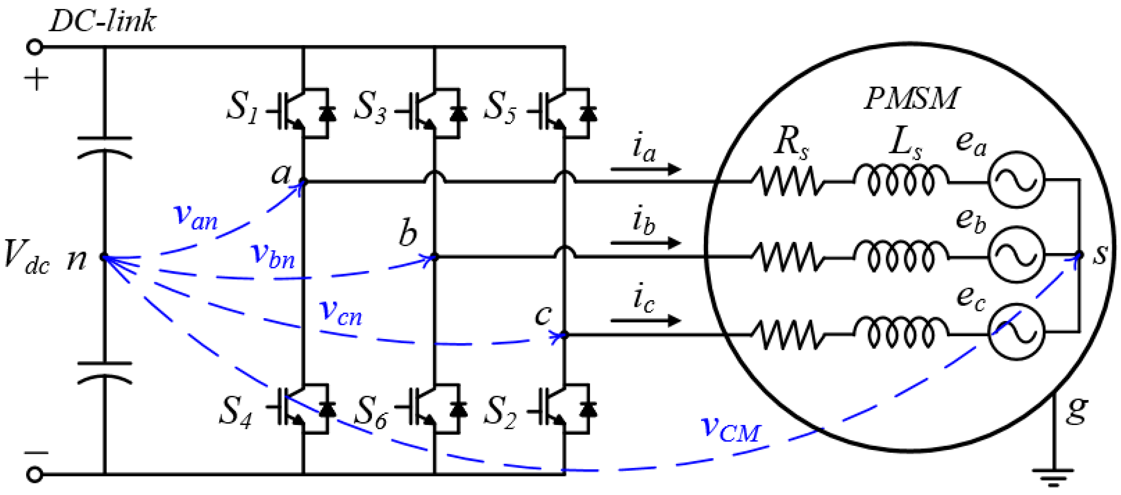
Figure 1. CMV in 2-level voltage source inverter.
Energies 17 01443 g001
Figure 2. Predicted d-axis and q-axis currents by VVs: (a) predicted d-axis currents and (b) predicted q-axis currents. * expresses the reference value.
Energies 17 01443 g002
Figure 3. Future predicted current applying ZVV and two non-ZVVs, respectively. * expresses the reference value.
Energies 17 01443 g003
Figure 4. FCS-MPC for reducing current ripple: (a) applying a high sampling frequency and (b) synthesizing two non-ZVVs within one sampling interval. * expresses the reference value.
Energies 17 01443 g004
Figure 5. VV transition where the switch state becomes V0 during the dead time: (a) circuit configuration for V1 and (b) circuit configuration for dead time interval between V1 and V3.
Energies 17 01443 g005
Figure 6. All the VV transitions with a CMV of V d c / 6 .
Energies 17 01443 g006
Figure 7. Cases where intersections between the predicted future current and the reference current are present and absent: (a) intersection absent and (b) intersection present.
Energies 17 01443 g007
Figure 8. Interval in which variable sampling can be applied.
Energies 17 01443 g008
Figure 9. FCS-MPC algorithm for CMV reduction with proposed variable sampling period.
Energies 17 01443 g009
Figure 10. Simulation results of FCS-MPC for current control with both ZVVs and non-ZVVs applied: (a) ia, ib, and ic; (b) magnified waveforms of (a); and (c) CMV.
Energies 17 01443 g010
Figure 11. Simulation results of FCS-MPC using only non-ZVVs: (a) ia, ib, and ic; (b) magnified waveforms of (a); and (c) CMV.
Energies 17 01443 g011
Figure 12. Simulation results of FCS-MPC using only non-ZVVs and considering the dead time interval: (a) simulation results with a sampling frequency of 10 kHz and (b) simulation results with a sampling frequency of 20 kHz.
Energies 17 01443 g012
Figure 13. Simulation results of FCS-MPC for CMV reduction with the proposed variable sampling frequency: (a) ia, ib, and ic; (b) magnified waveforms of (a); (c) CMV; and (d) sampling period.
Energies 17 01443 g013
Figure 14. Experiment equipment and 2L-VSI.
Energies 17 01443 g014
Figure 15. Experimental waveforms for FCS-MPC for current control: (a) ia, ib, ic, and sampling signal; (b) magnified waveforms of (a); and (c) CMV.
Energies 17 01443 g015
Figure 16. Experimental waveforms of FCS-MPC excluding ZVV: (a) ia, ib, ic, and sampling signal; (b) magnified waveforms of (a); and (c) CMV.
Energies 17 01443 g016
Figure 17. Experimental waveforms of FCS-MPC for CMV reduction using only non-ZVVs, considering dead time intervals (sampling frequency: 10 kHz): (a) ia, ib, ic, and sampling signal; (b) magnified waveforms of (a); and (c) CMV.
Energies 17 01443 g017
Figure 18. Experimental waveforms of FCS-MPC for CMV reduction using only non-ZVVs, considering dead time intervals (sampling frequency: 20 kHz): (a) ia, ib, ic, and sampling signal; (b) magnified waveforms of (a); and (c) CMV.
Energies 17 01443 g018
Figure 19. Experimental waveforms of the FCS-MPC with the proposed variable sampling frequency for CMV reduction: (a) ia, ib, ic, and sampling signal; (b) magnified waveforms of (a); and (c) CMV.
Energies 17 01443 g019
Figure 20. FCS-MPC algorithm for CMV reduction with proposed variable sampling time.
Energies 17 01443 g020
Table 1. CMV in 2L-VSI.
VVSwitching State (Sa, Sb, Sc) 1CMV Level
ZVVV0(0, 0, 0)Vdc/2
Non-ZVVV1(1, 0, 0)Vdc/6
V2(1, 1, 0)+Vdc/6
V3(0, 1, 0)Vdc/6
V4(0, 1, 1)+Vdc/6
V5(0, 0, 1)Vdc/6
V6(1, 0, 1)+Vdc/6
ZVVV7(1, 1, 1)+Vdc/2
1 Si(i = a,b,c) is a switching function that takes on the values “1” or “0”; if Sa = 1, the upper switch turns on and the lower switch has the complementary value.
Table 2. VV transitions that result in peak CMV during the dead time.
Present VVV1V2V3
Future VVV3, V5V4, V6V1, V5
Present VVV4V5V6
Future VVV2, V6V1, V3V2, V4
Table 3. Simulation parameters of proposed FCS-MPC method.
ParameterDescriptionValueUnit
VdcDC-Link Voltage70V
PrateRated Power1.1kW
ωrateRated Speed1500rpm
IrateRated Current9.5A
TrateRated Torque7.0Nm
pNumber of Poles24-
RsStator Resistance0.18Ω
LsStator Inductance3.4mH
Vpk/krpmPeak Line-to-Line Back EMF Constant43.5V/krpm
Table 4. Comparison between conventional and proposed methods.
MethodsCurrent ControlExcluding ZVVExcluding ZVV
and Considering Dead Time (10 kHz)
Excluding ZVV
and Considering Dead Time (20 kHz)
Variable Sampling Frequency
(Proposed)
THD of Load
Current
5.4%7.1%7.9%5.0%5.1%
Switching State Changes4647459276
Disclaimer/Publisher’s Note: The statements, opinions and data contained in all publications are solely those of the individual author(s) and contributor(s) and not of MDPI and/or the editor(s). MDPI and/or the editor(s) disclaim responsibility for any injury to people or property resulting from any ideas, methods, instructions or products referred to in the content.