Article

Induction Motor Improved Vector Control Using Predictive and Model-Free Algorithms Together with Homotopy-Based Feedback Linearization

1
Department of Automatic Control and Applied Informatics, “Gheorghe Asachi” Technical University of Iasi, 700050 Iasi, Romania
2
Department of Automatic Control and Electrical Engineering, “Dunarea de Jos” University of Galati, 800008 Galati, Romania
*
Author to whom correspondence should be addressed.
Energies 2024, 17(4), 875; https://doi.org/10.3390/en17040875
Submission received: 3 January 2024 / Revised: 27 January 2024 / Accepted: 5 February 2024 / Published: 14 February 2024
(This article belongs to the Special Issue Advanced Control in Power Electronics, Drives and Generators)

Abstract

:
Vector control of an induction machine (IM) is typically performed by using cascade control structures with conventional linear proportional–integral (PI) controllers, the inner loop being designed for current control and the outer loop for rotor flux and speed control. In this paper, starting with the dq model of the IM, advanced control algorithms are proposed for the two control loops of the cascade structure. For the current inner loop, after the decoupling of the two dq currents, predictive control algorithms are employed to independently control the currents, considering the constraints imposed by the electrical signal physics limitations. Since the outer loop has a nonlinear affine multivariable plant model, a homotopy-based variant of feedback linearization is used to obtain a nonsingular decoupling matrix of the feedback transformation even when the rotor flux is zero at the start-up of the motor. During the continuous variation in the homotopy parameter, the plant model is variable and, for this reason, model-free algorithms are used to control the flux and speed of the IM due to their capabilities to manage complex dynamics from data without requiring knowledge of the plant model. The performances of the proposed cascade control strategy with advanced algorithms in the two loops were tested by simulation and compared with those obtained with conventional PI controllers, resulting in better dynamic behavior for predictive and model-free control.

1. Introduction

The progress made in recent decades in the field of power electronics and computer technology has resulted in the induction motor (IM) being used in high-performance drives. Due to its simplicity, low cost, and reliability, the IM is preferred in industrial applications. However, its nonlinear dynamics with internal coupled states involve appropriate advanced control strategies to achieve the requirement of high performance.
The classical advanced control structure of the IM is traditionally designed in cascade topology, where the vector control principle, also called field-orientated control (FOC), is used [1,2,3].
The vector control strategy is based on the dynamic dq model of the IM defined in the synchronously rotating reference frame. Usually, the inner loop is intended for dq stator currents control and the outer one is used for rotor flux and rotor mechanical speed control. Due to the nonlinear, multivariable coupled models of the two loop plants, various control techniques have been developed to solve the problems generated by complex models.
For the inner loop, model linearization and its decoupling through feedforward components are generally used. Based on the resulting decoupled linear models, the dq stator currents are usually controlled with two proportional–integral (PI) controllers [3,4]. Due to the physics-based constraints generated by the limits imposed on the stator voltages and currents, PI control has been replaced with advanced techniques to solve this problem. In general, among the advanced techniques used for the inner loop, model predictive current control (MPCC) algorithms are preferred because constraints due to the physical limitations of the stator voltages and currents can be imposed in the design phase. However, in most cases, MPCC is based on the multivariable coupled nonlinear model of dq currents, resulting in the two currents not being separately controlled, according to the FOC requirement. Thus, in [5], two model predictive control (MPC) cascade structures based on a continuous control set and finite control set without PI controllers were analyzed, studying the advantages and difficulties. The inner loop generates the output control voltages, considering the stator voltages and current constraints, and the outer loop is the torque reference, keeping in mind the constraints of the torque/speed characteristics of the IM. The full predictive cascaded speed and current control of an IM is presented in [6]. Here, the currents from the inner loop are controlled using a finite control set MPC algorithm, while, for speed control, a continuous control set MPC based on the explicit inversion of the mechanical model is suggested. Considering the importance of the handling of constraints for induction machines, in [7], a cascade speed control structure with MPC controllers capable of incorporating the constraints in the objective function is proposed. The inner loop uses an MPCC controller, and the outer one uses an explicit MPC controller for speed control. The common limitations of the stator voltages and currents described as quadratic inequality in the dq-frame are reformulated because the quadratic inequalities of the current and voltage can be represented by the linear one of the torque. The linear inequality is parameter-varying because the limited torque depends nonlinearly on the rotor speed and, to solve this problem, a multiparametric quadratic programming (mp-QP) algorithm is utilized. To replace the inner PI current controllers and the pulse width modulation (PWM) block and, thus, to obtain faster dynamics, in [8], a finite control set predictive current control approach is proposed to control the IM. For rotor speed control, in the outer loop, a PI controller is used and, for IM stator windings protection, the electromagnetic torque current command is limited. By including the magnetic saturation and rotor-speed-dependent iron-loss resistance in the IM model, in [9], an MPCC strategy is developed based on this model for IM control considering saturation and iron core losses, to which a control effort penalty is added to reduce the average switching frequency. The proposed strategy is based on replacing the PI current controllers in the inner loop with the proposed predictive control algorithm, while, in the outer loop, a classical PI controller is used to control the mechanical speed of the rotor. But there are also IM control structures that keep PI controllers in the inner loop. Thus, for the cascade control structure in [10], a multivariable generalized predictive control (GPC) controller is proposed for rotor speed and flux control, while, in the inner loop, the currents are controlled with conventional PI controllers. The stator is protected against over electrical signals by the current constraints imposed on the GPC controllers in the design phase and by restricting the module of the phase stator voltage through a limiting block attached to the PI controllers.
For the outer loop, the two controlled currents of the inner loop are used as inputs so that the d component keeps the rotor flux constant as well as the q one to control rotor speed. The main problem of outer loop control derives from the nonlinear coupled multivariable model of the plant. In the vector control approach, with the assumption that the rotor flux is constant after reaching its reference, the speed dynamics become linear and can be controlled with PI controllers [11]. One method to decouple the flux dynamics from the speed dynamics is to use the input–output feedback linearization method, which leads to separating the flux and speed control. But the input–output feedback linearization method cannot be applied to the IM model due to the singularity of the decoupling matrix of the feedback transformation when the flux is zero at the start-up of the motor [4,12]. To solve this problem, in [11], based on an IM model which includes both electrical and mechanical dynamics, it is proposed to control the square of the rotor flux and the speed using the input–output linearization technique in conjunction with the use of an open loop controller at the start-up of the motor. As soon as the flux becomes greater than zero, the control input is switched from the open loop controller to the nonlinear-state feedback control. Starting from the same reduced fourth-order state-space model of the IM and the control objectives from [11], in [13], a switching strategy based on the homotopy continuation is presented that allows the application of the input–output feedback linearization approach. The strategy is based on the construction of a homotopy that combines the output of the nonlinear model of the IM with the output of an attached linear model, which is then linearized by feedback. When the conventional feedback linearization cannot be applied, the control is switched to the parameter continuation method. Starting from [13], the authors presented in [4] a new control approach for driving the output to zero using the combination of the state feedback linearization and the homotopy numerical continuation, which does not require switching between two computationally complex controllers. Both methods from [4,13] use a cascade control structure with a PI current control inner loop, but the outer loop from [13] controls the square of the flux and the speed, while, in [4], the deviation of the flux and speed is in relation with their references. Another method for dynamic feedback linearization control of an IM is presented in [14], where, to avoid the impossibility of applying linearization through feedback, an integrator on the d-axis is additionally added to the IM dq model and, thus, the decoupling matrix of the feedback transformation is no longer singular at the start-up of the motor. The dq currents are controlled in an inner loop using conventional PI controllers. The introduction of an integrator on the q-axis instead of the d-axis is also analyzed, resulting in the feedback linearization of the IM model but with the disadvantage that the feedback controller is singular when the quadrature current is zero and implicitly the motor torque is zero. A speed/position control strategy for the IM based on the exact feedback linearization with state and state-derivative feedback is presented in [15]. This control strategy also uses PI controllers for the current loop. IM speed sensorless feedback linearization control based on a current/flux and speed tracking controller is proposed in [16]. Using a cascade control structure, the feedback linearization controller is designed to control the inner current loop and, respectively, the speed and flux in the outer loop. To obtain speed tracking throughout the operating range, a PI controller is added. Also, using an input–output feedback linearization technique, in [17], a sliding-mode speed controller for the IM is proposed instead of the classical PI.
The MPCC algorithms for the inner loop mentioned above, although they handle the physics constraints more easily, being designed considering the uncoupled multivariable model of the dq currents, do not fulfill the major requirement of the FOC regarding the independent control of the two currents. For the outer loop, the above methods for decoupling the flux from the rotor speed through feedback linearization require an additional loop to track the imposed references. Typically, the additional loop uses PI controllers, which do not always give good transient dynamics, especially if the homotopy variant of the feedback linearization is used.
In this paper, to solve the aforementioned problems, a new cascade control structure is proposed for the speed and flux control of an IM. For dq current control, in the inner loop, decoupling and MPCC algorithms are used. In the outer loop, its plant is firstly linearized and decoupled by feedback based on the homotopy continuation and, then, the model-free intelligent-proportional (iP) algorithms are employed so that the two controlled outputs track the related references. In the inner loop, the cross-coupling of the dq currents and the back electromotive force (EMF) are considered disturbances that are compensated by a decoupling algorithm based on feedforward components. After decoupling, two linear single-input single-output (SISO) models result, which are used to design the MPCC algorithms, taking into account the physics constraints introduced by the limitations imposed on the stator currents and voltages. To reduce the computational effort of the constraint optimization, a boxed linear constraint [3] was used, with the consideration of the relationships between the dq stator voltages generated by MPCC controllers via the decoupling algorithm. In the outer loop, to decouple the flux from the rotor speed and, thus, control them independently, the homotopy-based variant of the feedback linearization from [4] was utilized. Since, at the beginning, when the homotopy parameter varies between zero and one, the plant model is variable, a model-free iP controller is proposed for the additional loop used to control the flux and speed of the IM due to their capabilities to manage complex dynamics from data, without requiring the knowledge of the plant model. This employment of the SISO box constrained MPCC algorithms, together with the homotopy-based variant of feedback linearization and model-free iP algorithms led to IM improved vector control compared to the use of conventional PI controllers instead of advanced algorithms. The performances of the proposed cascade control strategy were tested by simulation and compared with those obtained with conventional PI controllers, resulting in a better dynamic behavior for the predictive and model-free control. The following are the major contributions of this paper:
Incorporating MPCC and model-free advanced algorithms together with the homotopy-based feedback linearization to IM improved vector control.
To reduce the computational effort of the constrained optimization, our method uses a boxed linear constraint for considering the physics limitations of the stator currents and voltages.
To solve the limitation related to the stator voltages, we developed a method by which the limitations were correlated with the outputs of the MPCC controllers and with the feedforward components of the decoupling algorithm.
To solve the reference tracking problem in conjunction with the feedback linearization, we used a model-free algorithm due to the modeling uncertainty during the variation of the homotopy parameter from zero to one.
To demonstrate the ability to improve the vector control of the IM with the proposed cascade control structure that includes advanced algorithms, a case study was performed.
The paper is organized as follows. Section 2 presents the dq IM nonlinear model for the vector control strategy. Section 3 is dedicated to the IM cascade control structure design, considering a constrained predictive current control algorithm for the inner loop and a homotopy-based variant of feedback linearization for the outer loop plant together with the model-free control algorithms for the rotor flux and speed control. An illustrative case study is given in Section 4 that presents a comparative analysis of the results obtained for both the conventional controllers and the advanced ones. At last, in Section 5 the main features arising from the study developed in this paper are summarized.

2. Nonlinear IM Model for Vector Control

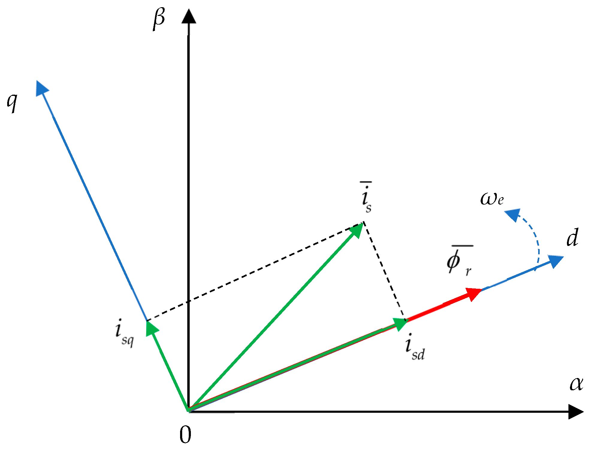
IM control is typically carried out by using the vector control strategy, which can separate the stator current components that produce the rotor flux and the electromagnetic torque, respectively. Thus, the well-known vector control strategy of the IM is usually performed in the reference frame dq attached to the rotor flux space vector whose direct d-axis is aligned with the rotor flux space vector ϕ ¯ r , as shown in Figure 1.
Besides the stationary frame αβ fixed to the stator, the stator current space vector i ¯ s has the components i s d ,   i s q in the reference frame dq attached to the rotor, which rotates at a general speed ω e . This alignment of the rotor flux space vector ϕ ¯ r with the d-axis causes the q-axis component to be zero [11,18], resulting in the dq flux components:
ϕ r d = ϕ d ϕ r q = 0 ,   d ϕ r q d t = 0 .
The IM model, represented in dq co-ordinates, includes stator current equations, rotor flux, and motion equations [11]:
d i s d d t = 1 τ 1 i s d + ω s i s q + β τ r ϕ r + 1 L 1 u s d d i s q d t = ω s i s d 1 τ 1 i s q β ω e ϕ r + 1 L 1 u s q ,
d ϕ r d t = 1 τ r ϕ r + L m τ r i s d ,
d ω m d t = ( T e T r ) / J ,
where ( u s d , u s q ) and ( i s d , i s q ) represent the components of the stator voltages and currents in the dq reference frame, ϕ r is the rotor flux, ω s denotes the synchronous angular speed, ( ω e , ω m ) are the electrical and mechanical rotor angular speeds correlated by ω m = ω e / p , where p is the number of pole pairs, T e and T r are the electromagnetic and load torques, and J is the motor inertia. The parameters and the time constants related to the model described by Equations (2)–(4) are given by:
R 1 = R s + R r ( L m / L r ) ;   L 1 = L s L m 2 / L r ;   β = L m / ( L r L 1 ) ;   τ 1 = L 1 / R 1 ;   τ r = L r / R r ,
where ( R s , R r ) represent the stator and rotor resistances,   ( L s , L r ) are the stator and rotor self-inductances, L m is the mutual inductance, R 1 is the equivalent resistance and L 1 the equivalent inductance, τ 1 is the equivalent time constant, τ r is the rotor time constant, and β is a constant.
The synchronous angular speed ω s from Equation (2) is estimated using:
ω s = ω e + L m τ r i s q ϕ r ,
and the electromagnetic torque T e from Equation (4) is calculated with:
T e = p L m L r ϕ r i s q .
Analyzing the IM model from Equations (2)–(7), it turns out that it is a strongly nonlinear coupled multivariable system.
The rotor flux-oriented vector control strategy requires the independent control of the two currents: i s d , which produces the rotor flux, and i s q , which generates the electromagnetic torque, respectively. The control of the two currents is performed by the stator voltages u s d and u s q , which are not decoupled control variables, as can be seen from Equation (2). To decouple and independently control the two stator currents i s d / q , the stator voltage equations must be decoupled. The interactions between the stator currents and the nonlinearity of the current system are eliminated commonly using feedforward components. The control and decoupling of the stator currents is usually carried out in an inner loop of a cascade control structure considering the constraints generated by the physics electrical signal limits. In the outer loop, the rotor flux ϕ r and the mechanical rotor angular speed ω m are controlled based on the affine nonlinear multivariable system generated by Equations (3) and (4) and using as control variables the current references i s d r e f and i s q r e f . To obtain a linear decoupled behavior between the inputs and outputs of the outer plant model, a feedback linearization strategy can be used.
To solve the control problems mentioned above, generated by the nonlinear IM model, this paper proposes a cascade control strategy with the inner loop for the independent control of the currents and the outer loop for the independent control of the rotor flux and speed. A detailed presentation of the cascade control structure, together with its design, are given in the next section.

3. IM Cascade Control Structure Design

The cascade control structure proposed for the vector control of an IM consists of an inner loop, designed to control the dq currents with decoupling and predictive control algorithms, and an outer loop, which, after applying a homotopy-based variant feedback linearization for the nonlinear loop plant, is designed to independently control the rotor flux and speed with model-free algorithms.
In what follows, the design of the two control loops of the proposed cascade control structure with advanced control algorithms is presented.

3.1. Inner Loop Design

The current model, Equation (2), has a multivariable nonlinear structure, with a strong coupling between the dq axes.

3.1.1. Decoupling Algorithm

Since the stator currents i s d / q must be independently controlled, according to the vector control requirements, it is necessary to decouple them. In this context, the current model in Equation (2) is rewritten as follows, considering:
u s d = L 1 d i s d d t + R 1 i s d L 1 ω s i s q L 1 β τ r ϕ r = v s d + u s d p , u s q = L 1 d i s q d t + R 1 i s d + L 1 ω s i s d + L 1 β ω e ϕ r = v s q + u s q p . R L   eqv .   circuit coupling   and   back   EMF
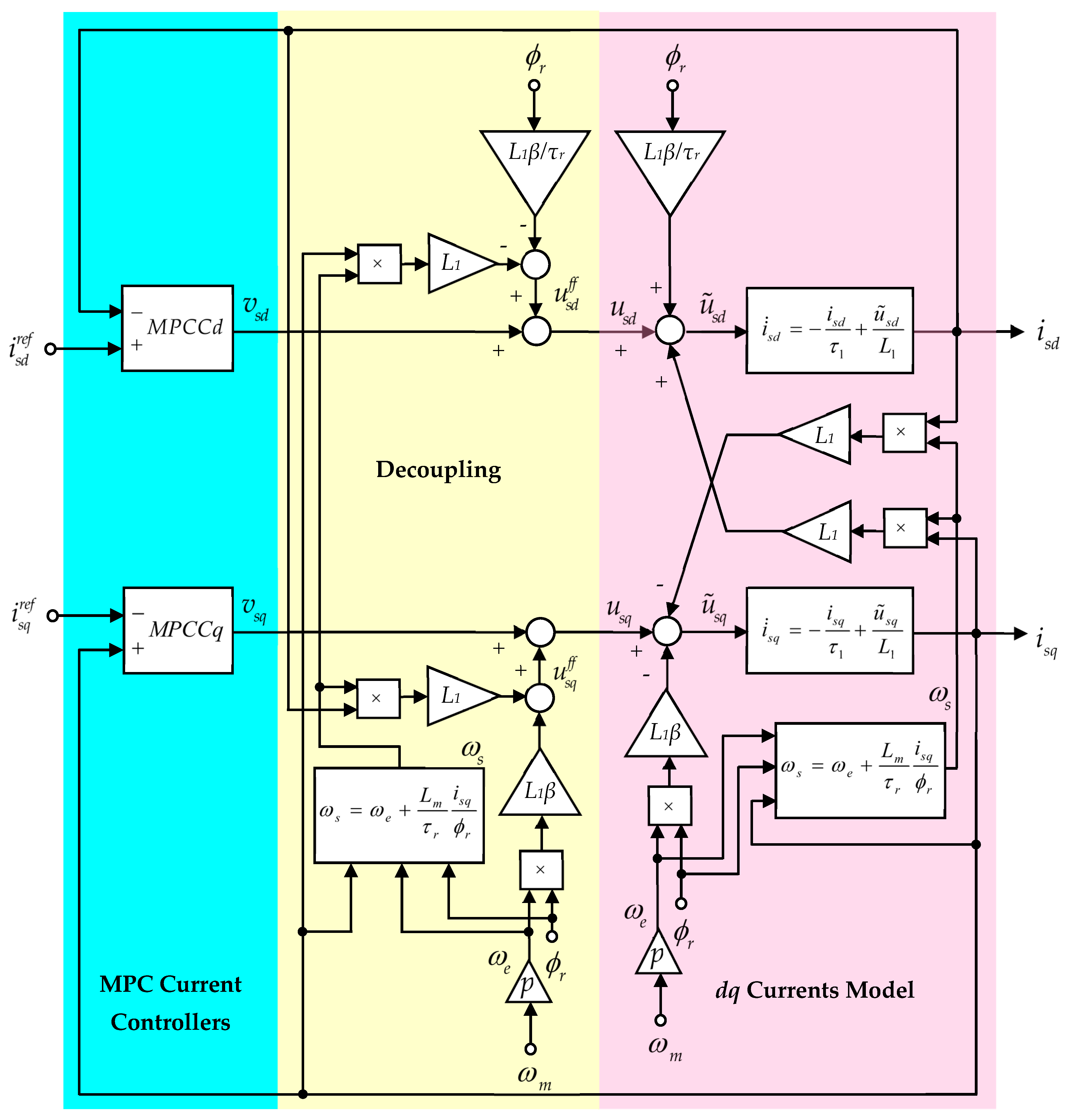
Thus, two components of the stator voltages u s d / q are highlighted, one linear v d / q correlated with an RL equivalent circuit and another u s d / q p , which is generated by the cross-coupling and back EMF. The linear voltage components v s d / q represent the controller outputs that control the currents i s d / q and the voltage components u s d / q p are considered disturbances that must be compensated by a decoupling algorithm based on feedforward components. To decouple the stator voltage from Equation (8), the feedforward components u d / q f f are used, resulting in:
u s d = v s d + u s d f f u s q = v s q + u s q f f ,
where the feedforward components are:
u s d f f = L 1 ω s i s q L 1 β τ r ϕ r ,
u s q f f = L 1 ω s i s d + L 1 β ω e ϕ r .
Using the above decoupling procedure based on feedforward, the coupled multivariable nonlinear model of the currents in Equation (8) is transformed into two identical SISO linear models for the two currents:
L 1 d i s d / q d t + R 1 i s d / q = v s d / q .

3.1.2. Constraint Formulation

In addition, for stator current control, the physics limitations imposed on the currents i s d / q and voltages u s d / q must be considered to prevent IM damage. Thus, the two components of the dq currents and voltages must satisfy the limitations:
i s d 2 + i s q 2 I s m a x u s d 2 + u s q 2 U s m a x ,
where the maximum value of the stator current I s m a x is chosen to be correlated with the nominal value I s N of the stator current and, considering the DC-bus voltage V D C , the maximum value of the stator voltages is U s m a x = V D C / 3 . Since the constraint Equations (13) are quadratic functions, to simplify the computation of the constrained optimization, a boxed linear constraint [3] that approximates the circular area with a rectangular one will be used. The box constraints for the i s d / q  stator currents are defined by finding a parameter, 0 ≤ γ c ≤ 1, so that:
i s d m a x = γ c I s m a x ,
and, from here:
i s q m a x = 1 γ c 2 I s m a x .
The stator current i s d , which generates the rotor flux ϕ r , varies in the interval i s d [ 0 ,   i s d N ] , where the nominal value i s d N is obtained from Equation (3) in a steady state, resulting in:
i s d N = ϕ r N L m .
where ϕ r N is the nominal value of the rotor flux.
Since the maximum value i s d m a x is the nominal value i s d N , from Equations (14) and (16), the expression of the γ c parameter is as follows:
γ c = ϕ r N L m I s m a x .
With the maximum values given by Equations (15) and (16), the currents’ box constraints become:
0 i s d i s d m a x = i s d N i s q m a x i s q i s q m a x .
Similarly, for the u s d / q stator voltages, a parameter 0 γ v 1 is chosen to calculate the maximum values:
u s d m a x = γ v V D C / 3   u s q m a x = 1 γ v 2 V D C / 3 ,
and, then, the voltage box constraints are obtained:
u s d m a x u s d u s d m a x u s q m a x u s q u s q m a x .
Limiting the stator voltages u s d / q can be conducted by limiting the outputs v s d / q of the current controllers using Equation (9), as follows:
v s d m a x = u s d m a x u s d f f m a x v s q m a x = u s q m a x u s q f f m a x .
The maximum value u s d / q f f m a x of the feedforward components is determined using Equations (10) and (11) and considering the maximum values of the stator voltages u s d / q m a x specified by Equation (19), the nominal values of the angular velocities ω s N and ω e N , the nominal value of the rotor flux ϕ r N , and the maximum values i s d / q m a x for the currents given by Equations (14) and (15). Taking into account these assumptions, the maximum values of the current controller outputs will be:
v s d m a x = γ v V D C / 3 L 1 ω s N 1 γ c 2 I s m a x L 1 β τ r ϕ r N v s q m a x = 1 γ v 2 V D C / 3 + γ c I s m a x + L 1 β ω e N ϕ r N ,
and, thus, the box constraints for the voltages v s d / q are obtained:
v s d m a x v s d v s d m a x v s q m a x v s q v s q m a x .
Considering the above constraints imposed to the stator currents and voltages in the dq-frame, MPCC controllers were chosen to control the currents i s d / q based on the model in Equation (12).

3.1.3. MPCC Controller Design

The design of the MPCC controller is conducted using the discrete model of the two currents obtained from Equation (12) by discretization with the sample period Ts. Considering that the parameters of the model in Equation (12) are identical for the two currents, the following discrete model was obtained:
i s j ( k + 1 ) = a i s j ( k ) + b v s j ( k ) , j = d , q .
For reference tracking, a new state x c ( k ) = v s j ( k 1 ) is introduced in Equation (24) to have as input the increment Δ v s j ( k ) = v s j ( k ) v s j ( k 1 ) , resulting in the augmented current discrete model, which incorporates an integral action:
[ i s j ( k + 1 ) x c ( k + 1 ) ] x j ( k + 1 ) = [ a b 0 1 ] Φ [ i s j ( k ) x c ( k ) ] x j ( k ) + [ b 1 ] γ Δ v s j ( k ) x j ( k + 1 ) = Φ x j ( k ) + γ Δ v s j ( k ) .
Based on the one-step-ahead prediction given by Equation (25), the predictions for the augmented model are recursively found, as follows:
x j ( k + n | k ) = Φ n x j ( k ) + s = 0 n 1 Φ s γ Δ v j ( k 1 s ) ,
where x j ( k + n | k ) denotes the value predicted at the discrete time k.
To design the MPCC controller based on the model in Equation (25) and considering the bounded outputs and inputs, the following quadratic cost function from [19] is used:
J j ( V j ) = n = 1 h p ( δ j n ( i s j ( k + n | k ) i s j r e f ( k ) ) ) 2 + p = 0 h c ( μ j p Δ v s j ( k + p | k ) ) 2 + ρ j ε ε j s . t . { j = d { 0 ε d W d i s d m i n i s d ( k + n | k ) i s d m a x + ε d W d i s d m a x , n = 1 , , h p v s d m a x ε d W d v s d m i n v s d ( k + p | k ) v s d m a x + ε d W d v s d m a x ,   p = 0 , , h c 1 j = q { i s q m a x ε q W q i s q m i n i s q ( k + n | k ) i s q m a x + ε q W q i s q m a x , n = 1 , , h p v s q m a x ε q W q v s q m i n v s q ( k + p | k ) v s q m a x + ε q W q v s q m a x ,   p = 0 , , h c 1 ,
where hp and hc are the prediction and control horizons, δ j n and μ j p are the output and control weights, V j = { Δ v s j ( k | k ) ,   Δ v s j ( k + 1 | k ) ,   ,   Δ v s j ( k + h c 1 | k ) ,   ε j } is the future control sequence, ε j is the slake variable introduced for obtaining soft constraints, and ρ j ε is the weight of the slake variable. The violation multipliers W j * vary continuously between 0 and 1; for W j * = 0 hard constraints are obtained; otherwise, soft constraints.
The output prediction can be obtained from Equation (26):
i s j ( k + n | k ) = [ 1 0 ] x j ( k + n | k ) .
Substituting the output prediction in Equation (28) into Equation (27), the cost function minimization is formulated as a quadratic programing (QP) problem:
V j * = arg m i n V j ( 1 2 V T M V + [ i s j ( k ) i s j r e f ( k ) v s j ( k 1 ) ] N T V ) s . t . :   G V W + S [ i s j ( k ) i s j r e f ( k ) v s j ( k 1 ) ] ,
where the optimal solution is:
V j * = [ Δ v s j * ( k | k )   Δ v s j * ( k + 1 | k ) ,   ,   Δ v s j ( k + h c 1 | k ) ,   ε j * ] T ,
and the matrices of appropriate dimensions M, N, G, W, and S have the expressions from [20,21].
Applying the receding horizon principle, only the first element of V j * is further used to obtain the MPCC control law:
v j ( k ) = v j ( k 1 ) + Δ v j * ( k ) .
The predictive currents control structure from the inner loop is represented in Figure 2.

3.2. Outer Loop Design

The inner loop intended to control the dq currents has a very fast dynamic compared to the rotor flux and the mechanical angular speed described by Equations (3) and (4). In this context, the currents reach the imposed references extremely quickly, and it can be considered i s d / q i s d / q r e f and, thus, the related outer loop plant is described only by Equations (3) and (4), which generates the following coupled nonlinear affine system:
[ ϕ ˙ r ω ˙ m ] x ˙ = [ 1 τ r ϕ r 0 ] f ( x ) + [ L m τ r 0 0 p L m J L r ϕ r ] g ( x ) [ i s d i s q ] i s d / q { x ˙ = f ( x ) + g ( x ) i s d / q y = x .
To achieve the decoupling of the rotor flux and angular speed dynamics, a common method is the use of input–output feedback linearization.
The nonlinear affine model in Equation (32) cannot be linearized by feedback because the input–output decoupling matrix is singular at the motor start-up when the rotor flux ϕ r is zero.
To use the feedback linearization method, an open loop controller at start-up can be employed [11] or a homotopy-based variant of feedback linearization as in [4], the last approach being employed in this paper.

3.2.1. Homotopy-Based Feedback Linearization

To apply the feedback linearization method based on homotopy continuation to the irregular affine system in Equation (32) with ill-defined relative degree, firstly, the controlled outputs are considered the deviations of the system (32) outputs from their references:
[ d ϕ d ω ] = [ ϕ r ϕ r r e f ω m ω m r e f ] .
Applying the first differentiation to the output d = [ d ϕ d ω ] T , the same model in Equation (32) is obtained:
{ d ˙ = f ( x ) + g ( x ) i s d / q y = d ,
with [ d ˙ ϕ d ˙ ω ] T = [ ϕ ˙ r ω ˙ m ] T . The new model with the outputs d φ and d ω cannot be linearized by feedback due to its ill-defined relative degree generated by ϕ r = 0 . To solve the problem, the following linear dynamic system is associated with the outer loop plant model in Equation (34):
[ η ˙ d η ˙ q ] = [ 1 0 0 1 ] [ i s d i s q ]   with   η ( 0 ) = [ 0 0 ] .
Using the outputs d and η of the two associated systems, a new output is constructed [4]:
H = ( 1 λ ) η + λ d ,
where the influence of the outputs d and η to the new output H is determined by the continuous time-dependent parameter λ [ 0 , 1 ] . For λ = 0 , the output of the linear model is obtained, which is continuously deformed into the output of the nonlinear model when λ = 1 .
For the new augmented system, a controller will be determined through feedback linearization to ensure a linear dynamic. Applying the first differentiation to the output H = [ h ϕ h ω ] T , we obtain:
[ h ˙ ϕ h ˙ ω ] = λ [ d ˙ ϕ d ˙ ω ] + ( 1 λ ) [ i s d i s q ] + λ ˙ [ d ϕ η d d ω η q ] .
Since [ d ˙ ϕ d ˙ ω ] T = [ ϕ ˙ r ω ˙ m ] T , substituting into Equation (36) the expressions of ϕ ˙ r and ω ˙ m from Equation (32), we obtain:
[ h ˙ ϕ h ˙ ω ] = λ [ ϕ r / τ r + L m i s d / τ r p L m ϕ r i s q / J L r ] + ( 1 λ ) [ i s d i s q ] + λ ˙ [ d ϕ η d d ω η q ] .
Grouping in a vector the currents i s d and i s q together with λ ˙ , Equation (38) becomes:
[ h ˙ ϕ h ˙ ω ] = [ λ L m / τ r + 1 λ 0 d ϕ η d 0 λ p L m ϕ r / J L r + 1 λ d ω η q ] A [ i s d i s q λ ˙ ] + [ λ ϕ r / τ r 0 ] B .
For the augmented system in Equation (39), in [4], it is proved that the state feedback equation:
[ i s d i s q λ ˙ ] = α τ + A + ( m B ) ,
exists and the nonlinear feedback in Equation (40) transforms the nonlinear system in Equation (38) into the linear system:
[ h ˙ ϕ h ˙ ω ] = [ m d m q ] ,
which can be controlled with algorithms related to linear systems. In Equation (40), α R + is a constant, A + is the Moore–Penrose inverse matrix of A, and the vector τ is chosen to fulfill the constraints [4]:
A τ = 0 ,   τ 2 = 1 ,   det ( A τ T ) > 0 .
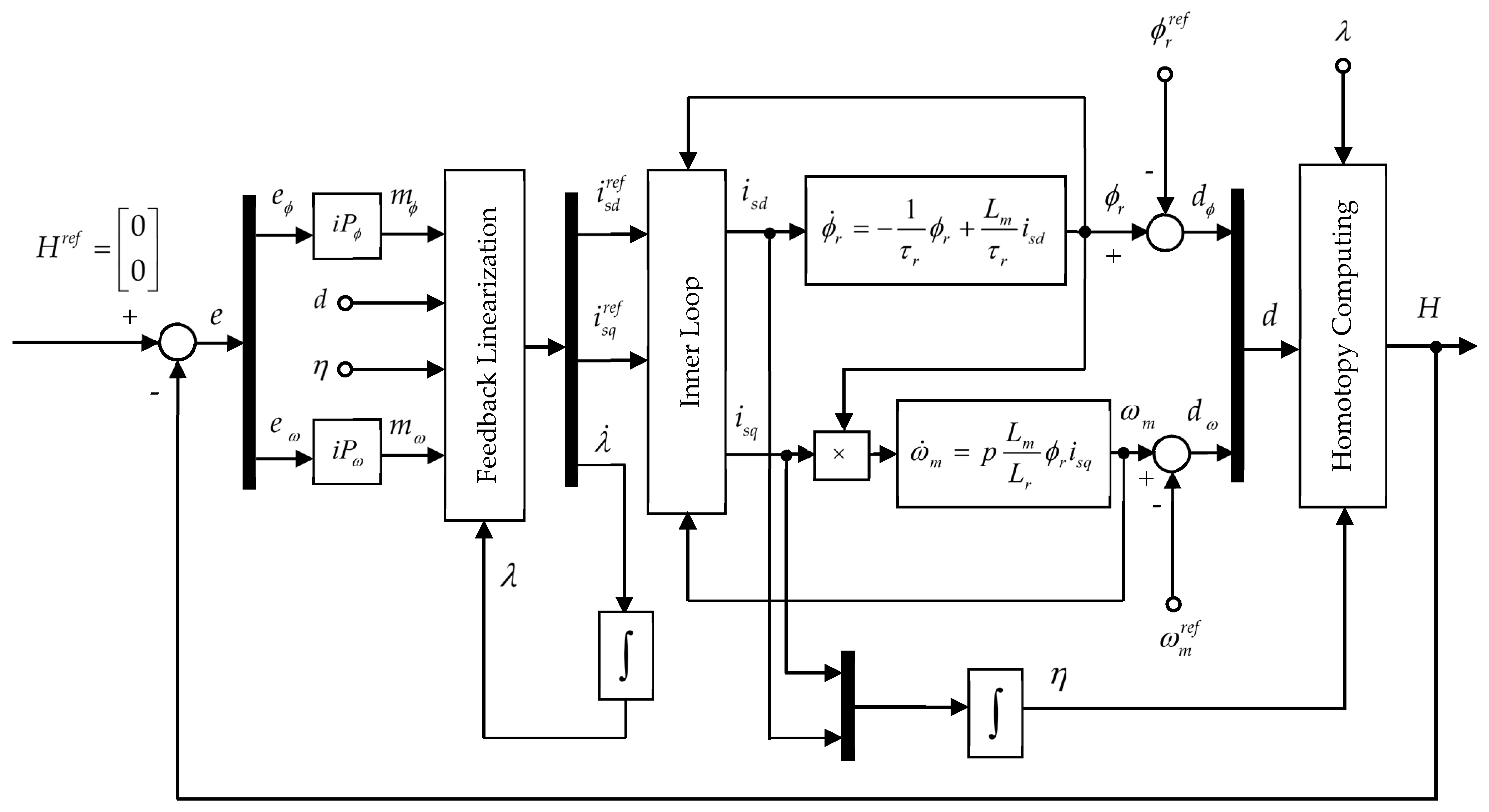
Thus, the outer loop consists of two control loops, one for feedback linearization with Equation (39) and the other for the resulting linear system control. For the second loop, we chose a model-free iP algorithm to control the linear system due to the augmented model parametric uncertainty.

3.2.2. Model-Free iP Controller Design

After the feedback linearization, two integrator-type linear systems were obtained that will be controlled with two model-free iP controllers so that H tracks its zero reference. With the controllers being of model-free type, the models of Equation (41) of the linear systems are not used to tune the parameters but, rather, the discrete time ultra-local model [22,23]:
h ˙ ^ ρ ( k ) = F ρ ( k ) + ψ ρ m ρ ( k ) ,   ρ = ϕ , ω .
where h ˙ ^ ρ ( k ) notes the discrete approximation of the derivative of h ˙ ρ ( t ) , F ρ ( k ) is a time-varying parameter, which depends on the measurement of I/O without information of the plant dynamic model, and ψ ρ is a parameter chosen by the user. Employing I/O measurement, F ρ ( k ) can be estimated with:
F ^ ρ ( k ) = h ˙ ^ ρ ( k ) ψ ρ m ρ ( k 1 ) .
The discrete-time model-free iP control law is defined by [24]:
m ρ ( k ) = 1 ψ ρ ( h ˙ ^ ρ r e f ( k ) F ^ ρ ( k ) + K p ρ ( h ρ r e f ( k ) h ρ ( k ) ) ) ,
where K p ρ is the proportional gain. Substituting F ^ ρ ( k ) from Equation (43) into Equation (44) and considering the control error e ρ ( k ) , the model-free iP algorithm becomes:
m ρ ( k ) = m ρ ( k 1 ) + 1 ψ ρ ( e ˙ ^ ρ ( k ) + K p ρ e ρ ( k ) ) e ρ ( k ) = h ρ r e f ( k ) h ρ ( k ) .
From Equation (46), the term m ρ ( k 1 ) shows that the algorithm has an integral component. The tuning parameters of the iP controllers, ψ ρ and K p ρ , can be designed using different methods as in [25]. In this paper, we proposed a new design approach based on the connection between the iP controllers and the conventional PI.
The outer loop structure with homotopy-based feedback linearization, together with the flux and speed control using model-free iP algorithms, is represented in Figure 3.

4. Case Study

The improvement of the IM vector control by using the proposed cascade control structure with the block diagrams of the inner and outer loops from Figure 2 and Figure 3, implemented using MATLAB/Simulink software version R 2023b, was tested and evaluated by simulation.
The IM specification data were taken from [4,11] and are given in Table 1.
The nominal voltage and current, U N and I N , from Table 1 are related on the root mean square (RMS) values, which, in practice, have a physical meaning. For the vector control, considering the power invariant dq transformation, the nominal values of the space vector magnitude of the voltage and the current are defined as I s N = 3 I N = 16.21   A and U s N = 3 U p N = 400   V .
The performance evaluation was conducted in comparison with the use of the conventional discrete-time PI controllers instead of the MPCC controllers in the inner loop and instead of the model-free iP controllers in the outer loop, respectively. The design of the PI controllers was performed with the pole placement method from [26,27] and it is briefly presented as follows.
The PI controllers from the inner loop described by the transfer function:
C j ( z ) = k p j + k i j T s z 1 ,     j = d , q ,
are designed based on the same plant described by the transfer function obtained from Equation (23):
N j ( z ) = b z a .
Using the two transfer functions in Equations (47) and (48), the following characteristic polynomial of the closed loop control system is obtained:
P c l j ( z ) = z 2 + ( b k p j a 1 ) z + k i j b T s k p j b + a .
Based on the required performances, the percent overshoot σ % , and the settling time t s , the desired characteristic polynomial is constructed:
P c d j ( z ) = z 2 + ξ 1 j z + ξ 2 j ,
whose parameters are computed with:
ξ 1 j = 2 e ζ ω n T s cos ( ω n T s 1 ζ 2 ) ;     ξ 2 j = e 2 ζ ω n T s ,
where the damping ratio ζ and natural frequency ω n are calculated based on the desired performances, and T s is the sampling period. The PI tuning parameters are computed solving the Diophantine equation:
P c l j ( z ) = P c d j k p j = ( ξ 1 j + a + 1 ) / b ;     k i j = ( ξ 2 j + ξ 1 j + 1 ) / b .
In a similar way, the tuning parameters of the PI controllers from the outer loop:
C ρ ( z ) = k p ρ + k i ρ T s z 1 ,     ρ = ϕ , ω ,
are obtained considering that, now, the plant is the integrator N ρ ( z ) = T s / ( z 1 ) obtained after the homotopy-based feedback linearization. In this case, the characteristic polynomial of the closed loop control system is:
P c l ρ ( z ) = z 2 + ( T s k p ρ 2 ) z + k i ρ T s 2 k p ρ T s + 1 .
Using a similar desired characteristic polynomial developed based on performances and solving a Diophantine equation, the following tuning parameters are found:
P c l ρ ( z ) = P c d ρ k p ρ = ( ξ 1 ρ + 2 ) / T s ; k i ρ = ( ξ 2 ρ + ξ 1 ρ + 1 ) / T s 2 .
Employing the IM motor parameters and the desired performances for the inner loop σ % = 4.3 % ,   t s j = 0.0399   s , the following tuning parameters of the inner loop PI controllers are obtained for Ts = 0.4 ms:
k p j = 5.71 ,   k i j = 763.75 .
Similarly, for the outer loop, by imposing the performances σ % = 4.3 % ,   t s ϕ = 0.04   s ,   t s ω = 0.1   s , the tuning parameters of the PI controllers are as follows:
k p ϕ = 179 ,   k i ϕ = 1.5475 10 4 k p ω = 80 ,   k i ω = 3.1502 10 3 .
The MPCCj controllers from the inner loop are implemented using the MPC controller block from the MPC Simulink library [21], which is based on the SISO model in Equation (25). Employing the IM parameters from Table 1, the model becomes:
{ x j ( k + 1 ) = Φ x j ( k ) + γ Δ v s j ( k ) i j ( k ) = [ 1 0 ] x j ( k ) Φ = [ 0.98 0.10 0 1 ] ;   γ = [ 0.10 1 ] .
The constraint formulations for the MPCCd controller are based on the first inequalities from Equations (18) and (23):
0 i s d i s d m a x = i s d N v s d m a x v s d v s d m a x .
and, for the MPCCq controller, the second inequalities:
i s q m a x i s q i s q m a x v s q m a x v s q v s q m a x .
The maximum values of the stator current and voltage of the IM are I s m a x = 1.1 I s N = 17.83   A and U s m a x = V D C / 3 = 433.01   V , where the IM is supplied by a power inverter with the DC-bus voltage V D C = 750   V . Knowing the nominal rotor flux from Table 1, the nominal d-axis current results in i s d N = ϕ r N / L m = 5.43   A , and its maximum value i s d m a x = i d N . Using Equation (14), the parameter γ c = i s d m a x / I s m a x = 0.3 is computed and, finally, with Equation (15), the q-axis current maximum value i s q m a x = 16.98   A results.
In order to obtain the maximum values of the voltages v s d / q m a x from Equations (21) and (22), the parameter γ v = 0.42 is firstly chosen and, then, the maximum values of the voltages u s d / q m a x are calculated using Equation (19), resulting in u s d m a x = 181.86   V and u s q m a x = 392.96   V . Finally, with Equation (22), the maximum values of the voltages v s d / q m a x are determined: v s d m a x = 427.01   V and v s q m a x = 64.08   V .
The operation of the IM is conducted by imposing the nominal value of the rotor flux as its reference, ϕ r r e f = ϕ r N .
For the inner loop, the designed MPCC controllers have the parameters depicted in Table 2.
The outer loop plant in Equation (34), having as outputs the deviations in rotor flux and speed from their references, with the IM parameters from Table 1 becomes:
{ d ˙ = f ( x ) + g ( x ) i s d / q y = d f ( x ) = [ 4.48 ϕ r 0 ] ;   g ( x ) = [ 0.78 0 0 138.07 ϕ r ] .
Since the model in Equation (61) is not feedback linearizable for ϕ r = 0 when the decoupling matrix g(x) is singular, the linear dynamic system in Equation (35) is associated with the outer loop plant model (61). Using the outputs d and η of the two associated systems, a new output H is constructed based on the continuous time-dependent parameter λ [ 0 , 1 ] , utilizing Equation (36). For the augmented system H with the dynamics in Equation (37), the state feedback controller in Equation (40) is designed, having the parameter α = 12.26 , and, thus, a homotopy-based variant of feedback linearization results, which transforms the nonlinear system in Equation (39) into the linear one in Equation (41). The purpose of the state feedback controller (40) is to maintain H = 0 [4] and, for λ = 1 , the deviations defined by Equation (33) will be zero and, thus, the rotor flux and speed track their imposed references. For this reason, H r e f = [ 0 0 ] T is chosen. For the integrator-type linear system in Equation (41) obtained after the homotopy-based feedback linearization, two additional control loops are built with the model-free iP controllers to maintain the reference imposed to H and, respectively, d when λ = 1 . Usually, PI controllers are used for these additional control loops [4,13]. In this paper, the model-free iP controllers capable of dealing with the modeling uncertainty, especially during the variation in the λ parameter from 0 to 1, are proposed. The design of these controllers is made considering the connection between the iP controllers and the conventional PI given in [24] and the following tuning parameters of the iP controller were obtained based on the parameters in Equation (57) of the PI controllers:
ψ ϕ = 1 / ( k P ϕ T s ) = 13.97 ,     K P ϕ = k I ϕ ψ ϕ T s = 86.45 ,   ψ ω = 1 / ( k P ω T s ) = 31.25 ,     K P ω = k I ω ψ ω T s = 39.38 .
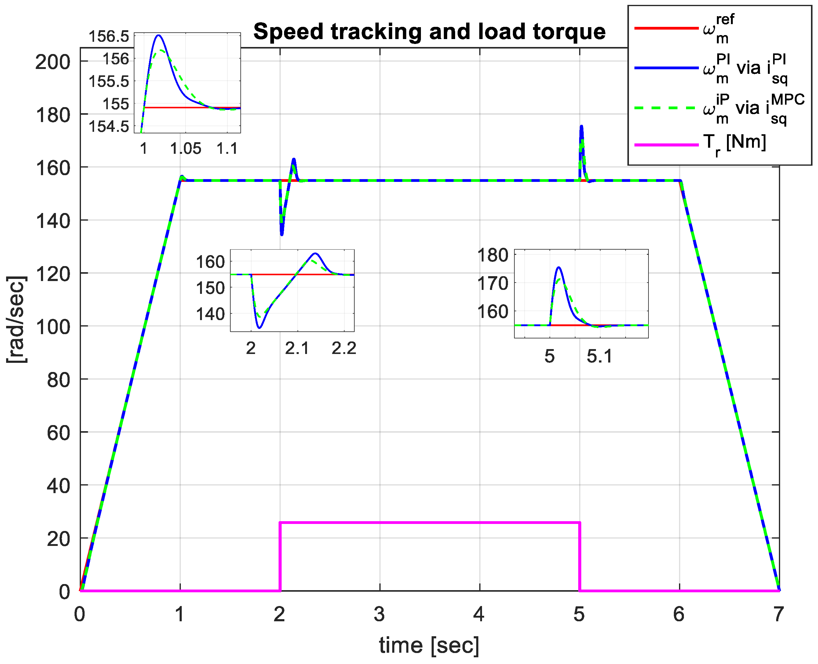
The simulation test consists of an acceleration of the angular speed to 154.9 rad/s within 1 s, keeping this value 5 s, and then deceleration to 0 in 1 s, while the rotor flux is maintained at its nominal value ϕ r N = 0.94   Wb . A high load torque T r = T e N = 25.08   Nm is also applied, starting with t = 2 s for 3 s. The performances obtained with the proposed cascade vector control structure, having MPCC controllers in the inner loop and the homotopy-based feedback linearization of the outer loop plant, followed by the control of the resulting linear system with model-free iP controllers, are compared with those obtained with the conventional PI controllers in the two control loops.
The evolution of the rotor angular speed in relation to its reference during the test is represented in Figure 4 for both the cascade control structures, with advanced control algorithms MPCC and iP and with conventional PI controllers.
Reaching the nominal value of the rotor speed is performed with a slightly lower overshoot of 0.8% in the case of the cascade with the iP and MPCC algorithms compared to the PI controllers’ cascade with an overshoot of 1%. A better rejection of the load torque is also obtained for the case of the advanced algorithms compared to PI.
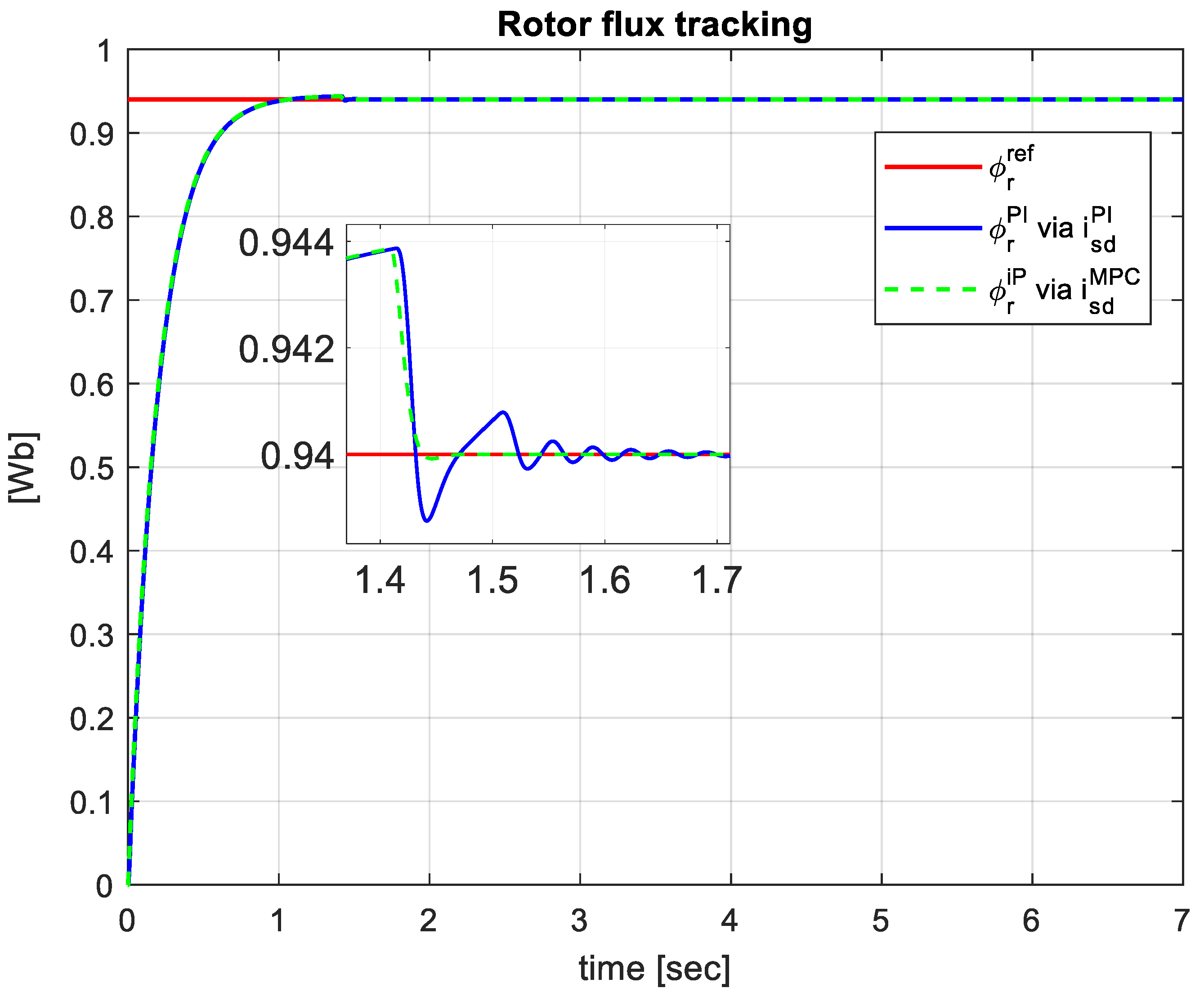
From the responses to the rotor flux reference represented in Figure 5, it can be seen that the performances obtained with the advanced algorithms MPCC and iP are very similar to those of PI controllers, with slightly better behavior of the MPCC–iP tandem. For both cascade control structures, a small overshoot of 0.1% resulted but the return to the steady state is accomplished with damped oscillations when the PI controller is used.
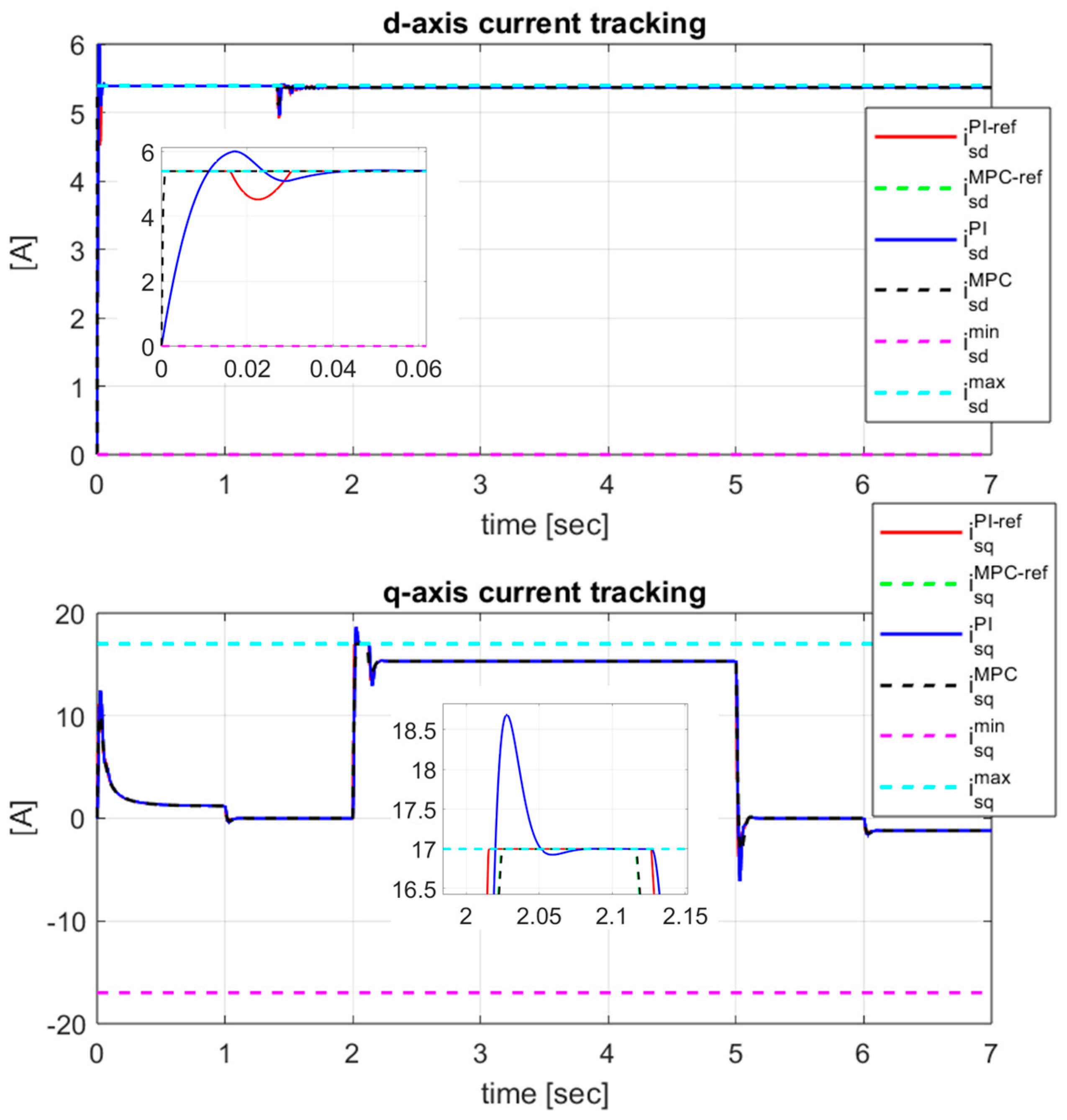
The i s d / q currents tracking their references generated by the feedback linearization block are represented in Figure 6, upper i s d M P C / P I and lower i s q M P C / P I , for the two structures with MPCC controller and, respectively, PI. The limits imposed on the two currents are also represented in the figure. Current limiting is conducted in a different way for the two types of controllers. Thus, for the MPCC controller, by imposing the constraints in Equations (59) and (60) in the design phase, the i s d / q currents do not violate the limits. For the case of the PI controller, the limitation of the currents was conducted by limiting the references generated by the feedback linearization block. But, because, in the transient state, the currents can have overshoot and exceed the reference, the imposed limit is violated. In the upper figure, at the beginning of the transitory state, the i s d P I current obtained with the PI controller exceeds the imposed limit due to an overshoot of 10% and the steady state is reached after a settling time of 0.05 s. The performances obtained with the MPCC controller are superior, the response being without overshoot and the settling time being only 0.001 s. In the lower figure, the current i s q P I exceeds the limit imposed when the high load torque is applied due to an overshoot of 9%. The current obtained with the MPCC controller, being limited by the predictive algorithm, has no overshoot. The settling time is also much lower for MPCC compared to PI.
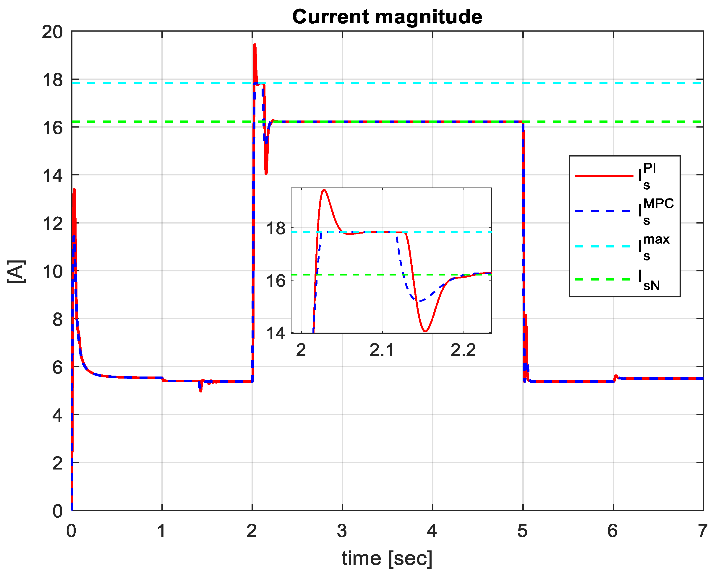
To better illustrate constraint (13) satisfaction regarding the currents, Figure 7 shows the maximum value of the stator current I s m a x and the nominal value IsN together with the maximum values obtained with MPCC and with PI, respectively:
I s M P C = i s d M P C 2 + i s q M P C 2 ,   I s P I = i s d P I 2 + i s q P I 2 .
From the figure, one may notice that, when high load torque is applied at the beginning only I s P I > I s m a x while in the steady state, both stator currents are equal to the nominal current: I s P I = I s M P C = I s N .
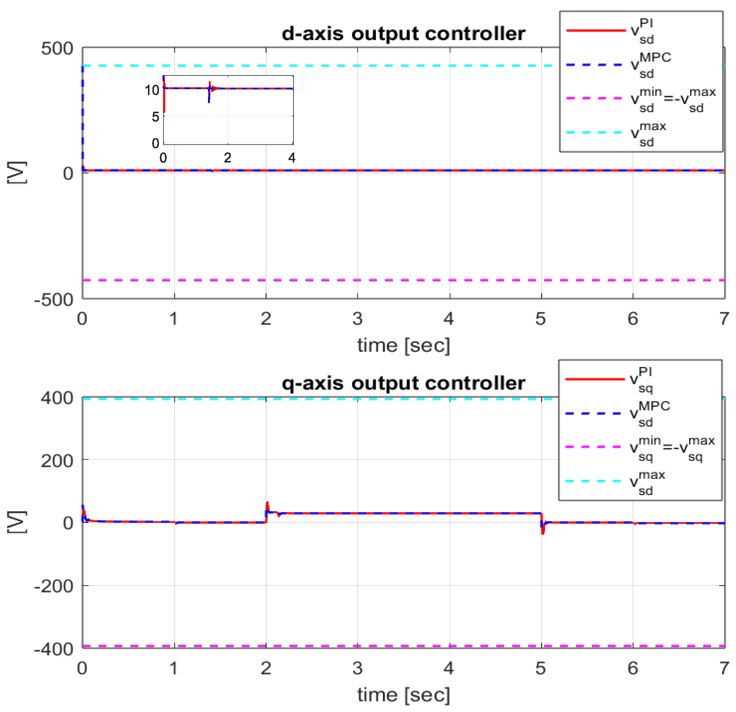
The MPCC and PI current controller outputs, v s d / q M P C and v s d / q P I , together with their limits generated by constraints are depicted in Figure 8, upper v s d M P C / P I and lower v s q M P C / P I . Due to the anticipative action of the MPCC controllers, especially on the d-axis, the dynamics of the current on this axis and implicitly of the flux are a little bit faster as compared to PI.
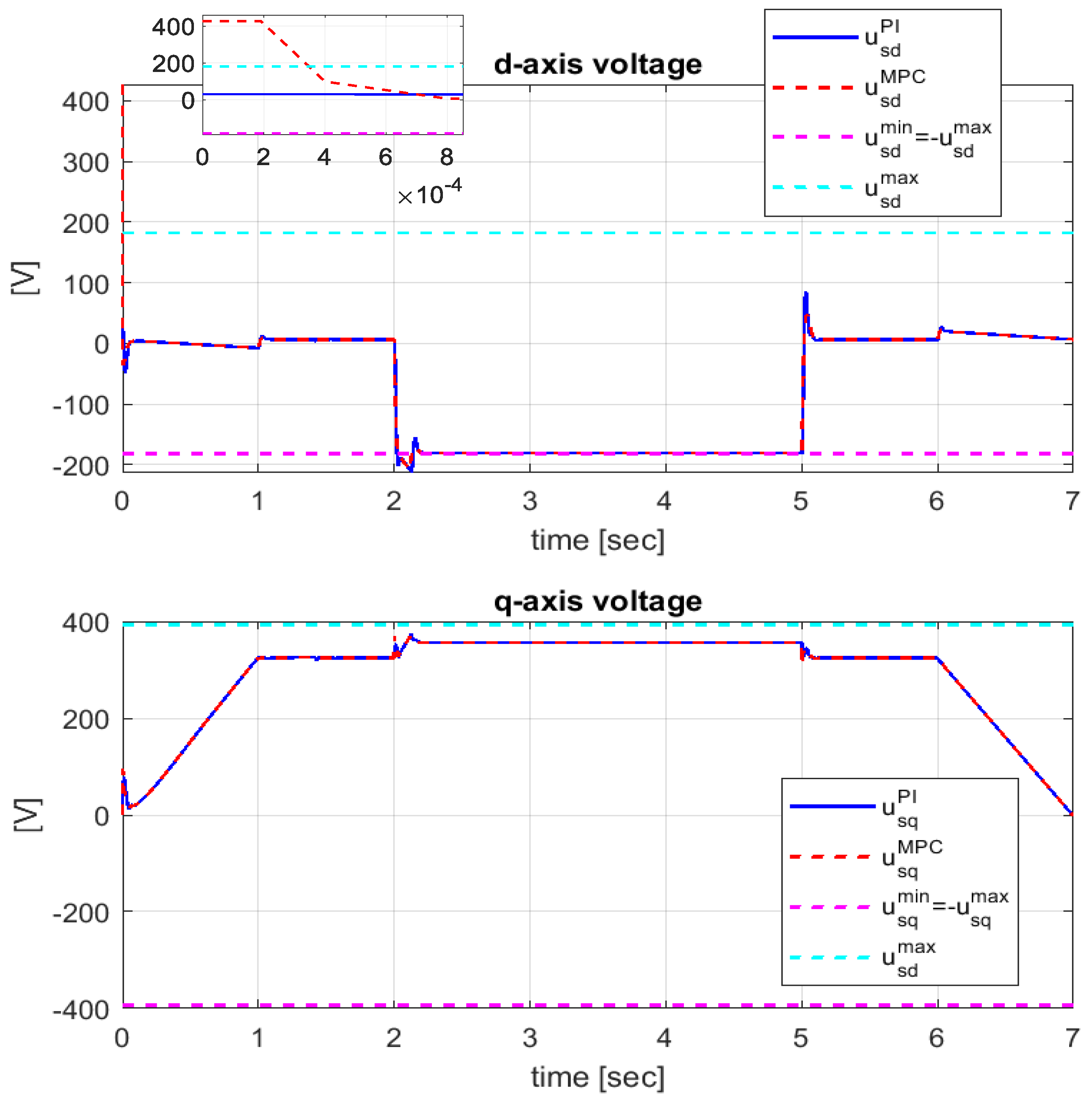
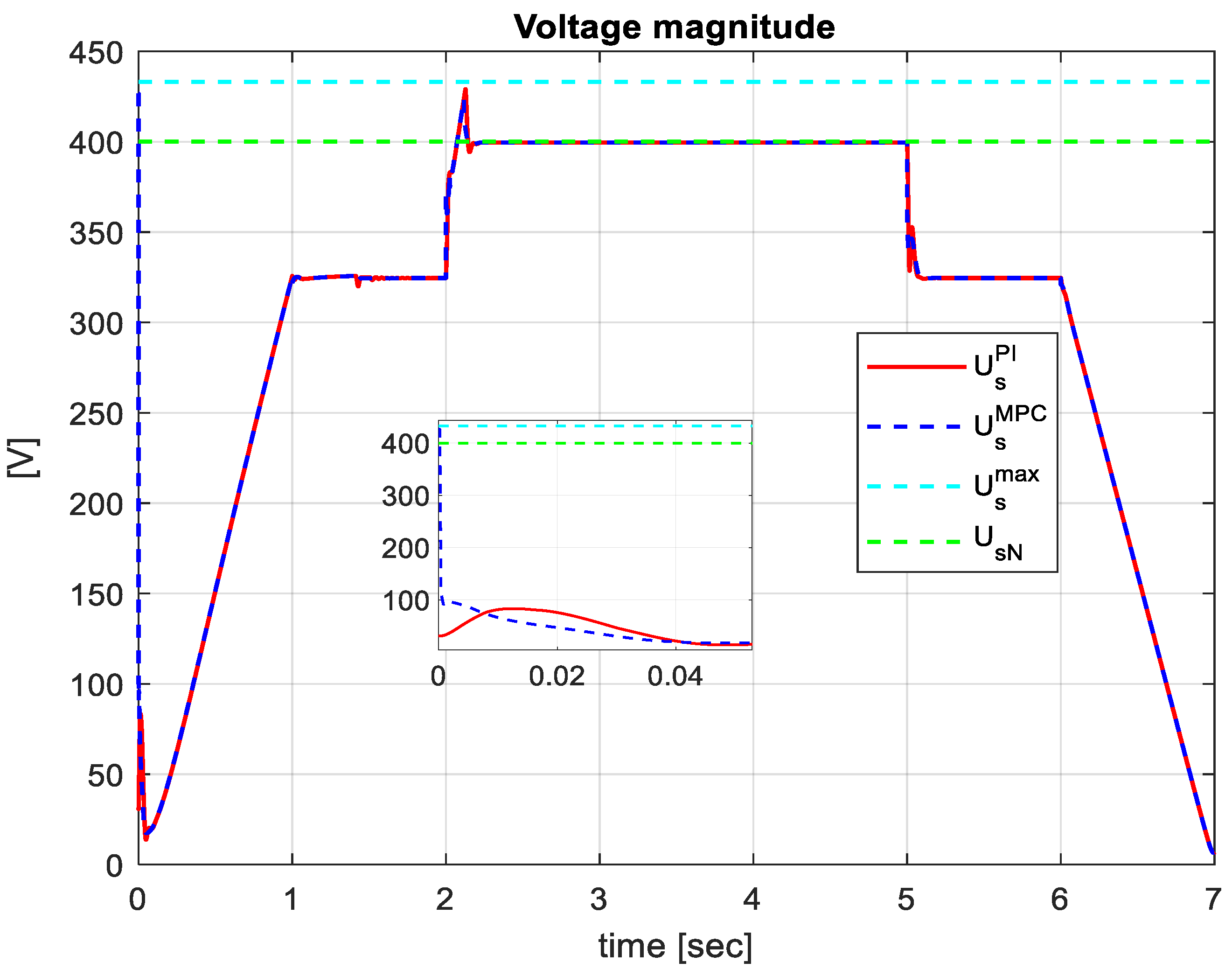
At the same time, due to the MPCC controller constraints and the anti-windup mechanism of the PI controllers, the imposed limits are not violated. For IM safety, it is important to respect the limits imposed on the input voltages u s d / q M P C and u s d / q P I whose dynamics are represented in Figure 9, upper d-axis voltage and lower q-axis voltage. From Equation (9), it follows that the maximum values u s d / q m a x are calculated based on the maximum values of the voltages v s d / q m a x and of the feedforward components u s d / q f f m a x , respectively. As presented in Section 3.1.2, the maximum values of the feedforward components are dependent on the nominal value of the rotor flux ϕ r N and the angular speed ω s N . For the large variations in the flux at the start-up and, respectively, of the angular speed when the high load torque is applied, the flux and angular speed have significantly lower values than the nominal ones and the voltage u s d M P C slightly exceeds the imposed limits for a short period of time. After the flux and the angular speed transitory states, u s d M P C returns within the imposed limits. However, even in the transitory state generated at the start-up or when high load torque is applied, the voltage limit (13) is also fulfilled for the MPCC controller, as is seen in Figure 10, where the stator voltages obtained with MPCC and PI:
U s M P C = u s d M P C 2 + u s q M P C 2 ,   U s P I = u s d P I 2 + u s q P I 2 ,
are represented in relation to the maximum value U s m a x and the nominal one U s N .
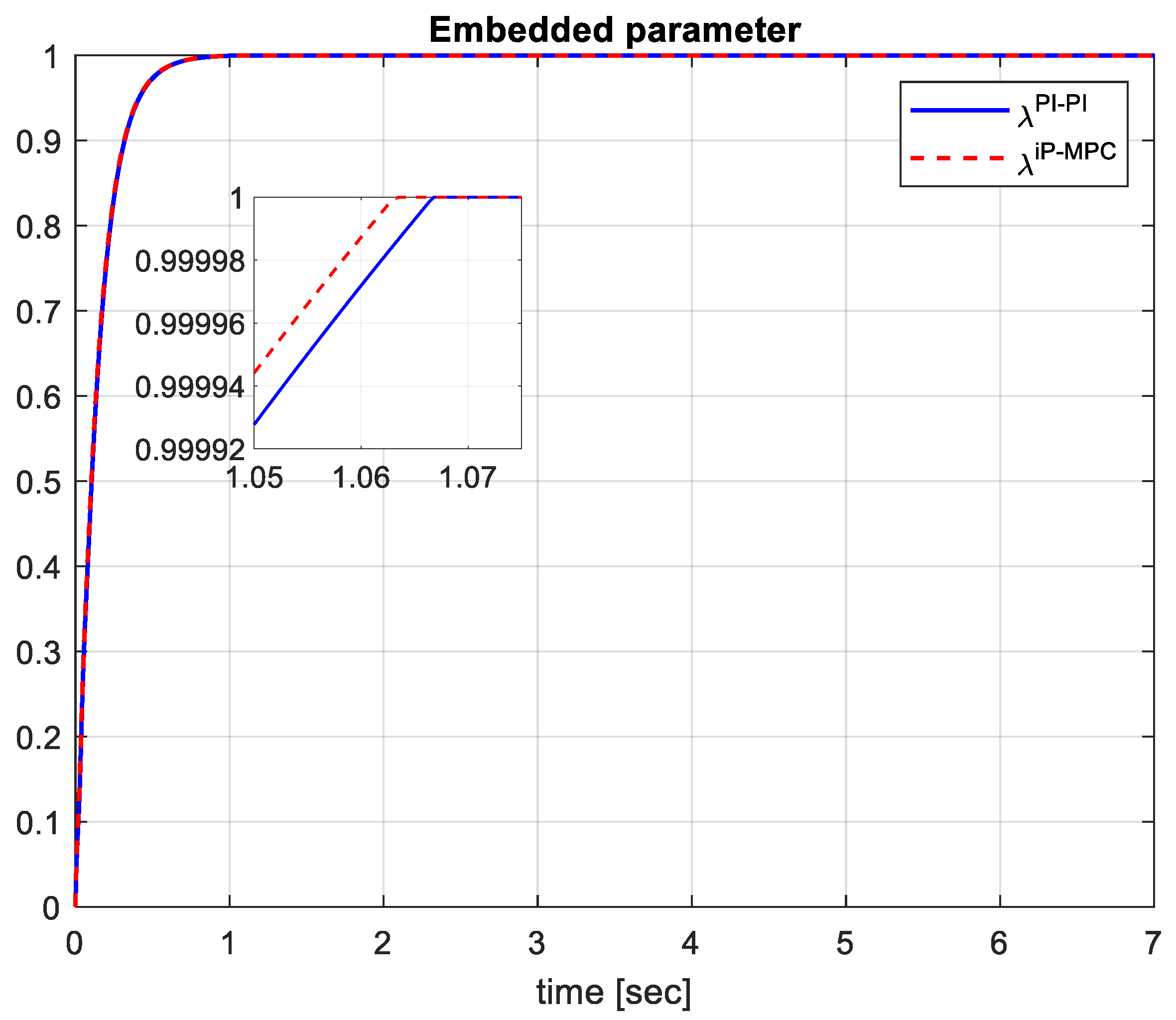
In Figure 11, the smooth transition of the homotopy continuous time-dependent parameter from λ = 0 to λ = 1 is represented, with faster dynamics in the case of the cascade control structure with the advanced MPCC and iP algorithms, compared to the result obtained with conventional PI controllers.
The results obtained in the simulation test shown in Figure 6, Figure 7, Figure 8, Figure 9 and Figure 10 highlight the superior performances of the MPCC algorithm compared to PI from the inner loop through much smaller settling times, without overshoot and satisfying the physics constraints. For the outer loop, Figure 4 and Figure 5 show that, with the model-free iP controllers, better performances were obtained than with PI through lower values of overshoot and settling time, both for the variation in the reference and the load torque.
To globally evaluate the reference tracking performance by the controlled outputs of the two cascade control structures with the advanced MPCC and model-free iP algorithms, respectively, with the conventional PI controllers, and using a homotopy variant of feedback linearization for the decoupling the rotor flux and speed, the following performance indices are used:
J d = 1 N s i m k = 1 N s i m ( i d r e f ( k ) i d ( k ) ) 2 , J q = 1 N s i m k = 1 N s i m ( i q r e f ( k ) i q ( k ) ) 2 , J ϕ = 1 N s i m k = 1 N s i m ( ϕ r r e f ( k ) ϕ r ( k ) ) 2 , J ω = 1 N s i m k = 1 N s i m ( ω m r e f ( k ) ω m ( k ) ) 2 .
In Equation (65), T s t a r t = 0 s is the beginning of the evaluation time, T e n d = 7 s is the simulation time, and N s i m = ( T e n d T s t a r t ) / T s is the total number of samples. The performance indices J d and J q are used to evaluate the current tracking results, while the next two indices, J ϕ and J ω , provide the performance evaluation of the flux and speed responses.
The evaluation results regarding the controlled outputs tracking their references considering the performance indices in Equation (65) are presented in Table 3.
The numerical values of the performance indices from Table 3 show that, with the advanced algorithms in the inner and outer loops, lower values are obtained compared to those obtained with the conventional PI controllers and, thus, the improvement of vectorial control of IM with the proposed control strategy is indicated.
5. Conclusions

To improve the vector control of IM, this paper proposes a cascade control structure that uses the advanced control algorithms in the inner loop and the outer one instead of the classic PI controllers and a homotopy variant of feedback linearization for decoupling the rotor flux and speed. For solving the dq current control problem, a current decoupling algorithm is used in the inner loop, followed by MPCC controllers capable of efficient and independent current control, taking into account the constraints imposed by the electrical signal physics limitations. After decoupling the rotor flux and speed using a homotopy variant of feedback linearization, the resulting integrator-type linear systems are controlled with additional loops with model-free iP controllers to ensure the tracking of the references imposed on the rotor flux and speed. The model-free control algorithms are used due to their capabilities to manage complex dynamics from data, without requiring the knowledge of the plant model, especially during the variation in the homotopy parameter from zero to one. The proposed cascade control strategy with the advanced control algorithms in the two loops has been tested and evaluated by simulation in the Matlab-Simulink environment. The performance evaluation is conducted in comparison with the use of conventional discrete-time PI controllers instead of the MPCC controllers in the inner loop, respectively, and the model-free iP controllers in the outer loop. With the advanced control algorithms, better performances are obtained in comparison with the PI control in terms of tracking the references by the controlled outputs as well as the rejection of the load torque.

Author Contributions

Conceptualization, M.C. and C.L.; methodology, C.L.; software, M.C.; validation C.L.; formal analysis, C.L.; investigation, C.L.; resources, M.C.; writing—original draft preparation, M.C.; writing—review and editing, C.L.; visualization, M.C.; supervision, C.L. All authors have read and agreed to the published version of the manuscript.

Funding

This research received no external funding.

Data Availability Statement

Data are contained within the article.

Conflicts of Interest

The authors declare no conflicts of interest.

References

  1. Leonhard, W. Control of Electrical Drives, 2nd ed.; Springer: Berlin, Germany, 1996. [Google Scholar]
  2. Bose, B.K. Power Electronics and Motor Drives Advances and Trends; Elsevier: Amsterdam, The Netherlands; Academic Press: Cambdridge, MA, USA, 2006. [Google Scholar]
  3. Wang, L.; Chai, S.; Yoo, D.; Gan, L.; Ng, K. PID and Predictive Control of Electrical Drives and Power Converters; John Wiley & Sons, Ltd.: Singapore, 2015. [Google Scholar]
  4. Borisevich, A.; Schullerus, G. Parameter homotopy continuation for feedback linearization of non-regular control-affine nonlinear systems. Int. J. Appl. Math. 2015, 28, 253–273. [Google Scholar] [CrossRef]
  5. Ahmed, A.A.; Koh, B.K.; Lee, Y.I.I. A Comparison of finite control set and continuous control set model predictive control schemes for speed control of induction motors. IEEE Trans Ind. Inform. 2018, 14, 1334–1346. [Google Scholar] [CrossRef]
  6. Garcia, C.; Rodriguez, J.; Silva, C.; Rojas, C.; Zanchetta, P.; Abu-Rub, H. Full predictive cascaded speed and current control of an induction machine. IEEE Trans. Power Electron. 2016, 31, 1059–1067. [Google Scholar] [CrossRef]
  7. Hu, Z.; Hameyer, K. A method of constraint handling for speed-controlled induction machines. IEEE Trans. Ind. Electron. 2016, 63, 4061–4072. [Google Scholar] [CrossRef]
  8. Shiravani, F.; Alkorta, P.; Cortajarena, J.A.; Barambones, O. An improved predictive current control for IM drives. Ain Shams Eng. J. 2023, 14, 102037. [Google Scholar] [CrossRef]
  9. Bašic, M.; Vukadinovic, D.; Grgic, I. Model predictive current control of an induction motor considering iron core losses and saturation. Processes 2023, 11, 2917. [Google Scholar] [CrossRef]
  10. Alkorta, P.; Cortajarena, J.A.; Barambones, O.; Maseda, F.J. Effective generalized predictive control of induction motor. ISA Trans. 2020, 103, 295–305. [Google Scholar] [CrossRef] [PubMed]
  11. Fekih, A.; Chowdhury, N. On Nonlinear Control of Induction Motors: Comparison of Two Approaches. In Proceedings of the 2004 American Control Conference, Boston, MA, USA, 30 June–2 July 2004; pp. 1135–1140. [Google Scholar]
  12. Bodson, M.; Chiasson, J. Differential-geometric methods for control of electric motors. Int. J. Robust Nonlinear Control 1998, 8, 923–954. [Google Scholar] [CrossRef]
  13. Borisevich, A.; Schullerus, G. Switching strategy based on homotopy continuation for non-regular affine systems with application in induction motor control. arXiv 2012, arXiv:1203.5919. [Google Scholar]
  14. Chiasson, J. A new approach to dynamic feedback linearization control of an induction motor. IEEE Trans. Autom. Control 1998, 43, 391–397. [Google Scholar] [CrossRef]
  15. Boukas, T.K.; Habetler, T.G. High performance induction motor speed control using exact feedback linearization with state and state derivative feedback. IEEE Trans. Power Electron. 2004, 19, 1022–1028. [Google Scholar] [CrossRef]
  16. Gastaldini, C.C.; Grundling, H.A. Speed-Sensorless Induction Motor Control with Torque Compensation. In Proceedings of the 2009 13th European Conference on Power Electronics and Applications, Barcelona, Spain, 8–10 September 2009; pp. 1–8. [Google Scholar]
  17. Dendouga, A. Feedback linearization associated to a sliding mode controller for an operating with unity power factor of induction motor fed by matrix converter. SN Appl. Sci. 2020, 2, 879. [Google Scholar] [CrossRef]
  18. Lepka, J.; Stekl, P. 3-Phase AC Induction Motor Vector Control Using a 56F80x, 56F8100 or 56F8300 Device. Design of Motor Control Application. Freescale Semiconductor Application Note. 2005. Available online: https://www.nxp.com.cn/docs/en/application-note/AN1930.pdf (accessed on 28 November 2023).
  19. Bemporad, A. Model Predictive Control Design: New Trends and Tools. In Proceedings of the 45th IEEE Conference on Decision & Control, San Diego, CA, USA, 13–15 December 2006; pp. 6678–6683. [Google Scholar]
  20. Bemporad, A.; Morari, M.; Dua, V.; Pistikopoulos, E. The explicit linear quadratic regulator for constrained systems. Automatica 2002, 38, 3–20. [Google Scholar] [CrossRef]
  21. Bemporad, A.; Morari, M.; Ricker, N.L. Model Predictive Control Toolbox for Matlab–User’s Guide; The Mathworks, Inc.: Natick, MA, USA, 2023; Available online: https://www.mathworks.com/help/pdf_doc/mpc/mpc_ug.pdf (accessed on 28 November 2023).
  22. Fliess, M.; Join, C. Model free control. Int. J. Control 2013, 86, 2228–2252. [Google Scholar] [CrossRef]
  23. Join, C.; Fliess, M.; Chaxel, F. Model-Free Control as a Service in the Industrial Internet of Things: Packet loss and latency issues via preliminary experiments. In Proceedings of the 28th Mediterranean Conference on Control and Automation (MED2020), Saint-Raphaël, France, 16–18 September 2020; pp. 299–306. [Google Scholar]
  24. Baciu, A.; Lazar, C. Iterative feedback tuning of model-free intelligent PID controllers. Actuators 2022, 12, 56. [Google Scholar] [CrossRef]
  25. Baciu, A.; Lazar, C. Model Free Speed Control of Spark Ignition Engines. In Proceedings of the 23rd International Conference on System Theory, Control and Computing (ICSTCC), Sinaia, Romania, 9–11 October 2019; pp. 480–485. [Google Scholar]
  26. Astrom, K.J.; Wittenmark, B. Computer-Controlled Systems: Theory and Design, 3rd ed.; Prentice Hall: Upper Saddle River, NJ, USA, 1997. [Google Scholar]
  27. Wittenmark, B.; Årzén, K.-E.; Åström, K.J. Computer Control: An Overview. IFAC Prof. Brief 2002, 1, 93. [Google Scholar]
Figure 1. The rotor flux space vector aligned with the d-axis.
Energies 17 00875 g001
Figure 2. Inner loop—predictive currents control.
Energies 17 00875 g002
Figure 3. Outer loop—homotopy-based feedback linearization and model-free iP control.
Energies 17 00875 g003
Figure 4. Dynamics of the rotor angular speed.
Energies 17 00875 g004
Figure 5. Dynamics of the rotor flux.
Energies 17 00875 g005
Figure 6. Dynamics of the dq currents.
Energies 17 00875 g006
Figure 7. The MPCC and PI stator currents in relation with the maximum value of stator current.
Energies 17 00875 g007
Figure 8. The outputs of the current inner loop controllers.
Energies 17 00875 g008
Figure 9. The plant inputs of the inner loop.
Energies 17 00875 g009
Figure 10. The MPCC and PI stator voltages in relation with the maximum value of stator voltage.
Energies 17 00875 g010
Figure 11. Homotopy parameter variation.
Energies 17 00875 g011
Table 1. IM specification data.
SymbolDescriptionValue (Unit)
P N Nominal power4000 (W)
ω m N Nominal speed154.9 (rad/s)
U N / U p N Nominal voltage (phase to phase/phase)400/230 (V)
I N Nominal current9.36 (A)
ϕ r N Nominal rotor flux0.94 (Wb)
T e N Nominal electromagnetic torque25.08 (Nm)
R s Stator resistance1.2 (Ω)
R r Rotor resistance0.873 (Ω)
L s Stator self-inductance0.195 (H)
L r Rotor self-inductance0.195 (H)
L m Mutual inductance0.175 (H)
J Rotor inertia0.013 (kg∙m2)
p Number of pole pairs2
Table 2. The MPCC controllers design parameters.
WeightsHorizonsViolation Multipliers
SymbolValueSymbolValueSymbolValue
δ j n / μ j p 2 × 10 5 /0.5 h p 40 W d / q i s d / q m i n / m a x 1 A
ρ j ε 10 5 h c 2 W d / q v s d / q m i n / m a x 0 V
Table 3. The evaluation of the IM control performance.
Control LawPerformance
Inner LoopOuter Loop J d J q J ϕ J ω
PIPI0.03760.13810.01383.5768
MPCCiP0.01030.00090.01292.7723
Disclaimer/Publisher’s Note: The statements, opinions and data contained in all publications are solely those of the individual author(s) and contributor(s) and not of MDPI and/or the editor(s). MDPI and/or the editor(s) disclaim responsibility for any injury to people or property resulting from any ideas, methods, instructions or products referred to in the content.