Abstract
Decarbonizing the current steel and power sectors through the development of the hydrogen direct-reduction iron ore–electric arc furnace route and the 100% hydrogen-fired gas turbine cycle is crucial. The current study focuses on three clusters of research works. The first cluster covers the investigation of the mass and energy balance of the route and the subsequent application of these values in experiments to optimize the reduction yield of iron ore. In the second cluster, the existing gas turbine unit was selected for the complete replacement of natural gas with hydrogen and for finding the most optimal mass and energy balance in the cycle through an Aspen HYSYS model. In addition, the chemical kinetics in the hydrogen combustion process were simulated using Ansys Chemkin Pro to research the emissions. In the last cluster, a comparative economic analysis was conducted to identify the levelized cost of production of the route and the levelized cost of electricity of the cycle. The findings in the economic analysis provided good insight into the details of the capital and operational expenditures of each industrial sector in understanding the impact of each kg of hydrogen consumed in the plants. These findings provide a good basis for future research on reducing the cost of hydrogen-based steel and power sectors. Moreover, the outcomes of this study can also assist ongoing, large-scale hydrogen and ammonia projects in Uzbekistan in terms of designing novel hydrogen-based industries with cost-effective solutions.
Keywords:
energy consumption; economic analysis; electrolyzer; gas turbine; hydrogen; HDRI-EAF; iron ore; optimization 1. Introduction
Iron and steel production emit 7% of the global and 16% of the total industrial emissions of CO2 []. Conventional steel production based on the blast furnace–basic oxygen furnace (BF-BOF) route accounts for 70.8% of global ore-based steel production []. The BF-BOF route mainly uses carbon-intensive coke for reducing iron ore and producing steel; therefore, the route is considered one of the most significant carbon-emitting industries, with more than 1.8 tons of CO2 emitted per ton of liquid steel production [,]. Along the BF-BOF route, the direct reduction of iron ore is also emerging, and several approaches on this route have been developed, such as the direct reduction of iron ore with carbon monoxide by using natural gas or a carbon-based reducing agent []. Considering the significant amount of CO2 emissions from the conventional steel sector, the hydrogen direct-reduction iron ore–electric arc furnace (HDRI-EAF) has showcased a positive impact on the steel industry. This is attributed to its use of hydrogen as a reducing agent, replacing carbon-intensive fossil fuels and reducing CO2 emissions by 95–100% [,]. This process offers an opportunity to incorporate renewable energy into the production of green hydrogen, aligning with the demand for sustainable products in the market [].
There are four types of direct reduction processing: shafts, rotary kilns, fluidized beds, and retorts. In April 2021, Primetals Technologies demonstrated a hydrogen-based fine-ore reduction (HYFOR) pilot plant at the Voestalpine Donavitz steelworks in Austria [,]. The pilot plant can reduce fine iron ore with a particle size of less than 0.15 mm. The plant consists of a preheating and oxidation unit, a gas processing plant, and a reduction unit to produce iron. It was also mentioned that the pilot plant is a modular type that can be accommodated on iron ore mining sites, reducing the transportation costs of raw materials (e.g., hematite or magnetite) []. In addition to the reports from Primetals Technologies, Mitsubishi Heavy Industries (MHI) also published their technical report in June 2022 about the same project, titled “the HYFOR process” []. The report provided more details on the project, including schematics of the pilot plant and the prospective industrial prototype, which were mentioned and explained. Additionally, four unresolved points were highlighted: the required residence time for achieving the desired metallization degree, the gas consumption and utilization features in connection with the superficial gas velocity and pressure in the reactor, the optimum temperature of the inletting gas for avoiding the sticking of particles in the distributing section of the reducing gas in the reactor, and understanding the reducibility of magnetite in case of a lack of hematite resources. The report also outlined the possibility of building a commercial plant with a capacity of 5–15 tons per hour based on continuous production [].
In terms of the kinetics of iron ore reduction, several factors affect the process, including, but not limited to, temperature, pressure, gas composition, grain size, porosity, mineralogy, and gangue [,,]. Heidari et al. [,,] discussed several factors influencing the reduction of iron oxides, such as high temperatures accelerating the reduction process and the possibility of reducing iron ore at low temperatures. In the case of using hydrogen as a reducing agent, a higher temperature positively contributes to the thermodynamics and kinetics of the reduction process []. When using carbon monoxide as a reducing agent, a higher temperature decreases the yield of the reduction [,]. Therefore, it is important to understand the behavior of each reducing agent in the reduction process of iron ore. In most of the previously published papers, a temperature range between 500 °C and 1100 °C was mentioned as an experimental condition for reducing iron oxide. The full reduction of iron oxide is still possible at different temperature profiles within the above-mentioned range, with varying experimental parameters, including the residence time and the mass of the reducing agent []. Regarding the fastest reduction process of iron ore, a reaction at 900 °C resulted in a full reduction in 250 s (4 min and 10 s) [,]. Zakeri et al. [] also revealed an 80% reduction of Fe2O3 with CaCO3 and the achievability of a fast reduction with larger amounts of calcium carbonate (i.e., from 1% to 10% of the ore weight). Zakeri et al. also broadly explained the effects of different impurities in iron ore when reduced with hydrogen and CO-reducing agents [].
Many studies have conducted experiments using not only hematite (Fe2O3) but also magnetite (Fe3O4) and wüstite (FeO) to produce iron and steel []. This is due to the availability of each iron oxide in different countries. The reduction of hematite to iron consists of three phase-changing steps, namely Fe2O3 → Fe3O4 → FeO → Fe. The formation of FeO takes place at temperatures above 570 °C, which is slow in terms of the reduction kinetics []. Regarding magnetite reduction with hydrogen, Zheng et al. [] investigated and analyzed the parameters affecting the reduction process, such as the oxidation temperature (i.e., 800 °C), oxidant content (i.e., 1.5 wt.% of MgO powder), and reducing gas velocity (i.e., 0.45 m/s).
As one part of the current study highlights the hydrogen-based reduction of iron ore, it is important to evaluate and understand the potential of hydrogen production for the process, which varies from country to country. The stoichiometric consumption of hydrogen in the reduction process is 54 kg per ton of liquid steel production. The currently available and large-scale production of hydrogen is based on steam methane reforming (SMR). The SMR process requires fossil fuels to produce hydrogen fuel, which is currently not welcomed by many countries in the world. Many new projects in this direction prioritize using an electrolyzer for producing green hydrogen [].
Moreover, Sohn et al. also tested the reduction rate of iron ore under the moving-bed principle, where the reducibility of iron was observed within a temperature range of 500–1000 °C []. Initial evaluations of the HYBRIT project declared the feasibility of the HDRI-EAF route, particularly in Sweden and Finland []. In terms of the decarbonization of EAF, a review by Echterhof [] mentioned incorporating biomass or other alternative sources instead of fossil fuel-based carbon into the steel-making process. As for the cost analysis of steel produced by the HDRI-EAF route using hydrogen fuel as a reducing agent, it was reported that the capital expenditure (CAPEX) of the route ranged from 111.9 to 118.7 USD/ton of steel production []. Regarding the levelized cost of production (LCOP) of the HDRI-EAF route, Vogl et al. [] reported a range of 361–640 EUR/ton of steel production, while Bhaskar et al. [] found the LCOP at 669 USD/tls and another range (622 USD/tls and 722 USD/tls) was also found by Bhaskar et al. [] under different electricity purchase schemes for HDRI-EAF route consumption.
On the other hand, the power sector emitted 14.6 gigatons of CO2 in 2022, the highest value compared to other economic sectors []. One method of reducing CO2 emissions in the power sector is to replace fossil fuels with hydrogen, biofuels, ammonia, and other alternative fuels [,,,]. Simultaneously, incorporating hydrogen into a gas turbine will contribute to bolstering electrical grid stability amidst the growing integration of renewable energy and the shift towards sustainable, carbon-neutral power generation [,,]. The combustion of hydrogen in a gas turbine has been studied for many decades. In 1937, Dr. Hans von Ohain conducted research on the combustion of hydrogen fuel in a gas turbine and identified the main obstacle in this process as the burnout of the metal in the hot parts of a gas turbine unit [].
In this study, hydrogen-assisted process optimization and production cost comparison analyses were investigated between two sectors, namely the steel and power sectors, based on energy and mass balance calculations.
Firstly, a process flow diagram was designed, and the mass and energy balance of the process were determined for each unit.
Secondly, an experimental apparatus was designed under laboratory conditions, and experimental conditions were set up, with consideration to the mass and energy balance. A series of experiments were conducted, and optimal conditions were determined by elaborating on the experimental strategy.
Thirdly, technical and economic evaluations of a hydrogen-fired gas turbine were performed using the Aspen HYSYS v 8.8 tool. Additionally, a combustion kinetics model of a 100% hydrogen-fired gas turbine model was developed using the Ansys Chemkin Pro 2019 R1 tool.
Finally, comparative analyses were conducted, taking into consideration the levelized cost of production of each product (i.e., steel and electricity).
2. Materials and Methods
2.1. Structure of HDRI Experiments
Figure 1 depicts the process flow diagram of the experimental apparatus, building upon the previous research conducted by Alikulov and Xuan []. Experimental conditions were established based on the mass balance of the process, with a ratio of 54 kg of H2 for reducing 1428.00 kg of Fe2O3. The corresponding value of 0.037 g or 0.42 L of H2 was determined for reducing 1 g of Fe2O3. Since the mass flow controller metric was in the standard liter per minute (SLM), the value of 0.42 L of H2 for reducing 1 g of Fe2O3 was multiplied by the residence time of each experiment. If the designed flow rate control range of the mass flow meter was between 5–100% of the nominal value of 20 SLM, then a controlling value of at least 1 SLM must be set up. Ultimately, 1 L of H2 was set up to reduce 2.36 g of Fe2O3. For any residence time value, the amount of feedstock remained the same, and the final decision on optimization was based on multiplying the hydrogen flow rate by the designated residence time. Initially, in this research work, residence times of 5, 10, and 15 min were selected for temperatures ranging from 750 to 800 °C. After conducting a series of experiments, it was decided to focus on a temperature of 770 °C by conducting more detailed, timely experiments within the range of 1 to 7 min. The pressure for the experiments was set at 0.001 MPa. Regarding the structure of the experimental apparatus, Figure 1 depicts details that include a ceramic tube electric furnace (1), temperature controller (2), sealing assembling tools (3), mass flow controller (4), hydrogen cylinder (5), nitrogen cylinder (6), CB boat (7), water container (8), and mechanical valve (9) for controlling the mass flow of nitrogen.
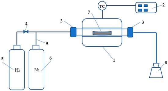
Figure 1.
Process flow diagram of the experimental apparatus [].
2.2. Specification of Route Units
In the HDRI-EAF process, hydrogen serves as a reducing agent to produce sponge iron, and the reaction is endothermic, demanding energy for its operation. In this study, a process flow diagram was constructed, drawing from previous research []. The diagram comprises various units, such as an electrolyzer, a heat exchanger for preheating hydrogen, an iron ore reducer, a preheater for iron ore, and an electric arc furnace. Additionally, specific materials are necessary to run the process, including water, electricity, iron ore, and char.
Initially, the energy and mass balances of the process were calculated based on the stoichiometric reactions, namely Equation (1) [] and Equation (2).
where Fe2O3, H2, Fe, H2O, and O2 represent iron ore, hydrogen, sponge iron, water, and oxygen, respectively.
First, H2O is split into H2 and O2 using an electrolyzer. Subsequently, the produced hydrogen is employed in the iron ore reduction process, aiming for the production of 1 ton (1000.00 kg) of steel with a composition of 0.999Fe:0.001C.
Several assumptions are made as follows:
- -
- Incompressible fluid.
- -
- Ideal gas/low-pressure gases.
- -
- No moving parts, horizontal units, or kinetic energy changes are neglected.
- -
- Steady flow heat transfer.
- -
- Processes under constant pressure.
2.2.1. Balance on the Reactive Process (Electrolyzer)
Figure 2 depicts the process flow diagram of the electrolyzer.
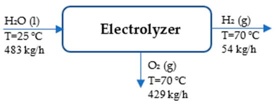
Figure 2.
Process flow diagram of electrolyzer.
According to the references, H2 (g) and O2 (g) are assumed to be at 25 °C and 1 atm []. Table 1 presents the streams of mass and energy in the electrolyzer unit.

Table 1.
Inlet and outlet enthalpies and mass and energy balance in electrolyzer.
The specific enthalpies of each material are as follows:
H2O (l, 25 °C):
H2 (g, 70 °C):
O2 (g, 70 °C):
The energy balance of the electrolyzer based on the first law of thermodynamics is as follows [,]:
The energy required for the electrolyzer is found from the following equation [,]:
2.2.2. Balance on the Non-Reactive Process of HDRI-EAF (Hydrogen Preheater)
Figure 3 depicts the hydrogen preheater to help understand the process within the preheater.

Figure 3.
Process flow diagram of hydrogen preheater.
The energy values of the hydrogen preheater are found from the following Equations [,]:
Then, the enthalpies of each point are calculated.
H2 (g, 70 °C):
H2 (g, 500 °C):
If Q equals ∆H from Equation (4), as assumed earlier, then the energy required for the hydrogen preheater is found from the following equation:
2.2.3. Balance on the Non-Reactive Process of HDRI-EAF (Iron Ore Preheater)
The energy values of the iron ore (hematite) preheater are found from the following equations []:
Figure 4 depicts the process in the iron ore preheater.

Figure 4.
Process flow diagram of iron ore preheater.
Fe2O3 (s, 800 °C):
The reference data are as follows:
If Q = in Equation (4), as assumed earlier, then the energy required for the iron ore preheater is found from the following equation:
2.2.4. Balance on the Reactive Process (Reducer Unit)
Figure 5 illustrates the reducer unit to aid in understanding the ongoing process.
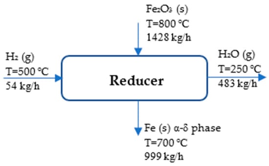
Figure 5.
Process flow diagram of reducer.
The references state that H2 (g), O2 (g), and Fe (s) are at 25 °C and 1 atm []. Table 2 displays the stream of energy and mass in the reducer.

Table 2.
Inlet and outlet enthalpies and mass and energy balance in reducer.
The specific enthalpies of each material are as follows []:
H2 (g, 500 °C):
Fe2O3 (s, 800 °C):
Fe (s, 700 °C) is found by using the Shomate equation:
The conditions are as follows: T = temperature (K)/1000, coefficients within the range of 298–700 K (α-δ phase): (a = 18.42868, b = 24.64301, c = −8.913720, d = 9.664706, and e = −0.012643) and within the range of 700 K–1042 K (α–δ phase): (a = −57,767.65, b = 137,919.7, c = −122,773.2, d = 38,682.42, and e = 3993.080) [].
H2O (g, 250 °C):
If Q = from Equation (4), as assumed earlier, then the energy required for reducing the iron ore was determined by the following equation:
2.2.5. Balance on Reactive Process (Electric Arc Furnace)
Figure 6 depicts the process flow diagram of the EAF, indicating the input and output materials.
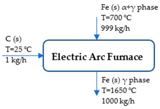
Figure 6.
Process flow diagram of EAF.
The references state that C (s) and Fe (s) are at 25 °C and 1 atm []. Table 3 presents the energy and mass stream in the EAF tool of the route.

Table 3.
Inlet and outlet enthalpies and mass and energy balance in the EAF.
Fe (s, 700 °C, α-δ phase):
C (s, 25 °C):
Fe (s, 1650 °C):
The assumption is as follows: HFe, 1923.15 K is not different from HFe, 1809 K because of the limitation of experimental data. T=temperature (K)/1000, coefficients within the range of 298 K–1809 K (γ phase): (a = 23.97449, b = 8.36775, c = 0.000277, d = −0.000086, and e = −0.000005) [].
If Q = from Equation (4), as assumed earlier, then the energy required for the conversion of sponge iron to steel is determined by the following equation []:
After calculating the mass and energy balance of the HDRI-EAF process, experiments were conducted to understand the behavior of iron ore reduction and optimize the reduction process using the following equation [,]:
where R represents the yield of reduction, is the total weight loss during hydrogen reduction, and is the total weight of O2 present in Fe2O3. Iron ore is assumed to be pure hematite without any other compositions. The composition of Fe2O3 is 69.9% Fe and 30.1% O2.
The levelized cost of production (LCOP) of steel was determined by the following equation [,]:
where Ccapex represents the total investment cost, encompassing the cost of all the main and auxiliary units in the route, and ACC is an annuity factor. Copex, Cmaint, Clabor, and Cemission are the costs associated with the operation, maintenance, labor, and emissions within the route, respectively. The annuity factor of the route is determined by the following equation [,]:
where r is the discount rate, and n is plant life. In this study, the life span of the HDRI-EAF route-based plant is 20 years, with a discount rate of 10%.
Additionally, the net present value (NPV) of the plant is crucial for the accurate calculation of the LCOP over the selected life span period, and it was determined by the following equation []:
where CF, r, and n represent the cumulative cash flow, discount rate, and the life span of the plant, respectively.
2.3. 100% Hydrogen-Fired Gas Turbine Modeling and Specification
The gas turbine unit of the existing combined heat and power (CHP) plant [] with a 7.6 kW capacity has been selected for developing a 100% hydrogen-fired gas turbine model. Based on the technical specifications of the existing plant, a new model has been designed to evaluate the performance of the cycle. Aspen HYSYS v 8.8 software, utilizing the Peng–Robinson fluid package, was employed to evaluate the technical parameters of the designed model, including the enthalpy and entropy of fluid and fluid mixtures in the cycle. Figure 7 depicts the process flow diagram of the 100% hydrogen-fired gas turbine unit. Technical specifications of the cycle, based on 100% hydrogen combustion, are provided in Table 4. Considering the given technical specification, the specific fuel consumption in the designed model accounted for 1.24 kg/kWh compared to 0.31 kg/kWh in the reference case (i.e., 100% natural gas-fired CHP plant).

Figure 7.
Process flow diagram of 100% hydrogen-fired combined heat and power plant.

Table 4.
Technical specifications of the air compressor and gas turbine for the 100% hydrogen-fired CHP plant.
In the model, the following reaction equation for the combustion of hydrogen was used []:
In the analysis of the combustion process analyses in the design model, another model was developed using Ansys Chemkin Pro 2019 R1 software to evaluate the NOx emissions when the cycle was fully operated on hydrogen fuel. Since there were no CO2 emissions from the 100% hydrogen-fired CHP plant, the anticipation of NOx emissions became a critical consideration, aligning with regulatory requirements for the power sector. Figure 8 illustrates the process flow diagram of the gas turbine network developed using Ansys Chemkin Pro 2019 R1 software. To mitigate the NOx emissions, the model employed the staging of an inlet air method. Additionally, an exhaust gas recycling method was applied to reduce the amount of unburned gas in the exhaust.
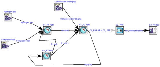
Figure 8.
Process flow diagram of a gas turbine with multi-fuel combustion approaches.
Figure 9 illustrates the method for investigating combustion kinetics in the gas turbine network. The network comprises three zones: the mixing zone, flame, and post-flame zones. In the mixing zone, air and hydrogen are premixed before being sent to the flame zone. In the flame zone, a portion of the air is allocated to reduce thermal NOx formation, and part of the exhaust gases are recycled to ensure the complete combustion of the working fuel in the network. The developed model was simulated by applying the GRImech 3.0 mechanism, which included 5 elements (C, H, O, N, and Ar), 53 chemical species, and 325 reactions for analyzing the chemical kinetics of the network []. Figure 8 includes several units, namely the perfectly stirred reactors (PSR), divided into three parts. PSR R1 represents the mixing, PSR R2 represents the recirculation zone, and PSR R3 represents the flame zone of the gas network based on the illustration given in Figure 9.
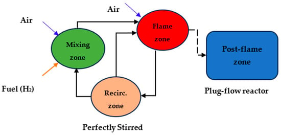
Figure 9.
Process flow diagram of gas turbine network describing three target zones: mixing, flame, and post-flame zones.
The thermal efficiency of the gas turbine network was determined using the following equation:
where is the pressure ratio of the cycle, which ranges between 11 and 16, and γ is the adiabatic constant []. The total power output from the cycle was calculated from the following equation:
where Wturbine is the power generated by the gas turbine’s generator, and Wcompressor is the power consumed by the air compression unit.
In turn, the power consumed by the air compressor, Wcompressor, was found from the following equation:
In the case of the power generated by the gas turbine generator, Wturbine, it was found from the following equation:
The isentropic (ideal) efficiency of the compressor (ƞc) was determined from the following equation:
where Ɛpc is the pressure ratio of a compressor, and γ and ƞc/p are the ratio of specific heats and the polytropic efficiency of the compressor, respectively.
Since “adiabatic” and “isentropic” efficiencies are used interchangeably, isentropic power is considered an ideal power.
The polytropic efficiency of the compressor (ƞc/p) was determined by the following equation:
The isentropic efficiency of the gas turbine (ƞt) was determined by the following equation:
The polytropic efficiency of the gas turbine (ƞt/p) was determined by the following equation:
where n and γ are the polytropic index and the ratio of specific heat, respectively.
An expression relating the isentropic and polytropic efficiencies of the gas turbine, with emphasis on the pressure ratio, was calculated from the following equation:
where Ɛpt and γ are the ratios of pressure and specific heat of a gas turbine, and ƞt/p is the gas turbine’s polytropic efficiency [,].
Since an evaluation of the CO2 emissions from the cycle is one of the main parameters of decarbonization studies, the CO2 emissions of the model have been determined from the following equation:
where Q (energy/time) represents the input energy in the system, and EF (kg CO2/energy) is the emission factor of the fuel used in the system [].
Regarding the economic features of the model, the levelized cost of electricity (LCOE) is a criterion, and the following equation provides detailed information []:
where It is the capital expenditure, including the cost of investment and construction works over t years, Mt is the operational expenditure, including the cost of operation and maintenance over t years, Ft is the operational expenditure, including expenses on using fuel over t years, Et is the total power output over t years, and r and n are the rate of discount and the lifespan of the technology, respectively.
3. Results and Discussions
In this section, the results and discussions are compiled using two approaches, where hydrogen fuel was used as a reducing agent in the steel industry and as a working agent for combustion purposes in the power sector. First, the mass and energy balance and optimized reduction process results are presented. It is assumed that the reducer is in a static and horizontal state. Energy consumption and the speed of reduction are compared with previous studies and discussed to demonstrate the novel approach. Afterward, the LCOP for 1 ton of liquid is still found for further comparison with 1 kWh of electricity generated from a gas turbine unit that fully runs on hydrogen fuel, aiming to understand the future perspectives of each sector. This section also includes the development of a 100% hydrogen-fired gas turbine unit with optimized operational conditions. It is assumed that the gas turbine has stable operation under the 100% hydrogen combustion mode. This assumption was made based on a previous study that successfully achieved the operation of a gas turbine with 100% hydrogen combustion [,].
3.1. Process Flow of HDRI-EAF Route
The mass and energy balance of the HDRI-EAF, composing electrolyzer, hydrogen and iron ore preheaters, iron ore reducer, and an electric arc furnace, are depicted in Figure 7. All values are calculated based on the target amount of the product, namely 1 ton of liquid steel production. In the mass and energy balance, it is assumed that there are no hydrogen losses, and the required amount of hydrogen for running the process is calculated from stoichiometric values. Additionally, the mass of slag, CO, and CO2 are neglected in the calculation, as the main objective of the study was to find stoichiometric values and conduct experiments to determine the most optimal reduction mode of the process. The reason for using an electrolyzer in the process is to design the process flow diagram based on green renewable energy and to avoid fossil fuel-based hydrogen production approaches. Sources of electricity for running the electrolyzer are not specified, though previous studies emphasize the use of wind, solar, and other renewable energy sources for the decarbonization of the HDRI-EAF route [,,,,,,]. The mass of necessary materials, that is, 1428.00 kg of Fe2O3, 1 kg of carbon (C), 54 kg of H2, and 483 kg of H2O to produce 1 ton of liquid steel, is also depicted in Figure 10.
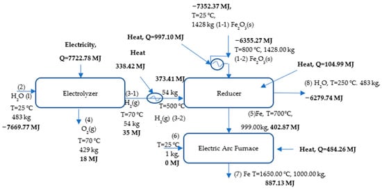
Figure 10.
Process flow diagram of hydrogen direct iron reduction.
3.2. Energy Consumption of HDRI-EAF Route
Since the HDRI-EAF mainly consumes electricity in running the whole process, the analysis of energy consumption is very important for process feasibility and commercialization. The results of the current study state that the electrolyzer needs 7722.78 MJ (2145.21 kWh), the hydrogen preheater needs 338.42 MJ (94 kWh), the iron ore preheater needs 997.105 MJ (276.97 kWh), the reducer needs 104.99 MJ (29 kWh), and the EAF needs 484.26 MJ (134.51 kWh) of energy to produce 1 ton of liquid steel within the HDRI-EAF process. The calculations did not include the energy requirement of hydrogen storage in the process. In total, the energy requirement of the HDRI-EAF based on the findings is 9647.55 MJ/tls or 2679.69 kWh/tls. Table 5 summarizes the flow of energy and mass in the HDRI-EAF process based on the results of the current study.

Table 5.
Summary of energy and mass balance of the process.
A previous study already reported the total specific energy consumption (SEC) requirement for the HDRI-EAF route without a hydrogen storage system, amounting to 3.72 MWh/tls, which exceeds the 1.01 MWh SEC found in this research []. Moreover, the SEC of the conventional steel manufacturing industry, based on the BF-BOF route, consumed 3.48 MWh/tls []. Another study’s report mentioned the SEC of the HDRI-EAF route totaling 3.48 MWh/tls, while the SEC of the BF-BOF route was 3.68 MWh/tls []. In addition, the minimum value of the total SEC in the direct reduction of the iron process, accounting for 12.2 GJ/tls or 3.388 MWh/tls, was reported, but a higher amount of the total SEC in the blast furnace, totaling 15.7 GJ/tls or 4.361 MWh/tls, was reported by the research []. From the SEC of the current research findings, as mentioned in Figure 11, the highest energy demand was found in the electrolyzer, which consumed 80% of the energy of the SEC. The next highest energy consumption amounts were found in the hydrogen preheater, with 1.74 kWh SEC per kg of H2, in the iron ore preheater, with 0.19 kWh SEC per kg of Fe2O3, and in the EAF, with 0.13 kWh SEC per kg of sponge iron processing. Based on the above-mentioned SEC in each unit, it is advisable to build a strategy for reducing the energy consumption in the HDRI-EAF route directed towards decarbonization and the commercialization of the process. Li et al. [] mentioned in their studies that the heat energy of the effluent from the shaft furnace composing H2 and H2O, can be used in the heat exchanger of H2 and recycled to the electrolyzer or H2 storage units.
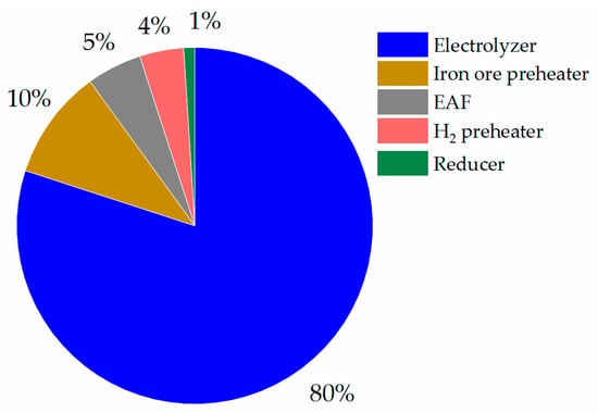
Figure 11.
Energy consumption of HDRI-EAF in %.
3.3. Optimization of Reduction Process in a Laboratory Condition
After identifying the key input values of the HDRI-EAF process, taking into consideration the energy and mass balance calculation, the conditions for the experiment were decided and outlined in Table 6.

Table 6.
Condition of experiments.
Fe2O3, or red iron ore, in the form of powder with the composition mentioned in Table 6, was used as a feedstock in all experiments. As for the reducing gas (H2), 54 kg of H2 was required for the reduction of 1428 kg of Fe2O3 based on the data provided in Table 5. Since the nominal value of the mass flow controller is 20 SLM and the flow rate nominal value ranges between 5 and 100% [], it is necessary to convert grams of H2 into liters of H2 to set the correct experimental condition. If 1 mole of any gas occupies 22.4 L of volume at the standard temperature and pressure, then 1 g of Fe2O3 will require 0.037 g of H2 or 0.423 L/min of H2. To conduct experiments under the minimum (5%) H2 flow rate control range, which is 1 L/min of H2, the above-mentioned and converted value of 0.4235 L/min must be at least 1 L/min. Thus, 2.36 g of Fe2O3 will be required for conducting experiments under 1 L/min of H2 flow rate. Aside from the reducing gas, N2 was used for heating and cooling the feedstock until the designated experimental condition was reached. After each residence time, N2 was used for cooling the product to avoid the deoxidation of sponge iron (Fe). The validation of the reducibility of Fe2O3 with H2 was confirmed through an experiment by using N2 at 800 °C, 0.001 MPa, and 5 min of heating time at the designated temperature. As a result of the validation experiment, the mass of the feedstock did not change significantly (2.36 g → 2.35 g). Subsequently, all other experiments were conducted with the different conditions outlined in Table 6. It was also assumed that in all samples, impurities are neglected, and any reduction yield exceeding 100% is attributed to these neglected impurities.
3.3.1. Experiment with Reducing Iron Ore at Different Temperatures, Each with a 5-min Residence Time
Initial experiments were conducted with temperature conditions of 750 °C, 760 °C, 770 °C, 780 °C, 790 °C, and 800 °C, with a residence time of 5 min each. These experiments aimed to understand the range of experimental conditions to focus on in future research investigations. Figure 12 depicts the outcome of the experiments, where the reduction efficiency in all cases was consistently near 100%. The most attractive case was an experiment of reducing iron ore under the condition of 770 °C and 5 min of residence time, highlighted with a red dot in Figure 12. Previously published papers reported an approximate 23% reduction yield of LKAB-KPRS iron ore pellets (diameter = 14 mm) with H2 with the experimental conditions of 770 °C, a 5-min residence time, 4.7 g of mass, H2/He (60/40 vol.), and a 2 L/min mass flow of gases. The reduction yield increased from 14% to 25% in the temperature profile between 600 °C and 950 °C. In the case of reducing CVRD-DR pellets (diameter = 14 mm), the reduction yield with a 5-min residence time, 4.7 g of mass, H2/He (60/40 vol.), and 2 L/min mass flow of gases in the temperature profile between 600 °C and 950 °C ranged from approximately 10% to 20% []. Heidari et al. [,] presented their findings on reducing iron ore with 100% hydrogen on a laboratory-scale, finding that a 95% reduction degree can be achieved in 300 s or 5 min at 700 °C. Their findings closely align with the results found in this study. Cavaliere et al. [] found the reduction of iron ore at 1000 °C and 1 bar resulted in nearly 100% reduction after 15 min of residence time. A reason for the parabolic behavior of the figure is related to chemical and physical mechanisms, namely an insufficient (short) residence time at an elevated temperature, which can lead to constraints for hydrogen to diffuse through the entire particle and form sintering of iron. This, in turn, decreases the surface area available for the reaction with hydrogen. As a result, the yield of reduction will be reduced. Similar phenomena are also highlighted in studies by Bhaskar et al. [,,].
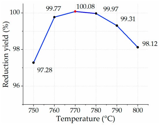
Figure 12.
Yield of reduction in 5 min with H2 at different temperature profiles.
3.3.2. Experiment with Reducing Iron Ore at Different Temperatures, Each with a 10-min Residence Time
The next batch of experiments was conducted with a residence time of 10 min in each temperature profile. The yield of reduction in each temperature profile was close to nearly full reduction (Figure 13). It is important to mention that the stoichiometric value of consumed hydrogen per unit of iron ore was calculated as 1 L/min for reducing 2.36 g of Fe2O3. In this case, the mass flow of hydrogen was 10 L per reduction scenario.
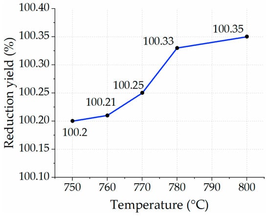
Figure 13.
Yield of reduction in 10 min with H2 at different temperature profiles.
Despite assuming pure iron ore in this study, the results show a yield of reduction slightly exceeding 100%. The obtained numbers prove that there are no significant changes in each temperature profile despite a twofold increase in residence time.
In a previous study that reduced iron ore at 800 °C, some data were provided, stating that the highest reduction yield (85%) could be achieved after reaching a 50-min residence time. Afterward, no other significant reduction was observed. Initial reduction values with a 10-min residence time demonstrated more than 80% of the reduction yield []. The outcomes suggest that a different approach or condition is required to reach a 100% reduction yield. The findings of the current study provided significant value in the optimization of the process. Another case study of reducing iron ore pellets from two different manufacturers provided 50% and 40% reduction yields at 770 °C with 4.7 g of feedstock mass and a 2 L/min of H2/He (60/40 vol.) mass flow []. Despite almost the same conditions, the outcomes were lower than the ones found based on experiments in this study.
3.3.3. Experiment with Reducing Fe2O3 at Different Temperatures, Each with a 15-min Residence Time
The next case involved increasing the residence time from 10 min to 15 min for each temperature profile. Figure 14 depicts the yield of reduction of iron ore for each temperature profile ranging from 750 °C to 800 °C. The yield of reduction remained unchanged and demonstrated a full reduction in all cases except for the case of 750 °C, where the yield of reduction nearly approached 100%. Since the residence time is a threefold increase from the first scenario, the specific consumption of hydrogen was also 15 times increased compared to the stochiometric values. Findings of Sohn [] with the 100% H2 reduction condition of Fe2O3 provided different conversion yields, namely 95%, 96%, 85%, 85%, and 100% at 500 °C, 600 °C, 700 °C, 800 °C, and 900 °C, respectively. At 800 °C, the reduction of Fe2O3 with a residence time of 15 min did not differ from the one at 700 °C. The results are similar to the ones found in this study’s reduction case with a residence time of 15 min.
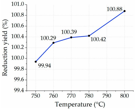
Figure 14.
Yield of reduction in 15 min with H2 at different temperature profiles.
3.3.4. Experiment with Reducing Fe2O3 at 770 °C, Each with Varying Residence Times
After running experiments for each cluster of residence time, including 5, 10, and 15 min, it was decided to continue with further detailed experiments at 770 °C, which was selected due to the full reduction yield and lower temperature points compared to other scenarios. Figure 15 illustrates the yield of reduction at each residence time (i.e., 1, 2, 3, 3.5, 4, 5, and 7 min). After observing the outcomes of all experiments, the yield of reduction with the residence times of 5 and 7 min demonstrated nearly the same values as the yield of reduction with residence times of 10 and 15 min. As for the reduction processes with residence times of 1 min, 2 min, 3 min, 4 min, and 5 min, the yields were 14.9%, 55.59%, 75.5%, 85.71%, and 90.36%, respectively. Despite a 100.08% yield of reduction for the residence time of 5 min, doubling the amount of Fe2O3 mass did not help to reach full reduction for each feedstock sample, resulting in 87.76% in the first sample and 86.14% in the second sample of the experiment. Therefore, the next strategy was to double the number of samples with a residence time of 7 min instead of 5 min. As a result, the reduction yield achieved nearly full reduction at the levels of 99.70% in the first sample and 99.33% in the second sample, as indicated with a red dot in Figure 15. If the number of the same samples is doubled and the reduction yield of each sample achieves a near 100% reduction yield, the specific consumption of hydrogen under the optimal reduction process can be 3.5 L/min of hydrogen for reducing one unit of the feedstock, which means the real value is 3.5 times more than the stochiometric value. To understand the behavior of the reduction process with a 3.5-min residence time, another experiment was conducted at 770 °C with a single sample under the condition of 100% H2 supply, which showed an 85.71% reduction yield and is indicated with a red dot in Figure 15. These findings can be compared to a previous study by Wagner et al. [], which reached a reduction degree of nearly 90% in iron ore with 100% H2 at 800 °C within 3.5 min or 210 s. Another temperature profile at 700 °C showed a 70% yield of reduction within 210 s [,]. As for the outcome of this study and the experiment at 770 °C with two identical feedstocks under the condition of a 100% H2 reducing agent, a residence time of 7 min demonstrated the most optimal reduction yield. As a result, the findings in terms of the reduction time are equivalent to the one with 3.5 min per single unit of the feedstock.
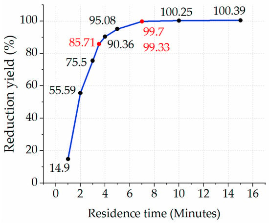
Figure 15.
Yield of reduction of Fe2O3 at T = 770 °C within a residence time ranged between 1 and 15 min.
3.4. Levelized Cost of Production of HDRI-EAF Route
In addition to the optimization of the HDRI-EAF process, the evaluation of the cost of steel is also an important factor in the successful commercialization and implementation of this route in developed and emerging countries.
Table 7 shows a summary of the investment costs, illustrating the capital expenditure of the HDRI-EAF route. The case of Uzbekistan was applied in this study by using the available costs of each unit and materials. In the economic evaluations, additional units were added to the calculations, such as hydrogen storage and compression units.

Table 7.
HDRI-EAF capital expenditure specification.
Table 8 shows details of operational expenditure of HDRI-EAF route.

Table 8.
HDRI-EAF operational expenditure specification.
Based on the latest reports, the cost of stack replacement is about 45% of the total capital expenditure of the alkaline electrolyzer unit []. In economic evaluation studies, the technical specifications of the Tebinbulak DRI-EAF project (under development) have been selected for the case study in the current investigations []. Due to limited data from the selected case study, additional technical specifications of DRI-EAF have been used for the current study []. Current available alkaline electrolyzer [,,] with 2020 efficiency has a stack with a lifetime period of 60,000.00–80,000.00 h, and the electrolyzer units in the current study are operated during sunshine hours with an overall 51,100.00 h in the 20 years of HDRI-EAF’s lifespan period. Operational expenditures on stack replacement for the electrolyzer were not included in the calculations of the LCOP. There are some assumptions applied in the LCOP calculations. For example, the Uzbek commodity exchange does not have several products on sale, including iron ore, electrolyzer, hydrogen fuel, ultrapure water, hydrogen compression, storage units, shaft furnaces, EAF, etc.
Calculations on the economic indicators of the route, in the case of the Tebinbulak project (under development) [] in Uzbekistan, with an annual 3 million tons of liquid steel production, resulted in 633.68 USD/tls of the LCOP. The original project did not include hydrogen fuel as a reducing agent, but in this study, green hydrogen was introduced instead of the designated fossil fuel. Figure 16 shows the capital and operational expenditure of the HDRI-EAF route based on applying electrolyzer units with a 2020 efficiency (53 kWh/kgH2). Due to limited data from the ongoing project in the Tebinbulak area, it was not possible to acquire the project-based capital and operational expenditures on the shaft furnace, electric arc furnace, and local iron ore price. As a result, the HDRI-EAF route with an electrolyzer of 2020 efficiency requires an overall investment of USD 3,752,345,559.85 or 1250.78 USD/tls and 1,369,478,570.51 USD/year of operational costs.
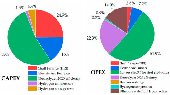
Figure 16.
Capital and operational expenditure of HDRI-EAF with electrolyzer unit of 2020 efficiency.
In the case of economic analysis of the HDRI-EAF route with an electrolyzer of 2030 efficiency (45 kWh/kgH2), it accounted for 606.30 USD/tls of the LCOP (Figure 17). In this route, with an electrolyzer of 2030 efficiency, the total investment requires USD 3,452,113,899.61 or 1150.70 USD/tls and an operational expenditure of 1,323,453,056.99 USD/year. In the calculations, solar PV electricity with a 0.027 USD/kWh rate was used for producing hydrogen with an electrolyzer.
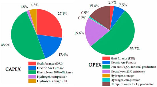
Figure 17.
Capital and operational expenditure of HDRI-EAF with electrolyzer unit of 2030 efficiency.
Taking into account the LCOP in two cases, it ranged between 606.30 USD/tls and 633.68 USD/tls for the case of Uzbekistan, while conventional steel production at Uzmetkombinat in Bekabad city, Uzbekistan, provided a LCOP of the finished product at 406 USD/tls [].
3.5. Optimized Operation of 100% Hydrogen-Fired Gas Turbine Model
In this section, the results of optimization strategies for the 100% hydrogen-fired gas turbine cycle were described based on the simulation model developed using Aspen HYSYS v 8.8 and Ansys Chemkin Pro 2019 R1 software tools. Table 9 shows the main results of the mass stream of the model.

Table 9.
Material stream of 100% hydrogen-fired gas turbine model developed on Aspen HYSYS.
Table 10 includes the energy flows of the model. In the model, the total flow of the inlet stream accounted for 8,739,123.33 kcal/h or 10,156.80 kW. The system’s energy balance was also closed.

Table 10.
Energy balance of 100% hydrogen-fired gas turbine model developed on Aspen HYSYS.
In terms of finding the optimized condition for the operation of the 100% hydrogen-fired gas turbine unit, Figure 18 shows different electric efficiencies at different power outputs of the 100% hydrogen-fired gas turbine in comparison with the benchmark power output based on the 100% natural gas-fired gas turbine cycle. The main optimization criterion in the target model was staying within the range of the inlet temperature of the gas turbine unit. Analyzing all findings, the condition with a 1400 °C inlet temperature resulted in a 34.10% electric efficiency (93.73% achievability of the reference model power output of 7600.00 kW), 7123.86 kW power output, 930.00 kg/h mass flow of hydrogen, and 85,000.00 kg/h mass flow of air. As mentioned earlier, there are no CO2 emissions in the exhaust gases of the model. On the other hand, the cycle presents challenges with NOx emissions. Figure 19 shows the fluctuation of the NOx emissions at three points, namely the perfectly stirred reactors (PSR) 1, 2, and 3. The ultimate value of NOx at 15% O2 is rated at 50.82 ppm, which is higher than the required benchmark (9.9 ppm at 15% O2) set by the gas turbine manufacturer []. However, the 50.82 ppm of NOx emissions at 15% O2 is still lower than the latest findings of Banihabib et al. [], which reported 62 ppm of NOx emissions at 15% O2. Therefore, the result of the lowest NOx emissions at 15% O2 is still significant and novel.
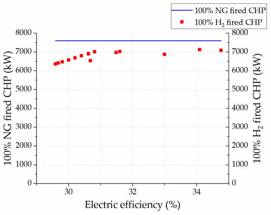
Figure 18.
Comparison of natural and hydrogen gas-fired cycle power outputs over fluctuating electric efficiency of target model.
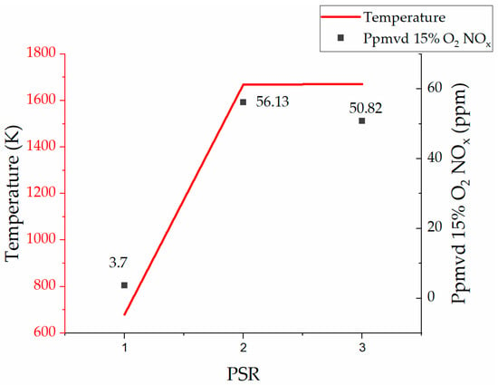
Figure 19.
NOx emissions vs. temperature in three zones (PSRs 1,2, and 3).
Regarding the economic indicators of the model, the calculations included capital and operating expenditures. Table 11 provides details of the capital expenditures for the successful operation of the 100% hydrogen-fired gas turbine unit.

Table 11.
Capital expenditure of 100% hydrogen-fired gas turbine with a 7.6 MW output capacity.
As Uzbekistan has an average of 7 h of sunshine daily [], it is necessary to consider the required hydrogen storage capacity (15,810.00 kg of H2 per 7 h or 2,258.57 kg of H2 per hour) for storing the necessary amount of hydrogen to use during the unavailable sunshine operation hours of the CHP plant. Taking into consideration the necessary amount of hydrogen production, it is required to have an electrolyzer unit with a 168.99 MW capacity with an efficiency of 2020, or a 143.48 MW capacity with an efficiency of 2030. From the stoichiometry of the reaction mentioned in Equation (26), 9 kg of ultrapure water is required to produce 1 kg of hydrogen. In practice, 10–13 kg of water is required to produce 1 kg of hydrogen, taking into consideration the losses in the electrolyzer unit []. Therefore, for the above-mentioned 100% hydrogen-fired gas turbine unit, it is necessary to prepare 12,090.00 kg of ultrapure water per hour.
Table 12 provides details of the operational expenditure for running the 100% hydrogen-fired gas turbine with a 7.6 MW installed capacity.

Table 12.
Operational expenditure of 100% hydrogen-fired gas turbine with a 7.6 MW capacity.
Taking into consideration the condition of operating the existing gas turbine unit with a 7123.86 kW output power capacity using hydrogen as the main fuel, including an electrolyzer unit of 2020 efficiency, ultrapure water for hydrogen production, hydrogen compressor, and storage, the LCOE accounted for 0.81 USD/kWh. In comparison, the LCOE of the first solar PV plant in Uzbekistan accounted for 0.027 USD/kWh []. The reason for such a high LCOE from the 100% hydrogen-fired gas turbine is the additional capital and operational expenditures, namely electrolyzer units, hydrogen compressors, storage tanks, and feed materials for hydrogen production. A study by Skordoulias et al. also found the LCOE of 100% hydrogen-fired gas turbines to be in a similar range []. Figure 20 and Figure 21 show a breakdown of the capital and operational expenditures of the 100% hydrogen-fired gas turbine with an emphasis on the costs related to electrolyzer units with different efficiencies (i.e., 2020 and 2030). In the cost breakdown of CAPEX with an electrolyzer of 2020 efficiency, the highest capital expenditure (75.1%) belongs to the procurement of electrolyzer units, and the overall investment cost was 14,223.77 USD/kW. Therefore, the electricity consumed by the electrolyzer with an efficiency of 2020 accounted for 67.3% of the cost breakdown of OPEX. On the other hand, the electrolyzer of 2030 showed lower expenditures, including 71.9% of the electrolyzer share in CAPEX and 63.6% of the electrolyzer operational expenditures. The overall investment cost of the system was 12,612.45 USD/kW. Both cases are far from the overall CAPEX of the reference 100% natural gas-fired gas turbine unit, which is 2183.00 USD/kW. The reason for such high expenditure costs related to the electrolyzer units’ CAPEX and OPEX, is the operation of electrolyzer units only during sunshine hours (7 h) and the generation of green hydrogen.
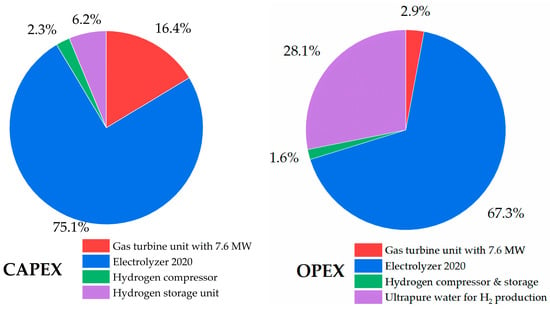
Figure 20.
CAPEX and OPEX (electrolyzer efficiency 2020) of 100% hydrogen-fired gas turbine.
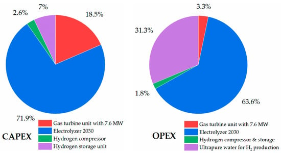
Figure 21.
CAPEX and OPEX (electrolyzer efficiency 2030) of 100% hydrogen-fired gas turbine.
A comparison of the findings in both cases, applying hydrogen fuel for the full (100%) replacement of fossil fuel consumption in the steel and power sectors, gives a good understanding of the future perspectives of each sector. As the HDRI-EAF route’s LCOP ranged between 606.30 USD/tls and 633.68 USD/tls, the impact of 1 kg of used hydrogen on the total hourly cost of steel production ranged between USD 9.34 and 9.76 per kg of used hydrogen. In the case of the 100% hydrogen-fired gas turbine unit, the LCOE ranged between 0.72 and 0.80 USD/kWh, and the impact of 1 kg of hydrogen fuel on the total hourly produced electricity amounted to a value in the range of USD 5.53 to 6.18 per kg of consumed hydrogen.
The investment cost to produce 1 kg of hydrogen fuel in the HDRI-EAF route and 100% hydrogen-fired gas turbine unit in the cases of electrolyzer units with 2020 and 2030 efficiency features require a 91,116.42 USD/kgH2 capacity and 78,773.57 USD/kgH2 capacity, respectively, meaning the steel sector has a more attractive final product cost compared to the power sector.
The HDRI-EAF route with electrolyzer units of 2020 and 2030 efficiency rates requires 4420.07 MW and 3752.89 MW, respectively, while the 100% hydrogen-fired gas turbine needs 168.99 MW of electrolyzer with a 2020 efficiency and 143.48 MW in the case of the one with a 2030 efficiency. The largest alkaline electrolyzer-based hydrogen-producing plant with a 260 MW capacity, recently installed in Xinjiang, northwest China [], has failed in its stable operation due to fluctuations in renewable energy output, meaning that from a technical and financial viewpoint, it would be difficult to deploy hydrogen units for the prospective Tebinbulak DRI-EAF route at this time. However, it is the first DRI-EAF route-based metallurgical plant in Uzbekistan, and there are no other small-scale DRI-EAF routes in the country. In regard to applying hydrogen fuel in the power sector of Uzbekistan, there are several applicable gas turbines in existing power plants with capacities in the range of 7.6 MW to 650 MW []. Another positive development in this direction is ACWA Power launching the first green hydrogen project in Uzbekistan with a capacity of 3000.00 tons of hydrogen production per year. In addition, ACWA Power is developing another pilot project for producing 3000.00 tons of green ammonia per year and a subsequent project to produce 500,000.00 tons of green ammonia per year []. As the current study’s 100% hydrogen-fired gas turbine model requires 4643.67 tons of hydrogen per year for the demands of the CHP, these sources of hydrogen and ammonia can be used in the power sector to replace fossil fuels. Future scenarios for 2030 from previous studies by Giacomazzi et al. [,] also mention the possibility of reducing NOx emissions below 25 ppmvd at 15% O2 with 100% hydrogen combustion. Moreover, an issue related to the flashback phenomena of hydrogen combustion in a gas turbine must also be considered before transforming the existing gas turbine units from conventional fuel to hydrogen [], and lastly, because hydrogen storage under high pressure in this study showed high costs, including expenses on the compression unit, ammonia-based hydrogen storage can also be considered as a potential option based on previous studies [,,].
4. Conclusions
This research work aims to compare the effects of applying hydrogen fuel in the steel and power sectors of Uzbekistan. Firstly, the energy and mass balance of the hydrogen direct-reduction iron ore–electric arc furnace (HDRI-EAF), analysis of energy consumption indicators of the process, and laboratory-scale experiments for optimizing the yield of reduction with an emphasis on residence time, temperature, and mass flow of hydrogen, were investigated. Secondly, optimized conditions of the energy and mass balance of the 100% hydrogen-fired gas turbine unit with a 7.6 MW installed capacity were found by analyzing the chemical kinetics in the hydrogen combustion process. Thirdly, the levelized cost of the production of steel, in the example of the prospective Tebinbulak DRI-EAF route-based metallurgical plant in Uzbekistan, was conducted to compare with the levelized cost of the electricity of the 100% hydrogen-fired gas turbine unit at Fergana’s combined heat and power (CHP) plant in Uzbekistan. After discussing all the results from two different hydrogen-based industrial sectors, the following research findings are summarized as follows:
- The total specific energy consumption of the HDRI-EAF route, as determined through the energy and mass balance calculations, yielded a significantly lower value (2679.69 kWh/tls) compared to the previous findings in other studies.
- Optimizing iron ore reduction with hydrogen fuel in a laboratory condition experiment provided valuable expertise in handling hydrogen fuel in the process. This optimization resulted in a high reduction yield at a lower temperature (770 °C) and within a limited residence time (7 min for two identical samples or 3.5 min per sample) compared to the experimental conditions of previous studies.
- In the case of the 100% hydrogen-fired gas turbine, several simulations on the Aspen HYSYS v 8.8 software resulted in finding optimal conditions with an energy and mass balance for the cycle. The newly developed cycle was able to achieve nearly 93.73% of the installed capacity (7.6 MW) of the gas turbine’s output power rate.
- As for the emissions from the newly developed 100% hydrogen-fired gas turbine cycle, no CO2 emissions were observed. Regarding the NOx emissions at 15% O2, the findings (50.82 ppmvd) exceeded the manufacturer’s regulation (9.9 ppmvd) but remained lower than those demonstrated by a recently introduced novel 100% hydrogen-fired micro gas turbine (62 ppmvd).
- In the economic assessment of the HDRI-EAF route, two scenarios, each with different efficiency levels of electrolyzer units (2020 and 2030), have been investigated. The results show a lower levelized cost of production (LCOP) of steel, ranging from 606.30 USD/tls to 633.68 USD/tls, compared to recently conducted studies on economic analysis of the HDRI-EAF route (which reported values from 622 USD/tls to 722 USD/tls).
- The 100% hydrogen-fired gas turbine resulted in a levelized cost of electricity (LCOE) ranging from 0.72 USD/kWh to 0.80 USD/kWh with hydrogen production onsite, or 0.46 USD/kWh LCOE without hydrogen production onsite, and instead procuring hydrogen from outside at 3 USD/kgH2. This falls within a similar range to previous studies (from 0.50 USD/kWh to 0.75 USD/kWh). However, in comparison with the LCOE (from 0.027 USD/kWh to 0.08 USD/kWh) of conventional power plants in Uzbekistan, there is a significant cost difference that must be reduced in the future.
- A comparative analysis of the LCOP of the HDRI-EAF route and the LCOE of a 100% hydrogen-fired gas turbine provided a clear picture of the capital and operational expenditures of each system. The effect of 1 kg of hydrogen was higher in the case of the steel sector (from USD 9.34 to 9.76 per kg of used hydrogen) and lower in the case of the power sector (USD from 5.53 to 6.18 per kg of consumed hydrogen). The capacities of required electrolyzer units and the availability of a wide range of applicable technologies pointed to the power sector’s transformation from fossil fuels to hydrogen fuel in the short term. In regard to prioritizing the power sector rather than the steel manufacturing sector, various aspects of the power sector, such as several existing gas turbine units in Uzbekistan with a wide range of capacity and significant CO2 emissions, are emphasized.
Author Contributions
Conceptualization, K.A. and Z.A.; methodology, K.A., Z.A. and W.K.; investigation, K.A.; writing—original draft preparation, K.A.; visualization, K.A.; project administration, K.A. and L.H.A.; writing—review and editing, Z.A., L.H.A., T.D.X. and W.K.; resources, T.D.X.; supervision, T.D.X., L.H.A. and W.K.; funding acquisition, T.D.X. All authors have read and agreed to the published version of the manuscript.
Funding
This research received no external funding.
Data Availability Statement
The data used in this study are available upon request from the corresponding author. The data are not publicly available due to restrictions of each plant owner.
Acknowledgments
The authors express their gratitude to the JDS project for providing funding to implement this study and experiments. Additionally, the first author appreciates the suggestions from Rittanupap Thavorn and Akihiro Ueda in the analyses of hydrogen-based reduction and combustion kinetics, respectively.
Conflicts of Interest
The authors declare no conflicts of interest.
Abbreviations
| BF-BOF | Blast furnace–basic oxygen furnace |
| CB | Combustion boat |
| EAF | Electric arc furnace |
| Fe2O3 | Hematite |
| Fe3O4 | Magnetite |
| FeO | Wüstite |
| Fe | Sponge iron |
| g | Gram |
| Hin | Enthalpy of mass going into the reactor or unit |
| Hout | Enthalpy of mass going out from the reactor or unit |
| HDRI | Hydrogen direct reduction iron |
| HYFOR | Hydrogen-based fine-ore reduction |
| J | Joule |
| kWh | Kilowatt hours |
| L/min | Litre per minute |
| Min | Mass going into the reactor or unit |
| Mout | Mass going out from the reactor or unit |
| Mol | Mole |
| ppmvd | Parts per million, by volume on a dry basis |
| SEC | Specific energy consumption |
| SLM | Standard liter per minute |
| tls | Ton of liquid steel |
References
- Bhaskar, A.; Assadi, M.; Nikpey Somehsaraei, H.A.; Somehsaraei, H.N. Decarbonization of the Iron and Steel Industry with Direct Reduction of Iron Ore with Green Hydrogen. Energies 2020, 13, 758. [Google Scholar] [CrossRef]
- Basson, E. 2022 World Steel in Figures; World Steel Association: Brussels, Belgium, 2022. [Google Scholar]
- Holappa, L. A General Vision for Reduction of Energy Consumption and CO2 Emissions from the Steel Industry. Metals 2020, 10, 1117. [Google Scholar] [CrossRef]
- Small, M. Direct Reduction of Iron-Ore. J. Met. 1981, 33, 67–75. [Google Scholar] [CrossRef]
- Digiesi, S.; Mummolo, G.; Vitti, M.S. Minimum Emissions Configuration of a Green Energy-Steel System: An Analytical Model. Energies 2022, 15, 3324. [Google Scholar] [CrossRef]
- de la Pena, B.; Iriondo, A.; Galletebeitia, A.; Gutierrez, A.; Rodriguez, J.; Lluvia, I.; Vicente, A.B. Toward the Decarbonization of the Steel Sector: Development of an Artificial Intelligence Model Based on Hyperspectral Imaging at Fully Automated Scrap Characterization for Material Upgrading Operations. Steel Res. Int. 2023, 94, 2200943. [Google Scholar] [CrossRef]
- Eisl, R.; Hochwimmer, M.; Oppeneiger, C.; Buchberger, D. Hydrogen Based Direct Iron Ore Reduction Plant Simulation. BHM 2022, 167, 92–98. [Google Scholar] [CrossRef]
- Yamashita, S. Hyfor Pilot Plant Starts Operation—Next Step in Carbon-Free Hydrogen Reduction Steelmaking. Available online: https://www.primetals.com/jp/%E3%83%97%E3%83%AC%E3%82%B9-%E3%83%A1%E3%83%87%E3%82%A3%E3%82%A2/%E6%9C%80%E6%96%B0%E6%83%85%E5%A0%B1/hyfor-pilot-plant-under-operation-the-next-step-for-carbon-free-hydrogen-based-direct-reduction-is-done (accessed on 12 December 2023).
- Spreitzer, D.; Wurm, J.; Hiebl, B.; Rein, N.; Wolfinger, T.; Sterrer, W.; Fleischanderl, A. HYFOR—Hydrogen-Based Fine-Ore Reduction. Available online: https://www.mhi.co.jp/technology/review/pdf/e592/e592070.pdf (accessed on 16 December 2023).
- Heidari, A.; Niknahad, N.; Iljana, M.; Fabritius, T.A. A Review on the Kinetics of Iron Ore Reduction by Hydrogen. Materials 2021, 14, 7540. [Google Scholar] [CrossRef]
- Ma, K.; Deng, J.; Wang, G.; Zhou, Q.I.; Xu, J.K.H.; Xu, J. Utilization and Impacts of Hydrogen in the Ironmaking Processes: A review from lab-scale basics to industrial practices. Int. J. Hydrogen Energy 2021, 46, 26646–26664. [Google Scholar] [CrossRef]
- Hessels, C.J.M.; Homan, T.A.M.; Deen, N.G.; Tang, Y.C.J.M.; Tang, Y. Reduction Kinetics of Combusted Iron Powder Using Hydrogen. Powder Technol. 2022, 407, 117540. [Google Scholar] [CrossRef]
- Patisson, F.; Mirgaux, O.F. Hydrogen Ironmaking: How It Works. Metals 2020, 10, 922. [Google Scholar] [CrossRef]
- Spreitzer, D.; Schenk, J.D. Reduction of Iron Oxides with Hydrogen—A Review. Steel Res. Int. 2019, 90, 1900108. [Google Scholar] [CrossRef]
- Yi, S.-H.; Lee, W.-J.; Lee, Y.-S.; Kim, W.-H.S.H.; Kim, W.-H. Hydrogen-Based Reduction Ironmaking Process and Conversion Technology. Korean J. Met. Mater. 2021, 59, 41–53. [Google Scholar] [CrossRef]
- Patisson, F.; Mirgaux, O.; Birat, J.-P.F. Hydrogen steelmaking. Part 1: Physical chemistry and process metallurgy. Matér. Tech. 2021, 109, 303. [Google Scholar] [CrossRef]
- Ishii, K.; Akiyama, T.; Kashiwaya, Y.; Kondo, S.-i. The Rates of Reduction of Iron-Ore and Water-Gas Shift Reaction. Hokkaido Univ. Fac. Eng. Bull. 1986, 17, 1–13. [Google Scholar]
- Wagner, D.; Devisme, O.; Patisson, F.; Ablitzer, D. A Laboratory Study of the Reduction of Iron Oxides by Hydrogen. Sohn Int. Symp. 2006, 2, 111–120. [Google Scholar]
- Zakeri, A.; Coley, K.S.; Tafaghodi, L.A. Hydrogen-Based Direct Reduction of Iron Oxides: A Review on the Influence of Impurities. Sustainability 2023, 15, 13047. [Google Scholar] [CrossRef]
- Zheng, H.; Schenk, J.; Daghagheleh, O.; Taferner, B.H. Parameter Optimization for Hydrogen-Induced Fluidized Bed Reduction of Magnetite Iron Ore Fines. Metals 2023, 13, 339. [Google Scholar] [CrossRef]
- Sohn, H.Y.; Roy, S.H.Y.; Roy, S. Development of a Moving-Bed Ironmaking Process for Direct Gaseous Reduction of Iron Ore Concentrate. Metals 2022, 12, 1889. [Google Scholar] [CrossRef]
- Pei, M.; Petäjäniemi, M.; Regnell, A.; Wijk, O.M. Toward a Fossil Free Future with HYBRIT: Development of Iron and Steelmaking Technology in Sweden and Finland. Metals 2020, 10, 972. [Google Scholar] [CrossRef]
- Echterhof, T. Review on the Use of Alternative Carbon Sources in EAF Steelmaking. Metals 2021, 11, 222. [Google Scholar] [CrossRef]
- Gielen, D.; Saygin, D.; Taibi, E.; Birat, J.D. Renewables-based Decarbonization and Relocation of Iron and Steel Making: A Case Study. J. Ind. Ecol. 2020, 24, 1113–1125. [Google Scholar] [CrossRef]
- Vogl, V.; Åhman, M.; Nilsson, L.J.V.; Ahman, M.; Nilsson, L.J. Assessment of Hydrogen Direct Reduction for Fossil-free Steelmaking. J. Clean. Prod. 2018, 203, 736–745. [Google Scholar] [CrossRef]
- Bhaskar, A.; Assadi, M.; Somehsaraei, H.N.A.; Somehsaraei, H.N. Can Methane Pyrolysis Based Hydrogen Production Lead to the Decarbonisation of Iron and Steel Industry? Energy Convers. Manag. X 2021, 10, 100079. [Google Scholar] [CrossRef]
- Bhaskar, A.; Abhishek, R.; Assadi, M.; Somehesaraei, H.N.A.; Somehesaraei, H.N. Decarbonizing Primary Steel Production: Techno-Economic Assessment of a Hydrogen Based Green Steel Production Plant in Norway. J. Clean. Prod. 2022, 350, 131339. [Google Scholar] [CrossRef]
- IEA. CO2 Emissions in 2022. Available online: https://www.iea.org/reports/co2-emissions-in-2022 (accessed on 27 December 2023).
- Skabelund, B.B.; Jenkins, C.D.; Stechel, E.B.; Milcarek, R.J.B.B.; Milcarek, R.J. Thermodynamic and Emission Analysis of a Hydrogen/methane Fueled Gas Turbine. Energy Convers. Manag. X 2023, 19, 100394. [Google Scholar] [CrossRef]
- Nose, M.; Kawakami, T.; Nakamura, S.; Kuroki, H.; Kataoka, M.; Yuri, M. Development of Hydrogen/Ammonia Firing Gas Turbine for Decarbonized Society; Mitsubishi Heavy Industries: Tokyo, Japan, 2021. [Google Scholar]
- Matsumoto, T.; Kawakami, T.; Takeishi, H.; Miura, K.; Nakamura, S.; Yuri, M. Development of Hydrogen/Ammonia-Firing Gas Turbine for Carbon Neutrality—Mitsubishi Heavy Industries Technical Review; Mitsubishi Heavy Industries: Tokyo, Japan, 2022; p. 13. [Google Scholar]
- MHI.LTD. Hydrogen Power Generation Handbook, 2nd ed.; MHI.LTD Energy Systems: Yokohama, Japan, 2021; Volume METP-01GT02E1-A-0, (1.0)21-09, ZEG. [Google Scholar]
- Cecere, D.; Giacomazzi, E.; Di Nardo, A.; Calchetti, G.D. Gas Turbine Combustion Technologies for Hydrogen Blends. Energies 2023, 16, 6829. [Google Scholar] [CrossRef]
- Giacomazzi, E.; Troiani, G.; Di Nardo, A.; Calchetti, G.; Cecere, D.; Messina, G.; Carpenella, S.E. Hydrogen Combustion: Features and Barriers to Its Exploitation in the Energy Transition. Energies 2023, 16, 7174. [Google Scholar] [CrossRef]
- Noble, D.; Wu, D.; Emerson, B.; Sheppard, S.; Lieuwen, T.; Angello, L.D. Assessment of Current Capabilities and Near-Term Availability of Hydrogen-Fired Gas Turbines Considering a Low-Carbon Future. J. Eng. Gas Turb. Power 2021, 143, 041002. [Google Scholar] [CrossRef]
- Langston, L.S. As the Turbine Turns… Hydrogen-Fueled Gas Turbines. Mech. Eng. 2019, 141, 52–54. [Google Scholar] [CrossRef]
- Alikulov, K.; Xuan Tran, D. O-17 Achievement of theoretical hydrogen consumption in Hydrogen Direct Reduction of Iron Ore. In Proceedings of the 18th Biomass Science Conference, Maebashi, Japan, 30 November–2 December 2022; pp. 37–38. [Google Scholar]
- Boretti, A. The Perspective of Hydrogen Direct Reduction of Iron. J. Clean. Prod. 2023, 429, 139585. [Google Scholar] [CrossRef]
- Felder, R.M.; Rousseau, R.W. Elementary Principles of Chemical Processes, 3rd ed.; John Wiley: Chichester, NY, USA, 2000; p. xxvi. 675p. [Google Scholar]
- Smith, J.M.; Van Ness, H.C.; Abbott, M.M. Introduction to Chemical Engineering Thermodynamics, 7th ed.; McGraw-Hill: Boston, MA, USA, 2005; p. xviii. 817p. [Google Scholar]
- National Institute of Standards and Technology (U.S.). NIST Chemistry Webbook, June 2005 ed.; National Institute of Standards and Technology: Washington, DC, USA, 2005; p. electronic text.
- Dutta, S.K.; Ghosh, A.S.K.; Ghosh, A. A New Method for Measurement of Degree of Reduction in Composite Pellets of Iron Ore with Carbonaceous Matter. ISIJ Int. 1993, 33, 1104–1106. [Google Scholar] [CrossRef][Green Version]
- Li, S.; Zhang, H.; Nie, J.; Dewil, R.; Baeyens, J.; Deng, Y.S. The Direct Reduction of Iron Ore with Hydrogen. Sustainability 2021, 13, 8866. [Google Scholar] [CrossRef]
- Toktarova, A.; Karlsson, I.; Rootzén, J.; Göransson, L.; Odenberger, M.; Johnsson, F.A. Pathways for Low-Carbon Transition of the Steel Industry-A Swedish Case Study. Energies 2020, 13, 3840. [Google Scholar] [CrossRef]
- KHI. GPB80D. Available online: https://kga.com.my/wp-content/uploads/2020/10/GPB80D-200227.pdf (accessed on 22 November 2023).
- Fukutani, S.; Kunioshi, N.; Jinno, H.S. Mechanism of Combustion Reactions in Hydrogen-Air Premixed Flames. BCSJ 1990, 63, 2191–2198. [Google Scholar] [CrossRef]
- CHEMKIN®Software. CHEMKIN-Pro 15112 Tutorials Manual, Reaction Design; San Diego, CA, USA, 2011. Available online: https://personal.ems.psu.edu/~radovic/ChemKin_Tutorial_2-3-7.pdf (accessed on 10 December 2023).
- ScienceFact.net. Brayton Cycle. Available online: https://www.sciencefacts.net/brayton-cycle.html (accessed on 22 September 2023).
- Campbell, J.M.; Hubbard, R.A. Gas Conditioning and Processing, 8th ed.; John M. Campbell and Company: Norman, OK, USA, 1966; p. xii. 440p. [Google Scholar]
- Gas Processors Suppliers Association. Engineering Data Book, 13th ed.; Gas Processors Suppliers Association: Tulsa, OK, USA, 2012. [Google Scholar]
- AspenTech. Aspen HYSYS—Process Utility Manager, version 8.8; 2015. Available online: https://www.aspentech.com/en/resources/press-releases/aspentech-unveils-aspenonert-version-8-8-software-to-help-manufacturers-achieve-opera2147495140 (accessed on 10 October 2023).
- Solar-Edition. What Is LCOE, Levelized Cost of Energy? The Concept Explained & Formula…. Available online: https://solaredition.com/what-is-lcoe/ (accessed on 24 October 2023).
- Banihabib, R.; Assadi, M.R. A Hydrogen-Fueled Micro Gas Turbine Unit for Carbon-Free Heat and Power Generation. Sustainability 2022, 14, 13305. [Google Scholar] [CrossRef]
- Banihabib, R.; Lingstädt, T.; Wersland, M.; Kutne, P.; Assadi, M. Development and Testing of a 100 kW Fuel-flexible Micro Gas Turbine Running on 100% Hydrogen. Int. J. Hydrogen Energy 2024, 49, 92–111. [Google Scholar] [CrossRef]
- Rechberger, K.; Spanlang, A.; Sasiain Conde, A.; Wolfmeir, H.; Harris, C.K. Green Hydrogen-Based Direct Reduction for Low-Carbon Steelmaking. Steel Res. Int. 2020, 91, 2000110. [Google Scholar] [CrossRef]
- Pimm, A.J.; Cockerill, T.T.; Gale, W.F.A.J.; Gale, W.F. Energy System Requirements of Fossil-free Steelmaking Using Hydrogen Direct Reduction. J. Clean. Prod. 2021, 312, 127665. [Google Scholar] [CrossRef]
- Souza Filho, I.R.; Springer, H.; Ma, Y.; Mahajan, A.; Da Silva, C.C.; Kulse, M.; Raabe, D.I.R.; Hauke, H.; Raabe, D. Green Steel at Its Crossroads: Hybrid Hydrogen-based Reduction of Iron Ores. J. Clean. Prod. 2022, 340, 130805. [Google Scholar] [CrossRef]
- FCON CO., LTD. Mass Flow Controller 1000 Series. Available online: http://www.fcon-inc.jp/en/en_MFC/1000/1000.html (accessed on 13 December 2023).
- Cavaliere, P.; Perrone, A.; Marsano, D.P. Effect of Reducing Atmosphere on the Direct Reduction of Iron Oxides Pellets. Powder Technol. 2023, 426, 118650. [Google Scholar] [CrossRef]
- Sarkar, A.; Chavan, V.; Pai, N.N.; Prakash, A.; Hazra, B.; Raut, P.; Sunilkumar, D.; Sivananda, C.; Kundu, S.; Nag, S.; et al. Reduction of Iron Ore Pellets: A Microstructural Perspective? Metall. Mater. Trans. A Phys. Metall. Mater. Sci. 2024, 55, 537–549. [Google Scholar] [CrossRef]
- Sohn, H.Y. Energy Consumption and CO2 Emissions in Ironmaking and Development of a Novel Flash Technology. Metals 2020, 10, 54. [Google Scholar] [CrossRef]
- Melnikov, Y. Sustainable Hydrogen Production Pathways in Eastern Europe, the Caucasus and Central Asia; United Nations Economic Comission for Europe: Geneva, Switzerland, 2023; p. 110. [Google Scholar]
- IRENA. Making the Breakthrough: Green Hydrogen Policies and Technology Costs; International Renewable Energy Agency: Masdar, United Arab Emirates, 2021. [Google Scholar]
- IRENA. Green Hydrogen Cost Reduction: Scaling up Electrolysers to Meet the 1.5 °C Climate Goal; International Renewable Energy Agency: Abu Dhabi, United Arab Emirates, 2020; pp. 1–103. ISBN 978-92-9260-295-6. [Google Scholar]
- Krishnan, S.; Koning, V.; Kramer, G.J. Present and future cost of alkaline and PEM electrolyser stacks. Int. J. Hydrogen Energy 2023, 48, 32313–32330. [Google Scholar] [CrossRef]
- Kruger, A.; Krüger, A.; Andersson, J.; Grönkvist, S.; Cornell, A. Integration of water electrolysis for fossil-free steel production. Int. J. Hydrogen Energy 2020, 45, 29966–29977. [Google Scholar] [CrossRef]
- Feng, Z. Economically Viable Intermediate to Long Duration Hydrogen Energy Storage Solutions for Fossil Fueled Assets; WE New Energy Inc.: Knoxville, TN, USA, 2022. [Google Scholar]
- Christensen, A. Assessment of Hydrogen Production Costs from Electrolysis: United States and Europe; International Council on Clean Transportation: Washington, DC, USA, 2020; Available online: https://theicct.org (accessed on 5 January 2024).
- Kolisnichenko, V. Iron Ore Prices on the Dalian Exchange Reached $138/t. Available online: https://gmk.center/en/news/iron-ore-prices-on-the-dalian-exchange-reached-138-t/ (accessed on 6 January 2024).
- Monitor-Deloitte. Fueling the Future of Mobility: Hydrogen Electrolyzers; Monitor Deloitte: Cambridge, MA, USA, 2021; p. 27. Available online: https://www2.deloitte.com/ (accessed on 6 January 2024).
- Flagma. Highly Purified Deionized Water. Available online: https://flagma.uz/ru/deionizirovannaya-voda-vysokoy-stepeni-ochistki-o1931903.html (accessed on 7 January 2024).
- Cavaliere, P. Direct Reduced Iron: Most Efficient Technologies for Greenhouse Emissions Abatement. In Clean Ironmaking and Steelmaking Processes; Springer: Cham, Switzerland, 2019; pp. 419–484. [Google Scholar] [CrossRef]
- Elsheikh, H.; Eveloy, V.H. Renewable hydrogen based direct iron ore reduction and steel making with grid assistance. Energy Convers. Manag. 2023, 297, 117544. [Google Scholar] [CrossRef]
- Anderson, G.; Ma, J.; Mirzoev, T.; Zhu, L.; Zhunussova, K. A Low-Carbon Future for the Middle East and Central Asia: What Are the Options? IMF Departmental Papers; International Monetary Fund: Washington, DC, USA, 2022; p. 52. [Google Scholar]
- IRENA. Energy Profile—Uzbekistan. Available online: https://www.irena.org/-/media/Files/IRENA/Agency/Statistics/Statistical_Profiles/Asia/Uzbekistan_Asia_RE_SP.pdf (accessed on 21 December 2023).
- EnterEngineering. Design of Tebinbulak Concentration Plant Is Approaching “the Home Stretch”. Available online: https://www.ent-en.com/en/page/publication/210 (accessed on 10 January 2024).
- Midrex. MIDREX® Direct Reduction Plants 2022 Operations Summary. Available online: https://www.midrex.com/tech-article/midrex-direct-reduction-plants-2022-operations-summary/ (accessed on 9 January 2024).
- Rolo, I.; Costa, V.A.F.; Brito, F.P. Hydrogen-Based Energy Systems: Current Technology Development Status, Opportunities and Challenges. Energies 2024, 17, 180. [Google Scholar] [CrossRef]
- Pirmatov, R.; Ahmedov, D.; Budey, T. Business Plan of JSC “UZMETKOMBINAT” for 2023; JSC “UZMETKOMBINAT”: Tashkent, Uzbekistan, 2022; pp. 1–33. Available online: www.uzbeksteel.uz (accessed on 12 January 2024).
- Meteonorm-8. Meteorological dataset of Uzbekistan. 2020. Available online: https://meteonorm.com/en/ (accessed on 6 January 2024).
- Eurowater. Water Treatment for Hydrogen Production: FAQ—Water Treatment and Hydrogen Production. Available online: https://www.eurowater.com/en/hydrogen-production#:~:text=89%25%20of%20the%20mass%20is,due%20to%20losses%20and%20inefficiencies (accessed on 6 January 2024).
- Skordoulias, N.; Koytsoumpa, E.I.; Karellas, S.N. Techno-economic evaluation of medium scale power to hydrogen to combined heat and power generation systems. Int. J. Hydrogen Energy 2022, 47, 26871–26890. [Google Scholar] [CrossRef]
- Collins, L. EXCLUSIVE | World’s Largest Green Hydrogen Project ‘Has Major Problems Due to Its Chinese Electrolysers’: BNEF. Available online: https://www.hydrogeninsight.com/production/exclusive-worlds-largest-green-hydrogen-project-has-major-problems-due-to-its-chinese-electrolysers-bnef/2-1-1566679 (accessed on 13 January 2024).
- JSC“TPP”. Business Plan of Joint-Stock Company “Thermal Power Plants” for 2023; Joint-Stock Company “Thermal Power Plants”: Tashkent, Uzbekistan, 2022; pp. 1–25. Available online: https://tpp.uz (accessed on 14 January 2024).
- Čučuk, A. ACWA Power Launches Uzbekistan’s First Green Hydrogen Project. Available online: https://www.offshore-energy.biz/acwa-power-launches-uzbekistans-first-green-hydrogen-project/ (accessed on 14 January 2024).
- Serbin, S.; Radchenko, M.; Pavlenko, A.; Burunsuz, K.; Radchenko, A.; Chen, D.S. Improving Ecological Efficiency of Gas Turbine Power System by Combusting Hydrogen and Hydrogen-Natural Gas Mixtures. Energies 2023, 16, 3618. [Google Scholar] [CrossRef]
- Aziz, M.; Wijayanta, A.T.; Nandiyanto, A.B.D.M.; Nandiyanto, A. Ammonia as Effective Hydrogen Storage: A Review on Production, Storage and Utilization. Energies 2020, 13, 3062. [Google Scholar] [CrossRef]
- Negro, V.; Noussan, M.; Chiaramonti, D.V. The Potential Role of Ammonia for Hydrogen Storage and Transport: A Critical Review of Challenges and Opportunities. Energies 2023, 16, 6192. [Google Scholar] [CrossRef]
- Hasan, M.H.; Mahlia, T.M.I.; Mofijur, M.; Rizwanul Fattah, I.M.; Handayani, F.; Ong, H.C.; Silitonga, A.S.M.H.; Mahlia, T.; Silitonga, A.S. A Comprehensive Review on the Recent Development of Ammonia as a Renewable Energy Carrier. Energies 2021, 14, 3732. [Google Scholar] [CrossRef]
Disclaimer/Publisher’s Note: The statements, opinions and data contained in all publications are solely those of the individual author(s) and contributor(s) and not of MDPI and/or the editor(s). MDPI and/or the editor(s) disclaim responsibility for any injury to people or property resulting from any ideas, methods, instructions or products referred to in the content. |
© 2024 by the authors. Licensee MDPI, Basel, Switzerland. This article is an open access article distributed under the terms and conditions of the Creative Commons Attribution (CC BY) license (https://creativecommons.org/licenses/by/4.0/).