Article

Budeanu’s Distortion Power Components Based on CPC Theory in Three-Phase Four-Wire Systems Supplied by Symmetrical Nonsinusoidal Voltage Waveforms

by
Zbigniew Sołjan
1,* and
Tomasz Popławski
2
1
Faculty of Electrical Engineering, Bialystok University of Technology, Wiejska 45D Street, 15-351 Białystok, Poland
2
Faculty of Electrical Engineering, Czestochowa University of Technology, Aleja Armii Krajowej 17, 42-200 Częstochowa, Poland
*
Author to whom correspondence should be addressed.
Energies 2024, 17(5), 1043; https://doi.org/10.3390/en17051043
Submission received: 30 January 2024 / Revised: 18 February 2024 / Accepted: 21 February 2024 / Published: 22 February 2024
(This article belongs to the Section F: Electrical Engineering)

Abstract

:
Budeanu’s power theory, in its fundamental version, describes single-phase sinusoidal and nonsinusoidal systems. Over time, this elementary description has been extended to three-phase three-wire and four-wire systems, regardless of power conditions. Initially, three-phase systems were considered as three independent single-phase systems. A distinct approach was introduced by Czarnecki in his power theory (Currents’ Physical Components—CPC). The energy description and reference of the equivalent parameters of the load are comprehensive in the context of three-phase systems; Czarnecki treats such systems as a whole. This paper introduces a mathematical model to expand the basic Budeanu theory for three-phase four-wire (3-p 4-w) systems powered by symmetrical and nonsinusoidal voltage sources. The proposed approach is based on mutual elements between the fundamental Budeanu theory and the CPC theory, treating the 3-p 4-w system as a whole. In the extended Budeanu theory model, equations for the Budeanu reactive current and the Budeanu complemented reactive current are derived. The article also demonstrates their orthogonality concerning the remaining components, indicating that each of the seven components can exist independently of the others. Furthermore, in the extended Budeanu theory, it is possible to identify which equivalent parameters of the load are responsible for the individual currents (powers) and which components are associated with the total distortion power proposed by Budeanu in 1927. All of the calculations were performed in Matlab/Simulink 2023b software.

1. Introduction

The exploration of energy properties in the frequency domain began in 1927 with C. I. Budeanu [1,2]. This power theory, initially proposed by Budeanu, has undergone extensive development by numerous authors, evolving into increasingly sophisticated mathematical formulations [3,4,5,6,7]. However, it was revealed that Budeanu’s power theory misinterprets the physical phenomena occurring in systems, as demonstrated by L. S. Czarnecki in a 1987 publication [8]. The conceptual error primarily concerns the interpretation of reactive power in systems powered by a nonsinusoidal but periodic voltage source. Budeanu defined reactive power in such systems as the sum of the amplitudes of the alternating components of the instantaneous power of the harmonic current and voltage. Additionally, distortion power (DB) was introduced as the sum of active power (P) and reactive power (QB) to apparent power (S), without establishing a clear connection to any physical phenomena in the system [2,8,9,10]. In the Budeanu theory, it is possible to calculate the active power of the entire system and the RMS value of the active current. However, determining the reactance parameters of elements providing compensation and symmetry in systems supplied with sinusoidal or nonsinusoidal voltage, whether the voltage source is symmetrical or asymmetrical, was not feasible until the publication of papers [11,12]. In the paper [11], a description of the current components of a single-phase load supplied with a nonsinusoidal voltage was presented with the equivalent parameters of the load. The publication [12] introduced the possibility of reactance compensation based on the extended Budeanu theory.
The foundational concept that paved the way for the development of the Budeanu theory is the CPC theory proposed by Czarnecki. Czarnecki’s approach is rooted in the frequency domain. Initially, the author of CPC considered both single-phase systems with sinusoidal and nonsinusoidal voltages [2,13,14,15]. Subsequently, the theory progressed to encompass three-phase three-wire (3-p 3-w) systems [14,15,16,17,18,19] and three-phase four-wire (3-p 4-w) systems [20,21,22,23,24,25,26,27,28,29,30]. The evolution of the theory involved describing each of these three-phase systems for both symmetrical supply [2,13,14,15,21,22,28,29,30] and asymmetrical supply [18,19,20,23,24,25,26,27]. Moreover, all these systems have detailed descriptions covering ideal reactance compensation [15,16,18,19,22,25,26], as well as the minimization of reactance compensation [20,24,31,32,33]. It is noteworthy that not only Czarnecki and the authors of this publication utilize the CPC theory; researchers worldwide are adapting it for various purposes. These include applications such as active filters, control algorithms for switching power electronic keys, or the determination of physical components of voltage in three-phase systems [34,35,36,37,38,39].
While the inaccuracy of the Budeanu theory was demonstrated in the publication [8], unfortunately, it continues to be utilized in universities and implemented in practical applications, such as in electricity meters or power quality parameter analyzers.
The development of the Budeanu theory, as presented by the authors, opens up opportunities for applications in various aspects of everyday life for both individual and industrial consumers. Despite the widespread adoption of LED lighting globally [40,41,42,43], it remains common practice to use the Budeanu theory when matching passive systems to compensate for reactive power, without considering the Budeanu distortion power. As highlighted in publications [11,12] and discussed in this article, a portion of the reactive power and the entire imbalance can be identified within the Budeanu distortion power. Renewable Energy Sources (RES) represent another domain where an accurate description of energy properties is crucial. Due to the possibility of single-phase and three-phase unbalanced systems, renewable sources contribute to increased load asymmetry [44,45,46,47,48] and the total harmonic distortion coefficient of voltage (THDU). Consequently, there is a growing need for a more precise depiction of the energy properties of such systems. The third rapidly developing area is wireless power transmission (WPT) [49,50,51,52,53,54]. These systems utilize inductors for energy transfer and are primarily based on the power supply system available at a given location. This makes such systems sensitive to various types of asymmetry and distortion in both the supply voltage and the load itself. As is evident, a correct and consistent power theory can play a crucial role in diagnosing problems within a system accurately and cost-effectively enhancing its operational characteristics.
The article is divided into nine sections. Section 1 provides a literature review related to the Budeanu theory and the CPC theory, along with their practical applications in constructing passive and active compensators. Additionally, this section includes information about the potential application of the extended Budeanu theory in various practical scenarios, such as constructing compensators, lighting systems, wireless energy transmission, or implementing algorithms in electricity meters. Section 2 presents a mathematical model describing the CPC theory in three-phase four-wire systems, where the voltage source is symmetrical, and the waveforms generated by the source are distorted. Section 3 comprises a presentation of traditional equations used to calculate line currents in three-phase systems (Ohm’s law and Kirchhoff’s law) and a description of the fundamental Budeanu theory. Section 4 focuses on presenting the mathematical model in the extended Budeanu theory for three-phase four-wire systems with nonsinusoidal and symmetrical power sources. This section also introduces the mutual elements in the CPC theory and the extended Budeanu theory. Section 5 discusses the second step in extending the Budeanu theory, which involves relating equivalent load parameters and the resulting currents’ components. Section 6 demonstrates the orthogonality between individual components in the extended Budeanu theory. Section 7 provides a theoretical illustration, based on the mathematical model from Section 4, showcasing the steps involved in calculating the individual parameters of the load. Section 8 summarizes and discusses the previous sections, with a primary focus on Budeanu distortion power. Finally, Section 9 serves as a conclusion, summarizing the scientific results obtained and presenting potential future directions for the development or extension of the Budeanu theory.

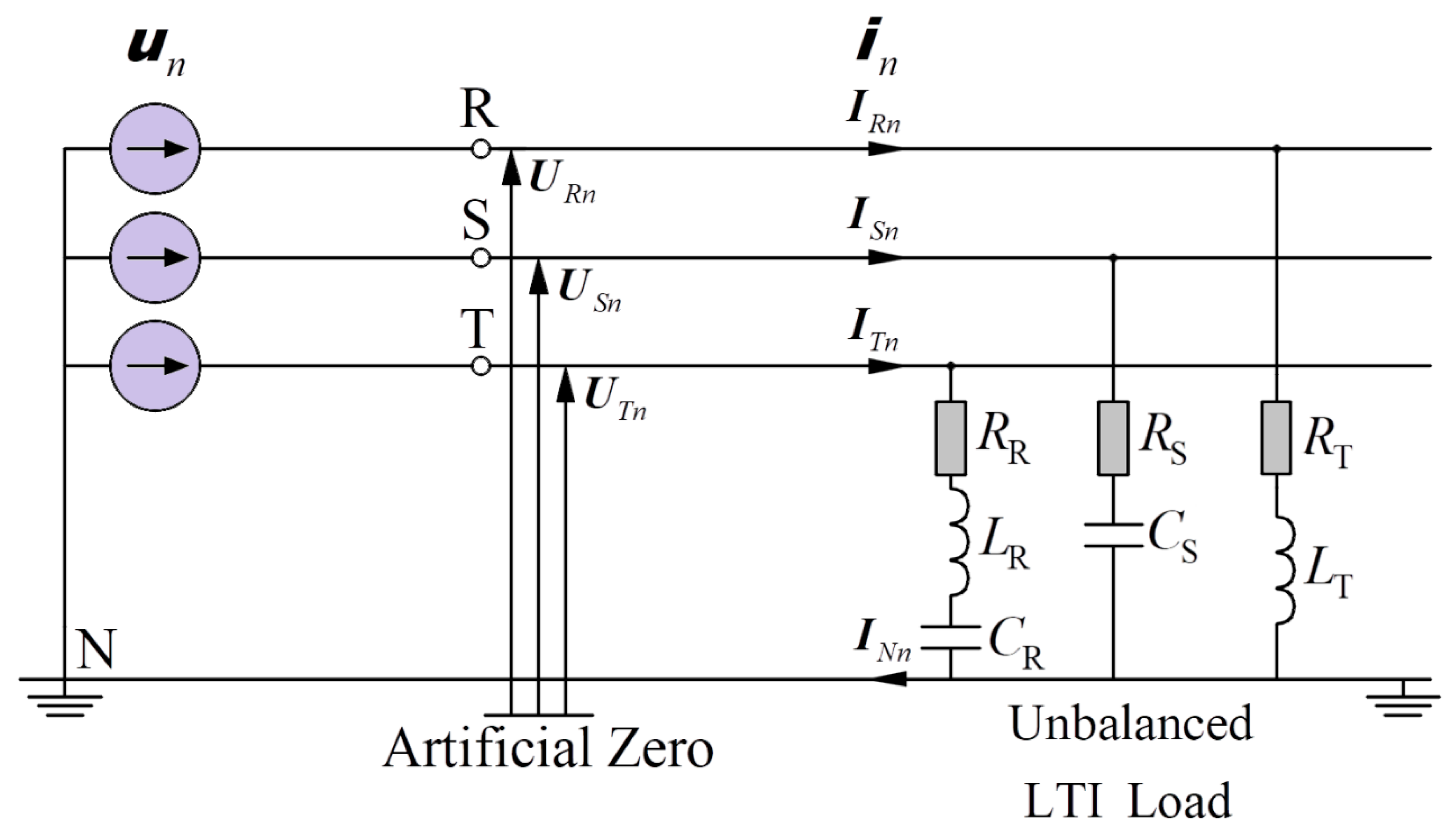
2. Currents’ Physical Components (CPC) Theory for 3-Phase 4-Wire Nonsinusoidal Symmetrical Systems

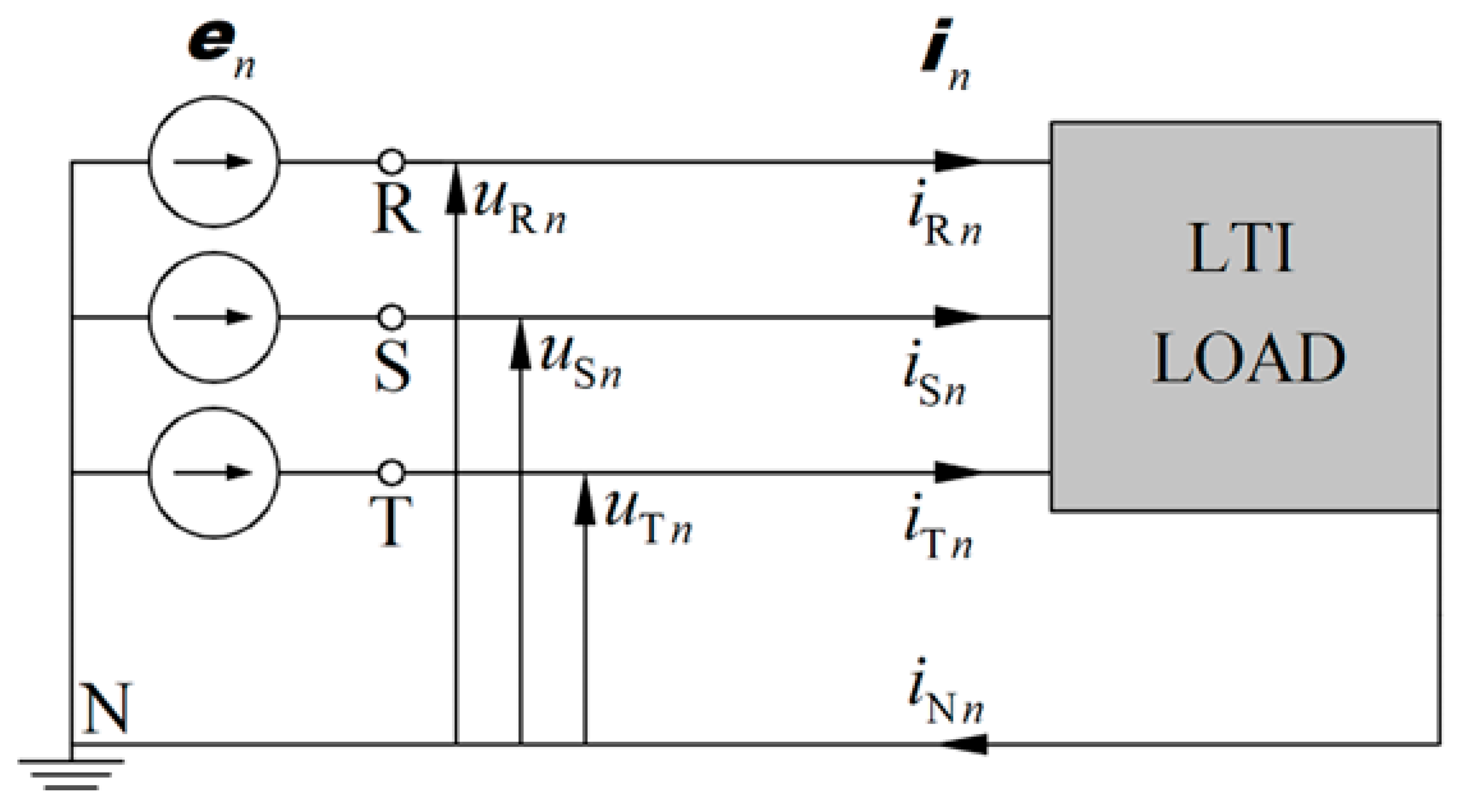
A voltage source in a power system can be a harmonics-generating source (see Figure 1).
The vector of nonsinusoidal voltages supplying the LTI (Linear Time-invariant) load can be written as follows [21,22]:
u ( t ) = [ u R ( t ) u S ( t ) u T ( t ) ] = 2 Re n N [ U R n U S n U T n ] e j n ω 1 t = 2 Re n N U n e j n ω 1 t
where U n —vector of complex RMS (CRMS) value of the voltage harmonic, and n —harmonic order.
The vector of line currents can be written identically:
i ( t ) = [ i R ( t ) i S ( t ) i T ( t ) ] = 2 Re n N [ I R n I S n I T n ] e j n ω 1 t = 2 Re n N I n e j n ω 1 t
where I n —vector of complex RMS (CRMS) value of the current harmonic.
From the active power P, the equivalent conductance of the full system can be defined, namely:
G e = n N P n n N ( U R n 2 + U S n 2 + U T n 2 ) = P u 2
The equivalent conductance determines the active current i a , the waveform of which is described by the equation:
i a = G e u = 2 Re n N G e U n e j n ω 1 t
The three-phase RMS value of the active current i a is
i a = G e u = P u
Based on Equation (3) and the equivalent conductances for the individual harmonics, the scattered current i s is determined, the waveform of which takes the following form:
i s = 2 Re n N ( G n G e ) U n e j n ω 1 t
The three-phase RMS value of the scattered current i s is
i s = n N [ ( G n G e ) 2 u n 2 ]
By using the equivalent susceptances of the individual harmonics, the reactive current waveform i r can be defined:
i r = 2 Re n N j B n U n e j n ω 1 t
The three-phase RMS value of the reactive current i r is
i r = n N [ ( B n ) 2 u n 2 ]
The overall unbalanced current i u can be expressed as
i ( i a + i s + i r ) = i i b = i u
The unbalanced current waveform i u is
i u = 2 Re n N I u n e j n ω 1 t = 2 Re n N ( I n ( I a n + I s n + I r n ) ) e j n ω 1 t = 2 Re n N ( I n ( G e + ( G n G e ) + j B n ) U n ) e j n ω 1 t
Therefore, after the transformation, the load current i is expressed by the following equation:
i = i a + i s + i r + i u
The three-phase RMS value of the load current i is
i 2 = i a 2 + i s 2 + i r 2 + i u 2
The entire unbalanced current i u can be decomposed into three symmetrical components as follows:
i u = i u p + i u n + i u z
The decomposition of the unbalanced current into symmetrical components is based on the use of the equivalent admittance of the entire three-phase system:
Y e n = G e n + j B e n = 1 3 ( Y R n + Y S n + Y T n )
Unbalanced admittance of the positive sequence:
Y u n p = 1 3 [ ( Y R n + α β Y S n + α * β * Y T n ) Y e n ( 1 + α β + α * β * ) ]
Unbalanced admittance of the negative sequence:
Y u n n = 1 3 [ ( Y R n + α * β Y S n + α β * Y T n ) Y e n ( 1 + α * β + α β * ) ]
Unbalanced admittance of the zero sequence:
Y u n z = 1 3 [ ( Y R n + β Y S n + β * Y T n ) Y e n ( 1 + β + β * ) ]
where the generalized coefficient β is
β = ( α * ) n = { 1 for   n = 3 k α * for   n = 3 k + 1 α for   n = 3 k 1
After the transformations, the current waveform of the unbalanced current of the positive sequence i u p is
i u p = 2 Re n N I u n p e j n ω 1 t = 2 Re n N Y u n p U n e j n ω 1 t = 2 Re n N Y u n p 1 p U R n e j n ω 1 t
The three-phase RMS value of the unbalanced current of the positive sequence i u p is
i u p = 3 n N Y u n p U R n
The waveform of the unbalanced current of the negative sequence i u n is
i u n = 2 Re n N I u n n e j n ω 1 t = 2 Re n N Y u n n U n e j n ω 1 t = 2 Re n N Y u n n 1 n U R n e j n ω 1 t
The three-phase RMS value of the unbalanced current of the negative sequence i u n is
i u n = 3 n N Y u n n U R n
The waveform of the unbalanced current of the zero sequence i u z is
i u z = 2 Re n N I u n z e j n ω 1 t = 2 Re n N Y u n z U n e j n ω 1 t = 2 Re n N Y u n z 1 z U R n e j n ω 1 t
The three-phase RMS value of the unbalanced current of the zero sequence i u z is
i u z = 3 n N Y u n z U R n
Finally, the load current can include six orthogonal components:
i 2 = i a 2 + i s 2 + i r 2 + i u p 2 + i u n 2 + i u z 2
The power equation takes the following form:
S 2 = P 2 + Q 2 + D s 2 + D u p 2 + D u n 2 + D u z 2
where the apparent power S, calculated from the Buchholz apparent power formula [2,53], is
S = u i
The active power P is
P = u i a
The reactive power Q is
Q = u i r
The scattered power D s is
D s = u i s
The unbalanced power of the positive sequence D u p is
D u p = u i u p
The unbalanced power of the negative sequence D u n is
D u n = u i u n
The unbalanced power of the zero sequence D u z is
D u z = u i u z
The power factor λ is
λ = P S = P P 2 + Q 2 + D s 2 + D u p   2 + D u n   2 + D u z   2

3. Ohm’s and Kirchhoff’s Laws and Budeanu Theory

The line currents can be calculated based on Ohm’s law:
I R n = U R n Y R n I S n = U S n Y S n I T n = U T n Y T n
Based on Kirchhoff’s first law, the current in the neutral line is
I N n = I R n + I S n + I T n
The RMS values of the individual line currents are
I R = n N | I R n | 2 I S = n N | I S n | 2 I T = n N | I T n | 2
The three-phase RMS value of the load current is
i = I R 2 + I S 2 + I T 2
The approach to describing the energy properties of circuits comes from the description of power (initially for single-phase systems). The theory is also used to describe three-phase systems.
The active power P in an individual phase of a three-phase system can be written as follows:
P = n N U X n I X n cos φ X n
where X denotes the successive phase from the set {R, S, T}.
Identically, in Budeanu’s approach, the reactive power in an individual phase QB can be defined as
Q B = n N U X n I X n sin φ X n
“The response” to the difference between the apparent power S and the active power P and reactive power QB is the distortion power DB, which is expressed by the equation:
D B = S 2 P 2 + Q B 2
The description of the energy properties and power components in the original Budeanu theory stops with the relationships noted above.

4. Development of the Budeanu Theory for 3-Phase 4-Wire Nonsinusoidal Symmetrical Systems—Step I

Noting that the active power P in the CPC theory and the Budeanu theory are identical, the equivalent conductance of the overall system can be calculated (3), and thus:
G e = n N P n n N ( U R n 2 + U S n 2 + U T n 2 ) = P u 2 = G eB
From this, it is possible to determine the active current in the Budeanu theory, which will have an identical waveform and an identical three-phase RMS value as in the CPC theory:
i a = i aB i a = i aB
From the Budeanu reactive power relation (41), the equivalent susceptance B eB of the whole system can be found, namely:
B eB = n N Q n n N ( U R n 2 + U S n 2 + U T n 2 ) = Q B u 2
Based on this, the Budeanu reactive current i rB can be defined, the waveform of which takes the form:
i rB = 2 Re n N j B eB U n e j n ω 1 t
The three-phase RMS value of the Budeanu reactive current i rB is
i rB = | B eB | u = | Q B | u
It should be noted that the reactive current in CPC theory and the Budeanu reactive current are currents that are different* with respect to three-phase RMS value and waveform, namely:
i r i rB i r i rB
* is the situation in which both currents are identical. The reactive currents in the two approaches are identical if and only if the susceptance does not change with the harmonic order for both the capacitive and inductive nature of the load - condition in the equation (80).
To the first step of the extension of the Budeanu theory, the waveform of the distortion current must be added. However, it is not determined from the equivalent parameters of the load but only by the difference in the individual currents:
i dB = i ( i aB + i rB )
The three-phase RMS value of the Budeanu distortion current i dB is
i dB = D B u

5. Development of the Budeanu Theory for 3-Phase 4-Wire Nonsinusoidal Symmetrical Systems—Step II

Assumptions in developing the Budeanu theory for three-phase four-wire systems supplied with nonsinusoidal symmetrical voltage:
Point 1: The active currents in the two theories are equal to each other and are represented by identical equivalent load parameters—the equivalent conductance of the load.
Point 2: The scattered current from the CPC theory is kept and defined as in Equations (6) and (7).
Point 3: The unbalanced current of the positive sequence in the CPC theory remains and is defined as in Equations (20) and (21).
Point 4: The unbalanced current of the negative sequence in the CPC theory remains and is defined as in Equations (23) and (23).
Point 5: The unbalanced current of the zero sequence in the CPC theory remains and is defined as in Equations (24) and (25).
Point 6: Look more closely at the Budeanu reactive current—relations (45) and (46).
The value of the Budeanu reactive current (waveform and three-phase RMS value) is less than the value of the reactive current in the CPC theory. In order to find the missing value of the current in the Budeanu theory and to relate it to the equivalent parameter of the load (to give a physical interpretation), it is necessary to look at the equation for the scattered current in the CPC theory, which is the difference between the conductances of the individual harmonics and the equivalent conductance of the whole system, since G b n G e —describes the scattered current, so
B b n B eB describes the missing value of the Budeanu reactive current
From the susceptance of the individual harmonics and the equivalent susceptance of the entire system, we can determine the waveform of the Budeanu complemented reactive current i crB , which is
i crB = 2 Re n N [ j ( B n B eB ) ] U n e j n ω 1 t
The three-phase RMS value of the Budeanu complemented reactive current i crB is
i crB = n N [ ( B n B eB ) 2 u n 2 ]
In summary, the load current described by the extended Budeanu theory (a combination of the Budeanu theory and the Currents’ Physical Components theory), can have seven components:
i = i a + i s + i rB + i crB + i u p + i u n + i u z
These components are orthogonal; therefore:
i 2 = i a 2 + i s 2 + i rB 2 + i crB 2 + i u p 2 + i u n 2 + i u z 2
The power equation takes the following form:
S 2 = P 2 + D s 2 + Q B 2 + Q crB 2 + D u p 2 + D u n 2 + D u z 2
where the apparent power S, calculated from the Buchholz apparent power relation, is
S = u i
The active power P is
P = u i a
The Budeanu reactive power Q B is
Q B = u i rB
The Budeanu complemented reactive power Q crB is
Q Bd = u i crB
The scattered power D s is
D s = u i s
The unbalanced power of the positive sequence D u p is
D u p = u i u p
The unbalanced power of the negative sequence D u n is
D u n = u i u n
The unbalanced power of the zero sequence D u z is
D u z = u i u z
The power factor λ is
λ = P S = P P 2 + D s 2 + Q B 2 + Q crB 2 + D u p   2 + D u n   2 + D u z   2

6. Orthogonality of the Components in the Extended Budeanu Theory

Vectors are mutually orthogonal when the scalar product of the three-phase quantities [2,21,22] is zero:
( x , y ) = 1 T 0 T x ( t ) T · y ( t ) d t = 0
If the three-phase quantities are represented in the form of complex RMS values, namely:
x = 2 Re { X e j ω t } ,         y = 2 Re { Y e j ω t }
then their scalar product is equal to
( x , y ) = 2 T 0 T Re { X T e j ω t } Re { Y e j ω t } d t = Re { X T Y * }
All components in the original CPC theory are mutually orthogonal [21]. The question of the orthogonality of the individual components with respect to the Budeanu reactive current and the Budeanu complemented reactive current remains.
  • Orthogonality of the Budeanu reactive current and the active current:
    ( i rB , i a ) = Re n N I rB n T I a n * = Re n N ( j B eB U n ) T ( G e U n ) * = Re { j n N B eB G e u n 2 } = 0
  • Orthogonality of the Budeanu reactive current and the scattered current:
    ( i rB , i s ) = Re n N I rB n T I s n * = Re n N ( j B eB U n ) T [ ( G n G e ) U n ] * = Re { j n N B eB ( G n G e ) u n 2 } = 0
  • Orthogonality of the Budeanu complemented reactive current and the active current:
    ( i crB , i a ) = Re n N I crB n T I a n * = Re n N [ j ( B n B eB ) U n ] T ( G e U n ) * = Re { j n N 0 ( B n B eB ) G e u n 2 } = 0
  • Orthogonality of the Budeanu complemented reactive current and the scattered current:
    ( i crB , i s ) = Re n N I crB n T I s n * = Re n N [ j ( B n B eB ) U n ] T [ ( G n G e ) U n ] * = Re { j n N ( B n B eB ) ( G n G e ) u n 2 } = 0
  • Orthogonality of the Budeanu complemented reactive current and the Budeanu reactive current:
    ( i crB , i rB ) = Re n N I crB n T I rB n * =   Re n N [ j ( B n B eB ) U n ] T ( j B eB U n ) * = Re n N j 2 B eB * ( B n B eB ) u n 2 = B eB * ( n N B n u n 2 B eB n N u n 2 ) = B eB * ( Q Q ) = 0
  • Orthogonality of the Budeanu reactive current and the unbalanced current of the positive sequence:
    ( i rB , i u p ) = Re n N I rB n T I u n p * = Re n N ( j B eB U n ) T [ ( Y u n p 1 p ) U R n ] * = Re { j n N B eB ( Y u n p 1 p ) * U n T U R n * } = Re { j n N B eB ( Y u n p ) * U n U R n * × [ 1 + α * + α ] } = 0
  • Orthogonality of the Budeanu reactive current and the unbalanced current of the negative sequence:
    ( i rB , i u n ) = Re n N I rB n T I u n n * = Re n N ( j B eB U n ) T [ ( Y u n n 1 n ) U R n ] * = Re { j n N B eB ( Y u n n 1 n ) * U n T U R n * } = Re { j n N B eB ( Y u n n ) * U n U R n * × [ 1 + α + α * ] } = 0
  • Orthogonality of the Budeanu reactive current and the unbalanced current of the zero sequence:
    ( i rB , i u z ) = Re n N I rB n T I u n z * = Re n N ( j B eB U n ) T [ ( Y u n z 1 z ) U R n ] * = Re { j n N B eB ( Y u n z 1 z ) * U n T U R n * } = Re { j n N B eB ( Y u n z ) * U n U R n * × [ 1 + α * + α ] } = 0
  • Orthogonality of the Budeanu complemented reactive current and the unbalanced current of the positive sequence:
    ( i crB , i u p ) = Re n N I crB n T I u n p * = Re n N ( j ( B n B eB ) U n ) T [ ( Y u n p 1 p ) U R n ] * = Re { j n N ( B n B eB ) ( Y u n p 1 p ) * U n T U R n * } = Re { j n N ( B n B eB ) ( Y u n p ) * U n U R n * × [ 1 + α * + α ] } = 0
  • Orthogonality of the Budeanu complemented reactive current and the unbalanced current of the negative sequence:
    ( i crB , i u n ) = Re n N I crB n T I u n n * = Re n N ( j ( B n B eB ) U n ) T [ ( Y u n n 1 n ) U R n ] * = Re { j n N ( B n B eB ) ( Y u n n 1 n ) * U n T U R n * } = Re { j n N ( B n B eB ) ( Y u n n ) * U n U R n * × [ 1 + α + α * ] } = 0
  • Orthogonality of the Budeanu complemented reactive current and the unbalanced current of the zero sequence:
    ( i crB , i u z ) = Re n N I crB n T I u n z * = Re n N ( j ( B n B eB ) U n ) T [ ( Y u n z 1 z ) U R n ] * = Re { j n N ( B n B eB ) ( Y u n z 1 z ) * U n T U R n * } = Re { j n N ( B n B eB ) ( Y u n z ) * U n U R n * × [ 1 + α * + α ] } = 0

7. Theoretical Illustration
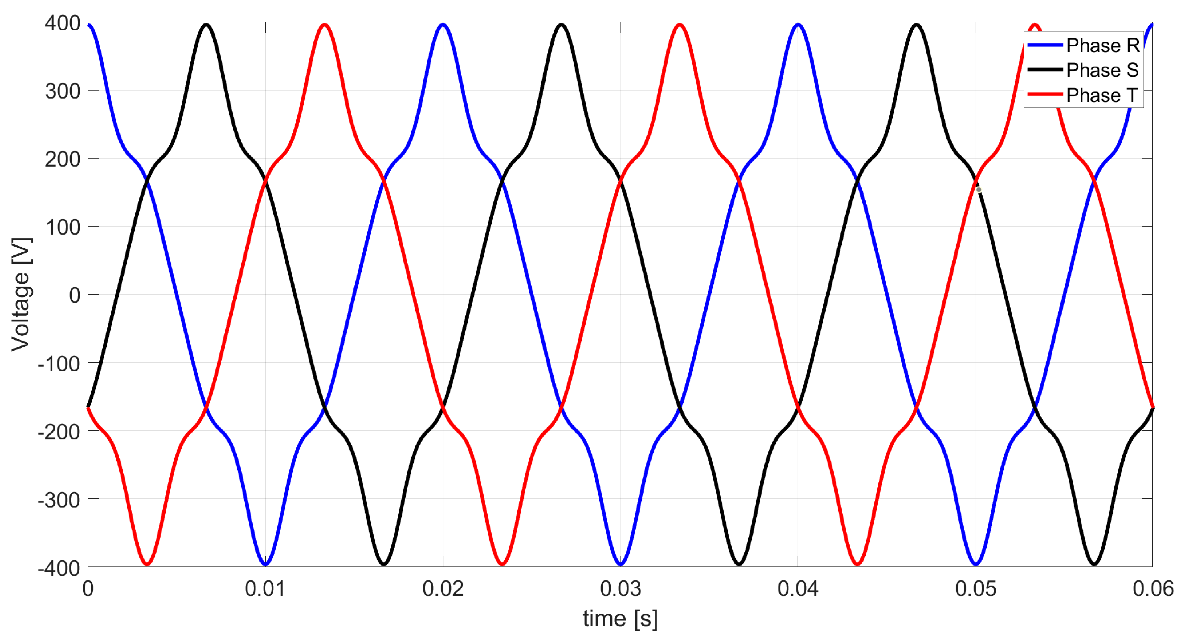
The system in Figure 2 is supplied from a nonsinusoidal symmetrical voltage source. The distorted voltage source, apart from the fundamental harmonic (230 V, 50 Hz), also generates harmonics of higher orders, i.e., n = 3, 5, 7 (3rd—15 V, 5th—25 V, 7th—10 V). The three-phase load is formed by linear elements in the form of resistance, inductive reactance and capacitive reactance, which were selected randomly, albeit with the load asymmetry. The system scheme is shown in Figure 2.
The resistance, inductive reactance and capacitive reactance values for the fundamental harmonic are listed in Table 1.
The waveform of the nonsinusoidal voltage at the R, S, T terminals is shown in Figure 3.
The three-phase RMS value of the nonsinusoidal supply voltage shown in Figure 3 is
u = 401.93   V
Table 2 presents the complex values of the admittances in the individual lines for each harmonic.
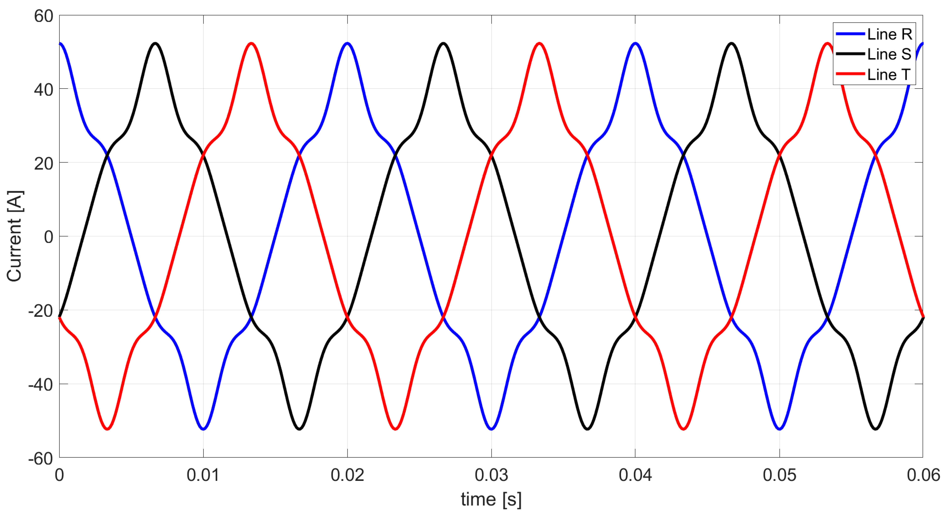
Based on Ohm’s law and Kirchhoff’s law, the complex values of the harmonic currents in the individual lines were calculated. Table 3 presents the resulting complex values of the nonsinusoidal line currents.
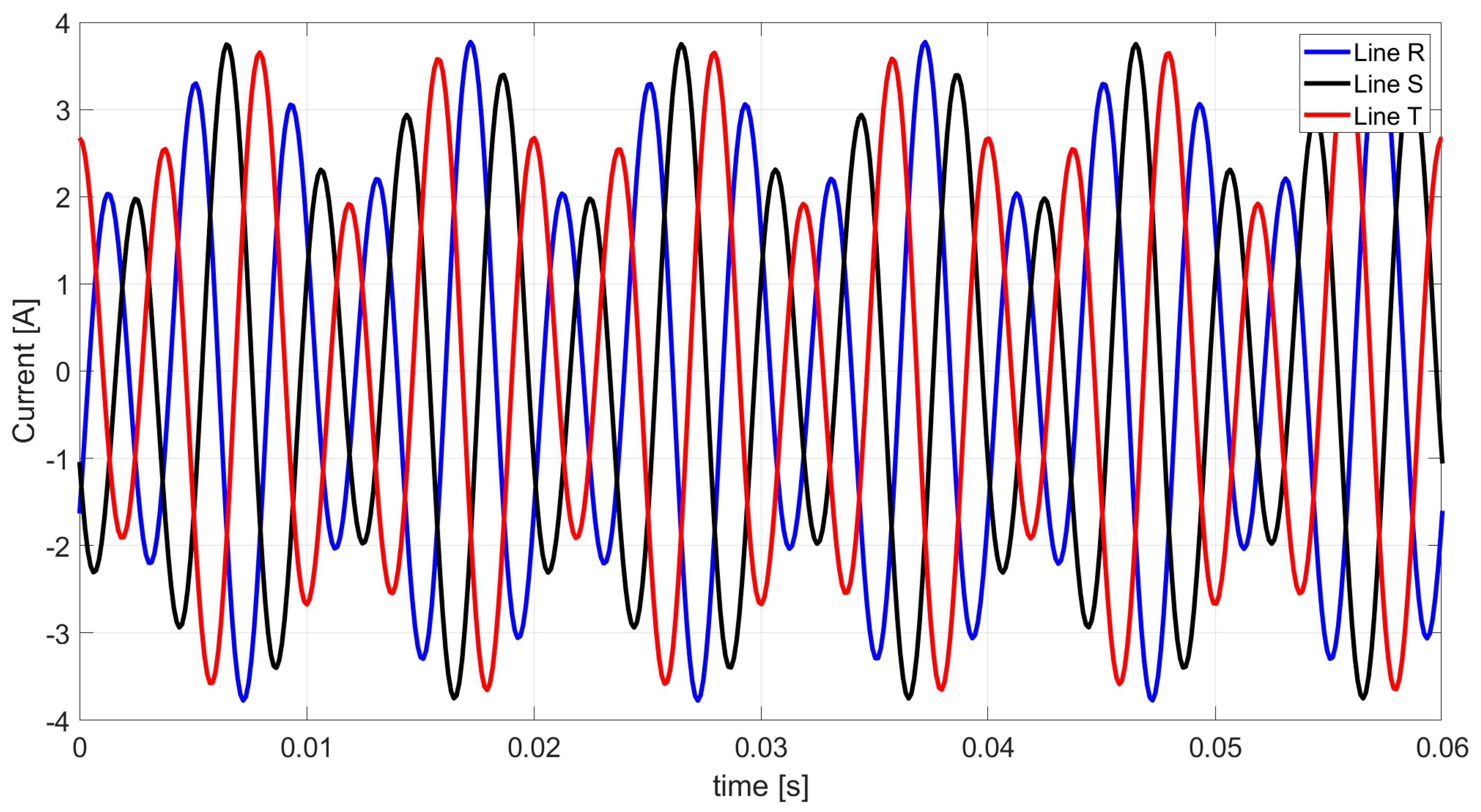
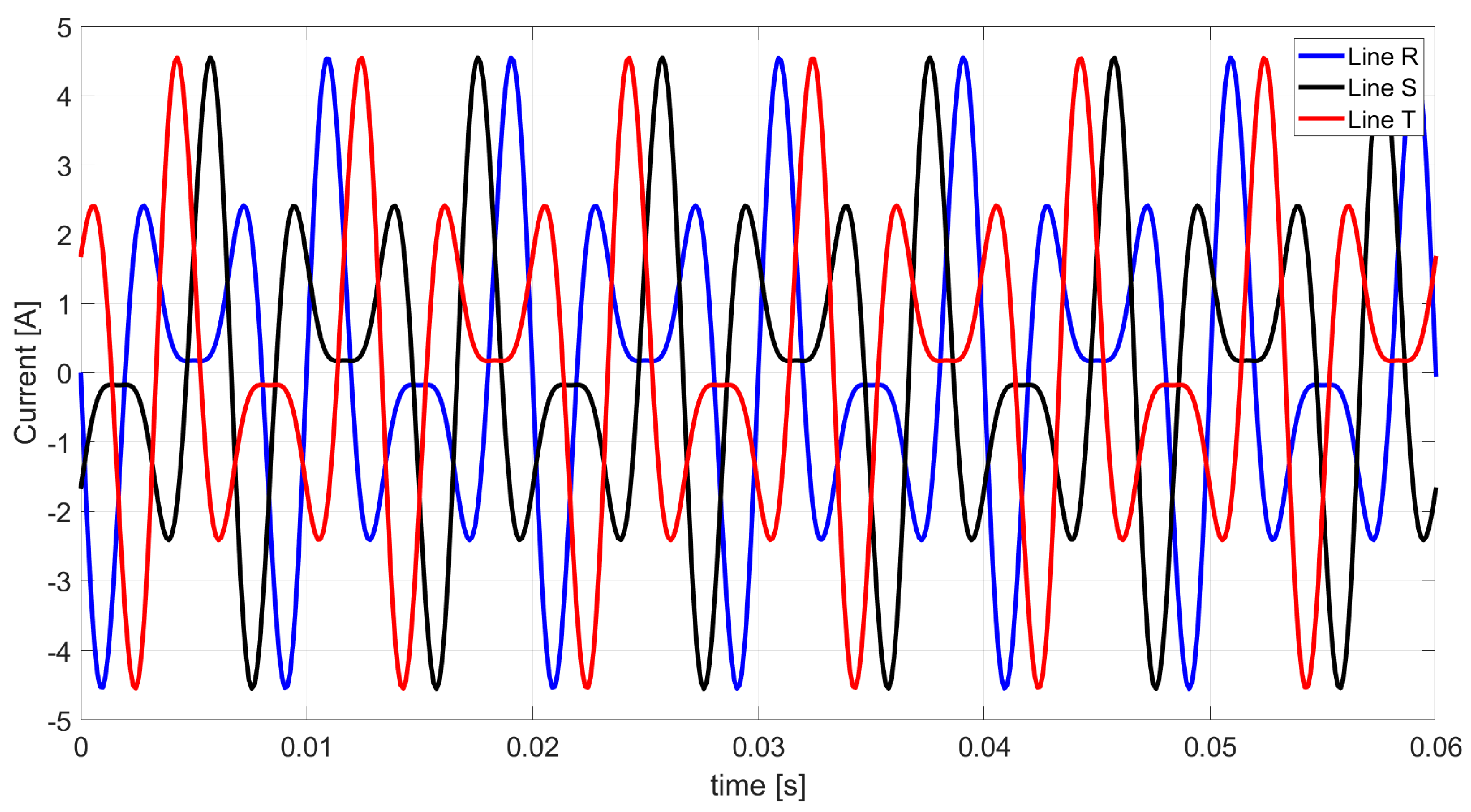
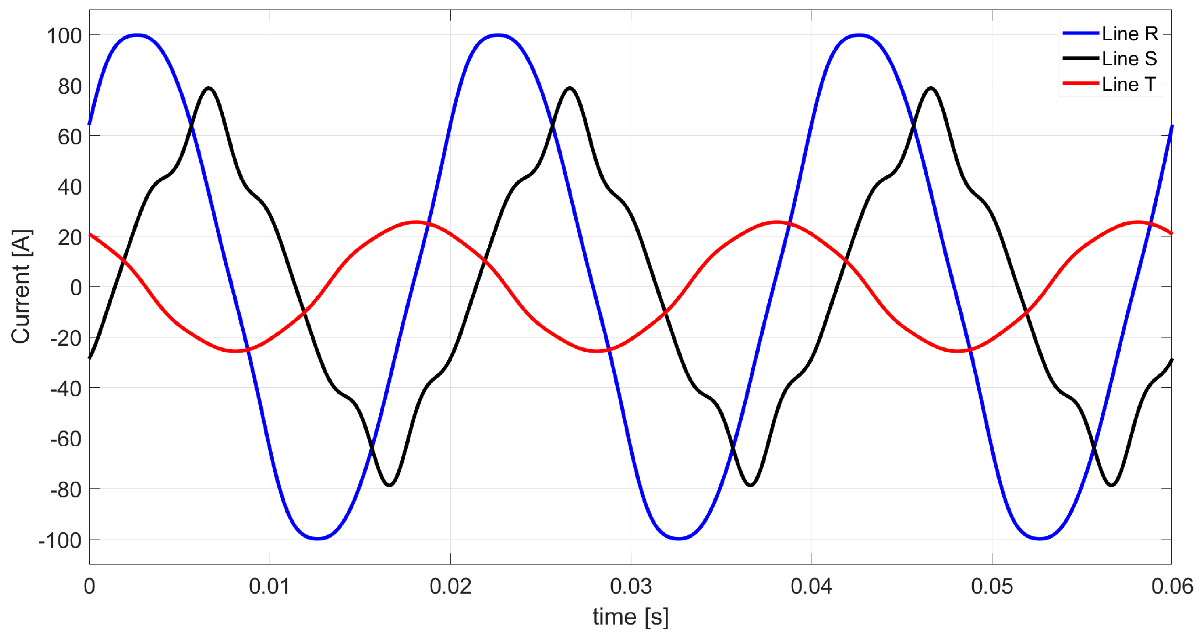
Figure 4 shows the waveform of line currents resulting from supplying a three-phase load with a nonsinusoidal symmetrical voltage.
The three-phase RMS value of the nonsinusoidal current of the load shown in Figure 4 is
i = 87.336     A
Table 4 presents the three-phase active powers (40) and reactive powers (41) of the individual harmonics and the powers of the entire system.
The apparent power (28), obtained by multiplying the three-phase RMS value of the supply voltage [2] by the three-phase RMS value of the load current (39), is
S = 35103.3   VA
The Budeanu distortion power (42) follows from the mathematical equation is
D B = 22587.5   VA
Based on expression (3), the equivalent conductance of the system in Figure 2 is
G e = 0.1321   S
Table 5 presents the equivalent parameters in the form of equivalent conductance and susceptance of the individual harmonics of a three-phase load.
Table 6 presents the unbalanced admittances and equivalent admittance values obtained from relations (15)–(18) described in CPC theory.
Based on relations (5), (7), (9), (21), (23), and (25), the three-phase RMS values of the currents’ components described by the CPC theory were calculated. The three-phase RMS values of the load currents’ components for the individual harmonics described by the CPC theory are presented in Table 7.
Table 8 shows the complex values of the currents’ components and the total current of a three-phase load for the individual harmonics following the CPC theory.
Based on Table 8 and relations (4), (6), (8), (20), (22), and (24), Figure 5, Figure 6, Figure 7, Figure 8, Figure 9 and Figure 10 show the waveforms of the individual load currents’ components described in the CPC theory.
In a system with an asymmetrical structure of a three-phase linear load, there is a current flow in the neutral line, the RMS value of which is associated with the three-phase RMS value of the unbalanced current of the zero sequence multiplied by the value of 3 , or use relation (37), and is equal to
i N = 96.022   A
Summing the values of the waveforms of the currents’ components shown in Figure 5, Figure 6, Figure 7, Figure 8, Figure 9 and Figure 10, we find the value of the waveform of the line currents based on the CPC theory. This waveform of line currents is presented in Figure 11.
As can be noted, the waveforms in Figure 4 and Figure 11 are similar.
According to the extended Budeanu theory and relation (45), the equivalent susceptance of the system from Figure 2 is
B e = 0.1011   S
Based on relations (5), (7), (21), (23), (25), (47), and (53), the three-phase RMS values of the currents’ components described in the extended Budeanu theory were calculated. The three-phase RMS values of the load currents’ components for the individual harmonics defined in the extended Budeanu theory are presented in Table 9.
Table 10 presents the complex values of the currents’ components and the total current of a three-phase load for the individual harmonics based on the extended Budeanu theory.
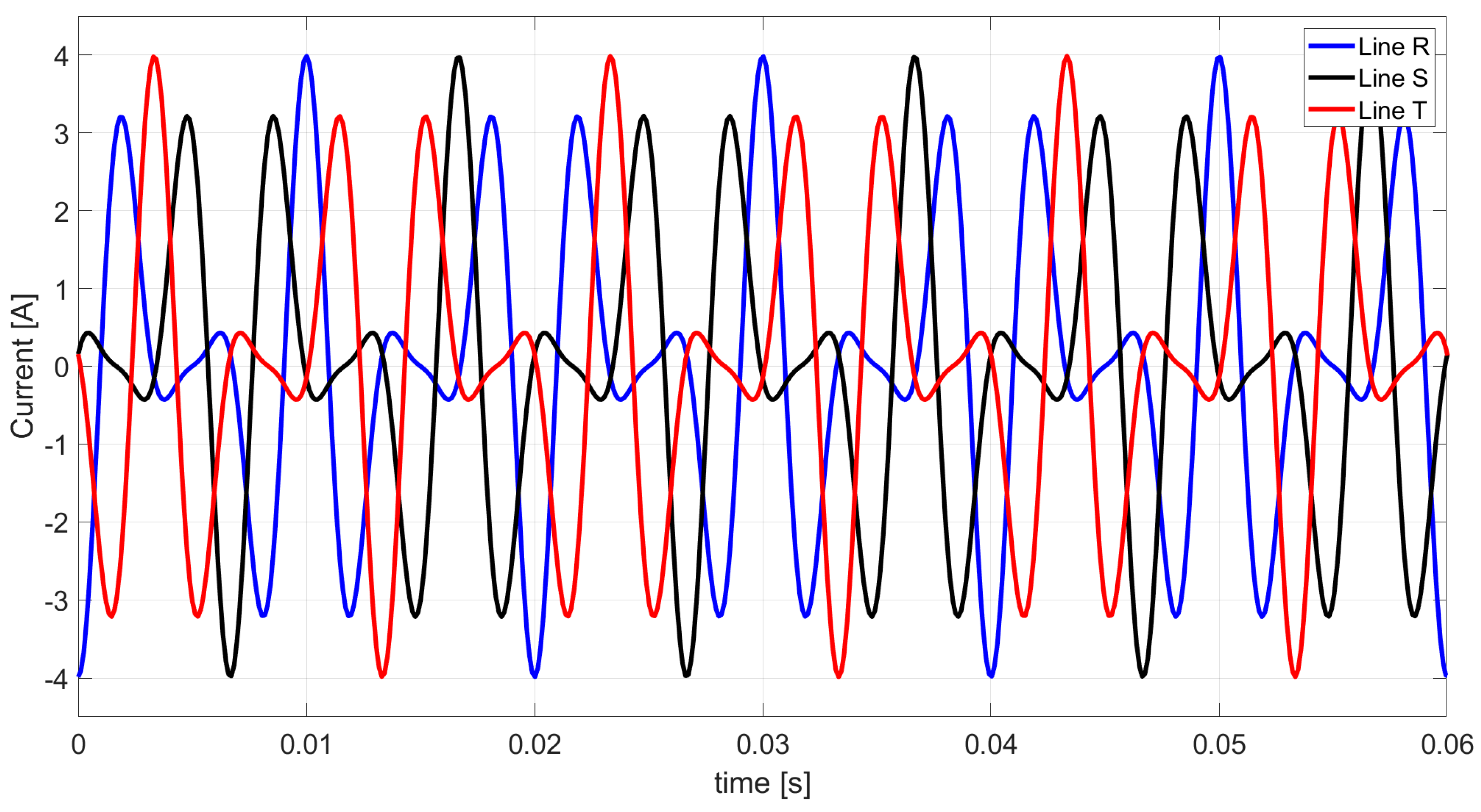
Based on Table 10 and relations (46) and (52), the waveforms of the two currents’ components of the three-phase load described by the extended Budeanu theory are shown in Figure 12 and 
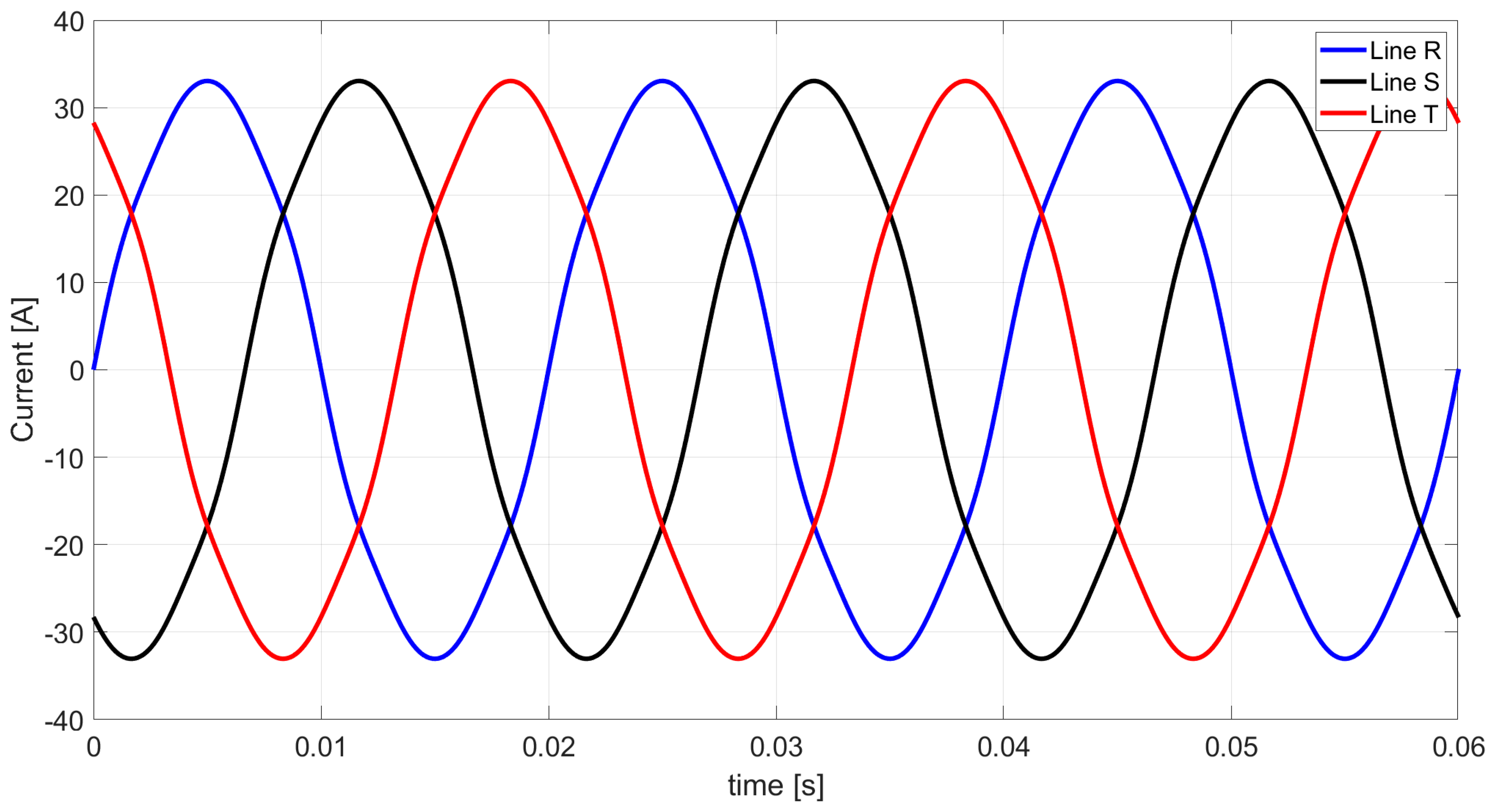
Figure 13. The waveforms of the active currents (Figure 5), the scattered currents (Figure 6), the three unbalanced currents of the positive sequence (Figure 7), the negative sequence (Figure 8) and the zero sequence (Figure 9) are equal in both approaches.
By summing the values of the currents’ components shown in Figure 5, Figure 6, Figure 8, Figure 9, Figure 10, Figure 12 and Figure 13, we obtain the value of the waveform of the line currents based on the extended Budeanu theory. This waveform of line currents is presented in Figure 14.
As can be seen, the waveforms in Figure 4, Figure 11 and Figure 14 are exactly the same.

8. Analysis and Discussion of the Obtained Results

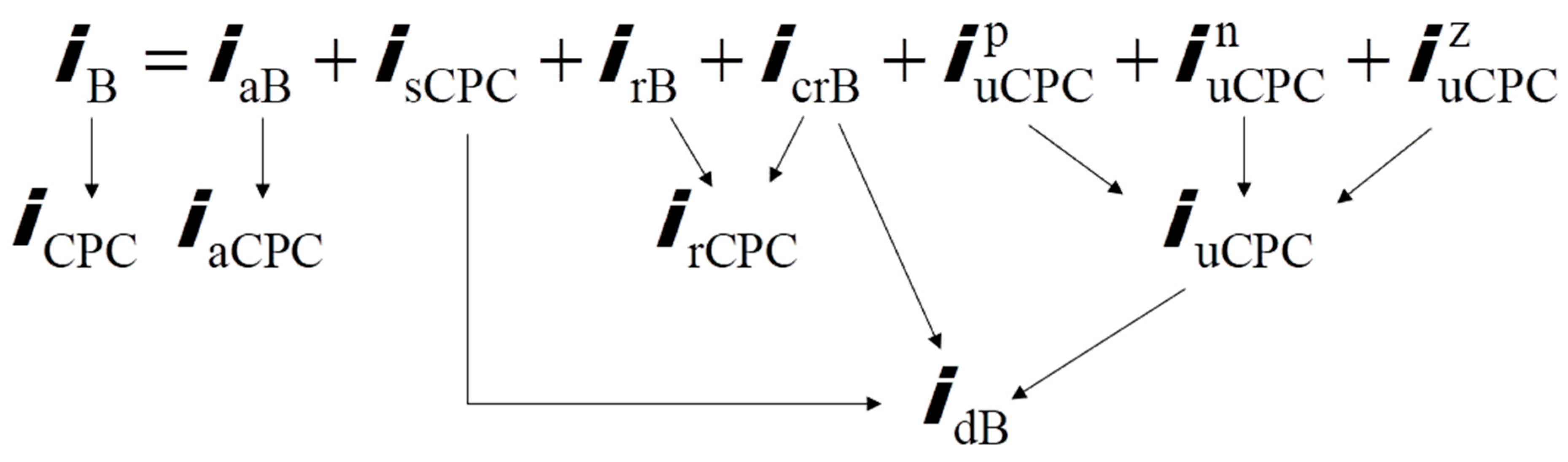
What remains to be solved are the components of the distortion current and thus the distortion power described by Budeanu. In three-phase four-wire systems supplied from a symmetrical nonsinusoidal voltage source and a three-phase asymmetrical load formed by resistance, inductance and capacitance in any configuration in each line, the distortion power defined by Budeanu is expressed by five components, namely: the scattered power, the Budeanu complemented reactive power and the three unbalanced powers of the positive, negative and zero sequence. Similarly, the five currents’ components relate to the Budeanu distortion current.
Figure 15 shows the conjunction of currents’ components in the extended Budeanu theory and the CPC theory. 
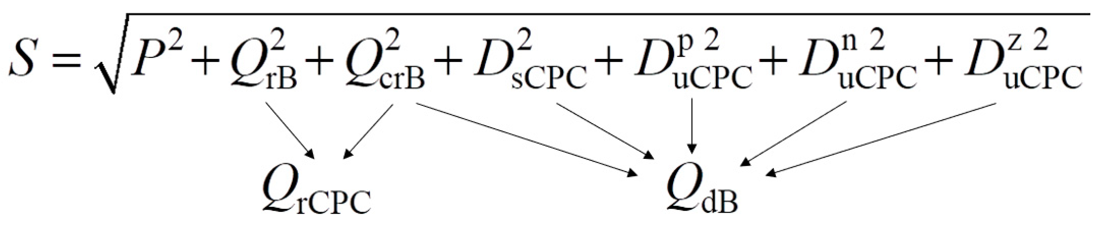
Figure 16, on the other hand, shows an identical conjunction of the components associated with the Budeanu distortion power.
Table 11 presents the complex values of the currents’ components and the Budeanu distortion current for the individual harmonics based on the extended Budeanu theory.
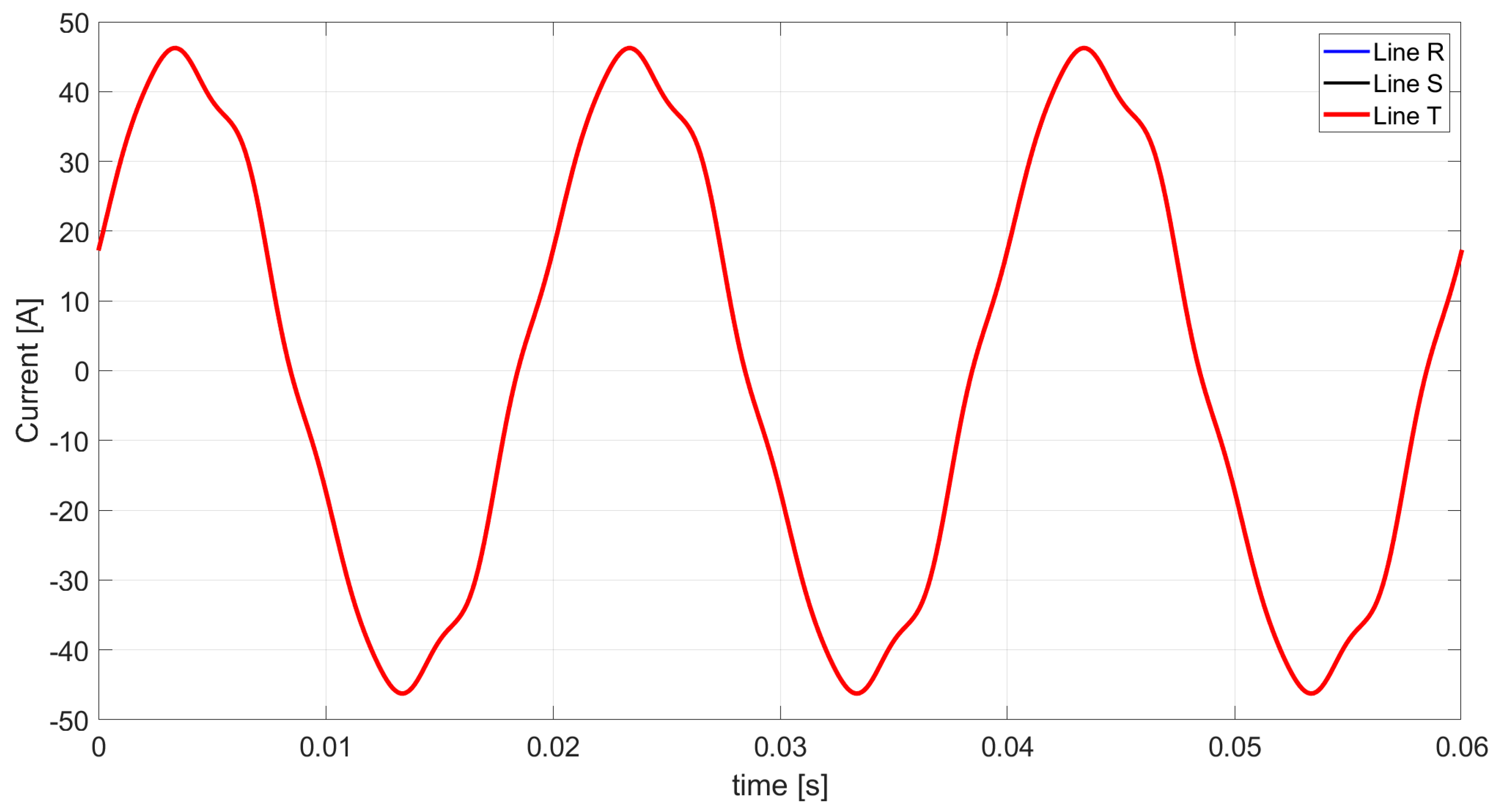
In accordance with the data in Table 11, the Budeanu distortion current waveform described by the extended Budeanu theory is shown in Figure 15.
In the analyzed example, the Budeanu distortion current, the waveform of which is shown in Figure 17, consists mainly of the zero sequence unbalanced current I z u . Hence, the typical 120° shift of the individual phases is not observed.
It should also be noted that the load in Figure 2, by suitably matching the imbalance in the elements in the individual lines, results in the Budeanu distortion power consisting of 5 components. At this point, it should be mentioned that the components of the Budeanu distortion power do not necessarily have to be five. It is possible to find situations in which the Budeanu distortion power consists of one, two, three or four powers’ components.
As presented in the theoretical illustration, the understanding of distortion current allows for its interpretation based on the number of components. If the distortion current has only one component, it indicates that the three-phase load is symmetrical, consisting solely of L or C elements (it is worth mentioning a case that is not necessarily unrealistic but deviates from theoretical assumptions, namely a load composed of resistive elements that change with the frequency of harmonics). When there are two components in the distortion current, the three-phase load is symmetrical and consists of RC or RL elements. The distortion current also has only two components when the load is composed of reactive elements in the form of an inductor L or a capacitor C, whose parameters do not change with the harmonic order (denying an increase or decrease in susceptance with an increase in frequency). In this case, specific harmonics occur, namely for harmonics with the positive sequence (n = 3k + 1), the two components of distortion current are the unbalanced currents of negative sequence and zero sequence. For harmonics with the negative sequence (n = 3k − 1), the two components of the distortion current are the unbalanced currents of positive sequence and zero sequence, and for harmonics with zero sequence (n = 3k), the two components are the unbalanced currents of positive sequence and negative sequence. A distortion current composed of three components exists when the three-phase load is asymmetrical and consists of reactive elements in the form of an inductor L or a capacitor C, with parameters unchanged with the harmonic order, and at least two distinct sequence harmonics. The scenario with three components in the distortion current also occurs when the three-phase load is asymmetrical and composed of R, L, or C elements, with only specific harmonics present. Specifically, for harmonics with the positive sequence (n = 3k + 1), the three components of distortion current are the unbalanced currents of negative sequence, zero sequence and the Budeanu complemented reactive current. For harmonics with the negative sequence (n = 3k − 1), the three components are the unbalanced currents of positive sequence, zero sequence and Budeanu complemented reactive current, and for harmonics with zero sequence (n = 3k), the three components are the unbalanced currents of positive sequence, negative sequence and Budeanu complemented reactive current. The case of four components in the distortion current occurs when the load is asymmetrical and consists of R, L, C, or variable R for at least two distinct sequence harmonics. The four components are also present when the three-phase load is asymmetrical and composed of RC or RL elements, with only specific harmonics occurring. Specifically, for harmonics with the positive sequence (n = 3k + 1), the four components of distortion current are the unbalanced currents of negative sequence, zero sequence, the Budeanu complemented reactive current and scattered current. For harmonics with the negative sequence (n = 3k − 1), the four components are the unbalanced currents of positive sequence zero sequence, Budeanu complemented reactive current and scattered current and for harmonics with zero sequence (n = 3k), the four components are the unbalanced currents of positive sequence, negative sequence, Budeanu complemented reactive current and scattered current.
As can be observed, Budeanu distortion current (distortion power) occurs when the load admittance varies with the harmonic order, i.e.,
Y n = Y h
where n and h denote the orders of harmonics in the set N = { 1 , 2 , 3 } . The assumption (80) can be presented in the form:
Y 1 = Y h N \ { 1 }
As observed from the analysis of specific cases describing distortion current components, this is possible due to the extension of Budeanu’s theory with the inclusion of Budeanu complemented reactive current described in this article for three-phase four-wire systems powered by a nonsinusoidal but symmetrical voltage source. Further development of the extended Budeanu theory should consider the possibility of constructing and synthesizing passive compensation systems and expanding the mathematical model for systems with asymmetrical power supply.

9. Conclusions

As presented in this paper, it is possible to develop Budeanu’s theory to a form in which the currents’ components of a three-phase four-wire load supplied from a symmetrical and nonsinusoidal voltage source can be defined. With the development of Budeanu’s theory, it is possible to accurately characterize the Budeanu distortion current by the components of the load current and not by the difference in complex RMS values (CRMS) vectors. This knowledge makes it possible to recognize the nature of the distortion power in the analyzed cases, which is not only related to the imbalance of the load but also to the variation of active or reactive powers.
The mathematical model in the extended Budeanu theory describing the equivalent parameters of a three-phase four-wire load is capable of distinguishing the orthogonal components of the current, and this makes it possible to determine the parameters of a passive compensator both with ideal parameters and a compensator minimizing reactive current and unbalanced current, which contributes to reducing the currents’ components associated with the reactance elements of the load (reactive powers and unbalanced powers).

Author Contributions

This paper was written by Z.S.; conceptualization, Z.S. and T.P.; methodology, Z.S. and T.P.; software, Z.S.; validation, Z.S. and T.P.; formal analysis, Z.S.; investigation, Z.S.; resources, Z.S. and T.P.; data curation, Z.S.; writing—original draft preparation, Z.S. and T.P.; writing—review and editing, Z.S. and T.P.; visualization, Z.S.; supervision, T.P.; project administration, Z.S.; funding acquisition, Z.S. All authors have read and agreed to the published version of the manuscript.

Funding

This work was supported by the Ministry of Science and Higher Education in Warsaw, Poland, at the Białystok University of Technology in Białystok, Poland, under research subsidies No. WZ/WE-IA/7/2023.

Institutional Review Board Statement

Not applicable.

Informed Consent Statement

Not applicable.

Data Availability Statement

Data is contained within the article.

Conflicts of Interest

The authors declare no conflicts of interest.

References

  1. Budeanu, C.I. Puissances Reactives et Fictives; Institut Romain de l’Energie: Bucharest, Romania, 1927. [Google Scholar]
  2. Czarnecki, L.S. Moce w Obwodach Elektrycznych z Niesinusoidalnymi Przebiegami Prądów i Napięć; Oficyna Wydawnicza Politechniki Warszawskiej: Warszawa, Poland, 2005. (In Polish) [Google Scholar]
  3. Torre, F.D.; Morando, A.P.; Sapienza, G. Power Quality Analysis of Electromechanical Energy Conversion: A Budeanu Approach. In Proceedings of the 14th International Conference on Harmonics and Quality of Power—ICHQP 2010, Bergamo, Italy, 26–29 September 2010; pp. 1–5. [Google Scholar]
  4. Jeltsema, D. Budeanu’s Concept of Reactive and Distortion Power Revisited. In Proceedings of the 2015 International School on Nonsinusoidal Currents and Compensation (ISNCC), Lagow, Poland, 15–18 June 2015; Volume 92, pp. 68–73. [Google Scholar]
  5. Willems, J.L. Budeanu’s reactive power and realted concepts revisited. IEEE Trans. Instrum. Meas. 2011, 60, 1182–1186. [Google Scholar] [CrossRef]
  6. Nowomiejski, Z. Generalized theory of electric power. Ar. Fur Elekt. 1981, 63, 177–182. [Google Scholar] [CrossRef]
  7. Zajkowski, K. Wady teorii mocy w obwodach jednofazowych według Budeanu i Fryzego. Autobusy Tech. Eksploat. Syst. Transp. 2016, 17, 1500–1504. (In Polish) [Google Scholar]
  8. Czarnecki, L.S. What is wrong with the Budeanu Concept of reactive and distortion power and why it should be abandoned. IEEE Trans. Instrum. Meas. 1987, IM-36, 834–837. [Google Scholar] [CrossRef]
  9. Czarnecki, L.S. Budeanu and Fryze: Two frameworks for interpreting power properties of circuits with nonsinusoidal voltages and currents. Electr. Eng. 1997, 80, 359–367. [Google Scholar] [CrossRef]
  10. Czarnecki, L.S. Considerations on the reactive power in nonsinusoidal situations. IEEE Trans. Instrum. Meas. 1985, IM-34, 399–404. [Google Scholar] [CrossRef]
  11. Sołjan, Z.; Zajkowski, M. Extension and correction of Budeanu power theory based on Currents’ Physical Components (CPC) theory for single-phase systems. Energies 2022, 15, 8321. [Google Scholar] [CrossRef]
  12. Sołjan, Z.; Zajkowski, M.; Borusiewicz, A. Reactive Power Compensation and Distortion Power Variation Identification in Extended Budeanu Power Theory for Single-Phase Systems. Energies 2024, 17, 227. [Google Scholar] [CrossRef]
  13. Czarnecki, L.S.; Toups, T.N. Working and reflected active powers of harmonics generating single-phase loads. In Proceedings of the International School on Nonsinusoidal Currents and Compensation 2013 (ISNCC 2013), Zielona Gora, Poland, 20–21 June 2013. [Google Scholar]
  14. Czarnecki, L.S. Currents’ Physical Components (CPC)—Based Power Theory. W review, Part I: Power properties of electrical Circuits and Systems. Przeg. Elektrotech. 2019, 95, 1–11. [Google Scholar] [CrossRef]
  15. Czarnecki, L.S. Currents’ Physical Components (CPC)—Based Power Theory. The review, Part II: Filters and reactive, switching and hybrid compensators. Przeg. Elektrotech. 2020, 96, 1–11. [Google Scholar]
  16. de Almeida Coelho, R.; Lima, É.M.; Brito, N.S.D. An Approach fo r Power Quantification Based on Stockwell Transform and CPC Power Theory. IEEE Trans. Instrum. Meas. 2022, 71, 1–10. [Google Scholar] [CrossRef]
  17. Czarnecki, L.S. Energy flow and power phenomena in electrical circuits illusions and reality. Electr. Eng. (Arch. Für Elektrotechnik) 1999, 82, 0119–0126. [Google Scholar] [CrossRef]
  18. Czarnecki, L.S.; Bhattarai, P. Power and compensation in circuits with distorted and asymmetrical current and voltage waveforms. Vol. 8, Power and compensation of circuits with asymmetrical supply voltage. Aut. Elektr. Zakł. 2015, 6, 8–18. (In Polish) [Google Scholar]
  19. Czarnecki, L.S.; Bhattarai, P.D. CPC-based reactive compensation of linear loads supplied with asymmetrical nonsinusoidal voltage. Przeg. Elektrotech. 2019, 1, 3–10. [Google Scholar]
  20. Czarnecki, L.S.; Almousa, M. Adaptive Balancing by Reactive Compensators of Three-Phase Linear Loads Supplied by Nonsinusoidal Voltage from Four-Wire Lines. Am. J. Electr. Power Energy Syst. 2021, 10, 32–42. [Google Scholar] [CrossRef]
  21. Czarnecki, L.S.; Haley, P.M. Power Properties of Four-Wire Systems at Nonsinusoidal Supply Voltage. IEEE Trans. Power Deliv. 2016, 31, 513–521. [Google Scholar] [CrossRef]
  22. Czarnecki, L.S.; Haley, P.M. Unbalanced Power in Four-Wire Systems and Its Reactive Compensation. IEEE Trans. Power Deliv. 2015, 30, 53–63. [Google Scholar] [CrossRef]
  23. Zajkowski, K.; Woźniak, M. Description of a three-phase, four-wire systems with a nonlinear receiver and an asymmetric voltage source using CPC power theory. J. Automotion Electron. Electr. Eng. 2024, 5, 47–66. [Google Scholar] [CrossRef]
  24. Sołjan, Z.; Hołdyński, G.; Zajkowski, M. CPC-Based Minimizing of Balancing Compensators in Four-Wire Nonsinusoidal Asymmetrical Systems. Energies 2021, 14, 1815. [Google Scholar] [CrossRef]
  25. Sołjan, Z.; Hołdyński, G.; Zajkowski, M. CPC-based current′s description in three-phase four-wire systems with asymmetrical and nonsinusoidal waveforms. Bull. Pol. Acad. Sci. Tech. Sci. 2020, 68, 1127–1134. [Google Scholar] [CrossRef]
  26. Holdynski, G.; Soljan, Z.; Zajkowski, M. CPC-based reactive compensation at three-phase four-wire systems powered from asymmetric sinusoidal voltage source. In Proceedings of the 2019 20th International Scientific Conference on Electric Power Engineering (EPE), Kouty nad Desnou, Czech Republic, 15–17 May 2019; Institute of Electrical and Electronics Engineers (IEEE): Picataway, NJ, USA, 2019; pp. 1–6. [Google Scholar]
  27. Soljan, Z.; Holdynski, G.; Zajkowski, M. Decomposition of the load′s current supplied from a sinusoidal and asymmetrical voltage source in accordance with the Currents’ Physical Components (CPC) Theory. In Proceedings of the 2019 20th International Scientific Conference on Electric Power Engineering (EPE), Kouty nad Desnou, Czech Republic, 15–17 May 2019; Institute of Electrical and Electronics Engineers (IEEE): Picataway, NJ, USA, 2019; pp. 1–6. [Google Scholar]
  28. Zajkowski, K. Reactive power compensation in a three-phase power supply system in an electric vehicle charging station. J. Mech. Energy Eng. 2018, 2, 75–84. [Google Scholar] [CrossRef]
  29. Zajkowski, K.; Duer, S.; Paś, J.; Pokorádi, L. Cooperation of a Non-Linear Receiver with a Three-Phase Power Grid. Energies 2023, 16, 1418. [Google Scholar] [CrossRef]
  30. Coelho, R.D.A.; Brito, N.S.D.; de Lira, G.R.S.; Lima, É.M. Effects of currents decomposition on power calculation in nonsinusoidal conditions. Electr. Eng. 2020, 102, 2325–2339. [Google Scholar] [CrossRef]
  31. Czarnecki, L.S. Minimisation of distortion power of nonsinusoidal source applied to linear loads. IEE Proc. C (Gener. Transm. Distrib.) 1981, 128, 208–210. [Google Scholar] [CrossRef]
  32. Czarnecki, L.S. Minimisation of unbalanced and reactive currents in three-phase asymmetrical circuits with nonsinusoidal voltage. IEE Proc. B (Electr. Power Appl.) 1992, 139, 347–354. [Google Scholar] [CrossRef]
  33. Czarnecki, L.S. Minimization of reactive power under nonsinusoidal conditions. IEEE Trans. Instrum. Meas. 1987, 36, 18–22. [Google Scholar] [CrossRef]
  34. Zajkowski, K.; Duer, S. Decomposition of the Voltages in a Three-Phase Asymmetrical Circuit with a Non-Sinusoidal Voltage Source. Energies 2023, 16, 7616. [Google Scholar] [CrossRef]
  35. Popescu, M.; Bitoleanu, A.; Suru, V. Currents’ physical components theory implementation in shunt active power filtering for unbalanced loads. In Proceedings of the International School on Nonsinusoidal Currents and Compensation (ISNCC), Zielona Góra, Poland, 20–21 June 2013. [Google Scholar]
  36. Grasso, F.; Luchetta, A.; Manetti, S.; Piccirilli, M.C.; Reatti, A.; Somma, M.; Cenghialta, F.; D’Antuono, E. Improvement of Power Flow Analysis based on Currents’ Physical Component (CPC) Theory, Circuits and Systems (ISCAS). In Proceedings of the IEEE International Symposium on Circuits and Systems (ISCAS), Florence, Italy, 27–30 May 2018; pp. 1–5. [Google Scholar]
  37. Patrascu, A.; Popescu, M. Comparative active current calculation by p-q and CPC Theories. Ann. Univ. Craiova 2011, 35, 25–30. [Google Scholar]
  38. Bitoleanu, A.; Popescu, M.; Dobriceanu, M.; Nastasoiu, F. Current decomposition methods on p-q and CPC Theories for active filtering reasons. WSEAS Trans. Circ. Syst. 2008, 7, 869–878. [Google Scholar]
  39. Vahle, D.; Staudt, V. Comparison and extension of advanced frequency domain non-active power decompositions. Electr. Power Syst. Res. 2023, 221, 109448. [Google Scholar] [CrossRef]
  40. Popławski, T.; Kurkowski, M. Nonlinear Loads in Lighting Installations—Problems and Threats. Energies 2023, 16, 6024. [Google Scholar] [CrossRef]
  41. Popławski, T.; Kurkowski, M.; Mirowski, J. Improving the Quality of Electricity in Installations with Mixed Lighting Fittings. Energies 2020, 13, 6017. [Google Scholar] [CrossRef]
  42. Davidovic, M.; Djordjevic, N.; Mikulovic, J.; Kostic, M.; Radakovic, Z. Voltage distortion in LED street lighting installations. Electr. Eng. 2021, 103, 2161–2180. [Google Scholar] [CrossRef]
  43. Bellia, L.; Błaszczak, U.; Fragliasso, F.; Gryko, L. Matching CIE illuminants to measured spectral power distributions: A method to evaluate non-visual potential of daylight in two European cities. Sol. Energy 2020, 208, 830–858. [Google Scholar] [CrossRef]
  44. Hołdyński, G.; Skibko, Z.; Firlit, A.; Walendziuk, W. Analysis of the Impact of a Photovoltaic Farm on Selected Parameters of Power Quality in a Medium-Voltage Power Grid. Energies 2024, 17, 623. [Google Scholar] [CrossRef]
  45. Hołdyński, G.; Skibko, Z.; Borusiewicz, A. Analysis of the Influence of Load on the Value of Zero-Voltage Asymmetry in Medium-Voltage Networks Operating with Renewable Energy Sources. Energies 2023, 16, 580. [Google Scholar] [CrossRef]
  46. Skibko, Z.; Hołdyński, G.; Borusiewicz, A. Impact of Wind Power Plant Operation on Voltage Quality Parameters—Example from Poland. Energies 2022, 15, 5573. [Google Scholar] [CrossRef]
  47. Jayaraman, M. Passive filter topologies for grid connected and standalone PV systems: A survey. ECS Trans. 2022, 107, 12083–12095. [Google Scholar] [CrossRef]
  48. Argüello, A.; Torquato, R.; Freitas, W. Passive filter tunning for harmonic resonance mitigation in Wind Park. IEEE Trans. Power Deliv. 2023, 38, 3834–3846. [Google Scholar] [CrossRef]
  49. Stankiewicz, J.M. Estimation of the Influence of the Coil Resistance on the Power and Efficiency of the WPT System. Energies 2023, 16, 6210. [Google Scholar] [CrossRef]
  50. Choroszucho, A. Analysis of the influence of electrical parameters of concrete and reinforcement inside concrete walls on the values of the electric field intensity. Przeg. Elektrotech. 2022, 98, 111–117. [Google Scholar] [CrossRef]
  51. Hui, S.Y.R. Wireless Power Transfer: A brief review & update. In Proceedings of the 2013 5th International Conference on Power Electronics Systems and Applications(PESA), Hong Kong, China, 11–13 December 2013; pp. 1–4. [Google Scholar]
  52. Lee, C.H.; Jung, G.; Al Hosani, K.; Song, B.; Seo, D.-K.; Cho, D. Wireless Power Transfer system for an autonomous electric vehicle. In Proceedings of the 2020 IEEE Wireless Power Transfer Conference (WPTC), Seoul, Republic of Korea, 15–19 November 2020; pp. 467–470. [Google Scholar]
  53. Zhang, Z.; Pang, H.; Georgiadis, A.; Cecati, C. Wireless Power Transfer—An overview. IEEE Trans. Ind. Electron. 2018, 66, 1044–1058. [Google Scholar] [CrossRef]
  54. Buchholz, F. Das Begriffsystem Rechtleistung, Wirkleistung, Totale Blindleistung; Selbstverlag: Munchen, Germany, 1950. [Google Scholar]
Figure 1. Unbalanced linear load supplied with nonsinusoidal symmetrical voltage.
Energies 17 01043 g001
Figure 2. Scheme of a three-phase four-wire system supplied with a nonsinusoidal symmetrical voltage with an asymmetrical linear load.
Energies 17 01043 g002
Figure 3. The waveform of nonsinusoidal voltage values at the terminals of a three-phase linear load.
Energies 17 01043 g003
Figure 4. Waveform of the line currents obtained from Ohm’s law and Kirchhoff’s law.
Energies 17 01043 g004
Figure 5. The waveform of active currents based on the CPC theory.
Energies 17 01043 g005
Figure 6. The waveform of scattered currents based on the CPC theory.
Energies 17 01043 g006
Figure 7. The waveform of reactive currents based on the CPC theory.
Energies 17 01043 g007
Figure 8. The waveform of unbalanced currents of the positive sequence based on the CPC theory.
Energies 17 01043 g008
Figure 9. The waveform of unbalanced currents of the negative sequence based on the CPC theory.
Energies 17 01043 g009
Figure 10. The waveform of unbalanced currents of the zero sequence based on the CPC theory.
Energies 17 01043 g010
Figure 11. The waveform of the line currents based on the CPC theory.
Energies 17 01043 g011
Figure 12. The waveform of the Budeanu reactive currents based on the extended Budeanu theory.
Energies 17 01043 g012
Figure 13. The waveform of the Budeanu complemented reactive currents based on the extended Budeanu theory.
Energies 17 01043 g013
Figure 14. The waveform of the line currents based on the extended Budeanu theory.
Energies 17 01043 g014
Figure 15. Connection of the 3-p 4-w currents’ components of the load in the extended Budeanu and the CPC theories.
Energies 17 01043 g015
Figure 16. Connection of the 3-p 4-w powers’ components of the load in the extended Budeanu and the CPC theories.
Energies 17 01043 g016
Figure 17. The waveform of the Budeanu distortion currents based on the extended Budeanu theory.
Energies 17 01043 g017
Table 1. List of resistance, inductive reactance and capacitive reactance values for the fundamental harmonic.
Parameter in Ω Line RLine SLine T
Resistance 251
Inductive reactance3.142-12.566
Capacitive reactance0.6370.398-
Table 2. List of complex admittance values for individual harmonics.
Harmonic OrderLine R in [S]Line S in [S]Line T in [S]
n = 1 0.312 e j 51.4 0.199 e j 4.6 0.079 e j 85.5
n = 3 0.106 e j 77.8 0.200 e j 1.5 0.027 e j 88.5
n = 5 0.064 e j 82.7 0.200 e j 0.9 0.016 e j 89.1
n = 7 0.046 e j 84.8 0.200 e j 0.7 0.011 e j 89.4
Table 3. List of complex line currents values for individual harmonics.
Harmonic OrderLine R in [A]Line S in [A]Line T in [A]
n = 1 71.75 e j 51.4 45.86 e j 115.5 18.25 e j 34.6
n = 3 1.59 e j 77.8 3.00 e j 1.5 0.40 e j 88.5
n = 5 1.59 e j 82.7 5.00 e j 120.9 0.40 e j 150.9
n = 7 0.46 e j 84.8 2.00 e j 119.4 0.11 e j 30.7
Table 4. List of three-phase active and reactive powers values of individual harmonics and the total three-phase active and reactive powers of the entire system.
Harmonic OrderActive Power P in [W]Reactive Power Q in [var]
n = 121,143.316,243.3
n = 350.228.1
n = 5130.247.4
n = 720.45.4
SUM21,344.116,324.2
Table 5. List of conductance and susceptance values of individual harmonics.
Harmonic OrderConductance in [S]Susceptance in [S]
n = 1 0.1332 e j 0 0.1024 e j 90
n = 3 0.0744 e j 0 0.0416 e j 90
n = 5 0.0694 e j 0 0.0253 e j 90
n = 7 0.0681 e j 0 0.0181 e j 90
Table 6. List of unbalanced admittances and equivalent admittance values in CPC theory.
Harmonic
Order
Unbalanced AdmittanceEquivalent Admittance
Y u p Y u n Y u z Y
n = 1 0.000 e j 0 0.016 e j 77.7 0.139 e j 65.3 0.168 e j 37.5
n = 3 0.044 e j 143 0.090 e j 100.7 0.000 e j 0 0.085 e j 29.2
n = 5 0.081 e j 108.2 0.000 e j 0 0.053 e j 133.1 0.074 e j 20
n = 7 0.000 e j 0 0.057 e j 129.2 0.077 e j 111.5 0.071 e j 14.9
Table 7. List of three-phase RMS values of currents’ components for individual harmonics described by the CPC theory.
Harmonic
Order
i a i s i r i u p i u n i u z
n = 152.6330.44140.77406.18555.375
n = 33.4331.5011.0811.1422.3400
n = 55.7212.7141.0953.49002.295
n = 72.2881.1090.31400.9851.327
RMS53.1043.32340.8053.6726.68655.438
Table 8. List of values of complex currents’ components and total current for individual harmonics based on the CPC theory.
Current [A]LineHarmonic Order
n = 1n = 3n = 5n = 7
I a R 30.39 e j 0 1.98 e j 0 3.30 e j 0 1.32 e j 0
S 30.39 e j 120 1.98 e j 0 3.30 e j 120 1.32 e j 120
T 30.39 e j 120 1.98 e j 0 3.30 e j 120 1.32 e j 120
I s R 0.26 e j 0 0.87 e j 180 1.57 e j 180 0.64 e j 180
S 0.26 e j 120 0.87 e j 180 1.57 e j 60 0.64 e j 60
T 0.26 e j 120 0.87 e j 180 1.57 e j 60 0.64 e j 60
I r R 23.54 e j 90 0.62 e j 90 0.63 e j 90 0.18 e j 90
S 23.54 e j 150 0.62 e j 90 0.63 e j 30 0.18 e j 150
T 23.54 e j 30 0.62 e j 90 0.63 e j 150 0.18 e j 30
I p u R 0.00 e j 0 0.66 e j 143 2.02 e j 108.2 0.00 e j 0
S 0.00 e j 0 0.66 e j 23 2.02 e j 131.8 0.00 e j 0
T 0.00 e j 0 0.66 e j 97 2.02 e j 11.8 0.00 e j 0
I n u R 3.57 e j 77.7 1.35 e j 100.7 0.00 e j 0 0.57 e j 129.1
S 3.57 e j 42.3 1.35 e j 19.3 0.00 e j 0 0.57 e j 110.9
T 3.57 e j 162.3 1.35 e j 139.3 0.00 e j 0 0.57 e j 9.1
I z u R 31.97 e j 65.3 0.00 e j 0 1.33 e j 133.1 0.77 e j 111.5
S 31.97 e j 65.3 0.00 e j 0 1.33 e j 133.1 0.77 e j 111.5
T 31.97 e j 65.3 0.00 e j 0 1.33 e j 133.1 0.77 e j 111.5
I R 71.75 e j 51.4 1.59 e j 77.8 1.59 e j 82.7 0.46 e j 84.8
S 45.86 e j 115.5 3.00 e j 1.5 5.00 e j 120.9 2.00 e j 119.4
T 18.25 e j 34.6 0.40 e j 88.5 0.40 e j 150.9 0.11 e j 30.7
Table 9. List of three-phase RMS values of the currents’ components for the individual harmonics described by the extended Budeanu theory.
Harmonic
Order
i a i s i rB i crB i u p i u n i u z
n = 152.6330.44140.2550.52006.18555.375
n = 33.4331.5012.6251.5441.1422.3400
n = 55.7212.7144.3763.2803.49002.295
n = 72.2881.1091.7501.43600.9851.327
RMS53.1043.32340.6143.9343.6726.68655.438
Table 10. List of values of complex currents’ components and total current for individual harmonics based on the extended Budeanu theory.
Current [A]LineHarmonic Order
n = 1n = 3n = 5n = 7
I a R 30.39 e j 0 1.98 e j 0 3.30 e j 0 1.32 e j 0
S 30.39 e j 120 1.98 e j 0 3.30 e j 120 1.32 e j 120
T 30.39 e j 120 1.98 e j 0 3.30 e j 120 1.32 e j 120
I s R 0.26 e j 0 0.87 e j 180 1.57 e j 180 0.64 e j 180
S 0.26 e j 120 0.87 e j 180 1.57 e j 60 0.64 e j 60
T 0.26 e j 120 0.87 e j 180 1.57 e j 60 0.64 e j 60
I rB R 23.24 e j 90 1.52 e j 90 2.53 e j 90 1.01 e j 90
S 23.24 e j 150 1.52 e j 90 2.53 e j 30 1.01 e j 150
T 23.24 e j 30 1.52 e j 90 2.53 e j 150 1.01 e j 30
I crB R 0.30 e j 90 0.89 e j 90 1.89 e j 90 0.83 e j 90
S 0.30 e j 150 0.89 e j 90 1.89 e j 150 0.83 e j 30
T 0.30 e j 30 0.89 e j 90 1.89 e j 30 0.83 e j 150
I p u R 0.00 e j 0 0.66 e j 143 2.02 e j 108.2 0.00 e j 0
S 0.00 e j 0 0.66 e j 23 2.02 e j 131.8 0.00 e j 0
T 0.00 e j 0 0.66 e j 97 2.02 e j 11.8 0.00 e j 0
I n u R 3.57 e j 77.7 1.35 e j 100.7 0.00 e j 0 0.57 e j 129.1
S 3.57 e j 42.3 1.35 e j 19.3 0.00 e j 0 0.57 e j 110.9
T 3.57 e j 162.3 1.35 e j 139.3 0.00 e j 0 0.57 e j 9.1
I z u R 31.97 e j 65.3 0.00 e j 0 1.33 e j 133.1 0.77 e j 111.5
S 31.97 e j 65.3 0.00 e j 0 1.33 e j 133.1 0.77 e j 111.5
T 31.97 e j 65.3 0.00 e j 0 1.33 e j 133.1 0.77 e j 111.5
I R 71.75 e j 51.4 1.59 e j 77.8 1.59 e j 82.7 0.46 e j 84.8
S 45.86 e j 115.5 3.00 e j 1.5 5.00 e j 120.9 2.00 e j 119.4
T 18.25 e j 34.6 0.40 e j 88.5 0.40 e j 150.9 0.11 e j 30.7
Table 11. List of complex values of currents’ components and distortion current for individual harmonics based on the extended Budeanu theory.
Current [A]LineHarmonic Order
n = 1n = 3n = 5n = 7
I s R 0.26 e j 0 0.87 e j 180 1.57 e j 180 0.64 e j 180
S 0.26 e j 120 0.87 e j 180 1.57 e j 60 0.64 e j 60
T 0.26 e j 120 0.87 e j 180 1.57 e j 60 0.64 e j 60
I crB R 0.30 e j 90 0.89 e j 90 1.89 e j 90 0.83 e j 90
S 0.30 e j 150 0.89 e j 90 1.89 e j 150 0.83 e j 30
T 0.30 e j 30 0.89 e j 90 1.89 e j 30 0.83 e j 150
I p u R 0.00 e j 0 0.66 e j 143 2.02 e j 108.2 0.00 e j 0
S 0.00 e j 0 0.66 e j 23 2.02 e j 131.8 0.00 e j 0
T 0.00 e j 0 0.66 e j 97 2.02 e j 11.8 0.00 e j 0
I n u R 3.57 e j 77.7 1.35 e j 100.7 0.00 e j 0 0.57 e j 129.1
S 3.57 e j 42.3 1.35 e j 19.3 0.00 e j 0 0.57 e j 110.9
T 3.57 e j 162.3 1.35 e j 139.3 0.00 e j 0 0.57 e j 9.1
I z u R 31.97 e j 65.3 0.00 e j 0 1.33 e j 133.1 0.77 e j 111.5
S 31.97 e j 65.3 0.00 e j 0 1.33 e j 133.1 0.77 e j 111.5
T 31.97 e j 65.3 0.00 e j 0 1.33 e j 133.1 0.77 e j 111.5
I dB R 35.84 e j 66.3 1.65 e j 178.6 3.24 e j 163 1.40 e j 156.5
S 30.94 e j 59.7 1.89 e j 57.5 3.11 e j 176.9 1.24 e j 63.3
T 29.38 e j 69.9 2.27 e j 150.4 3.92 e j 27.1 1.60 e j 94.2
Disclaimer/Publisher’s Note: The statements, opinions and data contained in all publications are solely those of the individual author(s) and contributor(s) and not of MDPI and/or the editor(s). MDPI and/or the editor(s) disclaim responsibility for any injury to people or property resulting from any ideas, methods, instructions or products referred to in the content.

