Abstract
This article presents methods of reactive power compensation using passive elements in the form of a capacitor (C) or choke (L) and an LC structure selected in such a way as to lead to the minimization of the reactive current (reactive power) of a single-phase system. The adaptation of the parameters of a passive compensator, reducing reactive power and/or distortion power, was possible through the extended Budeanu theory. In addition, through the extended Budeanu theory and also through the knowledge of the equivalent parameters of the linear load, the obtained results of the increase in distortion power, depending on the structure of the passive compensator, were analyzed. The values listed in the tables, as well as the waveforms of the component currents of a single-phase linear load, were obtained based on calculations and simulation models in MATLAB/Simulink software R2023a.
1. Introduction
The concept of “Distortion Power” has been known in electrical engineering since 1927 [1,2,3,4]. The author of this formulation was C.I. Budeanu [1]. According to Budeanu’s basic theory, there can be three powers in a system with nonsinusoidal waveforms, i.e., active power, reactive power, and the aforementioned distortion power. Over the years, countless scientists from all over the world have tried to explain why there is an increase in distortion power after connecting the optimal capacity to compensate for reactive power [5,6,7,8,9,10]. For nearly 100 years, since the Budeanu theory was developed, no one has been able to relate the parameters of the load to the distortion power [11], and, for the same number of years, no one has been able to explain why compensating for reactive power with a capacitor leads to an amplification in the value of distortion power [2,7,8,9,10]. It was only through the work of the authors of [11] and using the Currents’ Physical Components (CPC) theory by Czarnecki [2,4,5,6] that it was possible to determine the component powers involved in Budeanu’s distortion power. As there was no correlation between the distortion power and the equivalent parameters of the load in earlier work, it was also impossible to build an effective passive compensator. It was also impossible to find the optimal capacity [7,8,9,10], or, once the optimal capacity was chosen, the problem of increasing waveform distortion could not be interpreted, despite the fragmentary reactive power compensation described by Budeanu.
The approach to passive compensator design has declined in recent years. However, in the 1980s and 1990s, it was completely different. It was during these two decades that most works referring to compensators/filters/passive systems were produced [12,13,14,15,16,17,18]. Depending on the approach and energy description, it was attempted to find the optimal capacity or inductance [12,19,20] and build an LC compensator system with series and parallel connected elements [2,6,21,22] so that specific current harmonics caused by the nonsinusoidal voltage waveform could be compensated. These decades also saw the development of a method based on minimizing reactive current rather than fully compensating for it [2,6,21,22,23,24,25]. To date, passive compensators are used in conjunction with power electronic filters (known as active power filters), forming hybrid systems [13,15,22,26,27]. In principle, the approach to hybrid systems is relatively basic, as it involves fitting capacitors or chokes for a chosen amount of reactive power and then adding a power electronics system to compensate for the remaining reactive power, which is a significantly lower value [26,27,28,29,30].
This might seem to be abandoning the use of passive compensators. However, due to economic aspects, they are still extensively used in various areas. The first such sector in which passive compensators have been used for many years almost without interruption is street lighting [31,32,33,34,35]. Although there has been a rapid expansion in the use of LED lighting worldwide [36,37], passive systems are still being implemented. Only the design of the compensator has changed, as, previously, capacitors were used for compensation, while now, due to the capacitive nature of reactive power generated by electronic systems, chokes are installed [35,36]. The second area of the use of reactance compensators is in the broadly considered industry [38,39,40,41]. The industrial community uses passive systems because of their potential for power factor buffering [38,39,41]. In this area, passive systems very often differ from each other, mainly in terms of how chokes or capacitors are connected. In systems where reactive power does not frequently change over a short period, typical control via contactors is most often used. Where higher responsiveness of the compensator system is needed, power electronic components are used for control, e.g., transistors or thyristors. Another area where passive compensators are applied is Renewable Energy Sources [14,42,43,44,45]. Compensators, or LC filters, are used when correcting the supply conditions of heat pumps. Recent studies realized by the authors of this publication show that reactance compensators together with a voltage regulator should also be adopted for photovoltaic installations. The reason is the increase in voltage at the point of connection of such a PV installation [44,45]. The last area where cost-effective passive systems should be used to compensate for reactive power or improve power conditions is the sector of wireless power transmission (WPT) [46,47,48,49,50,51]. Such systems are characterized by the use of coils for energy transfer and are primarily based on the power supply system that is locally available. A specific type of passive compensators are interference filters, which can be found in a great many devices [52,53,54].
The article is divided into eight Sections. Section 1 presents a description of Budeanu’s power theory and a literature review related to the design of passive compensators and reactance elements selected for hybrid systems. An area where those systems can be used has also been added to the literature review. The Section 2 is a short description of the extended Budeanu theory with the current components of a single-phase linear load powered from a nonsinusoidal voltage source. Section 3 describes the process of designing passive compensators in the form of the optimal capacity or optimal inductance. This section presents the relationships and assumptions that should be satisfied to compensate for the Budeanu reactive current. The Section 4 is theoretical illustration 1, which shows the calculation of the original system. Thus, the equivalent parameters of the load and the values of the component currents before compensation were obtained. The rest of Section 4 presents the value of the capacitor with the optimal capacity and also the necessary calculations that resulted in a change in the values of the various equivalent parameters and the component currents of the load. Section 5 describes further reactance compensator structures designed based on the Currents’ Physical Components (CPC) theory. The section includes information on LC- or L-compensator structures and the relationships through which the optimal values for capacitor capacity and choke inductance are accomplished. The Section 6 is theoretical illustration 2, in which an LC compensator is added to the original system. This section presents the calculated equivalent parameters and component currents of a single-phase load after compensation with an LC compensator. The Section 7 presents an analysis of the results obtained from different compensator structures. The phenomenon of an increase in the distortion of the current waveform of the load due to the use of a capacitor with an optimally chosen capacity was also analyzed, which has been described quite widely in the literature. The final Section 8 presents conclusions based on the literature review, the obtained calculated values, and the performed analysis.
2. Currents’ Components in Extended Budeanu Theory
The extended Budeanu theory is described in [11]. The basis that made it possible to develop the Budeanu approach is the Currents’ Physical Components (CPC) theory made by Czarnecki [2,4,5,6]. Both approaches are based on the identification of equivalent single-phase load parameters. It is, therefore, possible to identify the component currents of the load and relate them to physical phenomena by means of specific equivalent parameters. The individual component currents, together with the voltage, form the powers of a single-phase linear load, following the extended Budeanu theory.
A load, connected in a single-phase system (Figure 1), can be powered by the nonsinusoidal voltage source, whose waveform can be described as
where is the complex RMS (CRMS) value of the voltage harmonic, and is the harmonic order.
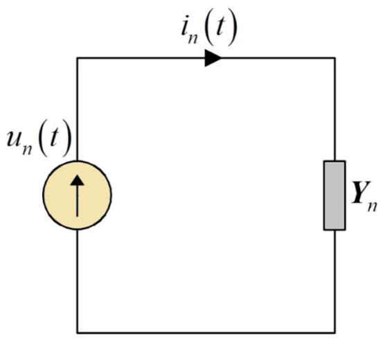
Figure 1.
Single-phase circuit powered by a nonsinusoidal voltage waveform.
The result of applying voltage (1) to the terminals of the time-invariant linear load (LTI) of Figure 1 is a line current with a waveform represented by the equation:
where is the load admittance for specific harmonics, and is the CRMS value of the current harmonic.
If the LTI load shown in Figure 1 is configured with an impedance, its admittance at different harmonic frequencies is
where and denote the conductance and susceptance for individual harmonics.
From relationships (1) and (3), the active current , for which the load is equivalent to the primary load given the active power P obtained from the sum of the active powers of the respective harmonics, is as follows:
where denotes the equivalent conductance of the entire system and is represented by the relation:
Budeanu’s reactive current waveform, which is the equivalent susceptance of the entire system, takes the following form:
where the equivalent susceptance takes the relation:
The RMS values of the active current and also of Budeanu’s reactive current are
In consequence of the variation in the conductance values for the specific harmonics in the system, there can also be the scattered current (developed and defined by Czarnecki), the waveform of which is described as
The RMS value of the scattered current is
The last current’s component of the LTI load is Budeanu’s complemented reactive current, which waveform takes the following form:
The RMS value of Budeanu’s complemented reactive current is
Following relations (4), (6), (10), and (12), the load current in a single-phase system has four components:
for the reason of the orthogonality [2,11,55] of the specific currents, the notation is true:
If the current components are multiplied by the square of the RMS value of the nonsinusoidal voltage , the power equation describing the single-phase load is achieved:
In publication [11], it was noticed that the deformation power , defined by Budeanu, consists of (maximum) two powers:
Based on the deformation power equation (17), the equation for the deformation current can be derived:
This means that the deformation power as well as the deformation current can be associated with the equivalent parameters of the LTI load associated with two currents, i.e., the scattered current and the Budeanu complemented reactive current. The scattered current is associated with the resistance, so this means that its compensation can only be accomplished through power electronics systems (series compensation is not considered). Thus, there remains the question of the Budeanu complemented reactive current, which can be compensated through passive systems due to its association with reactance elements.
Both before and after compensation, it is possible to determine the power factor, which is defined as follows:
It should be noted that this is the power factor, which is determined along with the existing harmonics. Commonly, the power factor (especially in publications related to power electronic converters) is close to unity. This is somewhat true, but only if the power factor is described by the trigonometric function of the cosine and only applies to the fundamental harmonic of the current.
3. Selected Structures of Passive Compensators—Part 1
The major way to correct the power factor value is passive compensation (usually parallel). Such a compensator makes it possible to change the supply current in such a way as to reduce its RMS value. The use of this type of compensation, as a rule, does not significantly change the conditions of the power supply of the load, although it does slightly modify the supply voltage.
In the simplest situation, a passive compensator is a reactance element in the form of a capacitor with an optimally selected capacity. Nowadays, more and more often, mainly due to power electronics structures, chokes with an optimally selected inductance are used. The discussed structures are shown in Figure 2.

Figure 2.
View of the structures of reactance compensators in the form of a capacitor and a choke.
When designing a passive compensator in the form of a capacitor or choke, it should be assumed that it does not affect the equivalent conductance or the conductance for harmonic frequencies . This means that the compensator does not change the active current or the scattered current. The reactance compensator, however, modifies the susceptance seen from the power source. Therefore, it changes the current associated with the reactance elements (the Budeanu reactive current and Budeanu complemented reactive current).
If the susceptance of the passive compensator for harmonic frequencies is , then the Budeanu reactive current has a waveform:
at the same time, the susceptance of the reactance compensator also affects the value of the Budeanu complemented reactive current:
The RMS value of the Budeanu reactive current is defined by the relation:
and the RMS value of the Budeanu complemented reactive current equals
In addition, ideally, the susceptance of the compensator would be such that for each harmonic present in the supply voltage, the condition would occur [2,6]:
The choice of the optimal capacitor capacity results from the following relationship:
In contrast, the optimal inductance of the choke is selected based on the equation:
Selecting the optimal capacity or inductance based on relationships (25) and (26) can, in the worst situation, lead to resonant current amplification for the fundamental harmonic.
If the condition in relationship (24) is accomplished, then the total compensation of the Budeanu complemented reactive current and the Budeanu reactive current is possible. In addition, it is possible to achieve the maximum power factor , namely,
The above means that it is not possible to completely compensate for the distortion current and, at the same time, the distortion power proposed by Budeanu in a single-phase system, as long as the conductance changes along with the frequency value.
4. Theoretical Illustration 1
The single-phase circuit powered by the nonsinusoidal voltage in Figure 3 was used to provide a theoretical illustration. All analyses were calculated under the assumptions of the linearity and invariability of the load’s parameters over time.
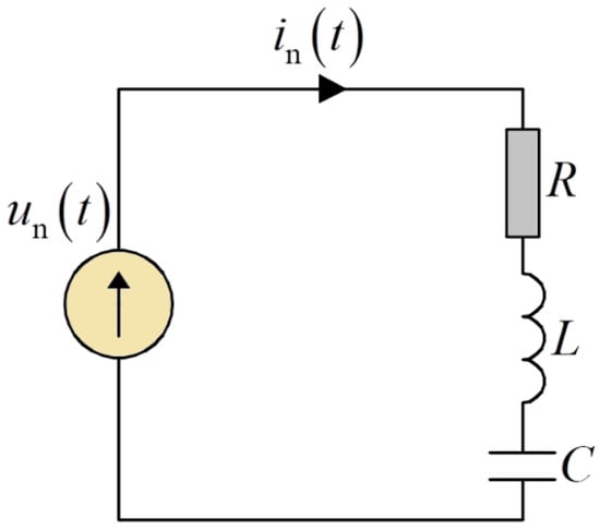
Figure 3.
Single-phase circuit scheme used for the theoretical analysis.

Table 1.
Combination of resistance, inductance, and capacitance values.
As a result of the supply voltage and load parameters that have been described, the equivalent load parameters’ values described by expressions (3), (5), and (7) are given in Table 2.

Table 2.
Comparison of the equivalent load parameters’ values.
By applying a voltage to the terminals of the load, the currents of the individual harmonics and the active and reactive powers [11] for the harmonics are received. All the achieved results, plus the RMS or sum values, are summarized in Table 3.

Table 3.
List of voltages, currents, and active and reactive powers’ values.
At the same time, the system shown in Figure 3 has an apparent power of 16,659.2 VA and a distortion power of 1793.6 VA.
The line current waveform of a single-phase load, before compensation, is presented in Figure 4.
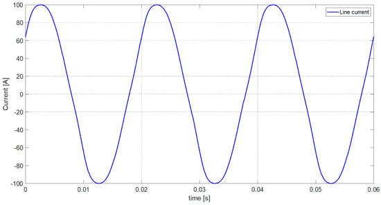
Figure 4.
The line current waveform of the single-phase load.
Based on the relationships for the active current (4), Budeanu reactive current (6), scattered current (10), and Budeanu complemented reactive current (12), the CRMS values of the individual component currents are listed in Table 4.

Table 4.
List of currents’ complex values in extended Budeanu theory.
Thereby, the RMS value of the scattered current is 5.611 A, and the Budeanu complemented reactive current is 5.316 A. The existence of both currents in the system causes the Budeanu distortion current to have two components. The RMS value of the Budeanu distortion current is equal to 7.729 A.
The component currents’ waveforms according to the developed Budeanu theory are presented in Figure 5.
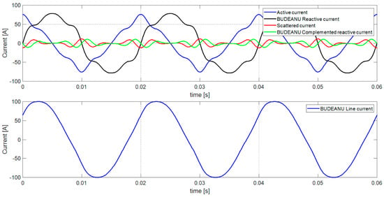
Figure 5.
The individual currents’ components and load current waveforms in extended Budeanu theory.
Figure 6, however, shows the distortion current waveform along with its components, namely, the scattered current and the Budeanu complemented reactive current.
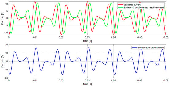
Figure 6.
The distortion current waveform in extended Budeanu theory.
Based on the relation (19), the power factor of the system shown in Figure 4 is
In the above theoretical illustration 1, it can be seen that a capacitor should be used to compensate for Budeanu’s reactive power. The selection of the capacitor capacity is based on Equation (25). After calculating the optimal value of the capacitor capacity for the system shown in Figure 3, the equivalent parameters of the load seen from the side of the power source changed. As a result of the change in the equivalent parameters, the component currents associated with the reactance elements change, and, consequently, so do the component powers. Below, Figure 7 shows the system with the connected capacitor with the optimal capacity.
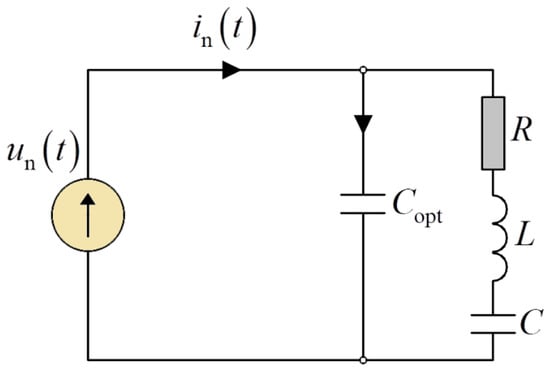
Figure 7.
The single-phase circuit with optimal capacity used for theoretical analysis.
Based on calculations ensuant from the ability to compensate for the equivalent susceptance of the entire system, the optimal capacitance is . The optimal capacity was determined from Equation (25), with the susceptance value for the fundamental harmonic replaced by the equivalent susceptance value of the entire system.
After applying a voltage to the terminals of the load, the following results for the equivalent parameters of the load were obtained. Table 5 summarizes the equivalent parameters of the load with the included optimal capacity.

Table 5.
List of equivalent load’s parameters’ values after optimal capacity connection.
Table 6 includes the harmonic currents and the active and reactive powers’ values after connecting a compensator to the equivalent susceptance for the whole system.

Table 6.
List of voltages and currents and also active power and reactive power values after optimal capacity connection.
After connecting the optimal capacity, as shown in Figure 7 and summarized in Table 6, it follows that the RMS value of current decreased from 71.79 A to 56.33 A. Therefore, Budeanu’s reactive power also decreased from 12964.1 var to 854.6 var and changed its character from inductive to capacitive. The compensated system has an apparent power of 13,071.7 VA and a distortion power of 7993.4 VA.
The line current waveform in a single-phase load after compensation with the optimal capacity is presented in Figure 8.
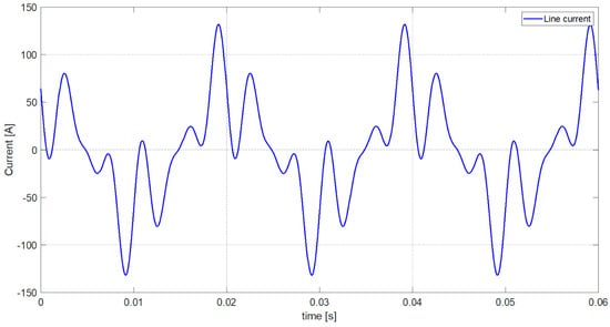
Figure 8.
The waveform of the line current of the single-phase load after optimal capacity connection.
Based on the relationships for the active current (4), Budeanu reactive current (6), scatter current (10), and Budeanu complemented reactive current (12), the CRMS values of the individual component currents after compensation with the optimal capacity are summarized in Table 7.

Table 7.
List of CRMS currents’ values in extended Budeanu theory after optimal capacity connection.
It can be observed from Table 7 that both the active current and the scattered current did not change their CRMS values because they are related to the resistive element. The component currents associated with the reactance elements of the system changee. While the Budeanu reactive current takes on a satisfactory CRMS, the CRMS of the Budeanu complemented reactive current significantly increases. This means that the RMS value of the scattered current is still 5.611 A, and the Budeanu complemented reactive current increases from a value of 5.316 A to a value of 33.986 A. The significant boost of the RMS value of the Budeanu complement reactive current impacts an increase in the RMS value of the Budeanu distortion current , which is now 34.446 A.
Figure 9 presents the component currents’ waveforms according to the extended Budeanu theory after the connection of the optimal capacity.
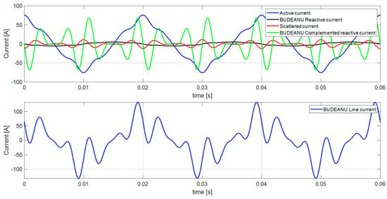
Figure 9.
The currents’ components and load current waveforms in developed Budeanu’s theory after optimal capacity connection.
Figure 10, in contrast, shows the waveform of the distortion current with its components, namely, the scattered current and the Budeanu complemented reactive current, after connecting the optimal capacity.
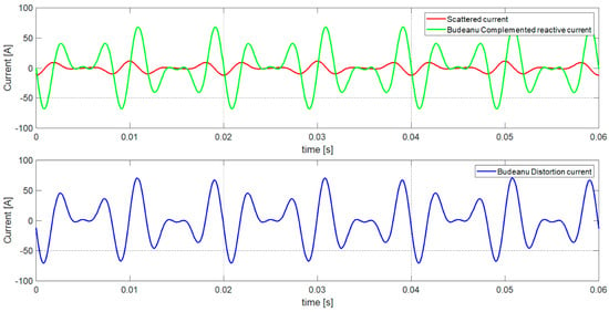
Figure 10.
The waveform of the distortion current in developed Budeanu’s theory after optimal capacity connection.
Based on the relation (19), the power factor of the system shown in Figure 8 is
5. Selected Structures of Passive Compensators—Part 2
Another type of reactance compensator is a combination of a series capacitor and choke (LC compensator) or a choke alone (L). Figure 11 shows the possible structures of the passive compensators discussed in this section.

Figure 11.
View of the structures of reactance compensators in the form of a series connection of a capacitor and a choke as well as a single choke.
The basic principle of selecting a compensator structure is simple. If, for the fundamental harmonic frequency, the susceptance has an inductive character, then the structure of the compensator of the LC-type should be selected [2,6,21]. This is related to the fact that above the fundamental harmonic frequency, the reactance of the LC-type compensator is inductive and does not cause resonant harmonic amplification. The second case involves an L-type compensator [2,6,21]. This is used when the capacitive nature of the susceptance is responsible for the Budeanu reactive current.
The first step in selecting the optimal parameters of an LC compensator is to choose the initiative capacitance , which is the capacitance needed for the total reactive power compensation of the fundamental harmonic. Most conveniently, the initiative capacitance is determined from the following relationship:
The second step is the choice of capacitance , which, as the relationship below shows, depends only on the choice of the resonance frequency , namely,
After calculating the capacitance of and choosing the resonant frequency , it is possible to choose the optimal inductance, depending on the aforementioned two parameters:
A slightly more difficult step is to determine, through an iterative relationship, the optimal capacity, i.e., the capacity through which the RMS value of the current of the power source (the component(s) associated with the reactance elements) can be minimized. This relationship takes the following form:
The final step is to check the resonant frequency limitation, that is, to satisfy the condition:
If everything is fine, then stay with the selected optimal inductance. If condition (32) is not satisfied, then another value of inductance is selected, and the calculation must be repeated.
If the susceptance of the load has a capacitive character, then a compensator built from the choke itself should be used. Accordingly, the relation (28) takes the following form:
The next step is to check whether the initiative inductance coincides with the optimal inductance, which is determined from the following relationship:
The design procedure outlined above is a simplified proceeding of the minimum needed to select the appropriate capacitance and inductance parameters. A more detailed description of the procedure for selecting LC and L compensator parameters can be found in [2,6].
6. Theoretical Illustration 2
For theoretical illustration 2, the same system as the one shown in Figure 3 was chosen. The difference is in the use of a different type of passive compensator built from an LC element. The design methodology and the relationships based on which appropriate capacitance and inductance parameters are selected are described in Section 5.
After calculating the optimal value of the capacitor capacity (31) and choosing the optimal value of the choke inductance (30) for the system presented in Figure 3, the equivalent load parameters observed from the power source change. As a result of the change in equivalent parameters, the component currents associated with the reactance elements change, and, consequently, so do the component powers. Below, Figure 12 shows a system with a connected capacitor with the optimal capacity and a choke with the optimal inductance.
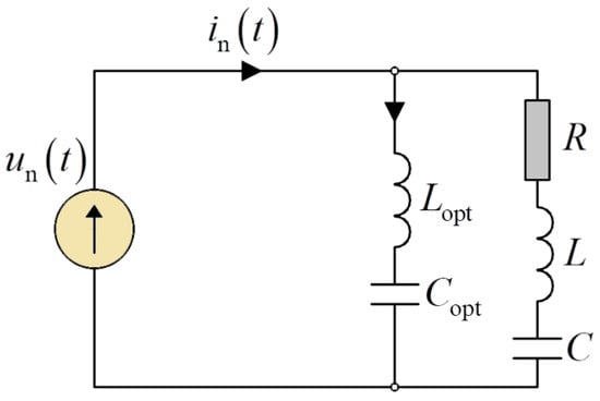
Figure 12.
Scheme of the single-phase system with optimal capacity and inductance used for theoretical calculations.
Based on calculations ensuant from the ability to minimize the Budeanu reactive current, the optimal capacitance is . In addition, given that the power system may be operated with no danger and that the currents do not resonate at the fundamental harmonic or the characteristic harmonics of the higher orders, an optimal inductance value for the of was selected. The optimal capacity was determined from Equation (31), with the susceptance values for individual harmonics replaced by the value of the equivalent susceptance of the whole system.
When voltage is applied to the system terminals, the following results for the equivalent load parameters were obtained. Table 8 lists the equivalent load parameters with the LC compensator connected.

Table 8.
List of the equivalent load parameters’ values after LC compensator connection.
Table 9 lists the harmonic currents and the active reactive powers’ values after connecting the minimizing compensator of the Budeanu reactive current.

Table 9.
The voltages, currents, active power, and reactive power values after LC compensator connection.
After connecting the LC compensator, as shown in Figure 12 and from the information in Table 9, the current’s RMS value decreased from 71.79 A to 44.885 A. At the same time, the reactive power also decreased from 12,964.1 var to 257.7 var. The compensated system has an apparent power of 10,415.9 VA and a distortion power of 1476.7 VA.
The line current waveform of a load after compensation with an LC compensator is presented in Figure 13.
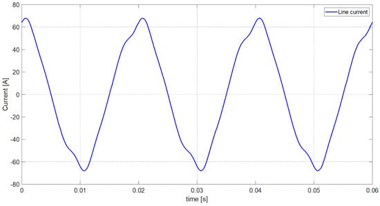
Figure 13.
The waveform of the line current of the single-phase load after LC compensator connection.
Based on the relationships for the active current (4), Budeanu reactive current (6), scattered current (10), and Budeanu complemented reactive current (12), the CRMS values of the individual component currents after minimizing the Budeanu reactive current are summarized in Table 10.

Table 10.
List of complex currents’ values in extended Budeanu theory after LC compensator connection.
As can be seen from Table 10, both the active current and the scattered current have not changed their CRMS because they are related to the resistive element. What did change was the component currents associated with the reactance elements of the system. The obtained CRMS values of the Budeanu reactive current and the Budeanu complemented reactive current are at a very good level. This means that the RMS value of the scattered current is still 5.611 A, and the value of the Budeanu complemented reactive current drops from 5.316 A to 3.002 A. The reduction in the RMS value of the Budeanu complemented reactive current impacts a reduction in the RMS value of the Budeanu distortion current , which equals 6.363 A.
Figure 14 presents the component currents’ waveforms according to the extended Budeanu theory after connecting the LC compensator.
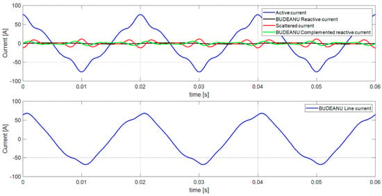
Figure 14.
The currents’ components and the load current waveforms in extended Budeanu theory after LC compensator connection.
Figure 15, in contrast, shows the waveform of the distortion current with its components, that is, the scattered current and the Budeanu complemented reactive current after the LC compensator is connected.
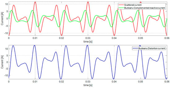
Figure 15.
The waveform of the distortion current in developed Budeanu’s theory after LC compensator connection.
Based on relation (19), the power factor of the system shown in Figure 12 is
7. Analysis of the Obtained Results
Table 11 lists the RMS values of the component currents and the percentage change relative to the value of the LTI load’s primary system for each solution, namely,

Table 11.
List of RMS values and percentage change from the currents’ values from the primary system in developed Budeanu’s theory before and after passive compensations.
- the RMS values of the component currents of the load shown in Figure 3;
- the RMS values of the component currents of the load shown in Figure 7;
- the RMS values of the component currents of the load shown in Figure 12.
As can be seen from the data listed in Table 11, both the RMS values of the active current and the scattered current do not change. This is following theoretical principles, which state that reactance elements do not have internal resistances. The omission of the resistance parameter in the design of passive compensators results in no change in the component currents associated with this quantity.
Further analyzing the values presented in Table 11, one can see a reduction in the RMS value of the Budeanu reactive current. This reaction of the reactive component of the Budeanu is observable both for the system with the selected optimal value of the capacitor capacity , which is 6.59% of the original value of the Budeanu reactive current (Figure 3). A lower value for the Budeanu reactive current was obtained when the LC compensator was placed in the system in Figure 12. This value equals 1.99% of the value of the Budeanu reactive component. It can, therefore, be considered that both approaches to reactive power reduction fulfill their expectations.
The situation is slightly different if looking at the RMS values of the Budeanu complement reactive current. In the system with the optimal capacitor capacity value, the RMS value of the Budeanu complemented reactive current increased by 639.3% compared to the original value shown in Figure 3, with a simultaneous increase in the distortion of the load’s current waveform, as shown in Figure 8. In the second type of compensator, i.e., the LC structure, the RMS value of the Budeanu complemented reactive current decreased by 43.53% compared to the original value, with an inconsiderable increase in the distortion of the load’s current waveform, as shown in Figure 13.
To closely follow the increase in the distortion of the load’s current waveform, it is necessary to look at Table 12.

Table 12.
List of chosen CRMS values of currents in extended Budeanu theory before and after passive compensations.
It can be seen from Table 12 that as the Budeanu complemented reactive current for higher harmonics increases, the distortion of the load current also increases. The increase in the CRMS value of the Budeanu complemented reactive current is a straight consequence of the increase in the susceptance for individual harmonics. The original system (Table 2) has inductive susceptances for each harmonic. The system, with the compensator in the form of the optimally selected capacitor capacitance (Table 5), has an inductive susceptance of a small value for the fundamental harmonic, whereupon for the third, fifth, and seventh harmonics it has capacitive susceptances, whose values increase when the harmonic order increases. Relating the susceptance parameter to the voltage of the individual harmonic, we obtain the value of the Budeanu complemented reactive current, which, as can be seen from Table 12, has a significant value around the value of the current of the individual harmonics and, thus, deforms the current waveform of the load to a lower (Figure 3 and Figure 12) or higher level (Figure 7).
The information in Table 11 and Table 12 is summarized very well by the power factor . The smaller the RMS value of the individual component currents, i.e., the scattered current, the Budeanu reactive current, and the Budeanu complemented reactive current in the load current relative to the active current, is, then the higher the value of the power factor is.
8. Conclusions
The studies presented in this publication indicate that it is possible to select the parameters of a compensator with the optimal capacity or optimal inductance. In the extended Budeanu theory, the equivalent susceptance of the whole system represents the Budeanu reactive current. Based on this equivalent parameter, the selection of the optimal capacity is not affected by the occurrence of resonant gain since, in systems with nonsinusoidal waveforms, the equivalent susceptance is different from the susceptance for the fundamental harmonic.
The second type of compensator discussed in this paper is designed using the Currents’ Physical Components (CPC) theory. In theoretical illustration 2 shown above, the LC compensator not only significantly compensates for the Budeanu reactive current but also reduces the RMS value of the Budeanu complemented reactive current. In addition, it slightly affects the deformation of the load current waveform and contributes to a decrease in the RMS value of the Budeanu distortion current.
Both of the discussed passive compensator structures have the effect of limiting the RMS value of the LTI load current. Picking the optimal capacity reduces the RMS value of the load current and the RMS value of the Budeanu reactive current while increasing the Budeanu complemented reactive current, the Budeanu distortion current, and, thus, the Budeanu distortion power. The LC structure reduces the RMS value of the load current and the RMS value of the Budeanu reactive current while minimizing the Budeanu complemented reactive current, the Budeanu distortion current, and the Budeanu distortion power.
Author Contributions
Conceptualization, Z.S., M.Z. and A.B.; methodology, Z.S.; software, Z.S.; validation, Z.S. and M.Z.; formal analysis, Z.S.; investigation, Z.S.; resources, Z.S.; data curation, Z.S.; writing—original draft preparation, Z.S. and M.Z.; writing—review and editing, Z.S., M.Z. and A.B.; visualization, Z.S.; supervision, M.Z. and A.B.; project administration, Z.S.; funding acquisition, Z.S. and M.Z. All authors have read and agreed to the published version of the manuscript.
Funding
This work was supported by the Ministry of Science and Higher Education in Warsaw, Poland, at the Białystok University of Technology in Białystok, Poland, under research subsidies no. WZ/WE-IA/7/2023 and no. WZ/WE-IA/3/2023.
Institutional Review Board Statement
Not applicable.
Informed Consent Statement
Not applicable.
Data Availability Statement
Data are contained within the article.
Conflicts of Interest
The authors declare no conflicts of interest.
References
- Budeanu, C.I. Puissances Reactives et Fictives; Institut Romain de l’Energie.: Bucharest, Romania, 1927. [Google Scholar]
- Czarnecki, L.S. Powers in Electrical Circuits with Non-Sinusoidal Current and Voltage Waveforms; Publishing Office of the Warsaw University of Technology: Warsaw, Poland, 2005. (In Polish) [Google Scholar]
- Torre, F.D.; Morando, A.P.; Sapienza, G. Power quality analysis of electromechanical energy conversion: A Budeanu approach. In Proceedings of the 14th International Conference on Harmonics and Quality of Power-ICHQP 2010, Bergamo, Italy, 26–29 September 2010; pp. 1–5. [Google Scholar]
- Czarnecki, L.S. Budeanu and Fryze: Two frameworks for interpreting power properties of circuits with nonsinusoidal voltages and currents. Electr. Eng. 1997, 80, 359–367. [Google Scholar] [CrossRef]
- Czarnecki, L.S. What is wrong with the Budeanu Concept of reactive and distortion power and why it should be abandoned. IEEE Trans. Instrum. Meas. 1987, IM-36, 834–837. [Google Scholar] [CrossRef]
- Czarnecki, L.S. Considerations on the reactive power in nonsinusoidal situations. IEEE Trans. Instrum. Meas. 1985, IM-34, 399–404. [Google Scholar] [CrossRef]
- Jeltsema, D. Budeanu’s Concept of reactive and distortion power revisited. In Proceedings of the 2015 International School on Nonsinusoidal Currents and Compensation (ISNCC), Lagow, Poland, 15–18 June 2015; pp. 68–73. [Google Scholar]
- Willems, J.L. Budeanu’s reactive power and realted concepts revisited. IEEE Trans. Instrum. Meas. 2011, 60, 1182–1186. [Google Scholar] [CrossRef]
- Nowomiejski, Z. Generalized theory of electric power. Arch. Elektrotechnik 1981, 63, 177–182. [Google Scholar] [CrossRef]
- Zajkowski, K. Disadvantages of power theory in single-phase circuits according to Budean and Fryse. Exp. Tests 2016, 12, 1500–1504. (In Polish) [Google Scholar]
- Sołjan, Z.; Zajkowski, M. Extension and correction of Budeanupower theory based on Currents’ Physical Components (CPC) theory for single-phase systems. Energies 2022, 15, 8321. [Google Scholar] [CrossRef]
- Czarnecki, L.S. Converter of the optimal capacitance to DC voltage. Electron. Lett. 1987, 17, 427–428. [Google Scholar]
- Chen, Z.; Blaabjerg, F.; Pedersen, J.K. A study of parallel operations of active and passive filters. In Proceedings of the 2002 IEEE 33rd Annual IEEE Power Electronics Specialists Conference, Cairns, Australia, 23–27 June 2002; Volume 2. [Google Scholar]
- Gumilar, L.; Cahyani, D.E.; Afandi, A.N.; Monika, D.; Rumokoy, S.N. Optimalization harmonic shunt passive filter using detuned reactor and capacitor bank to improvement power quality I hybrid power plant. In Proceedings of the ICIMECE 2019, Surakarta, Indonesia, 17–18 September 2019; AIP Conference Proceedings. Volume 2217, p. 030003. [Google Scholar]
- Jou, H.L.; Wu, J.C.; Wu, K.D. Parallel operation of passive power filter and hybrid power filter for harmonic suppression. IEE Proc.-Gener. Transm. Distrib. 2001, 148, 8–14. [Google Scholar] [CrossRef]
- Das, J.C. Passive filters—Potentialities and limitations. IEEE Trans. Ind. Appl. 2004, 40, 232–241. [Google Scholar] [CrossRef]
- Stefane, C. Investigation on the work efficiency of the LC passive harmonic filter chosen topologies. Electronics 2021, 10, 896. [Google Scholar]
- Akagi, H. Modern active filters and traditional passive filters. Bull. Pol. Acad. Sci. Tech. Sci. 2006, 54, 255–269. [Google Scholar]
- Shepherd, W.; Zakikhani, P. Suggested definition of reactive power for nonsinusoidal systems. Proc. Inst. Electr. Eng. 1972, 119, 1361–1362. [Google Scholar] [CrossRef]
- Kusters, N.L.; Moore, W.J.M. On the definition of reactive power under nonsinusoidal condition. IEEE Trans. Pow. Appl. Syst. 1980, PAS-99, 1845–1854. [Google Scholar] [CrossRef]
- Sołjan, Z.; Hołdyński, G.; Zajkowski, M. CPC-based minimizing of balancing compensators in four-wire nonsinusoidal asymmetrical systems. Energies 2021, 14, 1815. [Google Scholar] [CrossRef]
- Czarnecki, L.S. Currents’ Physical Components (CPC)-based power theory a review part II: Filters and reactive, switching and hybrid compensators. Przegląd Elektrotechniczny 2020, 20, 3–13. [Google Scholar]
- Czarnecki, L.S. Minimisation of distortion power of nonsinusoidal source applied to linear loads. Proc. IEE 1981, 128, 208–210. [Google Scholar] [CrossRef]
- Czarnecki, L.S. Minimisation of unbalanced and reactive currents in three-phase asymmetrical circuits with nonsinusoidal voltage. IEE Proc. B 1992, 139, 347–354. [Google Scholar] [CrossRef]
- Czarnecki, L.S. Minimization of reactive power under nonsinusoidal conditions. IEE Trans. Instrum. Meas. 1987, 36, 18–22. [Google Scholar] [CrossRef]
- Rahmani, S.; Hamadi, A.; Al-Haddad, K. A Lyapunov-Function-Based control for a three-phase shunt hybrid active filter. IEEE Trans. Ind. Electron. 2012, 59, 1418–1429. [Google Scholar] [CrossRef]
- Abdullah, A.; Biswal, G.R.; Roy, A.K. Modeling and control of hybrid power filter using p-q theory. In Proceedings of the IEEE 1st International Conference on Power Electronics, Intelligent Control and Energy Systems (ICPEICES), Delhi, India, 4–6 July 2016; pp. 1–6. [Google Scholar]
- Czarnecki, L.S.; Almousa, M. Adaptive Balancing of Three-Phase Loads at Four-Wire Supply with Reactive Compensators and Nonsinusoidal Voltage. In Proceedings of the 2020 IEEE Texas Power and Energy Conference (TPEC), College Station, TX, USA, 6–7 February 2020; pp. 1–6. [Google Scholar]
- Graczyk, A. Determination of parameters for a half-band filter in a digital Hilbert transformer in a reactive power measurement system. Przegląd Elektrotechniczny 2015, 91, 104–108. [Google Scholar] [CrossRef][Green Version]
- Dmitruk, K. Predictive-SVM control method dedicated to the AC/DC converter with the LCL grid filter. Bull. Pol. Acad. Sci. Tech. Sci. 2020, 68, 1–8. [Google Scholar][Green Version]
- Bellia, L.; Błaszczak, U.; Fragliasso, F.; Gryko, L. Matching CIE illuminants to measured spectral power distributions: A method to evaluate non-visual potential of daylight in two European cities. Sol. Energy 2020, 208, 830–858. [Google Scholar] [CrossRef]
- Ackermann, B.; Schulz, V.; Martiny, C.; Hilgers, A.; Zhu, X. Control of LEDs. In Proceedings of the Conference Record of the 2006 IEEE Industry Applications Conference Forty-First IAS Annual Meeting, Tampa, FL, USA, 8–12 October 2006; pp. 2608–2615. [Google Scholar]
- Apse-Apsitis, P.; Avotins, A.; Ribickis, L. Wirelessly controlled led lighting system. In Proceedings of the 2012 IEEE International Energy Conference and Exhibition (ENERGYCON), Florence, Italy, 9–12 September 2012; pp. 952–956. [Google Scholar]
- Nair, A.; Arunraj; Kumar, N.; Ramya, J.C. Performance analysis of LED and florescent lamps a case study of street lihgtning system. In Proceedings of the ICEETS, Nagercoil, India, 7–8 April 2016. [Google Scholar]
- Davidovic, M.; Djordjevic, N.; Mikulovic, J.; Kostic, M.; Radakovic, Z. Voltage distortion in LED street lighting installations. Electr. Eng. 2021, 103, 2161–2180. [Google Scholar] [CrossRef]
- Kurkowski, M.; Popławski, T.; Zajkowski, M.; Kurkowski, B.; Szota, M. Effective Control of road luminnaires—A case study on an example of a selected city in Poland. Energies 2022, 15, 5378. [Google Scholar] [CrossRef]
- Popławski, T.; Kurkowski, M.; Mirowski, J. Improving the quality of electricity in instllations with mixed lighting fittings. Energies 2020, 13, 6017. [Google Scholar] [CrossRef]
- Hachemi, G.; Abdelkader, H.; Rachid, D. Optimal sizing of passive filters for typical industrial power systems. Appl. Mech. Mater. 2022, 905, 65–77. [Google Scholar] [CrossRef]
- Shakeri, S.; Esmaeili, S.; Rezaeian, M.H. Passive harmonic filter design considering voltage sag performance—Applicable to large industries. IEEE Trans. Power Deliv. 2022, 37, 1714–1722. [Google Scholar] [CrossRef]
- Sierocka, H.; Zajkowski, M.; Hołdyński, G.; Sołjan, Z. Characteristics of electricity consumption on the example of poultry farming in Poland. Energies 2023, 16, 547. [Google Scholar] [CrossRef]
- Vresdian, D.J.; Al-Yousif, S.; Mnati, M.J.; Tofigh, M.A. Various passive filter designs proposed for harmonic exteunation in industrial distribution systems. Int. J. Eng. Technol. 2018, 7, 75–84. [Google Scholar]
- Ayaz, M.S.; Aljarrah, R.; Salem, Q.; Al-Omary, M.; Abuishmais, I.; Al-Rousan, W. Application of passive harmonic filters in power distribution system with high share of PV systems and non-linear loads. Int. J. Renew. Energy Res. 2023, 13, 401–411. [Google Scholar]
- Argüello, A.; Torquato, R.; Freitas, W. Passive filter tunning for harmonic resonance mitigation in Wind Park. IEEE Trans. Power Deliv. 2023, 38, 3834–3846. [Google Scholar] [CrossRef]
- Jayaraman, M. Passive filter topologies for grid connected and standalone PV systems: A survey. ECS Trans. 2022, 107, 12083–12095. [Google Scholar] [CrossRef]
- Karaca, M.; Mamizadeh, A.; Genc, N.; Sular, A. Analysis of passive filters for PV inverters under variable irradiances. In Proceedings of the 2019 8th International Conference on Renewable Energy Research and Applications (ICRERA), Brasov, Romania, 3–6 November 2019. [Google Scholar]
- Zhang, Z.; Pang, H.; Georgiadis, A.; Cecati, C. Wireless Power Transfer—An overview. IEEE Trans. Ind. Electron. 2018, 66, 1044–1058. [Google Scholar] [CrossRef]
- Lee, C.H.; Jung, G.; Al Hosani, K.; Song, B.; Seo, D.-K.; Cho, D. Wireless Power Transfer system for an autonomous electric vehicle. In Proceedings of the 2020 IEEE Wireless Power Transfer Conference (WPTC), Seoul, Republic of Korea, 15–19 November 2020; pp. 467–470. [Google Scholar]
- Stankiewicz, J.M.; Choroszucho, A.; Steckiewicz, A. Estimation of the maximum efficiency and the load power in the periodic WPT systems using numerical and circuit models. Energies 2021, 14, 1151. [Google Scholar] [CrossRef]
- Choroszucho, A.; Pieńkowski, C.; Jordan, A. Electromagnetic wave propagation into building constructions. Przegląd Elektrotechniczny 2008, 84, 44–49. [Google Scholar]
- Stankiewicz, J.M. Analysis of the Influence of the Skin Effect on the Efficiency and Power of the Receiver in the Periodic WPT System. Energies 2023, 16, 2009. [Google Scholar] [CrossRef]
- Hui, S.Y.R. Wireless Power Transfer: A brief review & update. In Proceedings of the 2013 5th International Conference on Power Electronics Systems and Applications(PESA), Hong Kong, China, 11–13 December 2013; pp. 1–4. [Google Scholar]
- Li, H.; Wang, S.; Zhang, C.; Wang, Z. A compact passive-active hybrid EMI filter with phase compensation for power converters. In Proceedings of the 4th Interational Conference on Smart Power & Internet Energy Systems, Beijing, China, 9–12 December 2022. [Google Scholar]
- Pasko, M.; Szymczak, M. Comparison of active and passive EMI filters to reduction conducted noise. ITM Web Conf. 2018, 19, 01002. [Google Scholar] [CrossRef]
- Biela, J.; Wirthmueller, A.; Waespe, R.; Heldwein, M.L.; Raggl, K.; Kolar, J.W. Passive and active hybrid integrated EMI filters. IEEE Trans. Power Electron. 2009, 24, 1340–1349. [Google Scholar] [CrossRef]
- Hołdyński, G.; Sołjan, Z.; Zajkowski, M. CPC-based reactive compensation at three-phase four-wire systems powered from asymmetric sinusoidal voltage source. In Proceedings of the 18th International Scientific Conference on Electric Power Engineering (EPE), Kouty nad Desnou, Czech Republic, 15–17 May 2019; pp. 395–400. [Google Scholar]
Disclaimer/Publisher’s Note: The statements, opinions and data contained in all publications are solely those of the individual author(s) and contributor(s) and not of MDPI and/or the editor(s). MDPI and/or the editor(s) disclaim responsibility for any injury to people or property resulting from any ideas, methods, instructions or products referred to in the content. |
© 2023 by the authors. Licensee MDPI, Basel, Switzerland. This article is an open access article distributed under the terms and conditions of the Creative Commons Attribution (CC BY) license (https://creativecommons.org/licenses/by/4.0/).