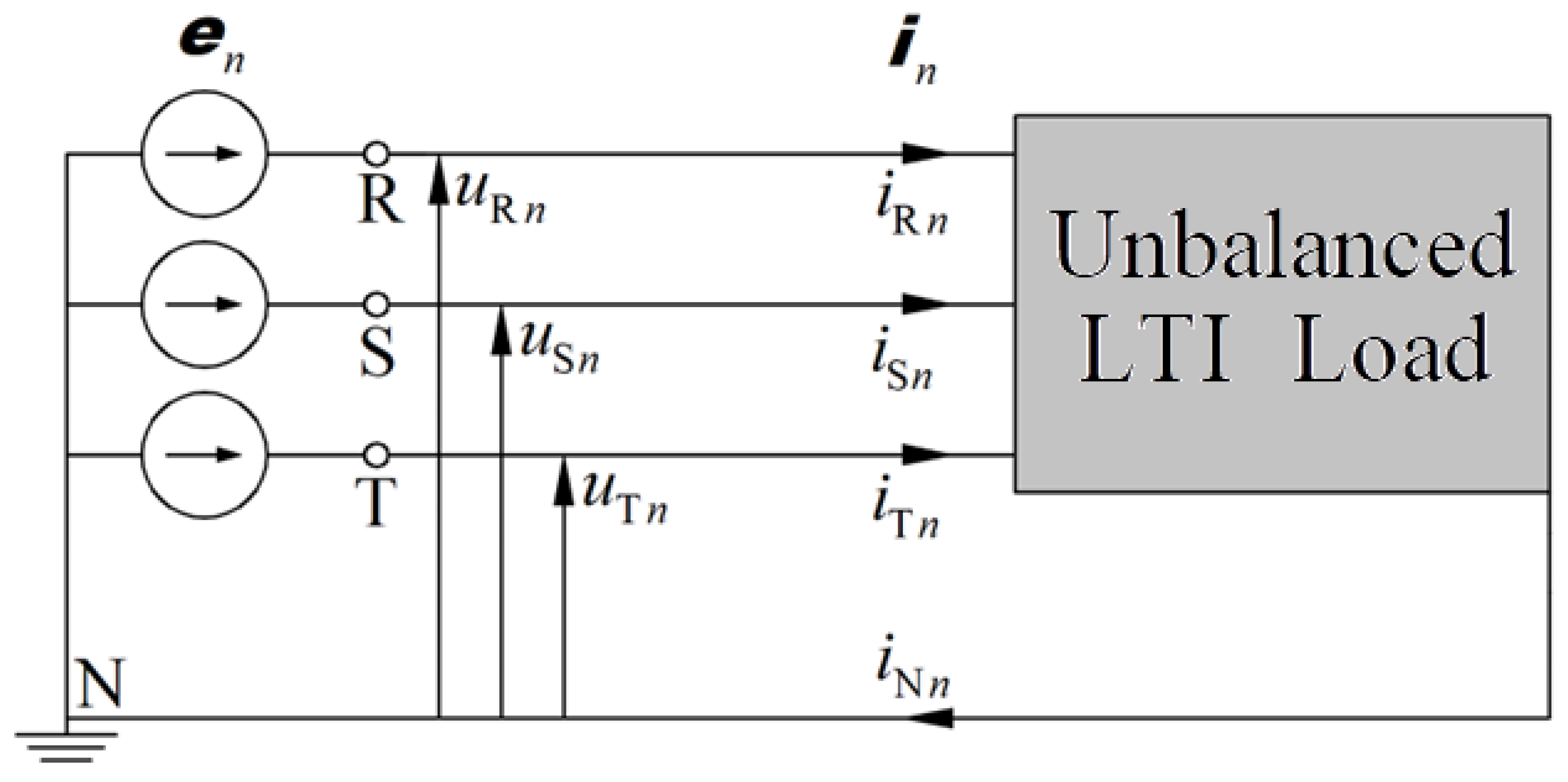
Figure 1.
Unbalanced LTI load powered from nonsinusoidal symmetrical voltage source.
Figure 1.
Unbalanced LTI load powered from nonsinusoidal symmetrical voltage source.
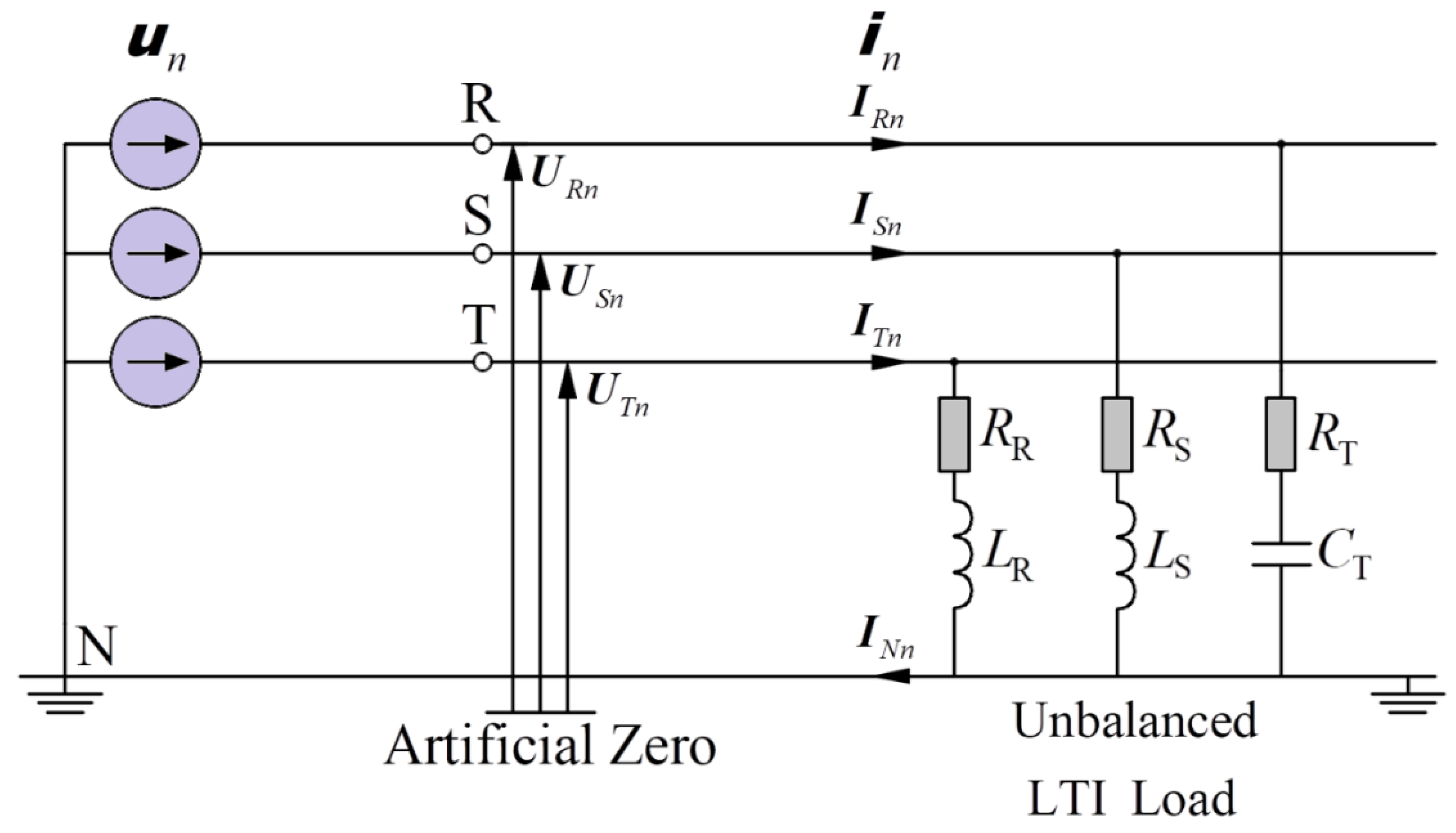
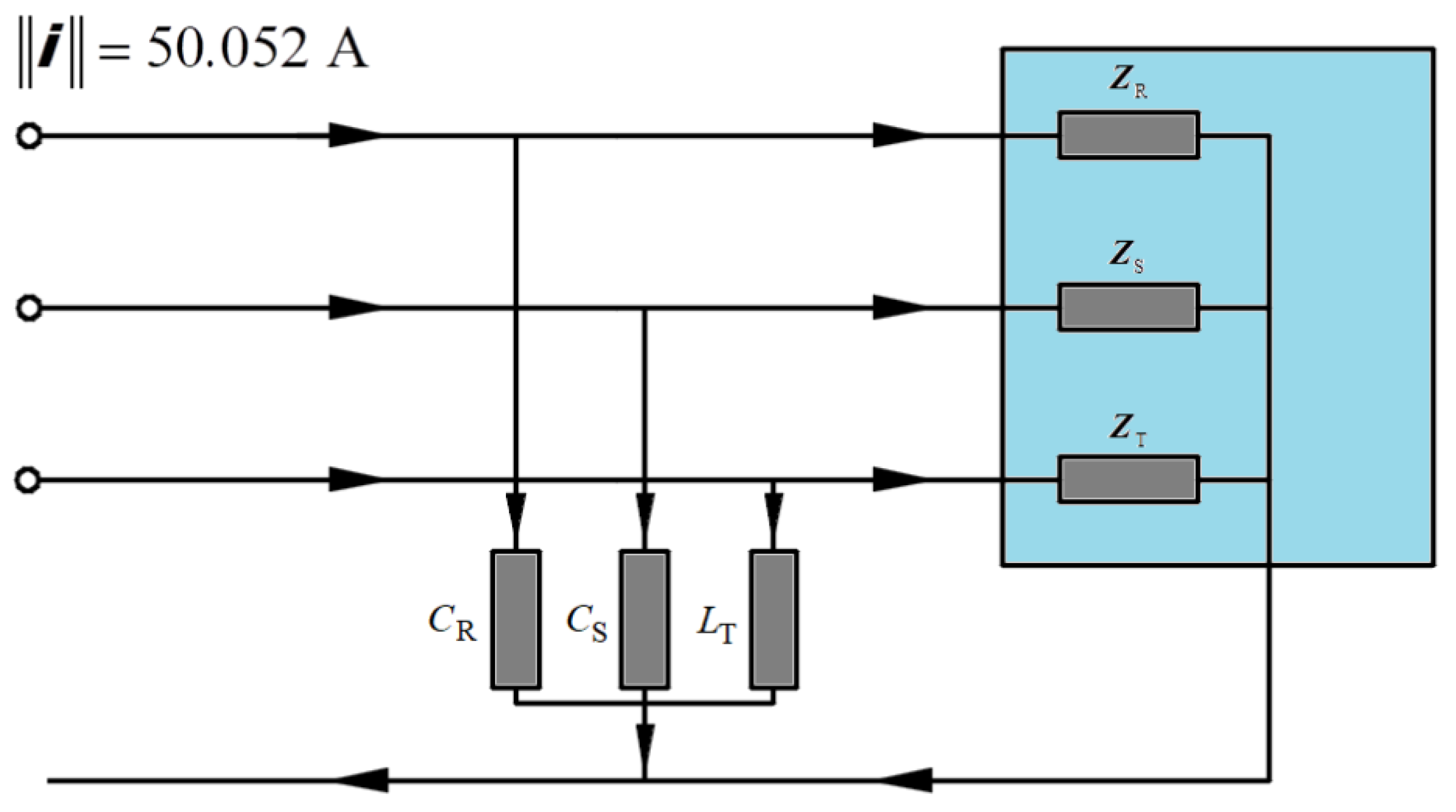
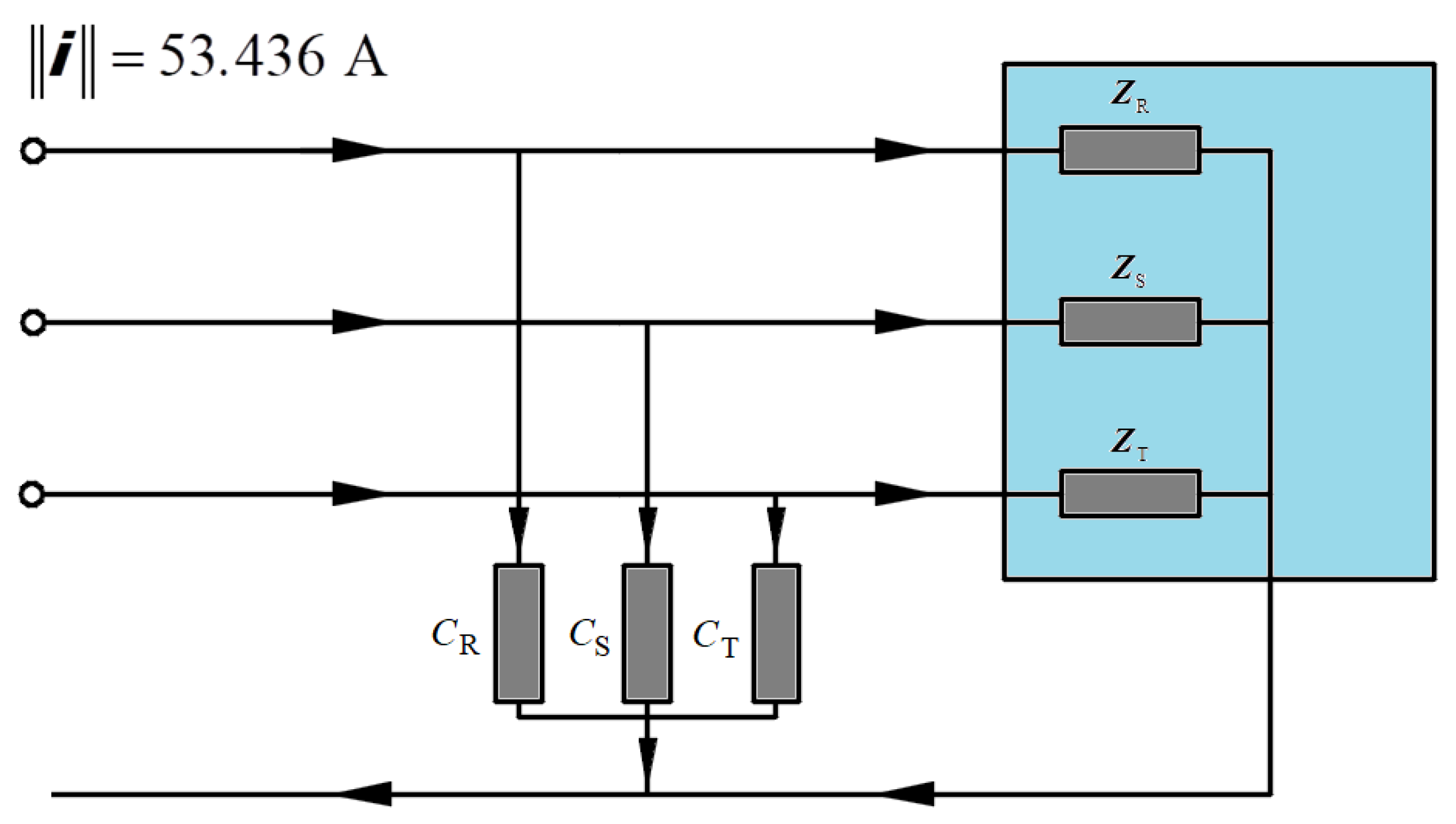
Figure 2.
Scheme of a load chosen for theoretical illustration 1.
Figure 2.
Scheme of a load chosen for theoretical illustration 1.
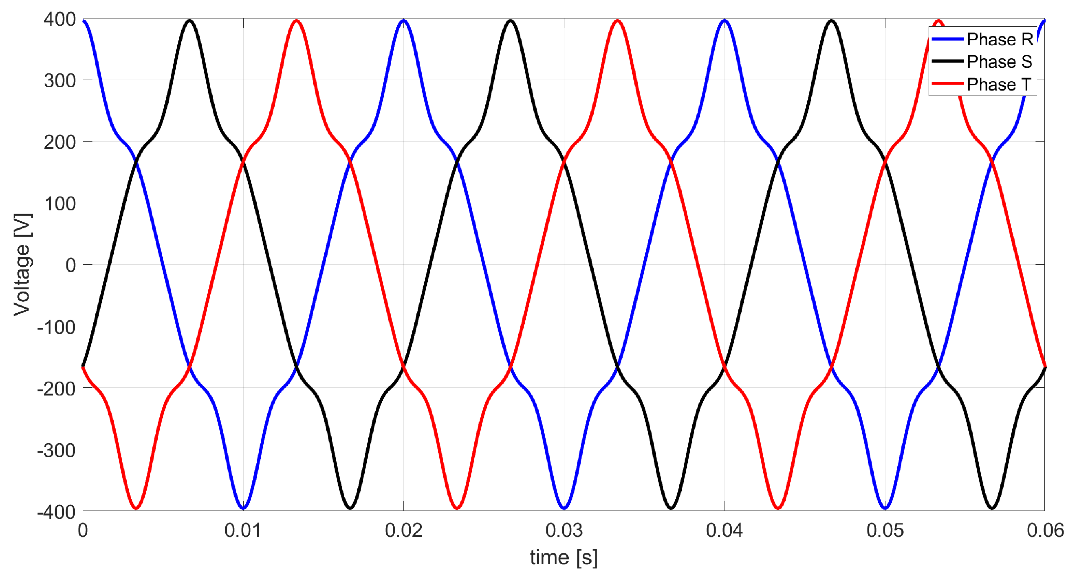
Figure 3.
Nonsinusoidal voltage waveforms at the terminals of a three-phase LTI load.
Figure 3.
Nonsinusoidal voltage waveforms at the terminals of a three-phase LTI load.
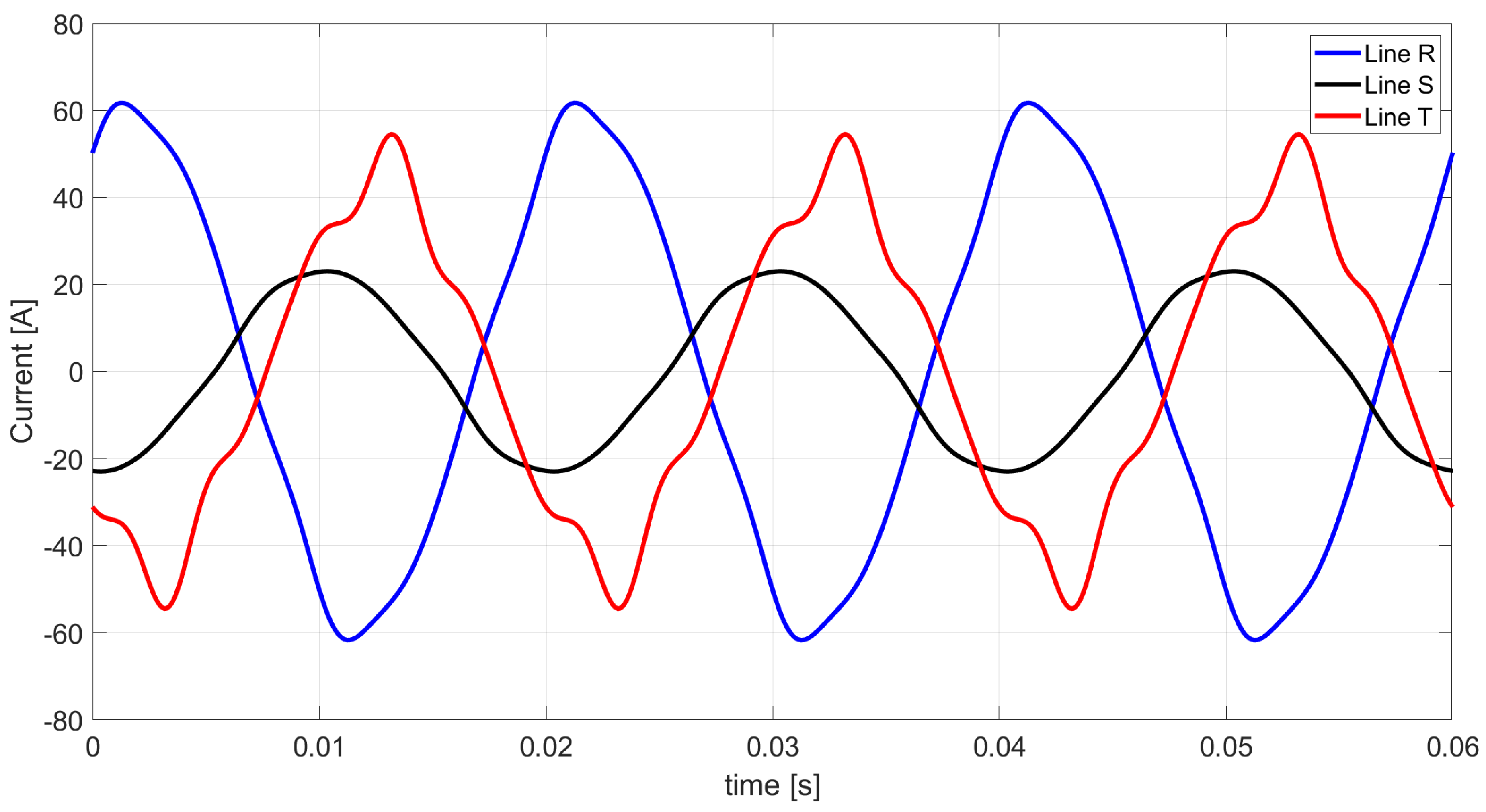
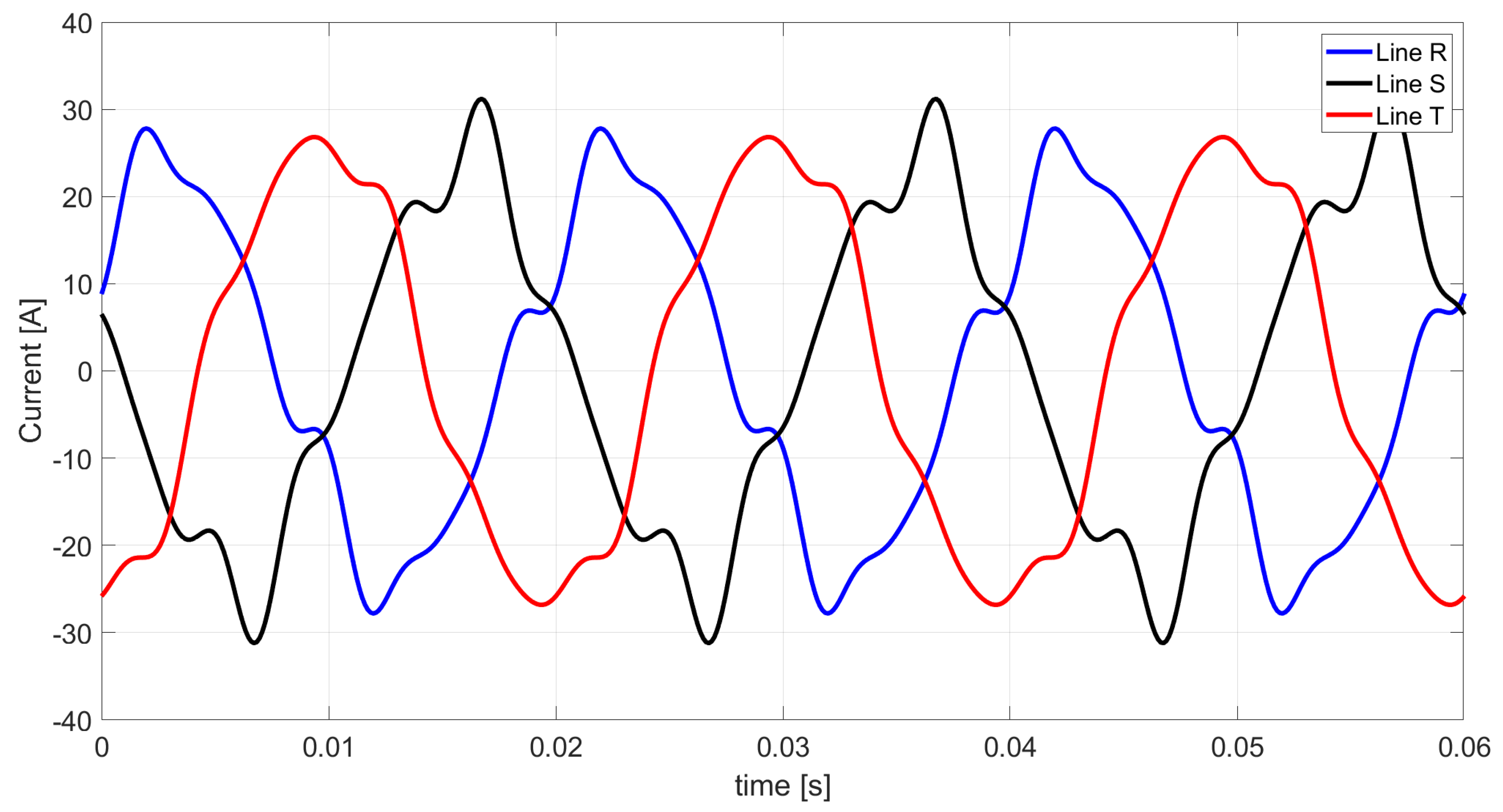
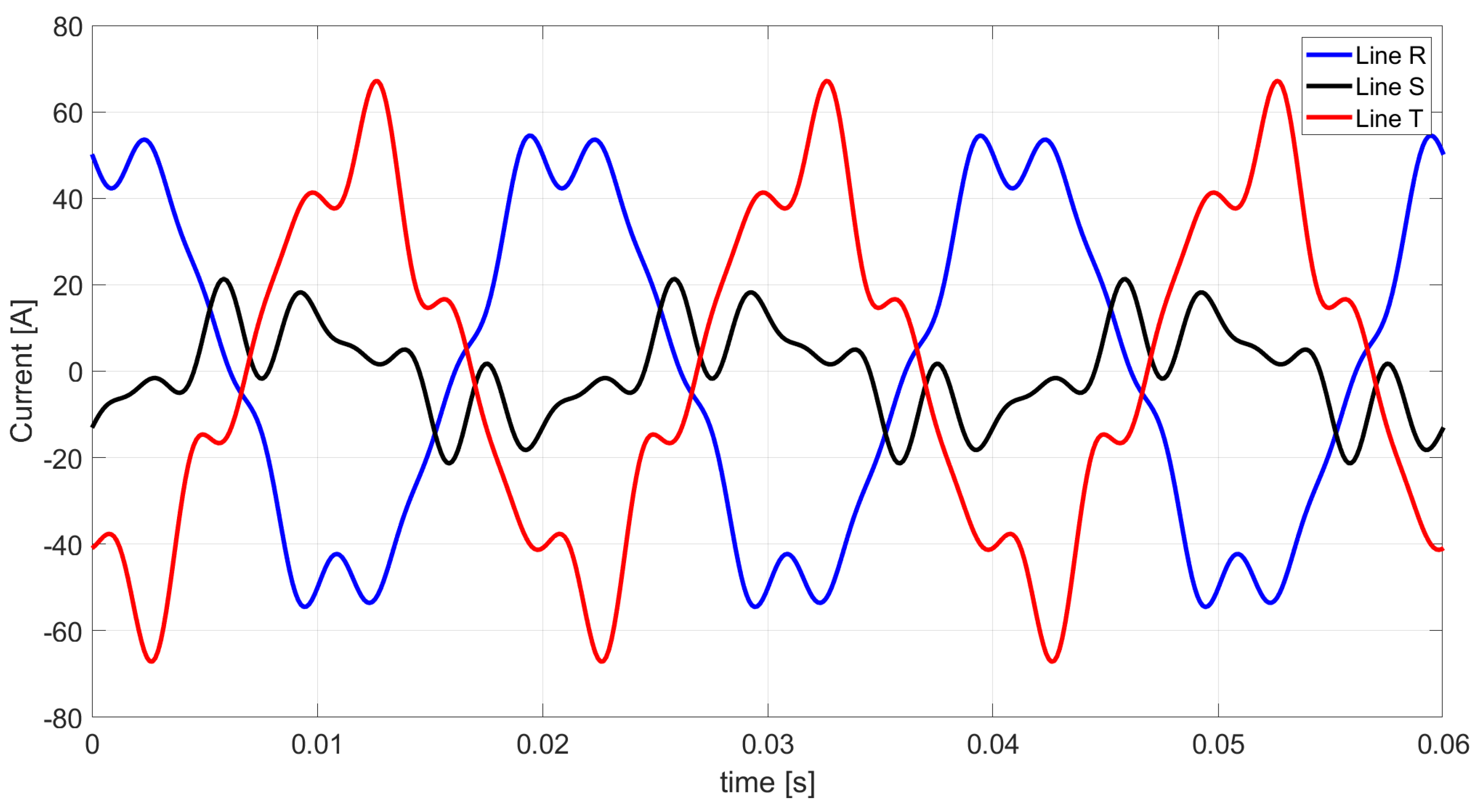
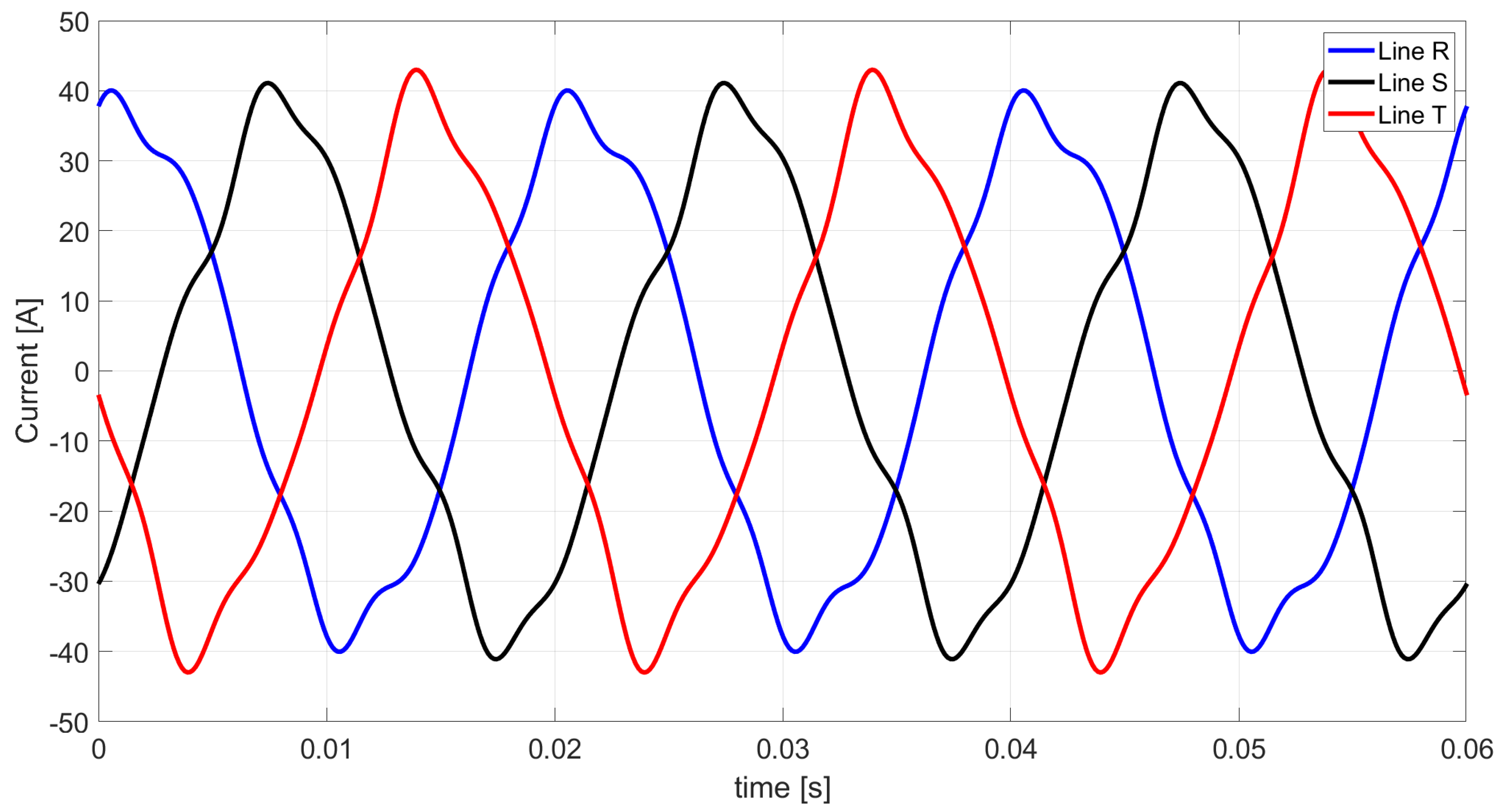
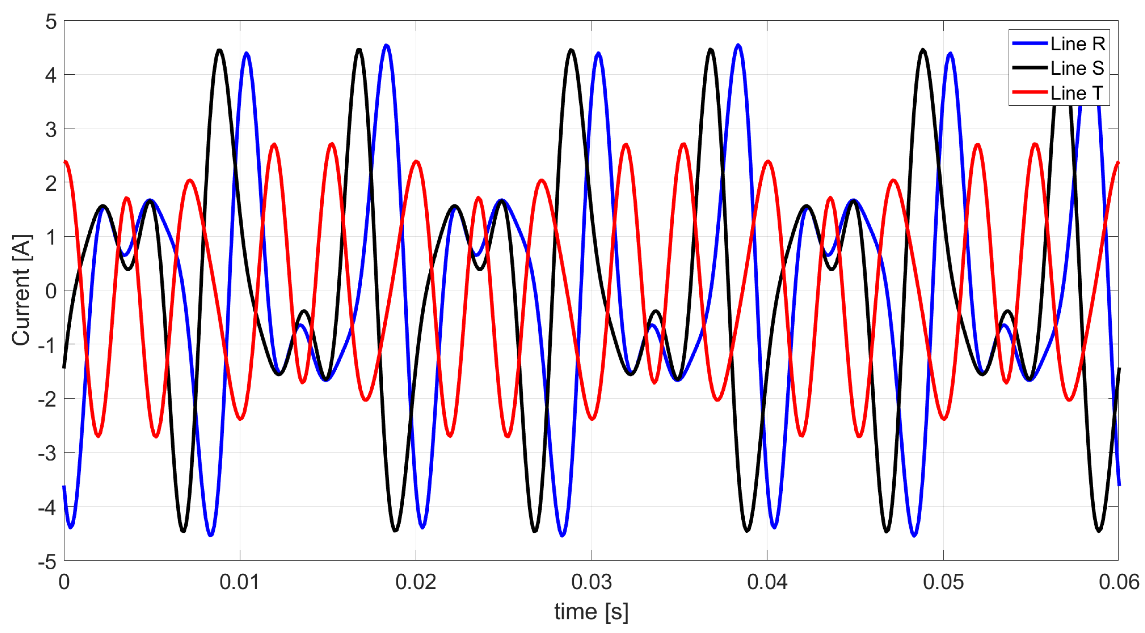
Figure 4.
Line currents waveforms achieved from Ohm’s law and Kirchhoff’s law.
Figure 4.
Line currents waveforms achieved from Ohm’s law and Kirchhoff’s law.
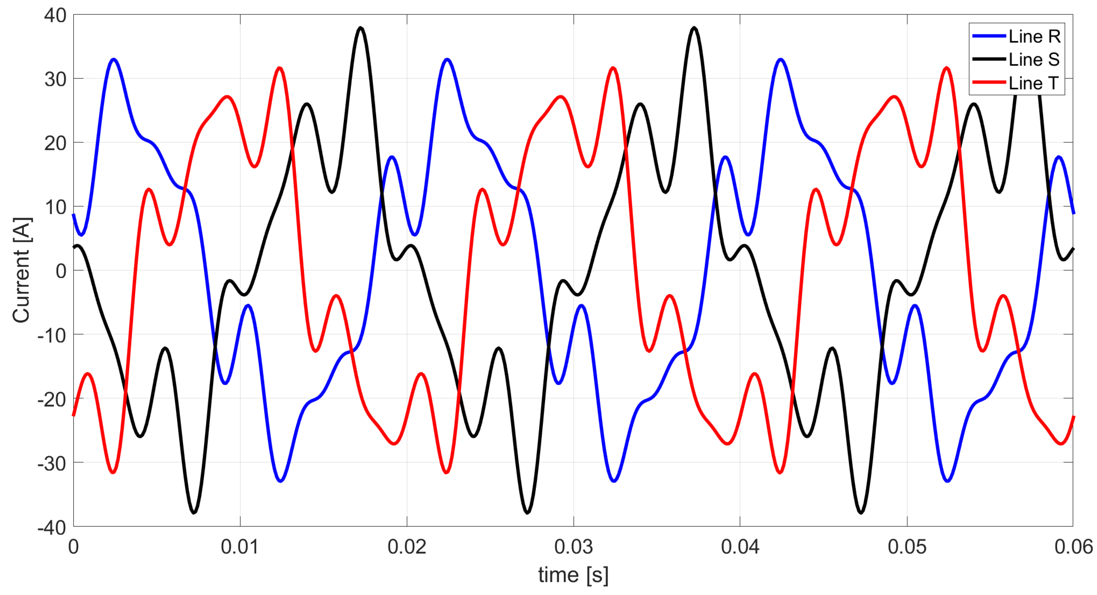
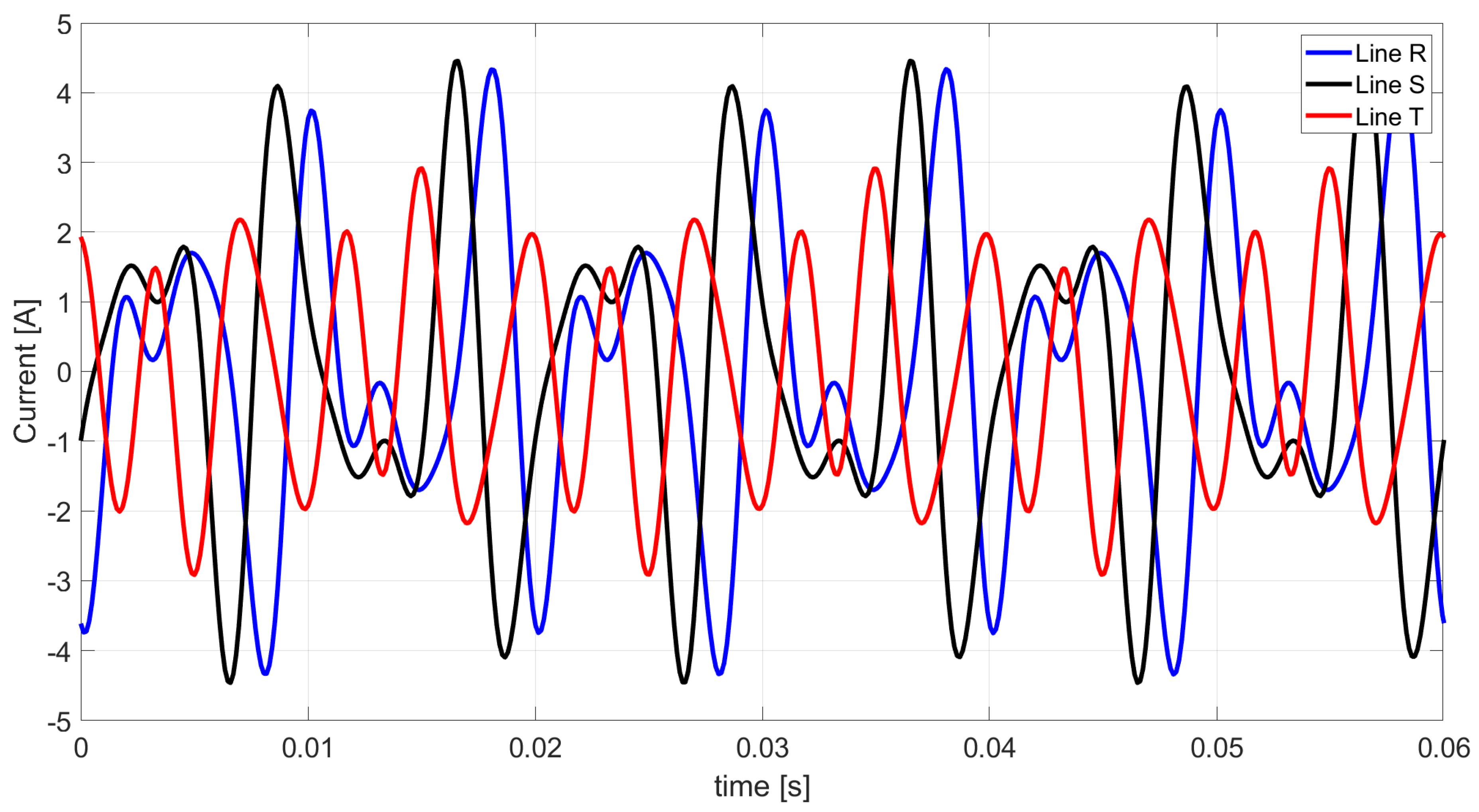
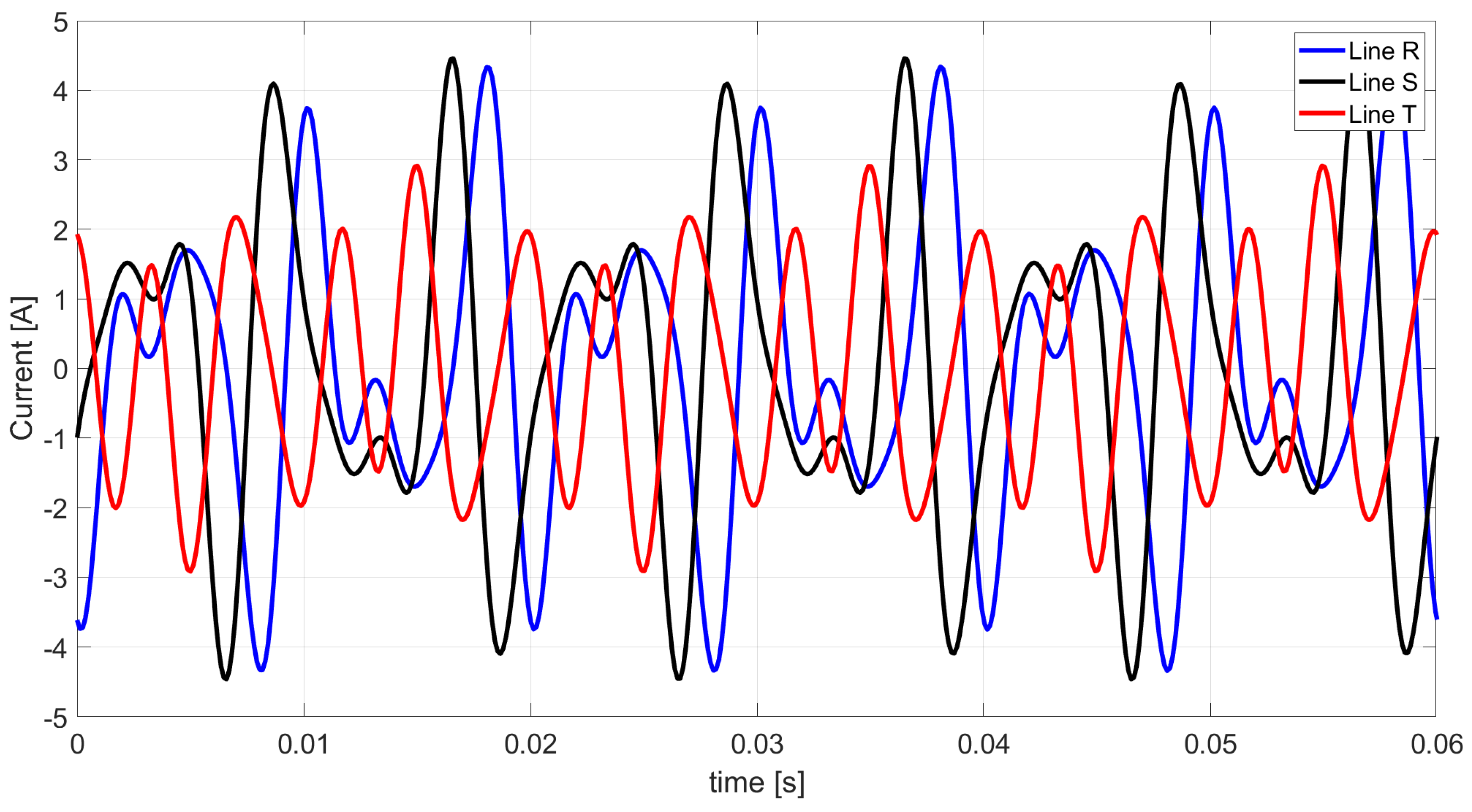
Figure 5.
The waveforms of the Budeanu distortion current following the developed Budeanu theory.
Figure 5.
The waveforms of the Budeanu distortion current following the developed Budeanu theory.
Figure 6.
Primary circuit with the connected ideal compensator compensating for the reactive current of the first harmonic.
Figure 6.
Primary circuit with the connected ideal compensator compensating for the reactive current of the first harmonic.
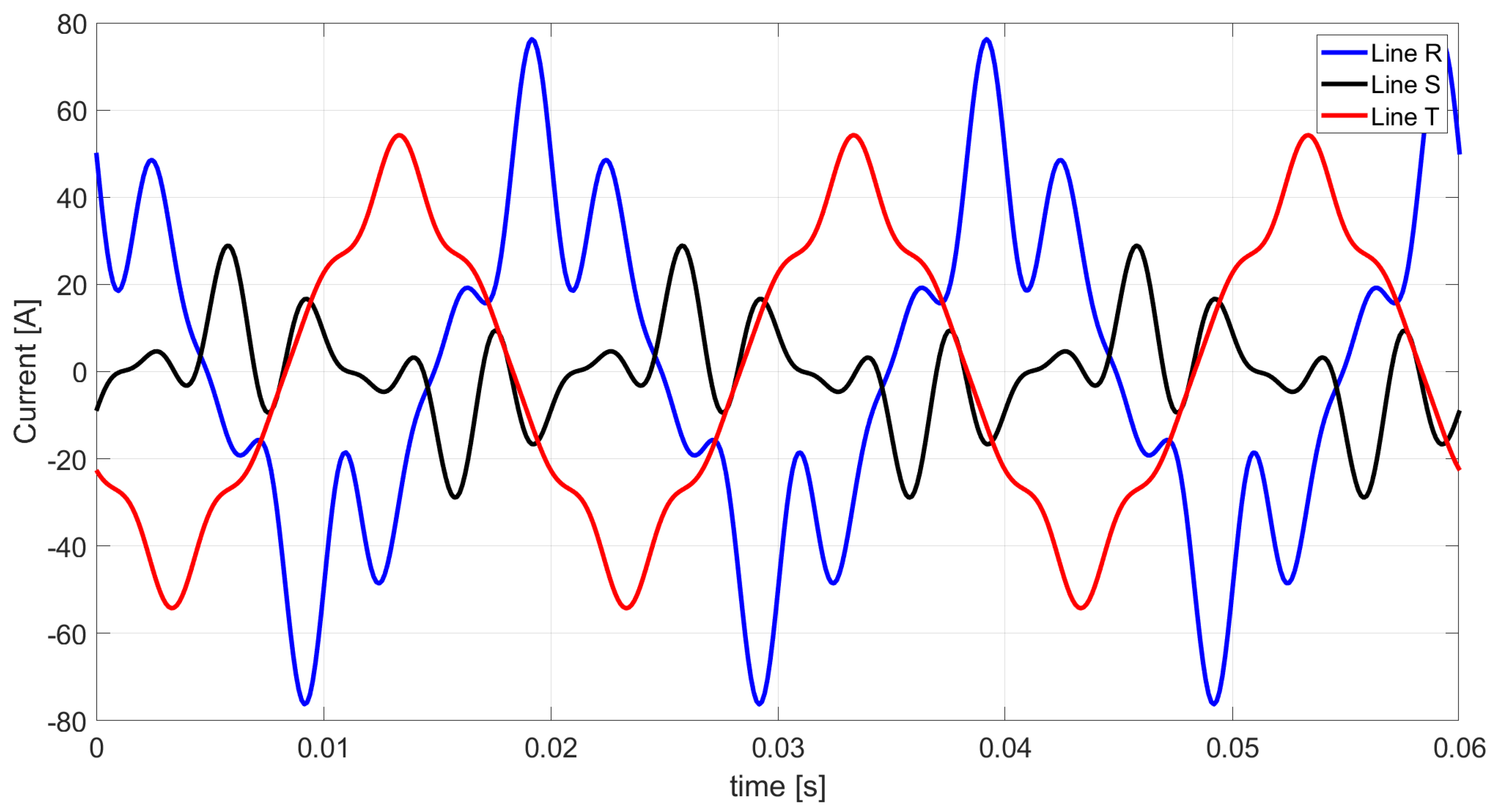
Figure 7.
The line currents waveforms based on Ohm’s law and Kirchhoff’s law after the connection of a reactive current compensator of the first harmonic.
Figure 7.
The line currents waveforms based on Ohm’s law and Kirchhoff’s law after the connection of a reactive current compensator of the first harmonic.
Figure 8.
The Budeanu distortion current waveforms according to the developed Budeanu theory after reactive current compensation of the first harmonic.
Figure 8.
The Budeanu distortion current waveforms according to the developed Budeanu theory after reactive current compensation of the first harmonic.
Figure 9.
The original circuit with the connected ideal compensator used to compensate for the Budeanu reactive current for the first harmonic.
Figure 9.
The original circuit with the connected ideal compensator used to compensate for the Budeanu reactive current for the first harmonic.
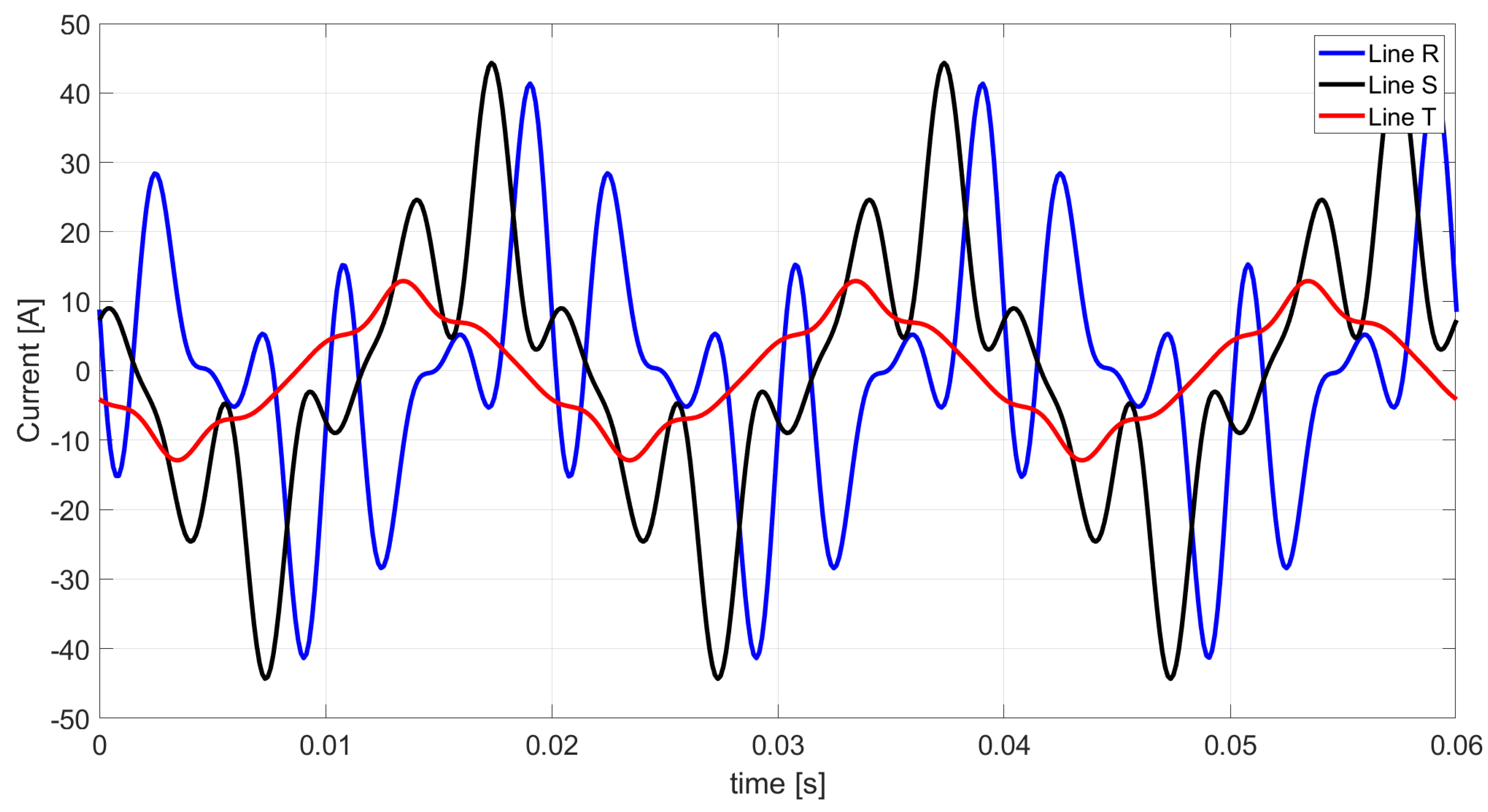
Figure 10.
The line currents waveforms based on Ohm’s law and Kirchhoff’s law after connection of a Budeanu reactive current compensator of the first harmonic.
Figure 10.
The line currents waveforms based on Ohm’s law and Kirchhoff’s law after connection of a Budeanu reactive current compensator of the first harmonic.
Figure 11.
The Budeanu distortion current waveforms following the developed Budeanu theory after compensation of the Budeanu reactive current of the first harmonic.
Figure 11.
The Budeanu distortion current waveforms following the developed Budeanu theory after compensation of the Budeanu reactive current of the first harmonic.
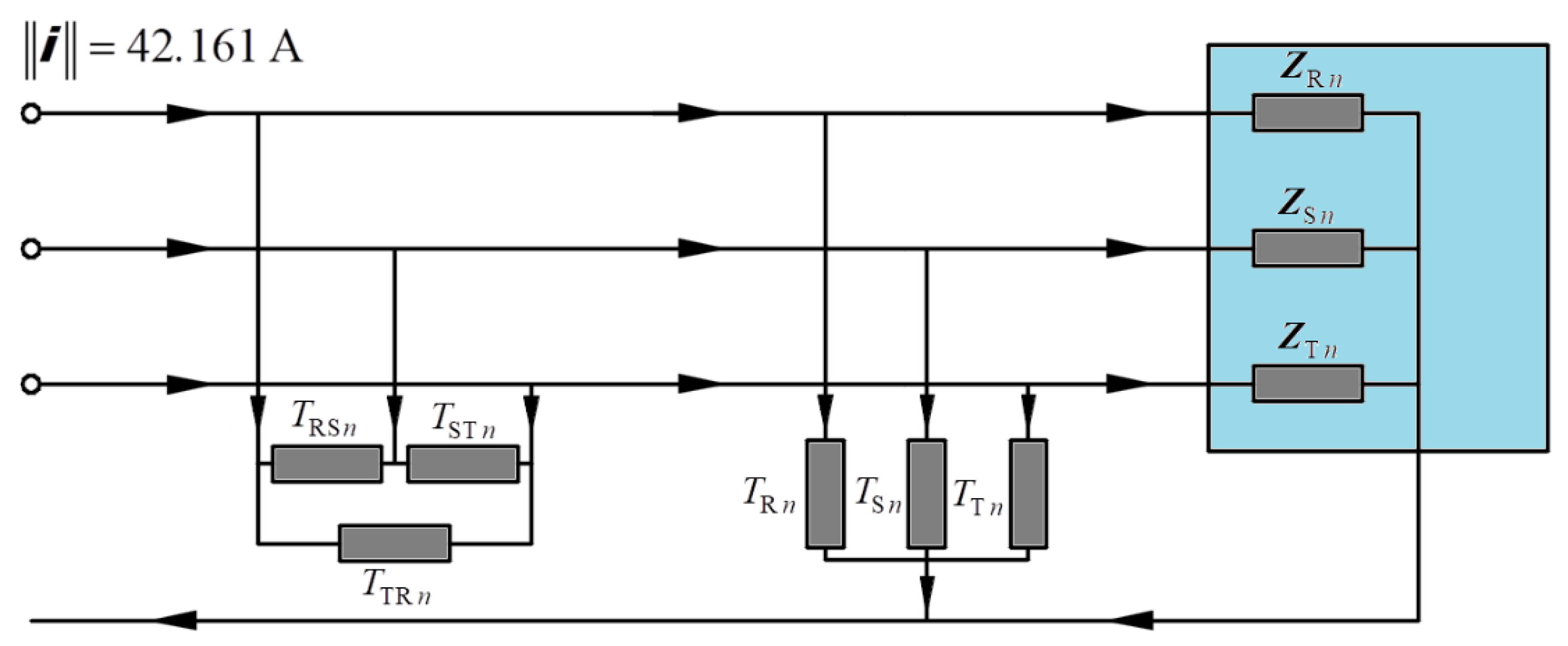
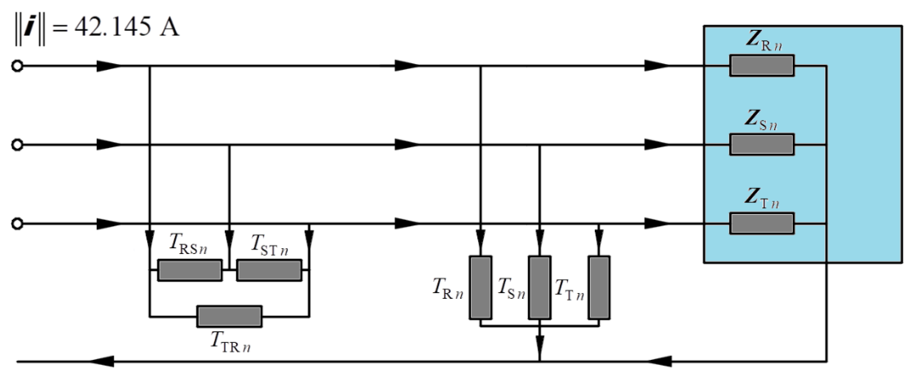
Figure 12.
Original circuit with the connected compensator used to compensate for the Budeanu complemented reactive current and the unbalanced current.
Figure 12.
Original circuit with the connected compensator used to compensate for the Budeanu complemented reactive current and the unbalanced current.
Figure 13.
The waveforms of line currents based on Ohm’s law and Kirchhoff’s law after the connection of a Budeanu complemented reactive current compensator and an unbalanced current.
Figure 13.
The waveforms of line currents based on Ohm’s law and Kirchhoff’s law after the connection of a Budeanu complemented reactive current compensator and an unbalanced current.
Figure 14.
The Budeanu distortion current waveforms following the developed Budeanu theory after reduction in the Budeanu complemented reactive current and the unbalanced current.
Figure 14.
The Budeanu distortion current waveforms following the developed Budeanu theory after reduction in the Budeanu complemented reactive current and the unbalanced current.
Figure 15.
Original circuit with the connected compensator used to compensate for the Budeanu reactive current and the unbalanced current.
Figure 15.
Original circuit with the connected compensator used to compensate for the Budeanu reactive current and the unbalanced current.
Figure 16.
The waveforms of line currents based on Ohm’s law and Kirchhoff’s law after the connection of a Budeanu reactive current compensator and an unbalanced current.
Figure 16.
The waveforms of line currents based on Ohm’s law and Kirchhoff’s law after the connection of a Budeanu reactive current compensator and an unbalanced current.
Figure 17.
The Budeanu distortion current waveforms following the developed Budeanu theory after reduction in the Budeanu reactive current and the unbalanced current.
Figure 17.
The Budeanu distortion current waveforms following the developed Budeanu theory after reduction in the Budeanu reactive current and the unbalanced current.
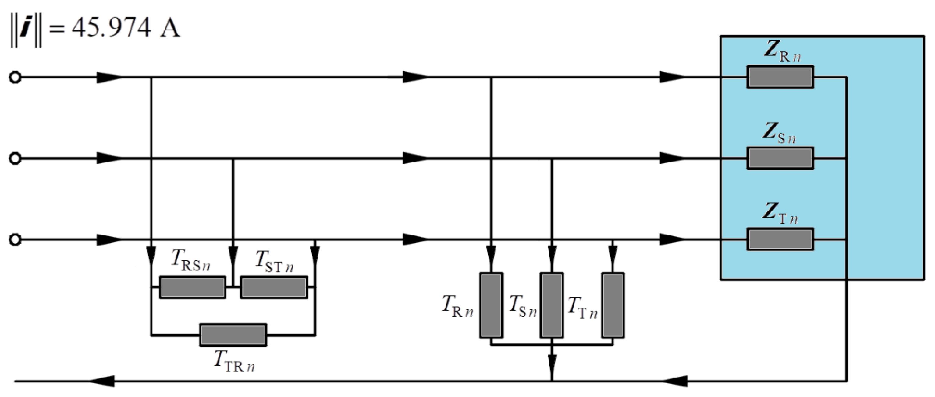
Figure 18.
Original circuit with the connected compensator used to compensate for the Budeanu reactive current, Budeanu complemented reactive current, and the unbalanced current.
Figure 18.
Original circuit with the connected compensator used to compensate for the Budeanu reactive current, Budeanu complemented reactive current, and the unbalanced current.
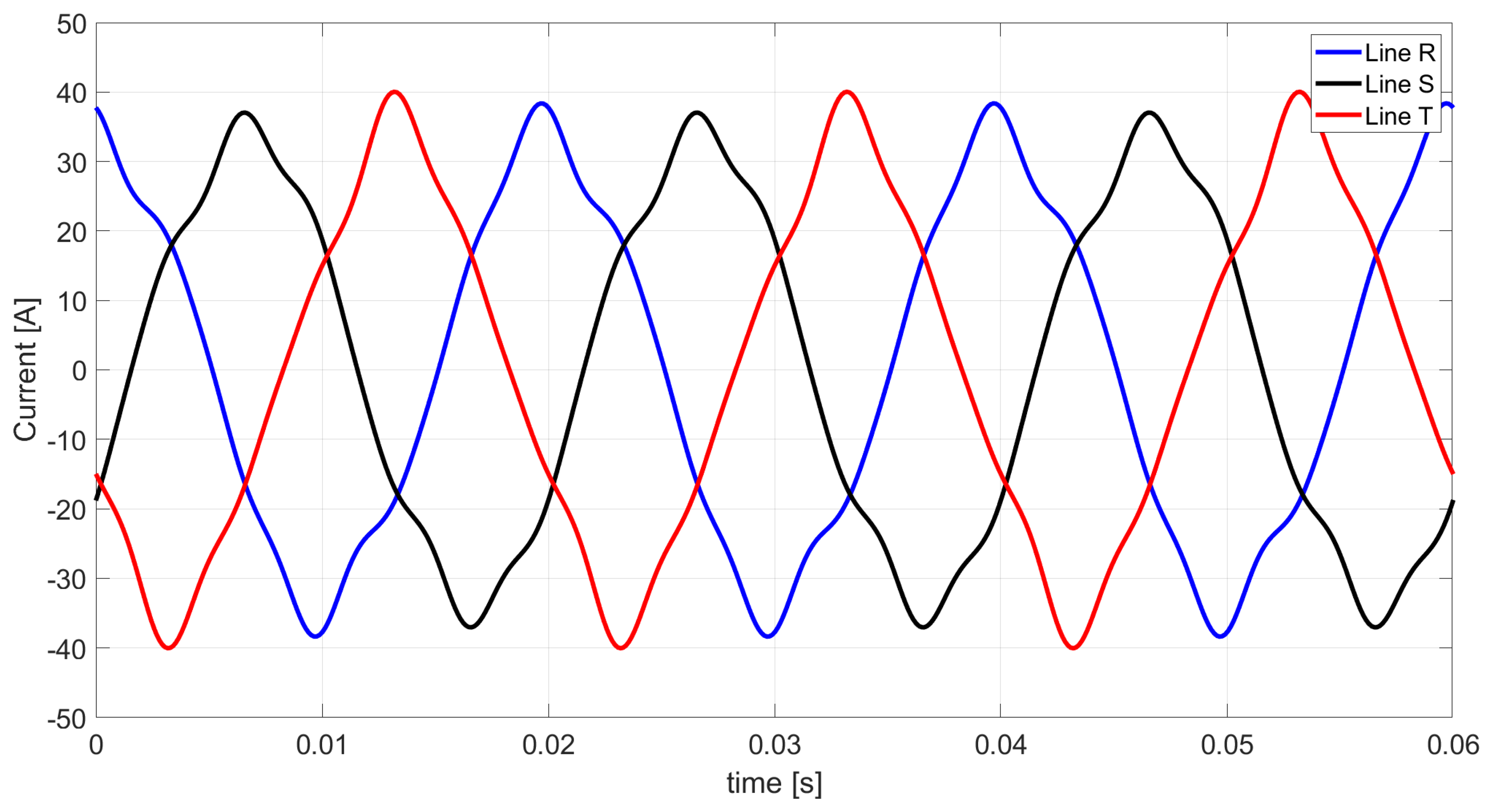
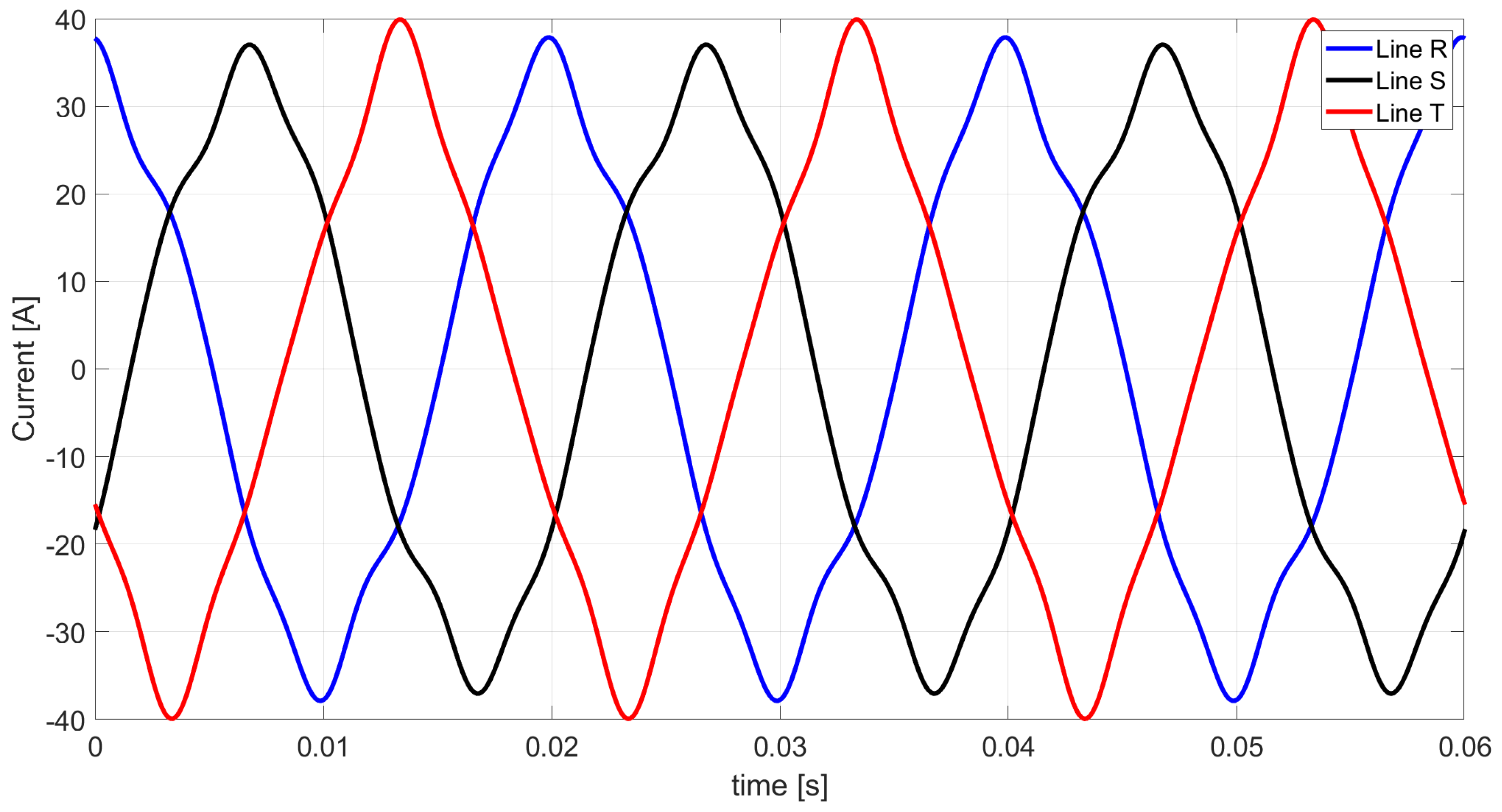
Figure 19.
The waveforms of line currents based on Ohm’s law and Kirchhoff’s law after the connection of a Budeanu reactive current, Budeanu complemented reactive current, and the unbalanced current compensator.
Figure 19.
The waveforms of line currents based on Ohm’s law and Kirchhoff’s law after the connection of a Budeanu reactive current, Budeanu complemented reactive current, and the unbalanced current compensator.
Figure 20.
The Budeanu distortion current waveforms following the developed Budeanu theory after reduction in the Budeanu reactive current, Budeanu complemented reactive current, and the unbalanced current.
Figure 20.
The Budeanu distortion current waveforms following the developed Budeanu theory after reduction in the Budeanu reactive current, Budeanu complemented reactive current, and the unbalanced current.
Table 1.
List of the values of resistance, inductance, and capacitance reactance for the first harmonic.
Table 1.
List of the values of resistance, inductance, and capacitance reactance for the first harmonic.
| Parameter in [Ω] | Line R | Line S | Line T |
|---|
| Resistance | 4.5 | 6 | 7 |
| Inductive reactance | 3.142 | 12.566 | - |
| Capacitive reactance | - | - | 1.592 |
Table 2.
List of complex line currents values for specific harmonics.
Table 2.
List of complex line currents values for specific harmonics.
| Harmonic Order | Line R in [A] | Line S in [A] | Line T in [A] |
|---|
| n = 1 | | | |
| n = 3 | | | |
| n = 5 | | | |
| n = 7 | | | |
Table 3.
List of three-phase values of active and reactive powers for specific harmonics and the total three-phase active and reactive powers of the entire system.
Table 3.
List of three-phase values of active and reactive powers for specific harmonics and the total three-phase active and reactive powers of the entire system.
| Harmonic Order | Active Power P in [W] | Reactive Power QB in [var] |
|---|
| n = 1 | 16,726 | 7312 |
| n = 3 | 42.2 | 22.8 |
| n = 5 | 100.6 | 42.6 |
| n = 7 | 15.2 | 5.0 |
| SUM | 16,884 | 7382.4 |
Table 4.
List of the RMS values of the specific harmonic components for three-phase currents as described by the developed Budeanu theory.
Table 4.
List of the RMS values of the specific harmonic components for three-phase currents as described by the developed Budeanu theory.
| Harmonic Order | ‖ia‖ | ‖is‖ | ‖irB‖ | ‖icrB‖ | ‖‖
| ‖‖
| ‖‖
|
|---|
| n = 1 | 41.635 | 0.351 | 18.205 | 0.150 | 0 | 30.834 | 2.285 |
| n = 3 | 2.715 | 1.092 | 1.187 | 0.308 | 1.717 | 0.653 | 0 |
| n = 5 | 4.256 | 2.203 | 1.979 | 0.996 | 1.455 | 0 | 2.598 |
| n = 7 | 1.810 | 0.930 | 0.792 | 0.501 | 0 | 0.984 | 0.651 |
| RMS | 42.007 | 2.652 | 18.368 | 1.166 | 2.251 | 30.856 | 3.521 |
Table 5.
List of three-phase RMS currents’ components values of the distortion current described in the Budeanu theory.
Table 5.
List of three-phase RMS currents’ components values of the distortion current described in the Budeanu theory.
| Harmonic Order | ‖is‖ | ‖icrB‖ | ‖‖
| ‖‖
| ‖‖
| ‖idB‖ |
|---|
| n = 1 | 0.351 | 0.150 | 0 | 30.834 | 2.285 | |
| n = 3 | 1.092 | 0.308 | 1.717 | 0.653 | 0 |
| n = 5 | 2.203 | 0.996 | 1.455 | 0 | 2.598 |
| n = 7 | 0.930 | 0.501 | 0 | 0.984 | 0.651 |
| RMS | 2.652 | 1.166 | 2.251 | 30.856 | 3.521 | 31.273 |
Table 6.
List of values of inductance and capacitance required to compensate for the first harmonic of reactive current.
Table 6.
List of values of inductance and capacitance required to compensate for the first harmonic of reactive current.
| Parameter | Line R | Line S | Line T |
|---|
| Inductance [mH] | - | - | 103.07 |
| Capacitance [mF] | 33.20 | 20.63 | - |
Table 7.
List of values of the complex line currents for the respective harmonics after reduction in the reactive current of the first harmonic.
Table 7.
List of values of the complex line currents for the respective harmonics after reduction in the reactive current of the first harmonic.
| Harmonic Order | Line R in [A] | Line S in [A] | Line T in [A] |
|---|
| n = 1 | | | |
| n = 3 | | | |
| n = 5 | | | |
| n = 7 | | | |
Table 8.
List of the active and reactive powers for specific harmonics in three phases, along with the total active and reactive powers of the entire circuit after reactive current reduction for the first harmonic.
Table 8.
List of the active and reactive powers for specific harmonics in three phases, along with the total active and reactive powers of the entire circuit after reactive current reduction for the first harmonic.
| Harmonic Order | Active Power P in [W] | Reactive Power QB in [var] |
|---|
| n = 1 | 16,726 | 0 |
| n = 3 | 42.2 | −89 |
| n = 5 | 100.6 | −482 |
| n = 7 | 15.2 | −112.9 |
| SUM | 16,884 | −683.9 |
Table 9.
List of three-phase RMS current’s components values corresponding to specific harmonics, as provided in the developed Budeanu theory, following reduction in the reactive current of the first harmonic.
Table 9.
List of three-phase RMS current’s components values corresponding to specific harmonics, as provided in the developed Budeanu theory, following reduction in the reactive current of the first harmonic.
| Harmonic Order | ‖ia‖ | ‖is‖ | ‖irB‖ | ‖icrB‖ | ‖‖ | ‖‖ | ‖‖ |
|---|
| n = 1 | 41.635 | 0.351 | 1.687 | 1.687 | 0 | 14.912 | 14.912 |
| n = 3 | 2.715 | 1.092 | 0.110 | 3.315 | 1.549 | 2.469 | 0 |
| n = 5 | 4.256 | 2.203 | 0.183 | 10.949 | 6.924 | 0 | 5.368 |
| n = 7 | 1.810 | 0.930 | 0.073 | 6.445 | 0 | 3.244 | 3.866 |
| RMS | 42.007 | 2.652 | 1.702 | 13.238 | 7.095 | 15.459 | 16.313 |
Table 10.
List of three-phase RMS currents’ components values of the distortion current described in the Budeanu theory.
Table 10.
List of three-phase RMS currents’ components values of the distortion current described in the Budeanu theory.
| Harmonic Order | ‖is‖ | ‖icrB‖ | ‖‖
| ‖‖
| ‖‖
| ‖idB‖ |
|---|
| n = 1 | 0.351 | 1.687 | 0 | 14.912 | 14.912 | |
| n = 3 | 1.092 | 3.315 | 1.549 | 2.469 | 0 |
| n = 5 | 2.203 | 10.949 | 6.924 | 0 | 5.368 |
| n = 7 | 0.930 | 6.445 | 0 | 3.244 | 3.866 |
| RMS | 2.652 | 13.238 | 7.095 | 15.459 | 16.313 | 27.161 |
Table 11.
List of equivalent susceptance values necessary to compensate for the first harmonic of the Budeanu reactive current.
Table 11.
List of equivalent susceptance values necessary to compensate for the first harmonic of the Budeanu reactive current.
| Parameter | Line R | Line S | Line T |
|---|
| Capacitance [mF] | 14.55 | 14.55 | 14.55 |
Table 12.
List of complex line currents values for respective harmonics after reduction in the Budeanu reactive current of the first harmonic.
Table 12.
List of complex line currents values for respective harmonics after reduction in the Budeanu reactive current of the first harmonic.
| Harmonic Order | Line R in [A] | Line S in [A] | Line T in [A] |
|---|
| n = 1 | | | |
| n = 3 | | | |
| n = 5 | | | |
| n = 7 | | | |
Table 13.
List of three-phase active power and reactive power values of chosen harmonics and total three-phase active power and reactive power of the whole system after reduction in the Budeanu reactive current of the first harmonic.
Table 13.
List of three-phase active power and reactive power values of chosen harmonics and total three-phase active power and reactive power of the whole system after reduction in the Budeanu reactive current of the first harmonic.
| Harmonic Order | Active Power P in [W] | Reactive Power QB in [var] |
|---|
| n = 1 | 16,726 | 59.8 |
| n = 3 | 42.2 | −69.7 |
| n = 5 | 100.6 | −385.8 |
| n = 7 | 15.2 | −90.9 |
| SUM | 16,884 | −486.7 |
Table 14.
List of three-phase RMS currents’ components values for the chosen harmonics defined in the developed Budeanu theory after reduction in the Budeanu reactive current of the first harmonic.
Table 14.
List of three-phase RMS currents’ components values for the chosen harmonics defined in the developed Budeanu theory after reduction in the Budeanu reactive current of the first harmonic.
| Harmonic Order | ‖ia‖ | ‖is‖ | ‖irB‖ | ‖icrB‖ | ‖‖ | ‖‖ | ‖‖ |
|---|
| n = 1 | 41.635 | 0.351 | 1.200 | 1.350 | 0 | 30.834 | 2.285 |
| n = 3 | 2.715 | 1.092 | 0.078 | 2.604 | 1.717 | 0.653 | 0 |
| n = 5 | 4.256 | 2.203 | 0.130 | 8.780 | 1.455 | 0 | 2.598 |
| n = 7 | 1.810 | 0.930 | 0.052 | 5.198 | 0 | 0.984 | 0.651 |
| RMS | 42.007 | 2.652 | 1.211 | 10.617 | 2.251 | 30.856 | 3.521 |
Table 15.
List of three-phase RMS currents’ components values of the distortion current defined in the Budeanu theory.
Table 15.
List of three-phase RMS currents’ components values of the distortion current defined in the Budeanu theory.
| Harmonic Order | ‖is‖ | ‖icrB‖ | ‖‖ | ‖‖ | ‖‖ | ‖idB‖ |
|---|
| n = 1 | 0.351 | 1.350 | 0 | 30.834 | 2.285 | |
| n = 3 | 1.092 | 2.604 | 1.717 | 0.653 | 0 |
| n = 5 | 2.203 | 8.780 | 1.455 | 0 | 2.598 |
| n = 7 | 0.930 | 5.198 | 0 | 0.984 | 0.651 |
| RMS | 2.652 | 10.617 | 2.251 | 30.856 | 3.521 | 33.005 |
Table 16.
List of capacitance and inductance values necessary to compensate for the Budeanu complemented reactive current and the unbalanced current for a compensator with a Y-structure.
Table 16.
List of capacitance and inductance values necessary to compensate for the Budeanu complemented reactive current and the unbalanced current for a compensator with a Y-structure.
| Line | Harmonic Order |
|---|
| n = 1 | n = 3 | n = 5 | n = 7 |
|---|
| C [µF] | L [µH] | C [µF] | L [mH] | C [µF] | L [mH] | C [µF] | L [mH] |
|---|
| R | - | 6.22 | 127.68 | - | 60.21 | - | - | 5.41 |
| S | 35.88 | - | - | 13.60 | - | 6.21 | 19.49 | - |
| T | - | 26.06 | - | 13.62 | - | 10.43 | - | 9.97 |
Table 17.
List of capacitance and inductance values necessary to compensate for the component of the unbalanced current for a -structure compensator.
Table 17.
List of capacitance and inductance values necessary to compensate for the component of the unbalanced current for a -structure compensator.
| Line | Harmonic Order |
|---|
| n = 1 | n = 3 | n = 5 | n = 7 |
|---|
| C [µF] | L [µH] | C [µF] | L [mH] | C [µF] | L [mH] | C [µF] | L [mH] |
|---|
| RS | 145.14 | - | - | - | - | 107.76 | 1.43 | - |
| ST | - | 128.51 | - | - | 34.64 | - | - | 8.32 |
| TR | - | 16.63 | - | - | - | 13.16 | 23.41 | - |
Table 18.
List of complex values of line currents for specific harmonics after reduction in the Budeanu complemented reactive current and the unbalanced current.
Table 18.
List of complex values of line currents for specific harmonics after reduction in the Budeanu complemented reactive current and the unbalanced current.
| Harmonic Order | Line R in [A] | Line S in [A] | Line T in [A] |
|---|
| n = 1 | | | |
| n = 3 | | | |
| n = 5 | | | |
| n = 7 | | | |
Table 19.
List of the active and reactive powers for specific harmonics in three phases, along with the total active and reactive powers of the entire circuit after compensating for the Budeanu complemented reactive current and the unbalanced current.
Table 19.
List of the active and reactive powers for specific harmonics in three phases, along with the total active and reactive powers of the entire circuit after compensating for the Budeanu complemented reactive current and the unbalanced current.
| Harmonic Order | Active Power P in [W] | Reactive Power QB in [var] |
|---|
| n = 1 | 16,726 | 7252.2 |
| n = 3 | 42.2 | 30.8 |
| n = 5 | 100.6 | 85.7 |
| n = 7 | 15.2 | 13.7 |
| SUM | 16,884 | 7382.4 |
Table 20.
List of three-phase RMS currents’ components values for the chosen harmonics defined in the developed Budeanu theory after reduction in the Budeanu complemented reactive current and the unbalanced current.
Table 20.
List of three-phase RMS currents’ components values for the chosen harmonics defined in the developed Budeanu theory after reduction in the Budeanu complemented reactive current and the unbalanced current.
| Harmonic Order | ‖ia‖ | ‖is‖ | ‖irB‖ | ‖icrB‖ | ‖‖
| ‖‖
| ‖‖
|
|---|
| n = 1 | 41.635 | 0.351 | 18.205 | 0 | 0 | 0 | 0 |
| n = 3 | 2.715 | 1.092 | 1.187 | 0 | 0 | 2.141 | 0 |
| n = 5 | 4.256 | 2.203 | 1.979 | 0 | 0 | 0 | 0 |
| n = 7 | 1.810 | 0.930 | 0.792 | 0 | 0 | 0 | 0 |
| RMS | 42.007 | 2.652 | 18.368 | 0 | 0 | 2.141 | 0 |
Table 21.
List of the three-phase RMS values of the currents’ components of the distortion current defined in the Budeanu theory.
Table 21.
List of the three-phase RMS values of the currents’ components of the distortion current defined in the Budeanu theory.
| Harmonic Order | ‖is‖ | ‖icrB‖ | ‖‖
| ‖‖
| ‖‖
| ‖idB‖ |
|---|
| n = 1 | 0.351 | 0 | 0 | 0 | 0 | |
| n = 3 | 1.092 | 0 | 0 | 2.141 | 0 |
| n = 5 | 2.203 | 0 | 0 | 0 | 0 |
| n = 7 | 0.930 | 0 | 0 | 0 | 0 |
| RMS | 2.652 | 0 | 0 | 2.141 | 0 | 3.409 |
Table 22.
List of capacitance and inductance values necessary to compensate for the Budeanu reactive current and the unbalanced current for a compensator with a Y-structure.
Table 22.
List of capacitance and inductance values necessary to compensate for the Budeanu reactive current and the unbalanced current for a compensator with a Y-structure.
| Line | Harmonic Order |
|---|
| n = 1 | n = 3 | n = 5 | n = 7 |
|---|
| C [µF] | L [µH] | C [µF] | L [mH] | C [µF] | L [mH] | C [µF] | L [mH] |
|---|
| R | 138.04 | - | 188.75 | - | 103.94 | - | - | 48.49 |
| S | 180.14 | - | - | 51.87 | - | 18.83 | 53.42 | - |
| T | 118.20 | - | - | 52.15 | 4.87 | - | 13.19 | - |
Table 23.
List of capacitance and inductance values necessary to compensate for the component of the unbalanced current for a -structure compensator.
Table 23.
List of capacitance and inductance values necessary to compensate for the component of the unbalanced current for a -structure compensator.
| Line | Harmonic Order |
|---|
| n = 1 | n = 3 | n = 5 | n = 7 |
|---|
| C [µF] | L [µH] | C [µF] | L [mH] | C [µF] | L [mH] | C [µF] | L [mH] |
|---|
| RS | 145.14 | - | - | - | - | 107.76 | 1.43 | - |
| ST | - | 78.84 | - | - | 34.56 | - | - | 8.32 |
| TR | - | 609.47 | - | - | - | 13.16 | 23.41 | - |
Table 24.
List of complex values of line currents for respective harmonics after reduction in the Budeanu reactive current and the unbalanced current.
Table 24.
List of complex values of line currents for respective harmonics after reduction in the Budeanu reactive current and the unbalanced current.
| Harmonic Order | Line R in [A] | Line S in [A] | Line T in [A] |
|---|
| n = 1 | | | |
| n = 3 | | | |
| n = 5 | | | |
| n = 7 | | | |
Table 25.
List detailing the three-phase active and reactive powers of specific harmonics, as well as the total three-phase active and reactive powers of the entire circuit following compensation for both the Budeanu reactive current and the unbalanced current.
Table 25.
List detailing the three-phase active and reactive powers of specific harmonics, as well as the total three-phase active and reactive powers of the entire circuit following compensation for both the Budeanu reactive current and the unbalanced current.
| Harmonic Order | Active Power P in [W] | Reactive Power QB in [var] |
|---|
| n = 1 | 16,726 | 59.8 |
| n = 3 | 42.2 | −8 |
| n = 5 | 100.6 | −43.1 |
| n = 7 | 15.2 | −8.7 |
| SUM | 16,884 | 0 |
Table 26.
List of three-phase RMS currents’ components values for the respective harmonics defined in the developed Budeanu theory after reduction in the Budeanu reactive current and the unbalanced current.
Table 26.
List of three-phase RMS currents’ components values for the respective harmonics defined in the developed Budeanu theory after reduction in the Budeanu reactive current and the unbalanced current.
| Harmonic Order | ‖ia‖ | ‖is‖ | ‖irB‖ | ‖icrB‖ | ‖‖
| ‖‖
| ‖‖
|
|---|
| n = 1 | 41.635 | 0.351 | 0 | 0.150 | 0 | 0 | 0 |
| n = 3 | 2.715 | 1.092 | 0 | 0.308 | 0 | 2.141 | 0 |
| n = 5 | 4.256 | 2.203 | 0 | 0.996 | 0 | 0 | 0 |
| n = 7 | 1.810 | 0.930 | 0 | 0.501 | 0 | 0 | 0 |
| RMS | 42.007 | 2.652 | 0 | 1.166 | 0 | 2.141 | 0 |
Table 27.
List of the three-phase RMS currents’ components values of the distortion current described in the Budeanu theory.
Table 27.
List of the three-phase RMS currents’ components values of the distortion current described in the Budeanu theory.
| Harmonic Order | ‖is‖ | ‖icrB‖ | ‖‖
| ‖‖
| ‖‖
| ‖idB‖ |
|---|
| n = 1 | 0.351 | 0.150 | 0 | 0 | 0 | |
| n = 3 | 1.092 | 0.308 | 0 | 2.141 | 0 |
| n = 5 | 2.203 | 0.996 | 0 | 0 | 0 |
| n = 7 | 0.930 | 0.501 | 0 | 0 | 0 |
| RMS | 2.652 | 1.166 | 0 | 2.141 | 0 | 3.602 |
Table 28.
List of capacitance and inductance values necessary to compensate for the Budeanu reactive current, Budeanu complemented reactive current, and the unbalanced current for a compensator with a Y-structure.
Table 28.
List of capacitance and inductance values necessary to compensate for the Budeanu reactive current, Budeanu complemented reactive current, and the unbalanced current for a compensator with a Y-structure.
| Line | Harmonic Order |
|---|
| n = 1 | n = 3 | n = 5 | n = 7 |
|---|
| C [µF] | L [µH] | C [µF] | L [mH] | C [µF] | L [mH] | C [µF] | L [mH] |
|---|
| R | 139.24 | - | 176.17 | - | 89.30 | - | - | 11.87 |
| S | 181.34 | - | - | 15.38 | - | 11.21 | 40.27 | - |
| T | 119.40 | - | 4.76 | - | - | 41.49 | 0.034 | - |
Table 29.
List of capacitance and inductance values necessary to compensate for the component of the unbalanced current for a -structure compensator.
Table 29.
List of capacitance and inductance values necessary to compensate for the component of the unbalanced current for a -structure compensator.
| Line | Harmonic Order |
|---|
| n = 1 | n = 3 | n = 5 | n = 7 |
|---|
| C [µF] | L [µH] | C [µF] | L [mH] | C [µF] | L [mH] | C [µF] | L [mH] |
|---|
| RS | 145.14 | - | - | - | - | 107.76 | 1.43 | - |
| ST | - | 78.84 | - | - | 34.56 | - | - | 8.32 |
| TR | - | 609.47 | - | - | - | 13.16 | 23.41 | - |
Table 30.
List of complex line currents values for chosen harmonics after reduction in the Budeanu reactive current, Budeanu complemented reactive current, and the unbalanced current.
Table 30.
List of complex line currents values for chosen harmonics after reduction in the Budeanu reactive current, Budeanu complemented reactive current, and the unbalanced current.
| Harmonic Order | Line R in [A] | Line S in [A] | Line T in [A] |
|---|
| n = 1 | | | |
| n = 3 | | | |
| n = 5 | | | |
| n = 7 | | | |
Table 31.
List of three-phase RMS currents’ components values for the chosen harmonics defined in the developed Budeanu theory after reduction in the Budeanu reactive current, Budeanu complemented reactive current, and the unbalanced current.
Table 31.
List of three-phase RMS currents’ components values for the chosen harmonics defined in the developed Budeanu theory after reduction in the Budeanu reactive current, Budeanu complemented reactive current, and the unbalanced current.
| Harmonic Order | Active Power P in [W] | Reactive Power QB in [var] |
|---|
| n = 1 | 16,726 | 0 |
| n = 3 | 42.2 | 0 |
| n = 5 | 100.6 | 0 |
| n = 7 | 15.2 | 0 |
| SUM | 16,884 | 0 |
Table 32.
List of three-phase RMS currents’ components values for the respective harmonics defined in the developed Budeanu theory after reduction in the Budeanu reactive current, Budeanu complemented reactive current, and the unbalanced current.
Table 32.
List of three-phase RMS currents’ components values for the respective harmonics defined in the developed Budeanu theory after reduction in the Budeanu reactive current, Budeanu complemented reactive current, and the unbalanced current.
| Harmonic Order | ‖ia‖ | ‖is‖ | ‖irB‖ | ‖icrB‖ | ‖‖
| ‖‖
| ‖‖
|
|---|
| n = 1 | 41.635 | 0.351 | 0 | 0 | 0 | 0 | 0 |
| n = 3 | 2.715 | 1.092 | 0 | 0 | 0 | 2.141 | 0 |
| n = 5 | 4.256 | 2.203 | 0 | 0 | 0 | 0 | 0 |
| n = 7 | 1.810 | 0.930 | 0 | 0 | 0 | 0 | 0 |
| RMS | 42.007 | 2.652 | 0 | 0 | 0 | 2.141 | 0 |
Table 33.
List of the three-phase RMS currents’ components values of the distortion current determined in the Budeanu theory.
Table 33.
List of the three-phase RMS currents’ components values of the distortion current determined in the Budeanu theory.
| Harmonic Order | ‖is‖ | ‖icrB‖ | ‖‖
| ‖‖
| ‖‖
| ‖idB‖ |
|---|
| n = 1 | 0.351 | 0 | 0 | 0 | 0 | |
| n = 3 | 1.092 | 0 | 0 | 2.141 | 0 |
| n = 5 | 2.203 | 0 | 0 | 0 | 0 |
| n = 7 | 0.930 | 0 | 0 | 0 | 0 |
| RMS | 2.652 | 0 | 0 | 2.141 | 0 | 3.409 |
Table 34.
List of three-phase RMS currents’ components values for the original circuit and the systems after the connection of the compensator.
Table 34.
List of three-phase RMS currents’ components values for the original circuit and the systems after the connection of the compensator.
| Component | Original System | Method |
|---|
| I | II | III | IV | V |
|---|
| 42.007 | 42.007 | 42.007 | 42.007 | 42.007 | 42.007 |
| 2.652 | 2.652 | 2.652 | 2.652 | 2.652 | 2.652 |
| 18.368 | 1.702 | 1.211 | 18.368 | 0 | 0 |
| 1.166 | 13.238 | 10.617 | 0 | 1.166 | 0 |
| 2.251 | 7.095 | 2.251 | 0 | 0 | 0 |
| 30.856 | 15.459 | 30.856 | 2.141 | 2.141 | 2.141 |
| 3.521 | 16.313 | 3.521 | 0 | 0 | 0 |
| 31.273 | 27.161 | 33.005 | 3.409 | 3.602 | 3.409 |
| 55.497 | 50.052 | 53.436 | 45.974 | 42.161 | 42.145 |
Table 35.
List of percentages of absolute values of currents’ components for the original circuit and the systems after the connection of the compensator.
Table 35.
List of percentages of absolute values of currents’ components for the original circuit and the systems after the connection of the compensator.
| Component | Original System | Method |
|---|
| I | II | III | IV | V |
|---|
| - | - | - | - | - | - |
| - | - | - | - | - | - |
| - | −979% | −1417% | 0% | z | z |
| - | 91% | 89% | z | 0% | z |
| - | 68% | 0% | z | z | z |
| - | −100% | 0% | −1341% | −1341% | −1341% |
| - | 78% | 0% | z | z | z |
| - | −15% | 5% | −817% | −768% | −817% |
| - | −11% | −4% | −21% | −32% | −32% |
Table 36.
List of three-phase powers’ components values calculated based on the Budeanu theory for the original circuit and the systems after the connection of the compensator.
Table 36.
List of three-phase powers’ components values calculated based on the Budeanu theory for the original circuit and the systems after the connection of the compensator.
| Power | Original System | Method |
|---|
| I | II | III | IV | V |
|---|
| S [VA] | 22,306.1 | 20,117.5 | 21,477.6 | 18,478.3 | 16,945.9 | 16,939.5 |
| P [W] | 16,884 | 16,884 | 16,884 | 16,884 | 16,884 | 16,884 |
| QB [var] | 7382.4 | −683.9 | −486.7 | 7382.4 | 0 | 0 |
| DB [VA] | 12,569.5 | 10,916.9 | 13,265.8 | 1370 | 1447.9 | 1370 |
Table 37.
List of percentages of the absolute values of the powers’ components calculated based on the Budeanu theory for the original circuit and the systems after the connection of the compensator.
Table 37.
List of percentages of the absolute values of the powers’ components calculated based on the Budeanu theory for the original circuit and the systems after the connection of the compensator.
| Power | Original System | Method |
|---|
| I | II | III | IV | V |
|---|
| S [VA] | - | −11% | −4% | −21% | −32% | −32% |
| P [W] | - | - | - | - | - | - |
| QB [var] | - | 1179% | 1617% | 0% | z | z |
| DB [VA] | - | −15% | 5% | −817% | −768% | −817% |


