
A Review of Thermal Energy Management of Diesel Exhaust after-Treatment Systems Technology and Efficiency Enhancement Approaches


Abstract
1. Introduction
2. Composition and Work Principle of Diesel Engine after-Treatment Systems
2.1. DOC
2.2. DPF
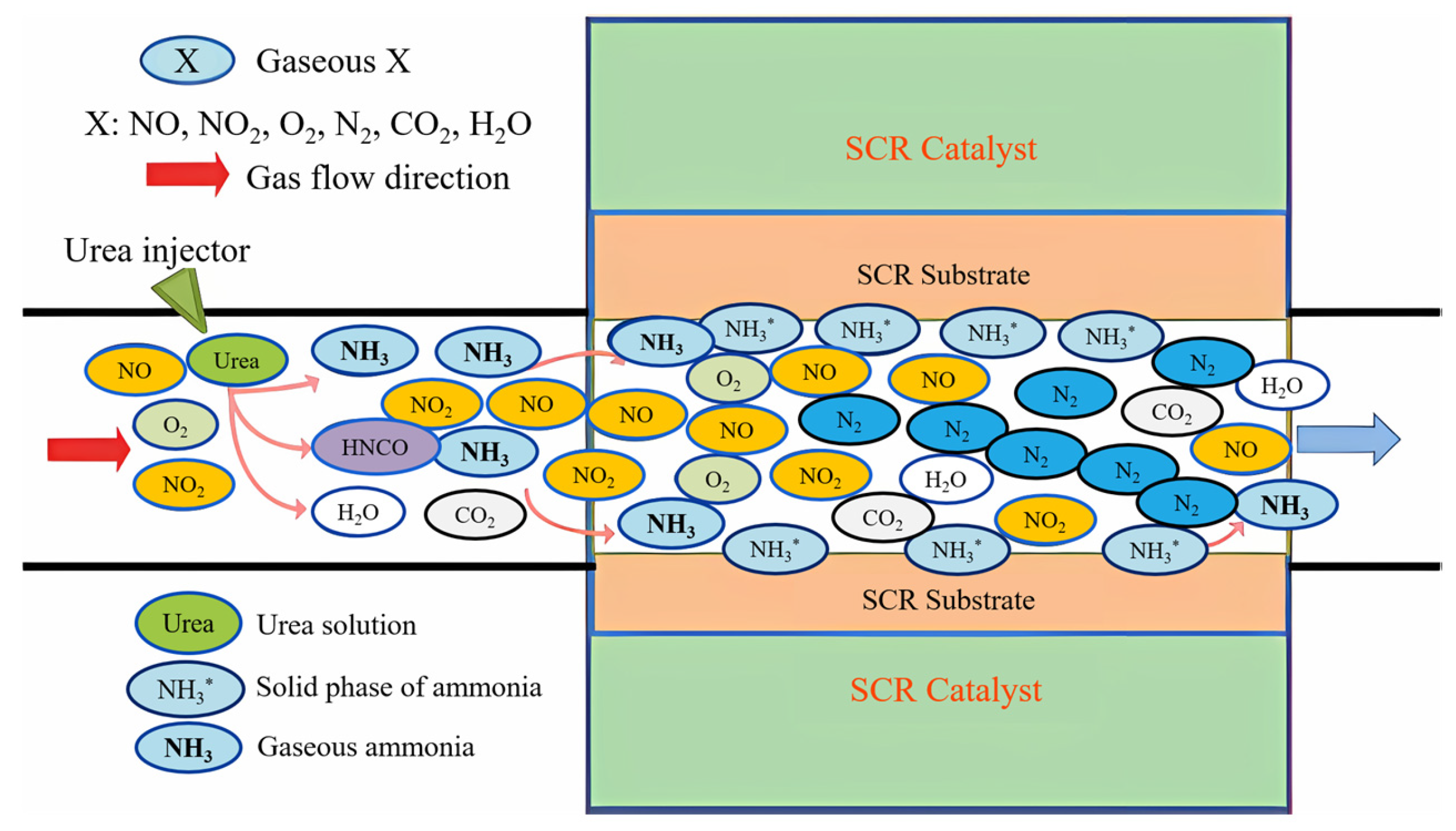
2.3. SCR and ASC
3. After-Treatment Thermal Management Technology
3.1. Exhaust Gas Thermal Management
3.2. DOC Thermal Management
3.3. DPF Thermal Management
3.4. SCR Thermal Management
4. After-Treatment Systems Efficiency Enhancement Approaches
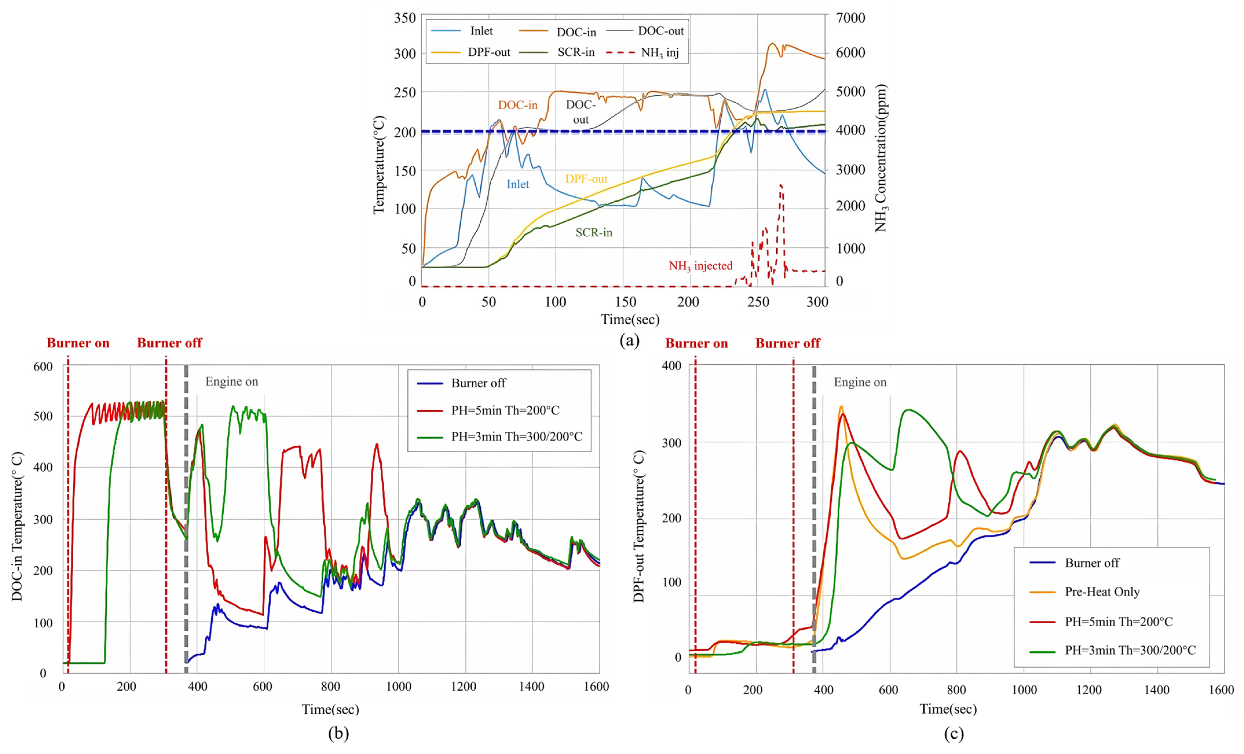
4.1. Burner
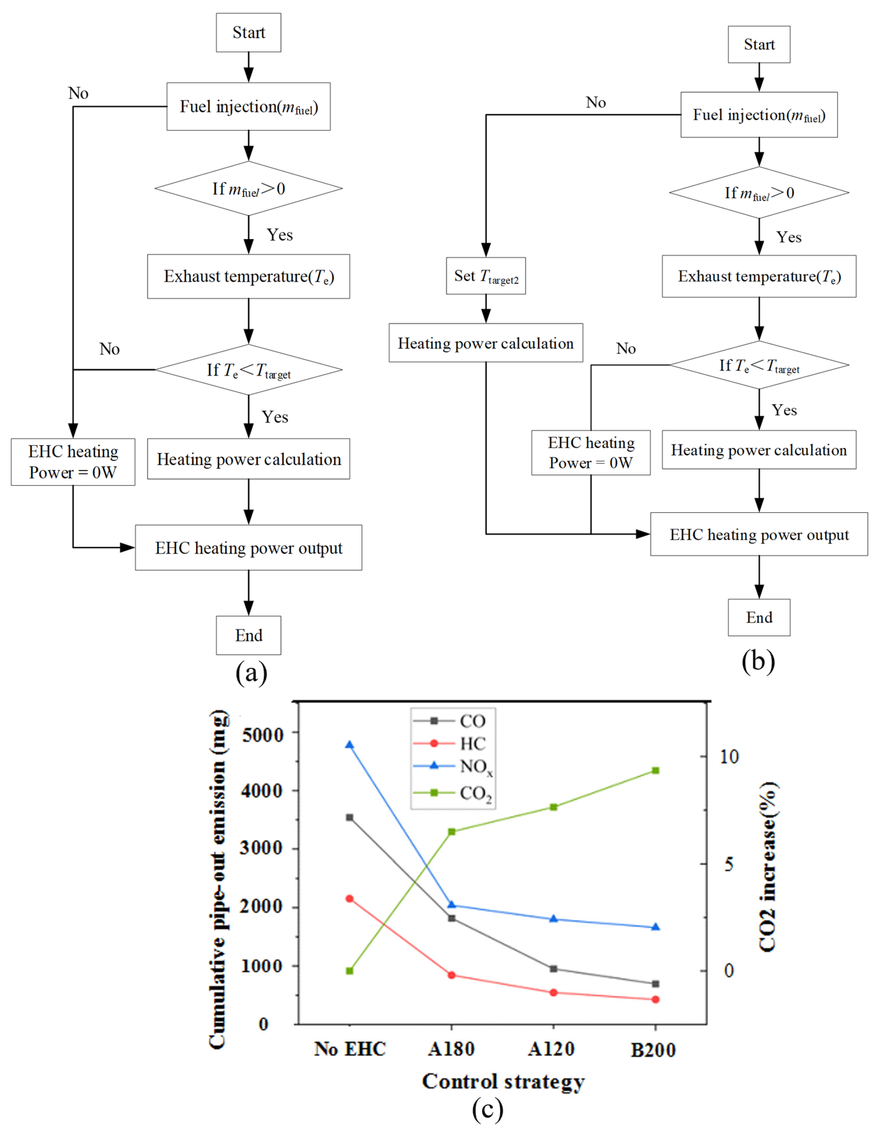
4.2. EHC
4.3. Thermal Insulation
4.4. PCMs and the Heat Recovery System

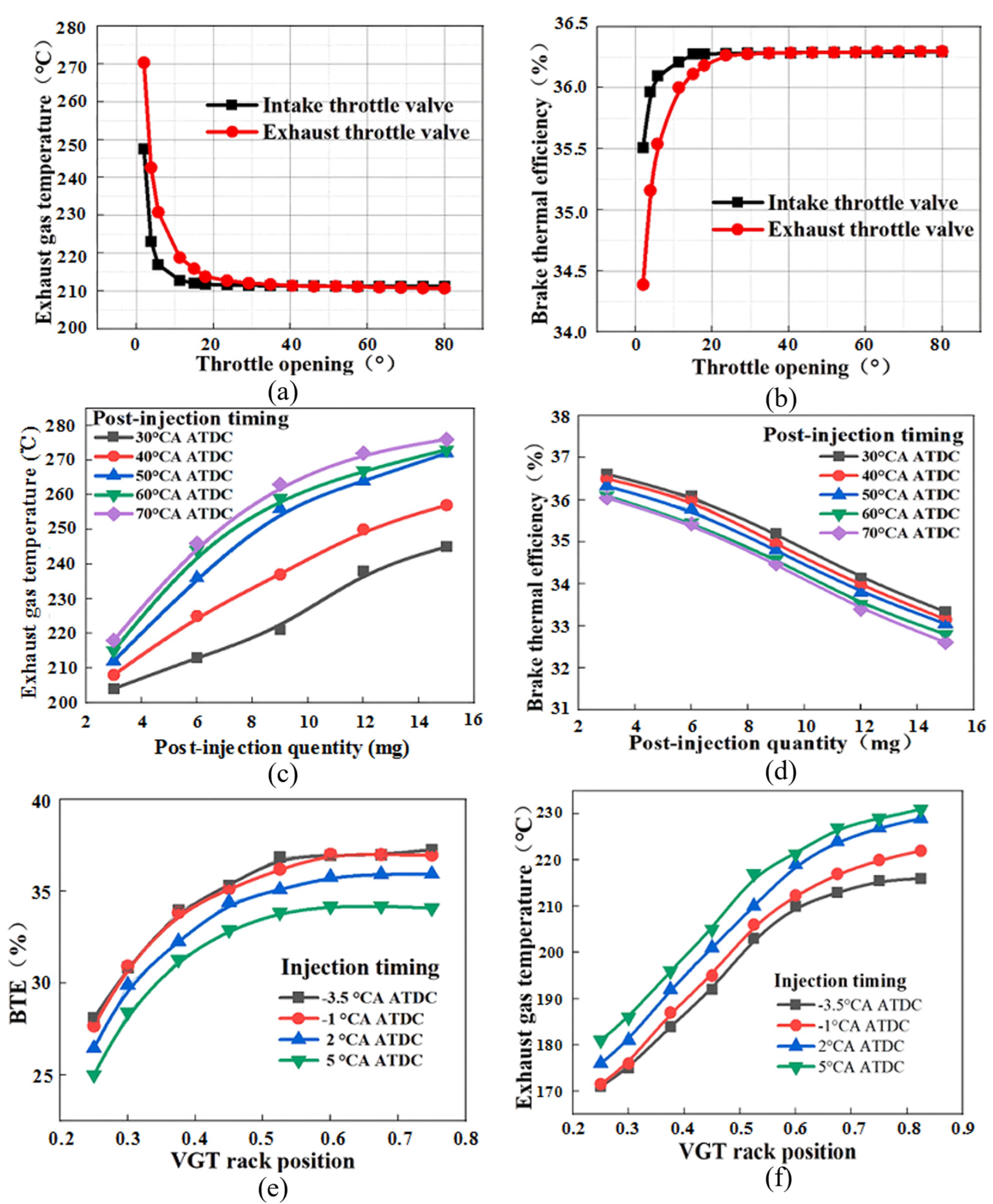
4.5. VVT and Post Injection
4.6. Catalysts
5. Outlook for Future Research
5.1. Shortcomings of Current Technologies
5.2. Outlook for Future Technologies
- (1)
- To optimize CO2 emissions and exhaust temperatures, control strategies for the EHC and post injection coupled methods are investigated [137].
- (2)
- (3)
- (4)
- (5)
6. Conclusions
- (1)
- SCR burners can decrease NOx emissions by 93.5%. EHC can decrease CO, HC, and NOx emissions by 80%, 80%, and 66%, respectively. PCMs can control the temperature of SCR, resulting in a 2/3 reduction in NOx emissions.
- (2)
- Thermal insulation decreases the heat loss of the exhaust gas, which can reduce the after-treatment light-off time. DOC light-off time was reduced by 75% under adiabatic conditions. Microwave is an effective method for DPF regeneration. A 400 W microwave can heat the DPF to the soot oxidation temperature of 873 K at a regeneration time of 150 s.
- (3)
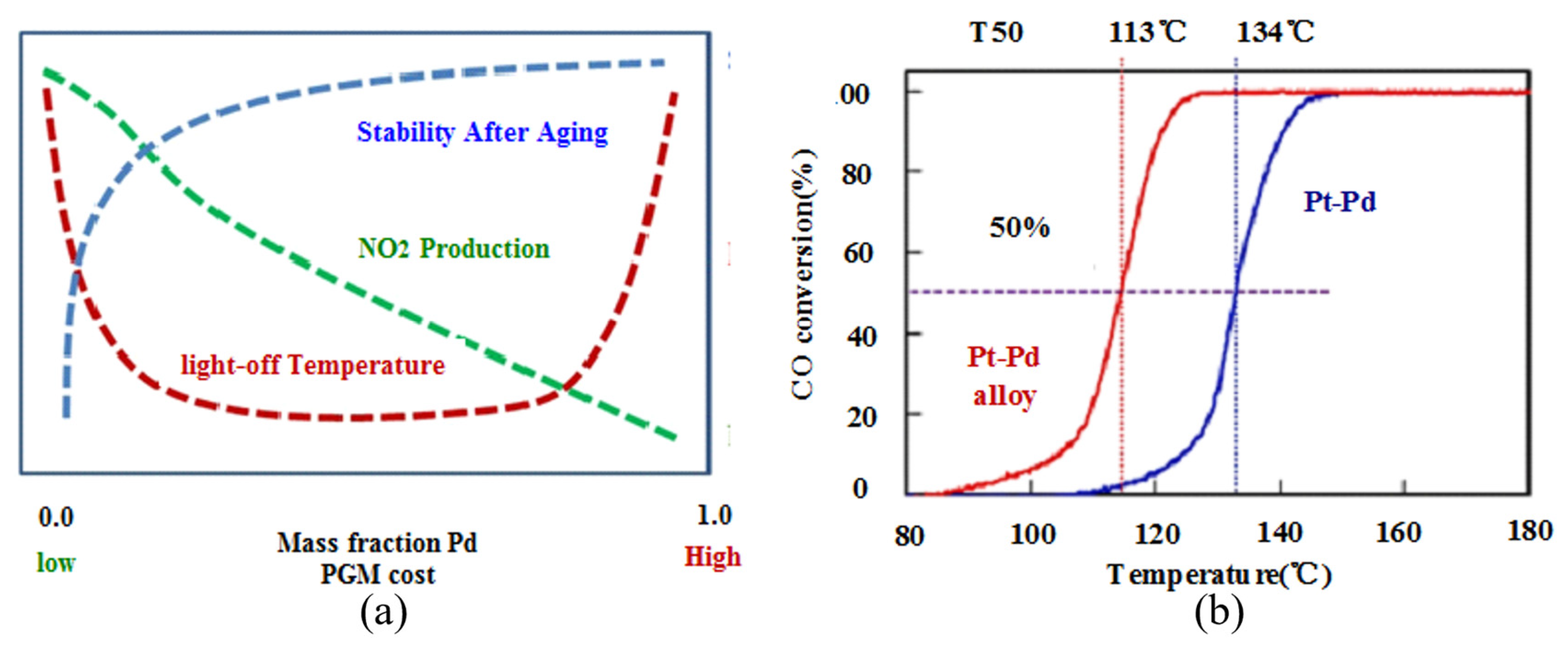
- Catalysts can enhance the efficiency of the after-treatment system and reduce the thermal management energy consumption. Pt-Pd application in the catalyst can decrease the CO light-off temperature to 113 °C. The LaKCoO3/γ-Al2O3/cordierite catalyst with a T50 of 314.6 °C for soot oxidation can reduce the regeneration target temperature.
- (4)
- The future research trends focus on integration of engine-based and non-engine-based thermal management methods, control strategies of EHCs, insulation methods with low thermal conductivity, catalysts with excellent degradation resistance, and the implementation of these thermal management methods under transient operating conditions.
Funding
Conflicts of Interest
Nomenclature
| Compounds | |
| Al2O3 | Alumina |
| CO | Carbon monoxide |
| CO2 | Carbon dioxide |
| CeO2 | Cerium dioxide |
| HC | Hydrocarbon |
| H2O | Water |
| MnOx | Manganese oxides |
| N2 | Nitrogen |
| NOx | Nitrogen oxides |
| NO2 | Nitrogen dioxide |
| NO | Nitric oxide |
| N2O | Nitrous oxide |
| NH2CONH2 | Urea |
| NH3 | Ammonia gas |
| O2 | Oxygen |
| PM | Particulate matter |
| SOs | Soluble organics |
| SO42− | Sulfate |
| SiO2 | Silicon dioxide |
| TiO2 | Titanium oxide |
| V2O5 | Vanadium oxide |
| WO3 | Tungsten oxide |
| ZrO2 | Zirconium dioxide |
| Abbreviations | |
| ASC | Ammonia slip catalyst |
| ATDC | After top dead center |
| ATEG | Automotive thermoelectric generator |
| BMEP | Brake mean effective pressure |
| BSFC | Brake-specific fuel consumption |
| BTDC | Before top dead center |
| BTE | Brake thermal efficiency |
| CA | Crank angle |
| CDA | Cylinder deactivation |
| CFD | Computational fluid dynamics |
| CDPF | Catalytic diesel particulate filter |
| DOC | Diesel oxidation catalyst |
| DPF | Diesel particulate filter |
| DTI | Drop to idle |
| EEHRS | Engine exhaust heat recovery system |
| EEVO | Early exhaust valve opening |
| EGR | Exhaust gas recirculation |
| EGT | Exhaust gas temperature |
| EHC | Electrically heated catalyst |
| EH | Electric heating |
| EIVC | Early intake valve closing |
| EM | Exhaust manifold |
| EP | Exhaust port |
| ETC | European transient cycling |
| EVO | Exhaust valve opening |
| FTP | Federal test procedure |
| FTP75 | Environmental Protection Agency Federal Test Procedure |
| IEGR | Internal exhaust gas recirculation |
| IVC | Intake valve closing |
| LEVO | Late exhaust valve opening |
| LHS | Latent heat storage |
| LIVC | Late intake valve closing |
| LLC | Low load cycle |
| NEDC | New European driving cycle |
| NRTC | Non-road transient cycle |
| NVO | Negative valve overlap |
| PCM | Phase-change material |
| RIVCT | Retarded intake valve closing timing technology |
| RDPF | Rotary diesel particulate filter |
| SCR | Selective catalytic reduction |
| SEM | Scanning electron microscopy |
| TEM | Transmission electron microscopy |
| TESS | Thermal energy storage system |
| TI | Internal surface of the turbine volute |
| TWC | Three-way catalyst |
| VGT | Variable geometry turbine |
| VVT | Variable valve timing |
| WHTC | World harmonized transient cycle |
| WLTC | World light vehicle test cycle |
| Symbols | |
| cp | Specific heat of the exhaust gas, kJ/kg/K |
| H | Lower heating value of the diesel fuel, kJ/kg |
| exhaust | Mass flow rate of the exhaust gas, kg/h |
| RTU | Temperature uniformity coefficient |
| ΔTexhaust | Difference between target exhaust temperature and incoming exhaust temperature, K |
| Tj | Temperature of a position in the wall-flow filter, K |
| The wall-flow filter’s average temperature under a certain condition, K |
References
- Jiaqiang, E.; Zuo, W.; Gao, J.; Peng, Q.; Zhang, Z.; Hieu, P.M. Effect analysis on pressure drop of the continuous regeneration-diesel particulate filter based on NO2 assisted regeneration. Appl. Therm. Eng. 2016, 100, 356–366. [Google Scholar]
- Jiaqiang, E.; Zhao, X.; Qiu, L.; Wei, K.; Zhang, Z.; Deng, Y.; Han, D.; Liu, G. Experimental investigation on performance and economy characteristics of a diesel engine with variable nozzle turbocharger and its application in urban bus. Energy Convers. Manag. 2019, 193, 149–161. [Google Scholar]
- Serrano, J.R. Imagining the future of the internal combustion engine for ground transport in the current context. Appl. Sci. 2017, 7, 1001. [Google Scholar] [CrossRef]
- Backhaus, R. We still need diesel engines. MTZ Worldw. 2019, 80, 6–7. [Google Scholar] [CrossRef]
- Reşitoğlu, İ.A.; Altinişik, K.; Keskin, A. The pollutant emissions from diesel-engine vehicles and exhaust after-treatment systems. Clean Technol. Environ. Policy 2015, 17, 15–27. [Google Scholar] [CrossRef]
- Di Natale, F.; Carotenuto, C. Particulate matter in marine diesel engines exhausts: Emissions and control strategies. Transp. Res. Part D Transp. Environ. 2015, 40, 166–191. [Google Scholar] [CrossRef]
- Kim, Y.S.; Han, E.J.; Sohn, S.Y. Demand forecasting for heavy-duty diesel engines considering emission regulations. Sustainability 2017, 9, 166. [Google Scholar] [CrossRef]
- Rubio, F.; Llopis-Albert, C.; Valero, F.; Besa, A.J. Sustainability and optimization in the automotive sector for adaptation to government vehicle pollutant emission regulations. J. Bus. Res. 2020, 112, 561–566. [Google Scholar] [CrossRef]
- Russell, A.; Epling, W.S. Diesel oxidation catalysts. Catal. Rev.-Sci. Eng. 2011, 53, 337–423. [Google Scholar] [CrossRef]
- Zhang, Z.; Cheung, C.; Chan, T.; Yao, C. Emission reduction from diesel engine using fumigation methanol and diesel oxidation catalyst. Sci. Total Environ. 2009, 407, 4497–4505. [Google Scholar] [CrossRef]
- Yang, S.; Deng, C.; Gao, Y.; He, Y. Diesel particulate filter design simulation: A review. Adv. Mech. Eng. 2016, 8, 1–14. [Google Scholar] [CrossRef]
- Li, J.; Ge, Y.; Wang, H.; Yu, C.; Yan, X.; Hao, L.; Tan, J. Effects of different diesel particulate filter on emission characteristics of in-use diesel vehicles. Energy Sources Part A-Recovery Util. Environ. Eff. 2019, 41, 2989–3000. [Google Scholar] [CrossRef]
- Wang, J.; Zhao, H.; Haller, G.; Li, Y. Recent advances in the selective catalytic reduction of NOx with NH3 on Cu-Chabazite catalysts. Appl. Catal. B Environ. 2017, 202, 346–354. [Google Scholar] [CrossRef]
- Zhang, R.; Quan, X.; Yang, F.; Chung, J.S. Selective catalytic reduction of NO with NH3 on wire mesh honeycomb. Chin. J. Catal. 2002, 23, 46–50. [Google Scholar]
- Gao, J.; Tian, G.; Sorniotti, A.; Karci, A.E.; Di Palo, R. Review of thermal management of catalytic converters to decrease engine emissions during cold start and warm up. Appl. Therm. Eng. 2019, 147, 177–187. [Google Scholar] [CrossRef]
- E, J.; Luo, J.; Han, D.; Tan, Y.; Feng, C.; Deng, Y. Effects of different catalysts on light-off temperature of volatile organic components in the rotary diesel particulate filter during the regeneration. Fuel 2022, 310, 122451. [Google Scholar]
- Zare, A.; Nabi, M.N.; Bodisco, T.A.; Hossain, F.M.; Rahman, M.M.; Van, T.C.; Ristovski, Z.D.; Brown, R.J. Diesel engine emissions with oxygenated fuels: A comparative study into cold-start and hot-start operation. J. Clean. Prod. 2017, 162, 997–1008. [Google Scholar] [CrossRef]
- Chaichan, M.T.; Maroon, O.K.; Abaas, K.I. The effect of diesel engine cold start period on the emitted emissions. Int. J. Sci. Eng. Res. 2016, 7, 749–753. [Google Scholar]
- Deng, Y.; Liu, H.; Zhao, X.; Jiaqiang, E.; Chen, J. Effects of cold start control strategy on cold start performance of the diesel engine based on a comprehensive preheat diesel engine model. Appl. Energy 2018, 210, 279–287. [Google Scholar] [CrossRef]
- Robinson, K.; Ye, S.; Yap, Y.; Kolaczkowski, S.T. Application of a methodology to assess the performance of a full-scale diesel oxidation catalyst during cold and hot start NEDC drive cycles. Chem. Eng. Res. Des. 2013, 91, 1292–1306. [Google Scholar] [CrossRef]
- Maus, W.; Brück, R.; Konieczny, R.; Scheeder, A. Electrically heated catalyst for thermal management in modern vehicle applications. MTZ Worldw. 2010, 71, 34–39. [Google Scholar] [CrossRef]
- Mera, Z.; Fonseca, N.; Casanova, J.; López, J.M. Influence of exhaust gas temperature and air-fuel ratio on NOx after-treatment performance of five large passenger cars. Atmos. Environ. 2021, 244, 117878. [Google Scholar] [CrossRef]
- Birkhold, F.; Meingast, U.; Wassermann, P.; Deutschmann, O. Modeling and simulation of the injection of urea-water-solution for automotive SCR DeNOx-systems. Appl. Catal. B Environ. 2007, 70, 119–127. [Google Scholar] [CrossRef]
- Kim, H.J.; Jo, S.; Kwon, S.; Lee, J.T.; Park, S. NOx emission analysis according to after-treatment devices (SCR, LNT + SCR, SDPF), and control strategies in Euro-6 light-duty diesel vehicles. Fuel 2022, 310, 122297. [Google Scholar] [CrossRef]
- Prasad, R.; Singh, S.V. A review on catalytic oxidation of soot emitted from diesel fuelled engines. J. Environ. Chem. Eng. 2020, 8, 103945. [Google Scholar]
- Orihuela, M.P.; Chacartegui, R.; Gómez-Martín, A.; Ramírez-Rico, J.; Villanueva, J.A.B. Performance trends in wall-flow diesel particulate filters: Comparative analysis of their filtration efficiency and pressure drop. J. Clean. Prod. 2020, 260, 120863. [Google Scholar] [CrossRef]
- Han, L.; Cai, S.; Gao, M.; Hasegawa, J.Y.; Wang, P.; Zhang, J.; Shi, L.; Zhang, D. Selective catalytic reduction of NO x with NH3 by using novel catalysts: State of the art and future prospects. Chem. Rev. 2019, 119, 10916–10976. [Google Scholar] [CrossRef]
- Zhong, F.; Zhong, Y.; Xiao, Y.; Cai, G.; Wei, K. Effect of Si-doping on thermal stability and diesel oxidation activity of Pt supported porous γ-Al2O3 monolithic catalyst. Catal. Lett. 2011, 141, 1828–1837. [Google Scholar] [CrossRef]
- Bai, S.; Han, J.; Liu, M.; Qin, S.; Wang, G.; Li, G. Experimental investigation of exhaust thermal management on NOx emissions of heavy-duty diesel engine under the world Harmonized transient cycle (WHTC). Appl. Therm. Eng. 2018, 142, 421–432. [Google Scholar] [CrossRef]
- Honardar, S.; Busch, H.; Schnorbus, T.; Severin, C.; Kolbeck, A.F.; Korfer, T. Exhaust temperature management for diesel engines assessment of engine concepts and calibration strategies with regard to fuel penalty. In Proceedings of the 10th International Conference on Engines & Vehicles, Naples, Italy, 10–14 September 2023. [Google Scholar]
- Brin, J.W.; Keim, J.A.; Christensen, E.T.; Holman, R.S. Applying a driven turbocharger with turbine bypass to improve after-treatment warm-up and diesel nitrous oxides conversion. SAE Int. J. Commer. Veh. 2021, 14, 391–407. [Google Scholar] [CrossRef]
- Salehi, R.; Stefanopoulou, A.G. Optimal exhaust valve opening control for fast after-treatment warm up in diesel engines. In Proceedings of the ASME 2018 Dynamic Systems and Control Conference, Atlanta, GA, USA, 30 September–3 October 2018. [Google Scholar]
- Kovacs, D.; Rauch, H.; Rezaei, R.; Huang, Y.; Harris, T. Modeling heavy-duty engine thermal management technologies to meet future cold start requirements. In Proceedings of the WCX SAE World Congress Experience, Detroit, MI, USA, 9–11 April 2019. [Google Scholar]
- Hamedi, M.; Tsolakis, A.; Herreros, J.M. Thermal Performance of Diesel After-treatment: Material and Insulation CFD Analysis. In Proceedings of the SAE 2014 International Powertrain, Fuels & Lubricants Meeting, Birmingham, UK, 20–22 October 2014. [Google Scholar]
- Burch, S.D.; Potter, T.F.; Keyser, M.A.; Brady, M.J.; Michaels, K.F. Reducing cold-start emissions by catalytic converter thermal management. In SAE Transactions; National Renewable Energy Laboratory: Golden, CO, USA, 1995; pp. 348–353. [Google Scholar]
- Feng, X.; Ge, Y.; Tan, J.; Li, J.; Zhang, Y.; Yu, C. Effects of electrically heated catalyst on the low temperature performance of vanadium-based SCR catalyst on diesel engine. In Proceedings of the SAE 2014 World Congress & Exhibition, Detroit, MI, USA, 8–10 April 2014. [Google Scholar]
- Miao, Y.; Chen, L.-D.; He, Y.; Kuo, T.-W. Study of SCR cold-start by energy method. Chem. Eng. J. 2009, 155, 260–265. [Google Scholar] [CrossRef]
- Ma, T.; Collings, N.; Hands, T. Exhaust gas ignition (EGI)-a new concept for rapid light-off of automotive exhaust catalyst. SAE Trans. 1992, 101, 595–599. [Google Scholar]
- Sharp, C.; Webb, C.C.; Neely, G.; Carter, M.; Yoon, S.; Henry, C. Achieving ultra-low NOx emissions levels with a 2017 heavy-duty on-highway TC diesel engine and an advanced technology emissions system-thermal management strategies. SAE Int. J. Engines 2017, 10, 1697–1712. [Google Scholar] [CrossRef]
- Kurien, C.; Srivastava, A.K.; Lesbats, S. Experimental and computational study on the microwave energy-based regeneration in diesel particulate filter for exhaust emission control. J. Energy Inst. 2020, 93, 2133–2147. [Google Scholar] [CrossRef]
- Yang, W.; Gong, J.; Wang, X.; Bao, Z.; Guo, Y.; Wu, Z. A Review on the Impact of SO2 on the Oxidation of NO, Hydrocarbons, and CO in Diesel Emission Control Catalysis. ACS Catal. 2021, 11, 12446–12468. [Google Scholar] [CrossRef]
- Hoang, S.; Lu, X.; Tang, W.; Wang, S.; Du, S.; Nam, C.-Y.; Ding, Y.; Vinluan, R.D.; Zheng, J.; Gao, P.-X. High performance diesel oxidation catalysts using ultra-low Pt loading on titania nanowire array integrated cordierite honeycombs. Catal. Today 2019, 320, 2–10. [Google Scholar] [CrossRef]
- Nadanakumar, V.; Muthiya, S.J.; Prudhvi, T.; Induja, S.; Sathyamurthy, R.; Dharmaraj, V. Experimental investigation to control HC, CO & NOx emissions from diesel engines using diesel oxidation catalyst. Mater. Today Proc. 2021, 43, 434–440. [Google Scholar]
- Zervas, E. Impact of different configurations of a diesel oxidation catalyst on the CO and HC tail-pipe emissions of a Euro4 passenger car. Appl. Therm. Eng. 2008, 28, 962–966. [Google Scholar] [CrossRef]
- Gimenez-Manogil, J.; Bueno-Lopez, A.; Garcia-Garcia, A. Preparation, characterisation and testing of CuO/Ce0.8Zr0.2O2 catalysts for NO oxidation to NO2 and mild temperature diesel soot combustion. Appl. Catal. B Environ. 2014, 152, 99–107. [Google Scholar] [CrossRef]
- Li, Z.; Zhang, W.; Chen, Z.; Jiang, Q. Mechanism of accelerating soot oxidation by NO2 from diesel engine exhaust. Environ. Pollut. 2020, 264, 114708. [Google Scholar] [CrossRef] [PubMed]
- Wang, W.; Herreros, J.M.; Tsolakis, A.; York, A.P. Increased NO2 concentration in the diesel engine exhaust for improved Ag/Al2O3 catalyst NH3-SCR activity. Chem. Eng. J. 2015, 270, 582–589. [Google Scholar] [CrossRef]
- Tang, T.; Cao, D.; Zhang, J.; Zhao, Y.-G.; Shuai, S.-J. Experimental study of catalyzed diesel particulate filter with exhaust fuel injection system for heavy-duty diesel engines. In Proceedings of the SAE 2014 World Congress & Exhibition, Detroit, MI, USA, 8–10 April 2014. [Google Scholar]
- Zhang, Z.; Tian, J.; Li, J.; Cao, C.; Wang, S.; Lv, J.; Zheng, W.; Tan, D. The development of diesel oxidation catalysts and the effect of sulfur dioxide on catalysts of metal-based diesel oxidation catalysts: A review. Fuel Process. Technol. 2022, 233, 107317. [Google Scholar] [CrossRef]
- Lao, C.T.; Akroyd, J.; Eaves, N.; Smith, A.; Morgan, N.; Nurkowski, D.; Bhave, A.; Kraft, M. Investigation of the impact of the configuration of exhaust after-treatment system for diesel engines. Appl. Energy 2020, 267, 114844. [Google Scholar] [CrossRef]
- Salomons, S.; Votsmeier, M.; Hayes, R.; Drochner, A.; Vogel, H.; Gieshof, J. CO and H2 oxidation on a platinum monolith diesel oxidation catalyst. Catal. Today 2006, 117, 491–497. [Google Scholar] [CrossRef]
- Stadlbauer, S.; Waschl, H.; Schilling, A.; del Re, L. DOC temperature control for low temperature operating ranges with post and main injection actuation. In Proceedings of the SAE 2013 World Congress & Exhibition, Detroit, MI, USA, 16–18 April 2013. [Google Scholar]
- Guan, B.; Zhan, R.; Lin, H.; Huang, Z. Review of the state-of-the-art of exhaust particulate filter technology in internal combustion engines. J. Environ. Manag. 2015, 154, 225–258. [Google Scholar] [CrossRef]
- Deng, Y.; Zheng, W.; Jiaqiang, E.; Zhang, B.; Zhao, X.; Zuo, Q.; Zhang, Z.; Han, D. Influence of geometric characteristics of a diesel particulate filter on its behavior in equilibrium state. Appl. Therm. Eng. 2017, 123, 61–73. [Google Scholar] [CrossRef]
- Bai, S.-Z.; Tang, J.; Wang, G.-H.; Li, G.-X. Soot loading estimation model and passive regeneration characteristics of DPF system for heavy-duty engine. Appl. Therm. Eng. 2016, 100, 1292–1298. [Google Scholar] [CrossRef]
- Meng, Z.; Chen, Z.; Tan, J.; Wang, W.; Zhang, Z.; Huang, J.; Fang, J. Regeneration performance and particulate emission characteristics during active regeneration process of GPF with ash loading. Chem. Eng. Sci. 2022, 248, 117114. [Google Scholar] [CrossRef]
- Corro, G.; Pal, U.; Ayala, E.; Vidal, E. Diesel soot oxidation over silver-loaded SiO2 catalysts. Catal. Today 2013, 212, 63–69. [Google Scholar] [CrossRef]
- Gehrke, S.; Kovács, D.; Eilts, P.; Rempel, A.; Eckert, P. Investigation of VVA-based exhaust management strategies by means of a HD single cylinder research engine and rapid prototyping systems. SAE Int. J. Commer. Veh. 2013, 6, 47–61. [Google Scholar] [CrossRef]
- Guan, W.; Zhao, H.; Ban, Z.; Lin, T. Exploring alternative combustion control strategies for low-load exhaust gas temperature management of a heavy-duty diesel engine. Int. J. Engine Res. 2019, 20, 381–392. [Google Scholar] [CrossRef]
- Jiaqiang, E.; Liu, M.; Deng, Y.; Zhu, H.; Gong, J. Influence analysis of monolith structure on regeneration temperature in the process of microwave regeneration in the diesel particulate filter. Can. J. Chem. Eng. 2015, 1, 168–174. [Google Scholar]
- Pallavkar, S.; Kim, T.-H.; Rutman, D.; Lin, J.; Ho, T. Active regeneration of diesel particulate filter employing microwave heating. Ind. Eng. Chem. Res. 2009, 48, 69–79. [Google Scholar] [CrossRef]
- Chen, P.; Wangm, J. Control-oriented model for integrated diesel engine and after-treatment systems thermal management. Control Eng. Pract. 2014, 22, 81–93. [Google Scholar] [CrossRef]
- Parks, J.; Huff, S.; Kass, M.; Storey, J. Characterization of in-cylinder techniques for thermal management of diesel after-treatment. In Proceedings of the Powertrain & Fluid Systems Conference and Exhibition, Rosemont, IL, USA, 29 October–1 November 2007. [Google Scholar]
- Lee, D.H.; Kim, H.; Song, Y.H.; Kim, K.T. Plasma burner for active regeneration of diesel particulate filter. Plasma Chem. Plasma Process. 2014, 34, 159–173. [Google Scholar] [CrossRef]
- Fang, X.; Mastbergen, D.; Paterson, C. Diesel particulate filter burner system modeling, control and diagnosis. In Proceedings of the Commercial Vehicle Engineering Congress, Rosemont, IL, USA, 13–14 September 2011. [Google Scholar]
- Li, Z.; Cai, D.; He, L.; Cao, L.; Li, Z.; Meng, Y. NO2-Assisted Regeneration Performance Enhancement of Catalyzed Diesel Particulate Filters. Environ. Eng. Sci. 2019, 36, 922–936. [Google Scholar] [CrossRef]
- Jiaqiang, E.; Xie, L.; Zuo, Q.; Zhang, G. Effect analysis on regeneration speed of continuous regeneration-diesel particulate filter based on NO2-assisted regeneration. Atmos. Pollut. Res. 2016, 7, 9–17. [Google Scholar]
- Wu, G.; Li, Z.; Abubakar, S.; Li, Y.; Li, Y. Numerical study on effects of key factors on performance of CeO2-based catalyzed diesel particulate filter. J. Therm. Sci. 2020, 29, 1398–1409. [Google Scholar] [CrossRef]
- Li, Z.; Li, Y.; Liu, Z.; Wu, G.; Huang, J. Multi-objective optimization of composite regeneration performance of a CeO2-based catalyzed diesel particulate filter. Energy Sources Part A Recovery Util. Environ. Eff. 2021, 1–16. [Google Scholar] [CrossRef]
- Zhao, X.; Jiaqiang, E.; Liao, G.; Zhang, F.; Chen, J.; Deng, Y. Numerical simulation study on soot continuous regeneration combustion model of diesel particulate filter under exhaust gas heavy load. Fuel 2021, 290, 119795. [Google Scholar] [CrossRef]
- Chen, K.; Martirosyan, K.; Luss, D. Transient temperature rise during regeneration of diesel particulate filters. Chem. Eng. J. 2011, 176, 144–150. [Google Scholar] [CrossRef]
- Zhang, B.; Jiaqiang, E.; Gong, J.; Yuan, W.; Zhao, X.; Hu, W. Influence of structural and operating factors on performance degradation of the diesel particulate filter based on composite regeneration. Appl. Therm. Eng. 2017, 121, 838–852. [Google Scholar] [CrossRef]
- Wei, Y.; Liang, P.; Li, Y.; Zhao, Y.; Min, X.; Tao, P.; Hu, J.; Sun, T. Modification of Mn-Fe mixed oxide catalysts for low-temperature NH3-SCR of NO from marine diesel exhausts. J. Environ. Chem. Eng. 2022, 10, 107772. [Google Scholar] [CrossRef]
- Zhang, B.; Jiaqiang, E.; Gong, J.; Yuan, W.; Zuo, W.; Li, Y.; Fu, J. Multidisciplinary design optimization of the diesel particulate filter in the composite regeneration process. Appl. Energy 2016, 181, 14–28. [Google Scholar] [CrossRef]
- Maunula, T. Intensification of catalytic after-treatments systems for mobile applications. In Proceedings of the SAE 2013 World Congress & Exhibition, Detroit, MI, USA, 16–18 April 2013. [Google Scholar]
- Guan, B.; Zhan, R.; Lin, H.; Huang, Z. Review of state of the art technologies of selective catalytic reduction of NOx from diesel engine exhaust. Appl. Therm. Eng. 2014, 66, 395–414. [Google Scholar] [CrossRef]
- Shrestha, S.; Harold, M.P.; Kamasamudram, K.; Kumar, A.; Olsson, L.; Leistner, K. Selective oxidation of ammonia to nitrogen on bi-functional Cu–SSZ-13 and Pt/Al2O3 monolith catalyst. Catal. Today 2016, 267, 130–144. [Google Scholar] [CrossRef]
- Maunula, T.; Tuikka, M.; Wolff, T. The reactions and role of ammonia slip catalysts in modern urea-SCR Systems. Emiss. Control Sci. Technol. 2020, 6, 390–401. [Google Scholar] [CrossRef]
- Pârvulescu, V.I.; Grange, P.; Delmon, B. Catalytic removal of NO. Catal. Today 1998, 46, 233–316. [Google Scholar] [CrossRef]
- Scheuer, A.; Hauptmann, W.; Drochner, A.; Gieshoff, J.; Vogel, H.; Votsmeier, M. Dual layer automotive ammonia oxidation catalysts: Experiments and computer simulation. Appl. Catal. B Environ. 2012, 111, 445–455. [Google Scholar] [CrossRef]
- Zhang, H.; Wang, J. Adaptive sliding-mode observer design for a selective catalytic reduction system of ground-vehicle diesel engines. IEEE/ASME Trans. Mechatron. 2016, 21, 2027–2038. [Google Scholar] [CrossRef]
- Roberts, L.; Magee, M.; Shaver, G.; Garg, A.; McCarthy, J.; Koeberlein, E.; Holloway, E.; Shute, R.; Koeberlein, D.; Nielsen, D. Modeling the impact of early exhaust valve opening on exhaust after-treatment thermal management and efficiency for compression ignition engines. Int. J. Engine Res. 2015, 16, 773–794. [Google Scholar] [CrossRef]
- Basaran, H.U.; Ozsoysal, O.A. Effects of application of variable valve timing on the exhaust gas temperature improvement in a low-loaded diesel engine. Appl. Therm. Eng. 2017, 122, 758–767. [Google Scholar] [CrossRef]
- Bai, S.; Chen, G.; Sun, Q.; Wang, G.; Li, G.-X. Influence of active control strategies on exhaust thermal management for diesel particular filter active regeneration. Appl. Therm. Eng. 2017, 119, 297–303. [Google Scholar] [CrossRef]
- Wu, B.; Jia, Z.; Li, Z.G.; Liu, G.Y.; Zhong, X.L. Different exhaust temperature management technologies for heavy-duty diesel engines with regard to thermal efficiency. Appl. Therm. Eng. 2021, 186, 116495. [Google Scholar] [CrossRef]
- Xu, G.; Jia, M.; Li, Y.; Chang, Y.; Liu, H.; Wang, T. Evaluation of variable compression ratio (VCR) and variable valve timing (VVT) strategies in a heavy-duty diesel engine with reactivity controlled compression ignition (RCCI) combustion under a wide load range. Fuel 2019, 253, 114–128. [Google Scholar] [CrossRef]
- Hong, H.; Parvate-Patil, G.B.; Gordon, B. Review and analysis of variable valve timing strategies—Eight ways to approach. Proc. Inst. Mech. Eng. Part D J. Automob. Eng. 2004, 218, 1179–1200. [Google Scholar] [CrossRef]
- Zhao, X.; Jiang, J.; Zuo, H.; Mao, Z. Performance analysis of diesel particulate filter thermoelectric conversion mobile energy storage system under engine conditions of low-speed and light-load. Energy 2023, 282, 128411. [Google Scholar] [CrossRef]
- Ho, P.H.; Woo, J.W.; Feizie Ilmasani, R.; Han, J.; Olsson, L. The role of Pd–Pt Interactions in the Oxidation and Sulfur Resistance of Bimetallic Pd–Pt/γ-Al2O3 Diesel Oxidation Catalysts. Ind. Eng. Chem. Res. 2021, 60, 6596–6612. [Google Scholar] [CrossRef]
- Farhan, S.M.; Wang, P. Post-injection strategies for performance improvement and emissions reduction in DI diesel engines—A review. Fuel Process. Technol. 2022, 228, 107145. [Google Scholar] [CrossRef]
- Zhang, J.; Lou, D.; Sun, Y.; Tan, P.; Hu, Z.; Huang, C. Effects of DOC and CDPF catalyst composition on emission characteristics of light-duty diesel engine with DOC + CDPF + SCR system. In Proceedings of the WCX World Congress Experience, Detroit, MI, USA, 10–12 April 2018. [Google Scholar]
- Garg, A.; Magee, M.; Ding, C.; Roberts, L.; Shaver, G.; Koeberlein, E.; Shute, R.; Koeberlein, D.; McCarthy, J.J.; Nielsen, D. Fuel-efficient exhaust thermal management using cylinder throttling via intake valve closing timing modulation. Proc. Inst. Mech. Eng. Part D J. Automob. Eng. 2016, 230, 470–478. [Google Scholar] [CrossRef]
- Ding, C.; Roberts, L.; Fain, D.J.; Ramesh, A.K.; Shaver, G.M.; McCarthy, J.J.; Ruth, M.; Koeberlein, E.; Holloway, E.A.; Nielsen, D. Fuel efficient exhaust thermal management for compression ignition engines during idle via cylinder deactivation and flexible valve actuation. Int. J. Engine Res. 2016, 17, 619–630. [Google Scholar] [CrossRef]
- Neely, G.D.; Sarlashkar, J.V.; Mehta, D. Diesel cold-start emission control research for 2015–2025 LEV III emissions. SAE Int. J. Engines 2013, 6, 1009–1020. [Google Scholar] [CrossRef]
- Arnau, F.J.; Martín, J.; Piqueras, P.; Auñón, Á. Effect of the exhaust thermal insulation on the engine efficiency and the exhaust temperature under transient conditions. Int. J. Engine Res. 2021, 22, 2869–2883. [Google Scholar] [CrossRef]
- Zhao, Z.; Zheng, G.; Shan, X.; Kotrba, A.J. CFD modeling of mini and full flow burner systems for diesel engine after-treatment under low temperature conditions. In Proceedings of the SAE 2012 Commercial Vehicle Engineering Congress, Rosemont, IL, USA, 2–3 October 2012. [Google Scholar]
- Ferreri, P.; Cerrelli, G.; Miao, Y.; Pellegrino, S.; Bianchi, L. Conventional and electrically heated diesel oxidation catalyst physical based modeling. In Proceedings of the CO2 Reduction for Transportation Systems Conference, Turin, Italy, 7–8 July 2018. [Google Scholar]
- Chen, K.; Martirosyan, K.; Luss, D. Temperature gradients within a soot layer during DPF regeneration. Chem. Eng. Sci. 2011, 66, 2968–2973. [Google Scholar] [CrossRef]
- Castoldi, L.; Matarrese, R.; Lietti, L.; Forzatti, P. Intrinsic reactivity of alkaline and alkaline-earth metal oxide catalysts for oxidation of soot. Appl. Catal. B Environ. 2009, 90, 278–285. [Google Scholar] [CrossRef]
- Zhang, Z.; Dong, R.; Lan, G.; Yuan, T.; Tan, D. Diesel particulate flter regeneration mechanism of modern automobile engines and methods of reducing PM emissions: A review. Environ. Sci. Pollut. Res. 2023, 30, 39338–39376. [Google Scholar] [CrossRef]
- Meng, Z.; Wang, W.; Zeng, B.; Bao, Z.; Hu, Y.; Ou, J.; Liu, J. An experimental investigation of particulate emission characteristics of catalytic diesel particulate filters during passive regeneration. Chem. Eng. J. 2023, 468, 143549. [Google Scholar] [CrossRef]
- Tan, P.; Duan, L.; Li, E.; Hu, Z.; Lou, D. Experimental Study on Thermal Management Strategy of the Exhaust Gas of a Heavy-Duty Diesel Engine Based on In-Cylinder Injection Parameters. In Proceedings of the WCX SAE World Congress Experience, Detroit, MI, USA, 21–23 April 2020. [Google Scholar]
- Yoon, S.; Kim, H.; Kim, D.; Park, S. Effect of the fuel injection strategy on diesel particulate filter regeneration in a single-cylinder diesel engine. J. Eng. Gas Turbines Power 2016, 138, 102810. [Google Scholar] [CrossRef]
- Chiew, L.; Kroner, P.; Ranalli, M. Diesel vaporizer: An innovative technology for reducing complexity and costs associated with DPF regeneration. In Proceedings of the SAE 2005 World Congress & Exhibition, Detroit, MI, USA, 11–14 April 2005. [Google Scholar]
- Gardner, T.; Yetkin, A.; Shotwell, R.; Kotrba, A.; Gysling, H.; Mustafa, Z.; Holroyd, J. Evaluation of a DPF regeneration system and DOC performance using secondary fuel injection. In Proceedings of the SAE 2009 Commercial Vehicle Engineering Congress & Exhibition, Rosemont, IL, USA, 6–7 October 2009. [Google Scholar]
- Kurien, C.; Srivastava, A.K.; Gandigudi, N.; Anand, K. Soot deposition effects and microwave regeneration modelling of diesel particulate filtration system. J. Energy Inst. 2020, 93, 463–473. [Google Scholar] [CrossRef]
- Jiaqiang, E.; Zhao, X.; Liu, G.; Zhang, B.; Zuo, Q.; Wei, K.; Li, H.; Han, D.; Gong, J. Effects analysis on optimal microwave energy consumption in the heating process of composite regeneration for the diesel particulate filter. Appl. Energy 2019, 254, 113736. [Google Scholar]
- Jiaqiang, E.; Zhao, M.; Zuo, Q.; Zhang, B.; Zhang, Z.; Peng, Q.; Dan, H.; Zhao, X.; Deng, Y. Effects analysis on diesel soot continuous regeneration performance of a rotary microwave-assisted regeneration diesel particulate filter. Fuel 2020, 260, 116353. [Google Scholar]
- Jiaqiang, E.; Zheng, P.; Han, D.; Zhao, X.; Deng, Y. Effects analysis on soot combustion performance enhancement in a rotary diesel particulate filter unit during continuous microwave heating. Fuel 2020, 276, 118043. [Google Scholar]
- Zhao, X.; Jiaqiang, E.; Zhang, Z.; Chen, J.; Liao, G.; Zhang, F.; Leng, E.; Han, D.; Hu, W. A review on heat enhancement in thermal energy conversion and management using Field Synergy Principle. Appl. Energy 2020, 257, 113995. [Google Scholar] [CrossRef]
- Deng, Y.; Cui, J.; Jiaqiang, E.; Zhang, B.; Zhao, X.; Zhang, Z.; Han, D. Investigations on the temperature distribution of the diesel particulate filter in the thermal regeneration process and its field synergy analysis. Appl. Therm. Eng. 2017, 123, 92–102. [Google Scholar] [CrossRef]
- Jiaqiang, E.; Zhao, X.; Xie, L.; Zhang, B.; Chen, J.; Zuo, Q.; Han, D.; Hu, W.; Zhang, Z. Performance enhancement of microwave assisted regeneration in a wall-flow diesel particulate filter based on field synergy theory. Energy 2019, 169, 719–729. [Google Scholar] [CrossRef]
- Shankar, R.; Chauhan, A.; Krishnan, N.; Chandrasekaran, V. Investigation of Temperature Distribution inside the Diesel Particulate Filter (DPF) during the Drop to Idle Test (DTIT) Performed at Steady-State and Worst-Case Driving Cycles. In Proceedings of the SAE WCX Digital Summit, Online, 12–15 April 2021. [Google Scholar]
- Lee, K.-B.; Kim, S.-H.; Oh, K.C. The effect of pore structure on thermal characteristics of a cordierite diesel particulate filter for heavy duty diesel vehicle. Int. J. Automot. Technol. 2021, 22, 243–251. [Google Scholar] [CrossRef]
- Merkel, G.A.; Cutler, W.A.; Warren, C.J. Thermal durability of wall-flow ceramic diesel particulate filters. In Proceedings of the SAE 2001 World Congress, Detroit, MI, USA, 5–8 March 2001. [Google Scholar]
- Chen, K.; Luss, D. Temperature rise during stationary and dynamic regeneration of a diesel particulate filter. Rev. Chem. Eng. 2010, 26, 133–147. [Google Scholar] [CrossRef]
- Wang, D.; Liu, Z.C.; Tian, J. Control strategies for safe diesel particulate filter uncontrolled regeneration during idle. Adv. Mater. Res. 2013, 614, 366–370. [Google Scholar] [CrossRef]
- Bai, S.; Wang, C.; Li, D.; Wang, G.; Li, G. Influence of the idle-up strategy on the thermal management of diesel particulate filter regeneration during a drop to the idle process. Appl. Therm. Eng. 2018, 141, 976–980. [Google Scholar] [CrossRef]
- Tan, P.-Q.; Duan, L.-S.; Li, E.-F.; Hu, Z.-Y.; Lou, D.-M. Experimental study on the temperature characteristics of a diesel particulate filter during a drop to idle active regeneration process. Appl. Therm. Eng. 2020, 178, 115628. [Google Scholar] [CrossRef]
- Liu, F.; He, H.; Zhang, C.; Feng, Z.; Zheng, L.; Xie, Y.; Hu, T. Selective catalytic reduction of NO with NH3 over iron titanate catalyst: Catalytic performance and characterization. Appl. Catal. B Environ. 2010, 96, 408–420. [Google Scholar] [CrossRef]
- Cavina, N.; Mancini, G.; Corti, E.; Moro, D.; De Cesare, M.; Stola, F. Thermal management strategies for SCR after treatment systems. In Proceedings of the 11th International Conference on Engines & Vehicles, Napoli, Italy, 15–19 September 2013. [Google Scholar]
- Pyun, S.H.; Lee, D.H.; Kim, K.T. Development of a unique plasma burner system for emission reduction during cold start of diesel engines. In Proceedings of the SAE 2014 World Congress & Exhibition, Detroit, MI, USA, 8–10 April 2014. [Google Scholar]
- Culbertson, D.; Khair, M.; Zhang, S.; Tan, J.; Spooler, J. The study of exhaust heating to improve SCR cold start performance. SAE Int. J. Engines 2015, 8, 1187–1195. [Google Scholar] [CrossRef]
- Nova, I.; Ciardelli, C.; Tronconi, E.; Chatterjee, D.; Bandl-Konrad, B. NH3-NO/NO2 chemistry over V-based catalysts and its role in the mechanism of the Fast SCR reaction. Catal. Today 2006, 114, 3–12. [Google Scholar] [CrossRef]
- Zhang, X.J.; Zhang, T.J.; Song, Z.X.; Liu, W.; Xing, Y. Effect of sulfate species on the performance of Ce-Fe-Ox catalysts in the selective catalytic reduction of NO by NH3. J. Fuel Chem. Technol. 2021, 49, 844–852. [Google Scholar] [CrossRef]
- Kwak, J.H.; Tran, D.; Burton, S.D.; Szanyi, J.; Lee, J.H.; Peden, C.H. Effects of hydrothermal aging on NH3-SCR reaction over Cu/zeolites. J. Catal. 2012, 287, 203–209. [Google Scholar] [CrossRef]
- Shan, Y.; Sun, Y.; Du, J.; Zhang, Y.; Shi, X.; Yu, Y.; Shan, W.; He, H. Hydrothermal aging alleviates the inhibition effects of NO2 on Cu-SSZ-13 for NH3-SCR. Appl. Catal. B Environ. 2020, 275, 119105. [Google Scholar] [CrossRef]
- Harris, T. Simulation of After-treatment Thermal Management Strategies for Low-Load Operation. In Proceedings of the WCX SAE World Congress Experience, Detroit, MI, USA, 21–23 April 2020. [Google Scholar]
- Jiang, J.; Li, D. Theoretical analysis and experimental confirmation of exhaust temperature control for diesel vehicle NOx emissions reduction. Appl. Energy 2016, 174, 232–244. [Google Scholar] [CrossRef]
- zu Schweinsberg, A.S.; Klenk, M.; Degen, A. Engine-independent exhaust gas after-treatment using a burner heated catalyst. In Proceedings of the Powertrain & Fluid Systems Conference and Exhibition, Toronto, ON, Canada, 16–19 October 2006. [Google Scholar]
- Harris, T.M.; Gardner, T. Modeling of After-treatment Technologies to Meet a Future HD Low-NOx Standard. In Proceedings of the International Powertrains, Fuels & Lubricants Meeting, Kyoto, Japan, 26–29 August 2019. [Google Scholar]
- Harris, T.; Bellard, R.; Muhleck, M.; Palmer, G. Pre-Heating the After-treatment System with a Burner. In Proceedings of the WCX SAE World Congress Experience, Detroit, MI, USA, 5–7 April 2022. [Google Scholar]
- McCarthy, J., Jr.; Matheaus, A.; Zavala, B.; Sharp, C.; Harris, T. Meeting Future NOx Emissions Over Various Cycles Using a Fuel Burner and Conventional After-treatment System. In Proceedings of the WCX SAE World Congress Experience, Detroit, MI, USA, 5–7 April 2022. [Google Scholar]
- Della Torre, A.; Montenegro, G.; Onorati, A.; Cerri, T. CFD Investigation of the Impact of Electrical Heating on the Light-off of a Diesel Oxidation Catalyst. In Proceedings of the WCX World Congress Experience, Detroit, MI, USA, 10–12 April 2018. [Google Scholar]
- Hofstetter, J.; Boucharel, P.; Atzler, F.; Wachtmeister, G. Fuel consumption and emission reduction for hybrid electric vehicles with electrically heated catalyst. SAE Int. J. Adv. Curr. Pract. Mobil. 2020, 3, 702–714. [Google Scholar] [CrossRef]
- Pfahl, U.; Schatz, A.; Konieczny, R. Advanced exhaust gas thermal management for lowest tailpipe emissions-combining low emission engine and electrically heated catalyst. In Proceedings of the SAE 2012 World Congress & Exhibition, Detroit, MI, USA, 24–26 April 2012. [Google Scholar]
- Pace, L.; Presti, M. An alternative way to reduce fuel consumption during cold start: The electrically heated catalyst. In Proceedings of the 10th International Conference on Engines & Vehicles, Naples, Italy, 10–14 September 2023. [Google Scholar]
- Gao, J.; Tian, G.; Sorniotti, A. On the emission reduction through the application of an electrically heated catalyst to a diesel vehicle. Energy Sci. Eng. 2019, 7, 2383–2397. [Google Scholar] [CrossRef]
- Hamedi, M.R.; Doustdar, O.; Tsolakis, A.; Hartland, J. Energy-efficient heating strategies of diesel oxidation catalyst for low emissions vehicles. Energy 2021, 230, 120819. [Google Scholar] [CrossRef]
- Bargman, B.; Jang, S.; Kramer, J.; Soliman, I.; Sahul, A.A.A.M. Effects of Electrically Preheating Catalysts on Reducing High-Power Cold-Start Emissions. In Proceedings of the SAE WCX Digital Summit, Online, 12–15 April 2021. [Google Scholar]
- Kim, C.H.; Paratore, M.; Gonze, E.; Solbrig, C.; Smith, S. Electrically heated catalysts for cold-start emissions in diesel after-treatment. In Proceedings of the SAE 2012 World Congress & Exhibition, Detroit, MI, USA, 24–26 April 2012. [Google Scholar]
- Matheaus, A.; Neely, G.; Sharp, C.; Hopkins, J.; McCarthy, J., Jr. Fast Diesel After-treatment Heat-up Using CDA and an Electrical Heater. In Proceedings of the SAE WCX Digital Summit, Online, 12–15 April 2021. [Google Scholar]
- Massaguer, A.; Pujol, T.; Comamala, M.; Massaguer, E. Feasibility study on a vehicular thermoelectric generator coupled to an exhaust gas heater to improve after-treatment’s efficiency in cold-starts. Appl. Therm. Eng. 2020, 167, 114702. [Google Scholar] [CrossRef]
- Ximinis, J.; Massaguer, A.; Pujol, T.; Massaguer, E. Nox emissions reduction analysis in a diesel Euro VI Heavy Duty vehicle using a thermoelectric generator and an exhaust heater. Fuel 2021, 301, 121029. [Google Scholar] [CrossRef]
- Broatch, A.; Olmeda, P.; Martin, J.; Dreif, A. Numerical Study of the Maximum Impact on Engine Efficiency When Insulating the Engine Exhaust Manifold and Ports during Steady and Transient Conditions. SAE Int. J. Adv. Curr. Pract. Mobil. 2020, 3, 661–671. [Google Scholar] [CrossRef]
- Daya, R.; Hoard, J.; Chanda, S.; Singh, M. Insulated catalyst with heat storage for real-world vehicle emissions reduction. Int. J. Engine Res. 2017, 18, 886–899. [Google Scholar] [CrossRef]
- Wang, T.J. Effects of insulation on exhaust temperature and subsequent SCR efficiency of a heavy-duty diesel engine. J. Mech. Sci. Technol. 2019, 33, 923–929. [Google Scholar] [CrossRef]
- Wang, Y.; Ma, T.; Liu, L.; Yao, M. Numerical investigation of the effect of thermal barrier coating on combustion and emissions in a diesel engine. Appl. Therm. Eng. 2021, 186, 116497. [Google Scholar] [CrossRef]
- Luján, J.M.; Serrano, J.R.; Piqueras, P.; Diesel, B. Turbine and exhaust ports thermal insulation impact on the engine efficiency and after-treatment inlet temperature. Appl. Energy 2019, 240, 409–423. [Google Scholar] [CrossRef]
- Riffat, S.; Mempouo, B.; Fang, W. Phase change material developments: A review. Int. J. Ambient. Energy 2015, 36, 102–115. [Google Scholar] [CrossRef]
- Pielichowska, K.; Pielichowski, K. Phase change materials for thermal energy storage. Prog. Mater. Sci. 2014, 65, 67–123. [Google Scholar] [CrossRef]
- Jankowski, N.R.; McCluskey, F.P. A review of phase change materials for vehicle component thermal buffering. Appl. Energy 2014, 113, 1525–1561. [Google Scholar] [CrossRef]
- Jaguemont, J.; Omar, N.; Van den Bossche, P.; Mierlo, J. Phase-change materials (PCM) for automotive applications: A review. Appl. Therm. Eng. 2018, 132, 308–320. [Google Scholar] [CrossRef]
- Korin, E.; Reshef, R.; Tshernichovesky, D.; Sher, E. Reducing cold-start emission from internal combustion engines by means of a catalytic converter embedded in a phase-change material. Proc. Inst. Mech. Eng. Part D J. Automob. Eng. 1999, 213, 575–583. [Google Scholar] [CrossRef]
- Gaiser, G.; Seethaler, C. Zero-Delay Light-Off-A New Cold-Start Concept with a Latent Heat Storage Integrated into a Catalyst Substrate. In Proceedings of the SAE World Congress & Exhibition, Detroit, MI, USA, 16–19 April 2007. [Google Scholar]
- Hamedi, M.R.; Doustdar, O.; Tsolakis, A.; Hartland, J. Thermal energy storage system for efficient diesel exhaust after-treatment at low temperatures. Appl. Energy 2019, 235, 874–887. [Google Scholar] [CrossRef]
- Raznoshinskaia, A.; Troyanovskaya, I.; Kozminykh, V. Heat-storing phase-change materials: Influence of thermophysical properties on stabilization of exhaust temperature. Mater. Today Proc. 2019, 19, 1831–1834. [Google Scholar] [CrossRef]
- Lee, D.H.; Lee, J.S.; Park, J.S. Effects of secondary combustion on efficiencies and emission reduction in the diesel engine exhaust heat recovery system. Appl. Energy 2010, 87, 1716–1721. [Google Scholar] [CrossRef]
- Park, S.; Woo, S.; Shon, J.; Lee, K. Numerical model and simulation of a vehicular heat storage system with phase-change material. Appl. Therm. Eng. 2017, 113, 1496–1504. [Google Scholar] [CrossRef]
- Gumus, M.; Ugurlu, A. Application of phase change materials to pre-heating of evaporator and pressure regulator of a gaseous sequential injection system. Appl. Energy 2011, 88, 4803–4810. [Google Scholar] [CrossRef]
- Arnau, F.J.; Martín, J.; Pla, B.; Auñón, Á. Diesel engine optimization and exhaust thermal management by means of variable valve train strategies. Int. J. Engine Res. 2021, 22, 1196–1213. [Google Scholar] [CrossRef]
- Zhao, J.; Xi, Q.; Wang, S.; Wang, S. Improving the partial-load fuel economy of 4-cylinder SI engines by combining variable valve timing and cylinder-deactivation through double intake manifolds. Appl. Therm. Eng. 2018, 141, 245–256. [Google Scholar] [CrossRef]
- Said, M.F.M.; Aziz, A.B.A.; Latiff, Z.A.; Andwari, A.M.; Soid, S.N.M. Investigation of cylinder deactivation (CDA) strategies on part load conditions. In Proceedings of the SAE 2014 International Powertrain, Fuels & Lubricants Meeting, Birmingham, UK, 20–22 October 2014. [Google Scholar]
- Fridrichová, K.; Drápal, L.; Vopařil, J.; Dlugoš, J. Overview of the potential and limitations of cylinder deactivation. Renew. Sustain. Energy Rev. 2021, 146, 111196. [Google Scholar] [CrossRef]
- Zammit, J.; McGhee, M.; Shayler, P.; Law, T.; Pegg, I. The effects of early inlet valve closing and cylinder disablement on fuel economy and emissions of a direct injection diesel engine. Energy 2015, 79, 100–110. [Google Scholar] [CrossRef]
- Pillai, S.; LoRusso, J.; Van Benschoten, M. Analytical and experimental evaluation of cylinder deactivation on a diesel engine. In Proceedings of the SAE 2015 Commercial Vehicle Engineering Congress, Rosemont, IL, USA, 6–8 October 2015. [Google Scholar]
- Ramesh, A.K.; Gosala, D.B.; Allen, C.; Joshi, M.; McCarthy, J., Jr.; Farrell, L.; Koeberlein, E.D.; Shaver, G. Cylinder deactivation for increased engine efficiency and after-treatment thermal management in diesel engines. In Proceedings of the WCX World Congress Experience, Detroit, MI, USA, 10–12 April 2018. [Google Scholar]
- Allen, C.M.; Joshi, M.C.; Gosala, D.B.; Shaver, G.M.; Farrell, L.; McCarthy, J. Experimental assessment of diesel engine cylinder deactivation performance during low-load transient operations. Int. J. Engine Res. 2021, 22, 606–615. [Google Scholar] [CrossRef]
- Joshi, M.C.; Shaver, G.M.; Vos, K.; McCarthy, J., Jr.; Farrell, L. Internal exhaust gas recirculation via reinduction and negative valve overlap for fuel-efficient after-treatment thermal management at curb idle in a diesel engine. Int. J. Engine Res. 2022, 23, 369–379. [Google Scholar] [CrossRef]
- Joshi, M.C.; Gosala, D.; Shaver, G.M.; McCarthy, J.; Farrell, L. Exhaust valve profile modulation for improved diesel engine curb idle after-treatment thermal management. Int. J. Engine Res. 2021, 22, 3179–3195. [Google Scholar] [CrossRef]
- Wang, Z.; Shen, L.; Lei, J.; Yao, G.; Wang, G. Impact characteristics of post injection on exhaust temperature and hydrocarbon emissions of a diesel engine. Energy Rep. 2022, 8, 4332–4343. [Google Scholar] [CrossRef]
- Huang, T.; Hu, G.; Meng, Z.; Zeng, D. Exhaust temperature control for safe and efficient thermal regeneration of diesel particulate filter. Appl. Therm. Eng. 2021, 189, 116747. [Google Scholar] [CrossRef]
- Andersson, J.; Antonsson, M.; Eurenius, L.; Olsson, E.; Skoglundh, M. Deactivation of diesel oxidation catalysts: Vehicle-and synthetic aging correlations. Appl. Catal. B Environ. 2007, 72, 71–81. [Google Scholar] [CrossRef]
- Abedi, A.; Luo, J.-Y.; Epling, W.S. Improved CO, hydrocarbon and NO oxidation performance using zone-coated Pt-based catalysts. Catal. Today 2013, 207, 220–226. [Google Scholar] [CrossRef]
- Kolli, T.; Kanerva, T.; Huuhtanen, M.; Vippola, M.; Kallinen, K.; Kinnunen, T.; Lepistö, T.; Lahtinen, J.; Keiski, R.L. The activity of Pt/Al2O3 diesel oxidation catalyst after sulphur and calcium treatments. Catal. Today 2010, 154, 303–307. [Google Scholar] [CrossRef]
- Boubnov, A.; Dahl, S.; Johnson, E.; Molina, A.P.; Simonsen, S.B.; Cano, F.M.; Helveg, S.; Lemus-Yegres, L.J.; Grunwaldt, J.-D. Structure–activity relationships of Pt/Al2O3 catalysts for CO and NO oxidation at diesel exhaust conditions. Appl. Catal. B Environ. 2012, 126, 315–325. [Google Scholar] [CrossRef]
- Liang, Y.; Zhao, B.; Wang, J.; Zhao, M.; Cheng, Y. Enhanced performance of Pt-based diesel oxidation catalyst via defective MnOx: The role of Pt/MnOx interface. Mol. Catal. 2022, 521, 112198. [Google Scholar] [CrossRef]
- Väliheikki, A.; Kärkkäinen, M.; Honkanen, M.; Heikkinen, O.; Kolli, T.; Kallinen, K.; Huuhtanen, M.; Vippola, M.; Lahtinen, J.; Keiski, R.L. Deactivation of Pt/SiO2-ZrO2 diesel oxidation catalysts by sulphur, phosphorus and their combinations. Appl. Catal. B Environ. 2017, 218, 409–419. [Google Scholar] [CrossRef]
- Gu, L.; Chen, X.; Zhou, Y.; Zhu, Q.; Huang, H.; Lu, H. Propene and CO oxidation on Pt/Ce-Zr-SO42− diesel oxidation catalysts: Effect of sulfate on activity and stability. Chin. J. Catal. 2017, 38, 607–615. [Google Scholar] [CrossRef]
- Liang, Y.; Zhao, M.; Wang, J.; Sun, M.; Li, S.; Huang, Y.; Zhong, L.; Gong, M.; Chen, Y. Enhanced activity and stability of the monolithic Pt/SiO2-Al2O3 diesel oxidation catalyst promoted by suitable tungsten additive amount. J. Ind. Eng. Chem. 2017, 54, 359–368. [Google Scholar] [CrossRef]
- Kim, C.H.; Schmid, M.; Schmieg, S.J.; Tan, J.; Li, W. The effect of Pt-Pd ratio on oxidation catalysts under simulated diesel exhaust. In Proceedings of the SAE 2011 World Congress & Exhibition, Detroit, MI, USA, 12–14 April 2011. [Google Scholar]
- Huang, H.; Jiang, B.; Gu, L.; Qi, Z.; Lu, H. Promoting effect of vanadium on catalytic activity of Pt/Ce–Zr–O diesel oxidation catalysts. J. Environ. Sci. 2015, 33, 135–142. [Google Scholar] [CrossRef]
- Dong, F.; Yamazaki, K. The Pt-Pd alloy catalyst and enhanced catalytic activity for diesel oxidation. Catal. Today 2021, 376, 47–54. [Google Scholar] [CrossRef]
- Franken, T.; Vieweger, E.; Klimera, A.; Hug, M.; Heel, A. Sulphur tolerant diesel oxidation catalysts by noble metal alloying. Catal. Commun. 2019, 129, 105732. [Google Scholar] [CrossRef]
- O’Donnell, R. The Development of Ceria-Based Catalysts for Automotive After-Treatment Applications. Ph.D. Thesis, Queen’s University of Belfast, Belfast, UK, 2021. [Google Scholar]
- Di Sarli, V.; Landi, G.; Lisi, L.; Di Benedetto, A. Ceria-coated diesel particulate filters for continuous regeneration. AIChE J. 2017, 63, 3442–3449. [Google Scholar] [CrossRef]
- Bueno-López, A. Diesel soot combustion ceria catalysts. Appl. Catal. B Environ. 2014, 146, 1–11. [Google Scholar] [CrossRef]
- Liu, S.; Wu, X.; Weng, D.; Ran, R. Ceria-based catalysts for soot oxidation: A review. J. Rare Earths 2015, 33, 567–590. [Google Scholar] [CrossRef]
- Yang, Z.; Zhang, N.; Xu, H.; Li, Y.; Ren, L.; Liao, Y.; Chen, Y. Boosting diesel soot catalytic combustion via enhancement of solid (catalyst)-solid (soot) contact by tailoring micrometer scaled sheet-type agglomerations of CeO2-ZrO2 catalyst. Combust. Flame 2022, 235, 111700. [Google Scholar] [CrossRef]
- Song, C.; Jung, J.; Song, S.; Chun, K.M. Experimental study on soot oxidation characterization of Pt/CeO2 catalyst with NO and O2 using a flow reactor system. In Proceedings of the SAE World Congress & Exhibition, Detroit, MI, USA, 20–23 April 2009. [Google Scholar]
- Pérez, V.R.; Bueno-López, A. Catalytic regeneration of diesel particulate filters: Comparison of Pt and CePr active phases. Chem. Eng. J. 2015, 279, 79–85. [Google Scholar] [CrossRef]
- Quiles-Díaz, S.; Giménez-Mañogil, J.; García-García, A. Catalytic performance of CuO/Ce0.8Zr0.2O2loaded onto SiC-DPF in NO x-assisted combustion of diesel soot. RSC Adv. 2015, 5, 17018–17029. [Google Scholar] [CrossRef]
- Wu, X.; Hyeong-Ryeol, L.E.E.; Liu, S.; Weng, D. Sulfur poisoning and regeneration of MnOx-CeO2-Al2O3 catalyst for soot oxidation. J. Rare Earths 2012, 30, 659–664. [Google Scholar] [CrossRef]
- Peralta, M.A.; Milt, V.G.; Cornaglia, L.M.; Querini, C.A. Stability of Ba, K/CeO2 catalyst during diesel soot combustion: Effect of temperature, water, and sulfur dioxide. J. Catal. 2006, 242, 118–130. [Google Scholar] [CrossRef]
- Neyertz, C.; Miró, E.; Querini, C. K/CeO2 catalysts supported on cordierite monoliths: Diesel soot combustion study. Chem. Eng. J. 2012, 181, 93–102. [Google Scholar] [CrossRef]
- Olong, N.E.; Stöwe, K.; Maier, W.F. A combinatorial approach for the discovery of low temperature soot oxidation catalysts. Appl. Catal. B Environ. 2007, 74, 19–25. [Google Scholar] [CrossRef]
- Yang, Y.; Fang, J.; Meng, Z.; Pu, P.; Zhang, Q.; Yi, C.; Pan, S.; Li, Y. Catalytic activity and influence factors of Mn-Ce mixed oxides by hydrothermal method on diesel soot combustion. Mol. Catal. 2022, 524, 112334. [Google Scholar] [CrossRef]
- Atribak, I.; Bueno-López, A.; García-García, A. Thermally stable ceria-zirconia catalysts for soot oxidation by O2. Catal. Commun. 2008, 9, 250–255. [Google Scholar] [CrossRef]
- Yang, Y.; Yang, Z.Z.; Xu, H.D.; Xu, B.Q.; Zhang, Y.H.; Gong, M.C.; Chen, Y.Q. Influence of La on CeO2-ZrO2 catalyst for oxidation of soluble organic fraction from diesel exhaust. Acta Phys.-Chim. Sin. 2015, 31, 2358–2365. [Google Scholar] [CrossRef]
- Wu, G.; Tang, K.; Wu, D.; Li, Y.; Li, Y. Experimental evaluation on the catalytic activity of a novel CeZrK/rGO nanocomposite for soot oxidation in catalyzed diesel particulate filter. Processes 2021, 9, 674. [Google Scholar] [CrossRef]
- Di Sarli, V.; Landi, G.; Di Benedetto, A.; Lisi, L. Synergy between ceria and metals (Ag or Cu) in catalytic diesel particulate filters: Effect of the metal content and of the preparation method on the regeneration performance. Top. Catal. 2021, 64, 256–269. [Google Scholar] [CrossRef]
- Cheng, J.; Li, W.; Wang, X.; Liu, H.; Chen, Y. Vanadium-based catalytic fibers for selective reduction of NO by NH3 and their potential use on co-processing of dust and NOx. Chem. Eng. J. 2022, 431, 133694. [Google Scholar] [CrossRef]
- Ding, S.; Li, C.; Bian, C.; Zhang, J.; Xu, Y.; Qian, G. Application of low-cost MFe2O4 (M = Cu, Mn, and Zn) spinels in low-temperature selective catalytic reduction of nitrogen oxide. J. Clean. Prod. 2022, 330, 129825. [Google Scholar] [CrossRef]
- Zhang, Z.; Li, J.; Tian, J.; Zhong, Y.; Zou, Z.; Dong, R.; Gao, S.; Xu, W.; Tan, D. The effects of Mn-based catalysts on the selective catalytic reduction of NOx with NH3 at low temperature: A review. Fuel Process. Technol. 2022, 230, 107213. [Google Scholar] [CrossRef]
- Tang, L.; Zhao, Z.; Li, K.; Yu, X.; Wei, Y.; Liu, J.; Peng, Y.; Li, Y.; Chen, Y. Highly active monolith catalysts of LaKCoO3 perovskite-type complex oxide on alumina-wash coated diesel particulate filter and the catalytic performances for the combustion of soot. Catal. Today 2020, 339, 159–173. [Google Scholar] [CrossRef]
- Zhao, D. Transient growth of flow disturbances in triggering a Rijke tube combustion instability. Combust. Flame 2012, 159, 2126–2137. [Google Scholar] [CrossRef]
- Zhao, D.; Guan, Y.; Reinecke, A. Characterizing Hydrogen-fuelled pulsating combustion on thermodynamic properties of a combustor. Commun. Phys. 2019, 2, 44. [Google Scholar] [CrossRef]
- Li, Y.; Tang, W.; Chen, Y.; Liu, J.; Lee, C.-F.F. Potential of acetone-butanol-ethanol (ABE) as a biofuel. Fuel 2019, 242, 673–686. [Google Scholar] [CrossRef]
- Li, Y.; Chen, Y.; Wu, G.; Chia-fon, F.L.; Liu, J. Experimental comparison of acetone-n-butanol-ethanol (ABE) and isopropanol-n-butanol-ethanol (IBE) as fuel candidate in spark-ignition engine. Appl. Therm. Eng. 2018, 133, 179–187. [Google Scholar] [CrossRef]
- Zhao, X.; Jiaqiang, E.; Wu, G.; Deng, Y.; Han, D.; Zhang, B.; Zhang, Z. A review of studies using graphenes in energy conversion, energy storage and heat transfer development. Energy Convers. Manag. 2019, 184, 581–599. [Google Scholar] [CrossRef]
- Zhao, X.; Liu, F.; Wang, C. Effects of different piston combustion chamber heights on heat transfer and energy conversion performance enhancement of a heavy-duty truck diesel engine. Energy 2022, 249, 23732. [Google Scholar] [CrossRef]
- Li, Y.; Chen, Y.; Wu, G.; Liu, J. Experimental evaluation of water-containing isopropanol-n-butanol-ethanol and gasoline blend as a fuel candidate in spark-ignition engine. Appl. Energy 2018, 219, 42–52. [Google Scholar] [CrossRef]
- Wu, G.; Lu, Z.; Pan, W.; Guan, Y.; Li, S.; Ji, C.Z. Experimental demonstration of mitigating self-excited combustion oscillations using an electrical heater. Appl. Energy 2019, 239, 331–342. [Google Scholar] [CrossRef]
- Zhao, X.; Zuo, H.; Jia, G. Effect analysis on pressure sensitivity performance of diesel particulate filter for heavy-duty truck diesel engine by the nonlinear soot regeneration combustion pressure model. Energy 2022, 257, 124766. [Google Scholar] [CrossRef]
- Zhao, X.; Zuo, H.; Jia, G. Effects of the continuous pulsation regeneration on the soot combustion in diesel particulate filter for heavy-duty truck. Chemosphere 2022, 306, 135651. [Google Scholar] [CrossRef]
- Zhao, X.; Jiang, J.; Mao, Z. Effect of filter material and porosity on the energy storage capacity characteristics of diesel particulate filter thermoelectric conversion mobile energy storage system. Energy 2023, 283, 129068. [Google Scholar] [CrossRef]
- Ye, S.; Yap, Y.H.; Kolaczkowski, S.T.; Robinson, K.; Lukyanov, D. Catalyst ‘light-off’ experiments on a diesel oxidation catalyst connected to a diesel engine-Methodology and techniques. Chem. Eng. Res. Des. 2012, 90, 834–845. [Google Scholar] [CrossRef]


| Thermal Management Methods | Test Conditions | Increase in Exhaust Temperature | Effect on BTE or BSFC | |
|---|---|---|---|---|
| BTE | BSFC | |||
| EEVO [82] | Low-load | 90 °C | ↓5% | N.A. |
| IVC [83] | 1200 rpm, 2.5 bar | 65 °C | N.A. | ↑9.3% |
| Injection timing [84] | 1100 rpm, 100 N·m | 28 °C | N.A. | ↓17 g/(kW·h) |
| Intake throttle [85] | 1300 rpm, 0.4 Mpa | 38 °C | ↓0.75% | N.A. |
| Exhaust throttle [85] | 1300 rpm, 0.4 Mpa | 60 °C | ↓1.95% | N.A. |
| Post injection technology [85] | 1300 rpm, 0.4 Mpa | 57 °C | ↓3% | N.A. |
| VGT [85] | 1300 rpm, 0.4 Mpa | 50 °C | ↑7% | N.A. |
| Technologies | Test Conditions | Effect on Pollutants in Exhaust Gas | ||||
|---|---|---|---|---|---|---|
| HC | CO | PM | NOx | CO2 | ||
| Burner [131] | LLC | N.A. | N.A. | N.A. | ↓93.5% | ↑9% |
| EHC [138] | Cold WLTC | ↓80% | ↓80% | N.A. | ↓66% | ↑9.35% |
| EHC + CDA [142] | Cold FTP compared with CDA | N.A. | N.A. | N.A. | ↓12.5% | ↓0.7% |
| Insulation methods [146] | Real-world driving | ↓48% | ↓26% | N.A. | N.A. | N.A. |
| PCM-based TES [156] | NEDC | ↓41.2% | ↓91.7% | N.A. | N.A. | N.A. |
| EERS [158] | Water flow of 20 L/min and a power generation of 9 kW | N.A. | ↓80% | ↓90% | ↓35% | N.A. |
Disclaimer/Publisher’s Note: The statements, opinions and data contained in all publications are solely those of the individual author(s) and contributor(s) and not of MDPI and/or the editor(s). MDPI and/or the editor(s) disclaim responsibility for any injury to people or property resulting from any ideas, methods, instructions or products referred to in the content. |
© 2024 by the authors. Licensee MDPI, Basel, Switzerland. This article is an open access article distributed under the terms and conditions of the Creative Commons Attribution (CC BY) license (https://creativecommons.org/licenses/by/4.0/).
Share and Cite
Wu, G.; Feng, G.; Li, Y.; Ling, T.; Peng, X.; Su, Z.; Zhao, X. A Review of Thermal Energy Management of Diesel Exhaust after-Treatment Systems Technology and Efficiency Enhancement Approaches. Energies 2024, 17, 584. https://doi.org/10.3390/en17030584
Wu G, Feng G, Li Y, Ling T, Peng X, Su Z, Zhao X. A Review of Thermal Energy Management of Diesel Exhaust after-Treatment Systems Technology and Efficiency Enhancement Approaches. Energies. 2024; 17(3):584. https://doi.org/10.3390/en17030584
Chicago/Turabian StyleWu, Gang, Guoda Feng, Yuelin Li, Tao Ling, Xuejun Peng, Zhilai Su, and Xiaohuan Zhao. 2024. "A Review of Thermal Energy Management of Diesel Exhaust after-Treatment Systems Technology and Efficiency Enhancement Approaches" Energies 17, no. 3: 584. https://doi.org/10.3390/en17030584
APA StyleWu, G., Feng, G., Li, Y., Ling, T., Peng, X., Su, Z., & Zhao, X. (2024). A Review of Thermal Energy Management of Diesel Exhaust after-Treatment Systems Technology and Efficiency Enhancement Approaches. Energies, 17(3), 584. https://doi.org/10.3390/en17030584