
Mitigating Mode Switching Oscillation in a One-Motor-One-Pump Motor-Controlled Hydraulic Cylinder via System Pressure Control: Simulation Study


Abstract
1. Introduction
2. Mode Switching Oscillation Analysis
2.1. Oscillation Root Cause General Analysis
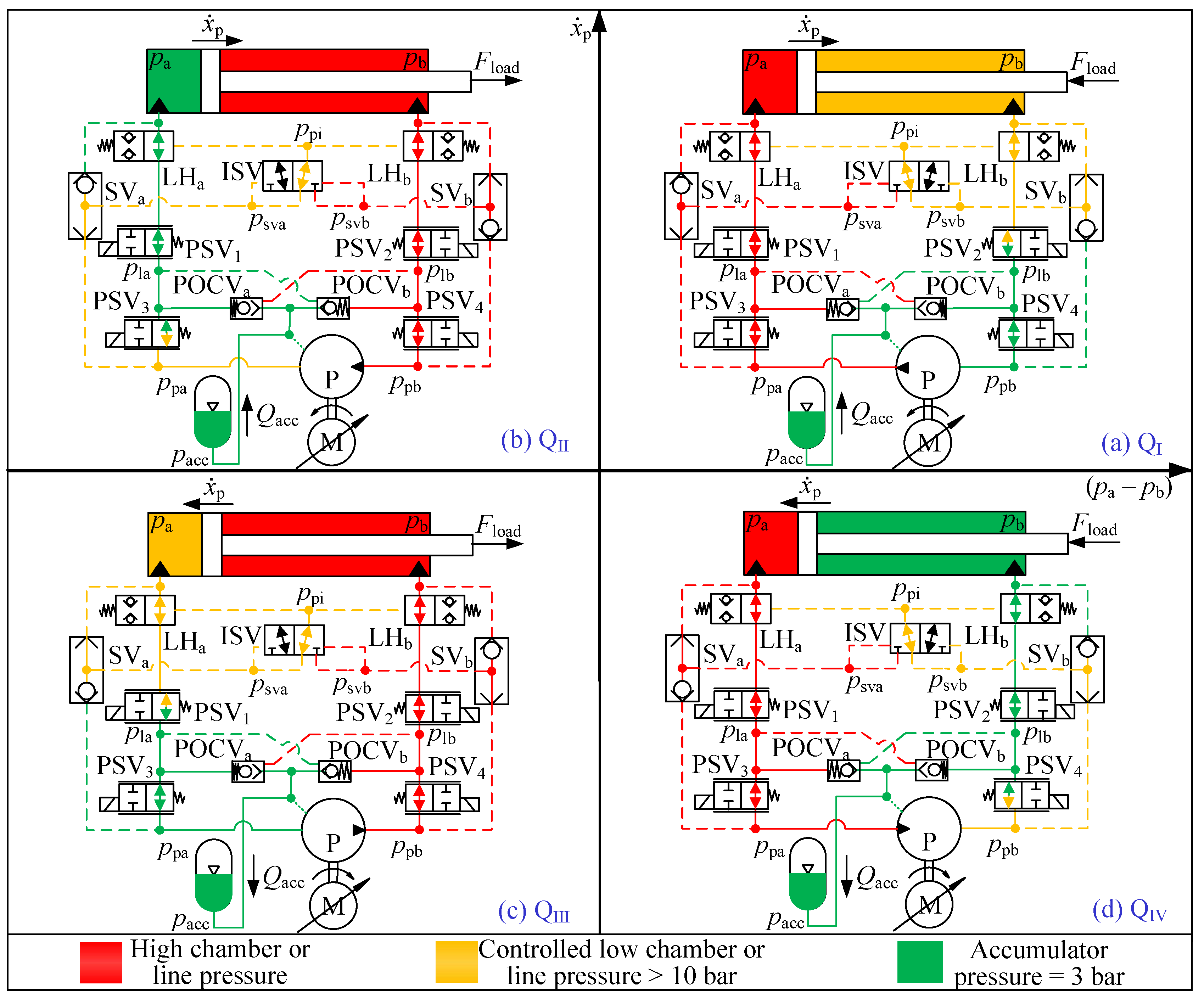
2.2. Oscillation Analysis in Four Quadrants
2.3. Linear Model Analysis
- dynamics of the electric servo motor,
- leakage in the hydraulic pump,
- variable bulk modulus based on the ratio of undissolved gas,
- cylinder friction,
- accumulator dynamics.
2.4. Oscillation Analysis Summary
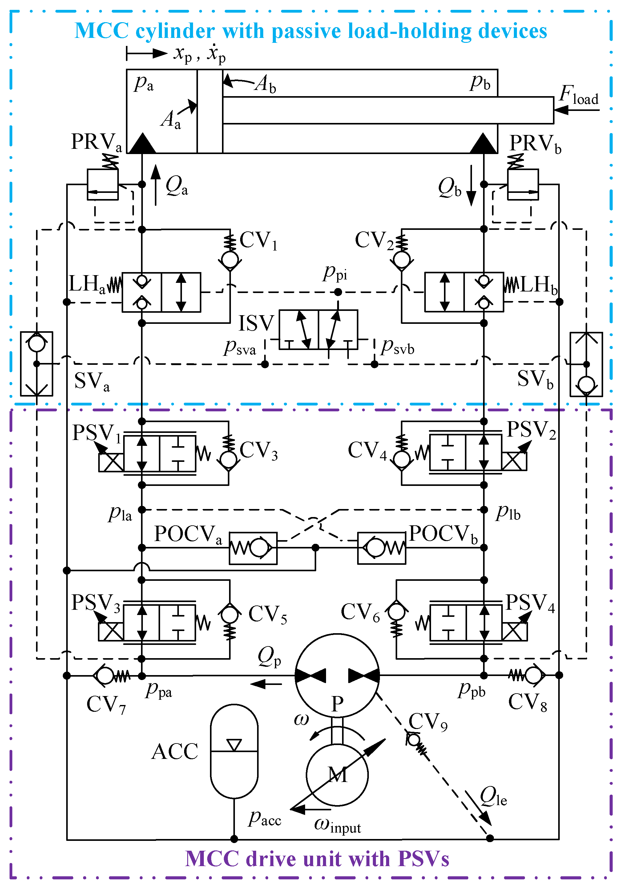
3. Proposed Oscillation-Free MCC
3.1. System Architecture
3.2. System Working Analysis
3.3. Mitigation of Mode Switching Oscillation
4. Systems Modeling
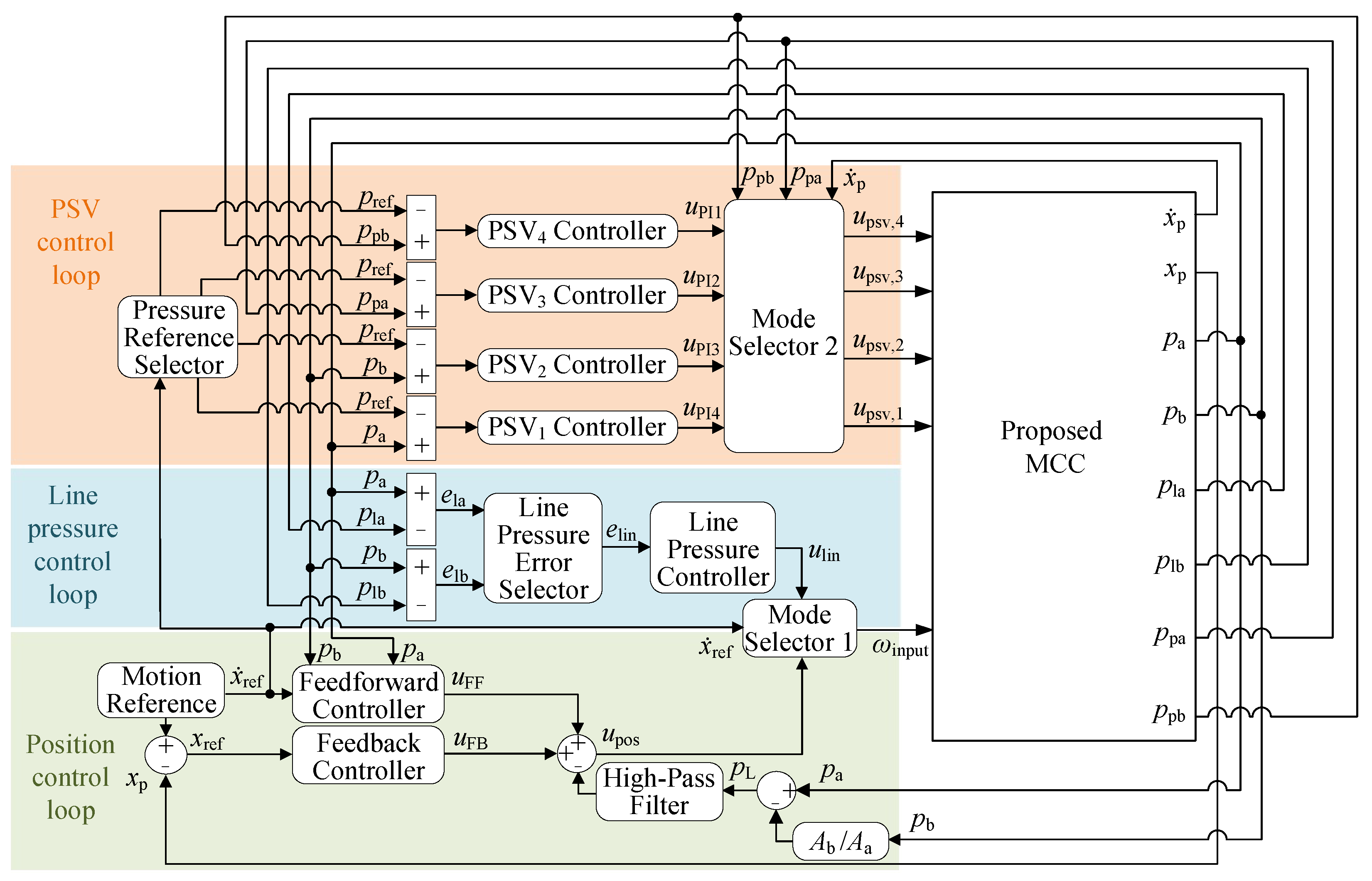
5. Controls
6. Simulation Results
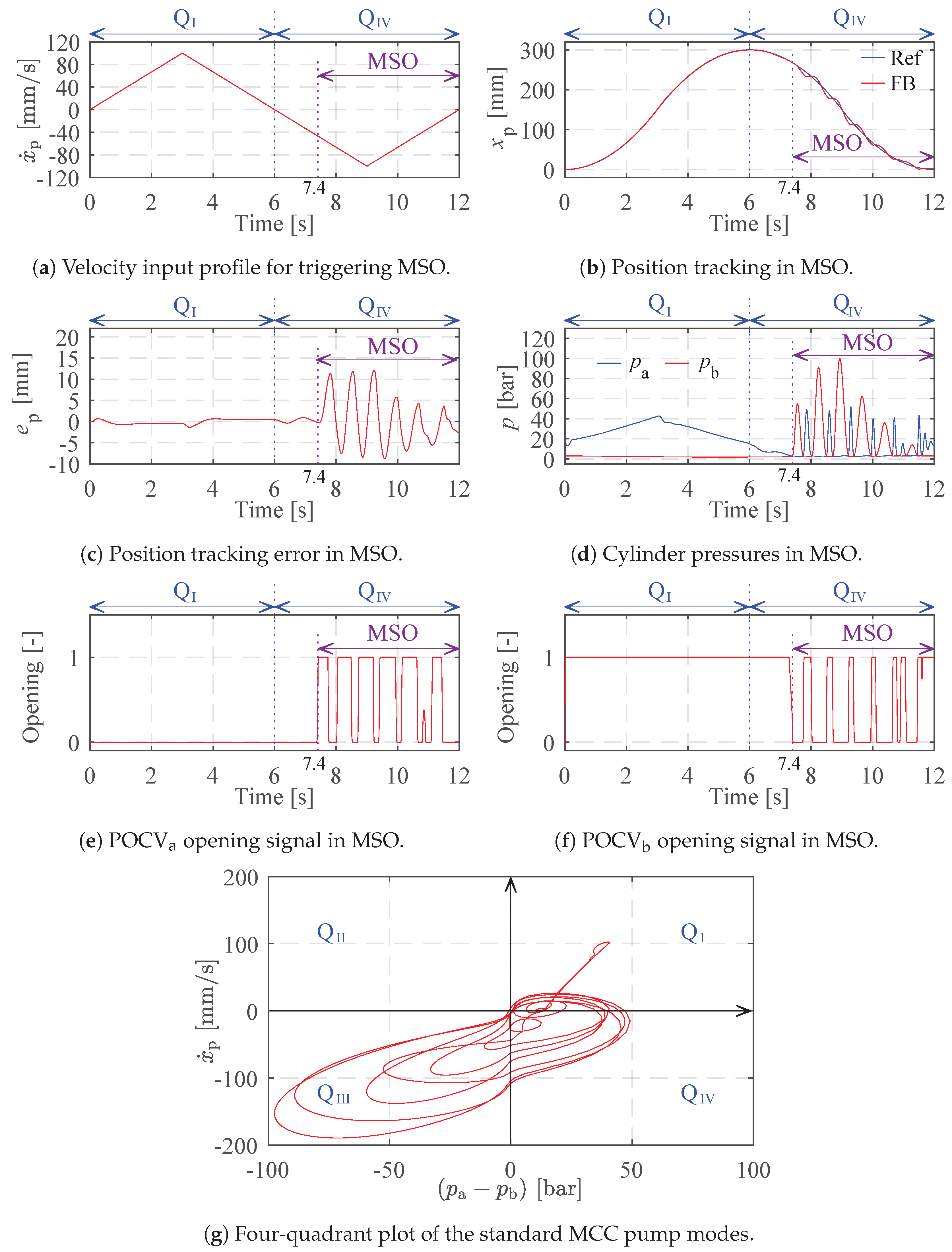
6.1. Triggered Mode Switching Oscillation in the Standard MCC
6.2. Mitigated MSO in the Proposed MCC
7. Discussion
8. Conclusions
- The root cause of mode switching oscillation in a standard one-motor-one-pump motor-controlled hydraulic cylinder is identified as the inherent difference between the four-quadrant operation of the cylinder component and that of the drive unit component.
- A stability analysis on a simplified and linearized model of a standard one-motor-one-pump motor-controlled hydraulic cylinder is carried out, confirming that the system in QIV is inherently oscillatory, and it is not feasible to mitigate that behavior from adjusting the regular system parameters.
- A new one-motor-one-pump motor-controlled hydraulic cylinder with system pressure control in four quadrants is proposed. Its capability to mitigate mode switching oscillation is described and analyzed.
- The effectiveness of the proposed one-motor-one-pump motor-controlled hydraulic cylinder and the control algorithm in mitigating the mode switching oscillation under certain operating conditions is demonstrated through the simulation results.
Author Contributions
Funding
Data Availability Statement
Conflicts of Interest
Abbreviations
| MCC | One-motor-one-pump motor-controlled hydraulic cylinder |
| MSO | Mode switching oscillation |
| VCC | Valve-controlled hydraulic cylinder |
| POCV | Pilot-operated check valve |
| ISV | Inverse shuttle valve |
| PSV | Proportional solenoid valve |
References
- Zhao, W.; Ebbesen, M.K.; Hansen, M.R.; Andersen, T.O. Enabling Passive Load-Holding Function and System Pressures Control in a One-Motor-One-Pump Motor-Controlled Hydraulic Cylinder: Simulation Study. Energies 2024, 17, 2484. [Google Scholar] [CrossRef]
- Hagen, D.; Padovani, D.; Choux, M. A comparison study of a novel self-contained electro-hydraulic cylinder versus a conventional valve-controlled actuator-part 2: Energy efficiency. Actuators 2019, 8, 78. [Google Scholar] [CrossRef]
- Ahn, K.K.; Yoon, J.I.; Truong, D.Q. Design and verification of a new energy saving electric excavator. In Proceedings of the 28th International Symposium on Automation and Robotics in Construction (ISARC 2011), Seoul, Republic of Korea, 29 June–2 July 2011; pp. 259–264. [Google Scholar]
- Williamson, C.; Ivantysynova, M. Pump Mode Prediction for Four-Quadrant Velocity Control of Valueless Hydraulic Actuators. In Proceedings of the JFPS International Symposium on Fluid Power, Toyama, Japan, 15–18 September 2008; pp. 323–328. [Google Scholar]
- Williamson, C.; Ivantysynova, M. Stability and Motion Control of Inertial Loads with Displacement Controlled Hydraulic Actuators. In Proceedings of the 6th FPNI PhD Symposium on Fluid Power, West Lafayette, IN, USA, 15–19 June 2010; pp. 499–514. [Google Scholar]
- Sun, Y.; Imam, A.; Wu, C.; Sepehri, N. Stability Study of a Pump-Controlled Circuit for Single Rod Cylinders via the Concept of Lyapunov Exponents. In Proceedings of the ASME/BATH 2017 Symposium on Fluid Power and Motion Control, Sarasota, FL, USA, 16–19 October 2017. [Google Scholar]
- Michel, S.; Weber, J. Electrohydraulic Compact-drives for Low Power Applications con- sidering Energy-efficiency and High Inertial Loads. In Proceedings of the 7th FPNI PhD Symposium on Fluid Power, Reggio Emilia, Italy, 27–30 June 2012; pp. 1–18. [Google Scholar]
- Imam, A.; Rafiq, M.; Jalayeri, E.; Sepehri, N. Design, implementation and evaluation of a pump-controlled circuit for single rod actuators. Actuators 2017, 6, 10. [Google Scholar] [CrossRef]
- Imam, A.; Rafiq, M.; Jalayeri, E.; Sepehri, N. A pump-controlled circuit for single-rod cylinders that incorporates limited throttling compensating valves. Actuators 2018, 7, 13. [Google Scholar] [CrossRef]
- Costa, G.K.; Sepehri, N. A Critical Analysis of Valve-Compensated Hydrostatic Actuators: Qualitative Investigation. Actuators 2019, 8, 59. [Google Scholar] [CrossRef]
- Costa, G.K.; Sepehri, N. Four-quadrant analysis and system design for single-rod hydrostatic actuators. J. Dyn. Syst. Meas. Control. Trans. ASME 2019, 141, 021011. [Google Scholar] [CrossRef]
- Gøytil, P.H.; Padovani, D.; Hansen, M.R. A novel solution for the elimination of mode switching in pump-controlled single-rod cylinders. Actuators 2020, 9, 20. [Google Scholar] [CrossRef]
- Wang, L.; Book, W.J.; Huggins, J.D. A Hydraulic Circuit for Single Rod Cylinders. J. Dyn. Syst. Meas. Control 2012, 134, 011019. [Google Scholar] [CrossRef]
- Wang, L.; Book, W.J. Using Leakage to Stabilize a Hydraulic Circuit for Pump Controlled Actuators. J. Dyn. Syst. Meas. Control 2013, 135, 061007. [Google Scholar] [CrossRef]
- Çalşkan, H.; Balkan, T.; Platin, B.E. A Complete Analysis and a Novel Solution for Instability in Pump Controlled Asymmetric Actuators. J. Dyn. Syst. Meas. Control 2015, 137, 091008. [Google Scholar] [CrossRef]
- Çalşkan, H.; Balkan, T.; Platin, B.E. A Complete Analysis for Pump Controlled Single Rod Actuators. In Proceedings of the 10th International Fluid Power Conference, Reggio Emilia, Italy, 8–10 March 2016; pp. 119–132. [Google Scholar]
- Kärnell, S.; Ericson, L. Hysteresis Control in Pump-Controlled Systems—A Way to Reduce Mode-Switch Oscillations in Closed and Open Circuits. Energies 2022, 15, 424. [Google Scholar] [CrossRef]
- Zhao, W.; Bhola, M.; Ebbesen, M.K.; Andersen, T.O. A Novel Control Design for Realizing Passive Load-Holding Function on a Two-Motor-Two-Pump Motor-Controlled Hydraulic Cylinder. Model. Identif. Control 2023, 44, 125–139. [Google Scholar] [CrossRef]


| System | Components | Manufacturer | Product Number |
|---|---|---|---|
| 1 & 2 | M | Bosch Rexroth | MS2N07-D |
| 1 & 2 | P | Bosch Rexroth | A10FZG |
| 1 & 2 | ACC | Bosch Rexroth | HAD3,5-250-2X |
| 1 & 2 | Cylinder | LJM | NH41-0-SD |
| 1 & 2 | POCV | Sun Hydraulics | CKEBXCN |
| 1 & 2 | PRV | Bosch Rexroth | RE 25402 |
| 2 | ISV | Bucher | HOSV-10 |
| 2 | LH | Sun Hydraulics | DKHSXHN |
| 2 | CV | Bosch Rexroth | RE20380 |
| 2 | PSV | Bosch Rexroth | KKDSR1PB |
| 2 | SV | Bosch Rexroth | MHSU2KA1X/420 |
Disclaimer/Publisher’s Note: The statements, opinions and data contained in all publications are solely those of the individual author(s) and contributor(s) and not of MDPI and/or the editor(s). MDPI and/or the editor(s) disclaim responsibility for any injury to people or property resulting from any ideas, methods, instructions or products referred to in the content. |
© 2024 by the authors. Licensee MDPI, Basel, Switzerland. This article is an open access article distributed under the terms and conditions of the Creative Commons Attribution (CC BY) license (https://creativecommons.org/licenses/by/4.0/).
Share and Cite
Zhao, W.; Ebbesen, M.K.; Hansen, M.R.; Andersen, T.O. Mitigating Mode Switching Oscillation in a One-Motor-One-Pump Motor-Controlled Hydraulic Cylinder via System Pressure Control: Simulation Study. Energies 2024, 17, 6334. https://doi.org/10.3390/en17246334
Zhao W, Ebbesen MK, Hansen MR, Andersen TO. Mitigating Mode Switching Oscillation in a One-Motor-One-Pump Motor-Controlled Hydraulic Cylinder via System Pressure Control: Simulation Study. Energies. 2024; 17(24):6334. https://doi.org/10.3390/en17246334
Chicago/Turabian StyleZhao, Wei, Morten Kjeld Ebbesen, Michael Rygaard Hansen, and Torben Ole Andersen. 2024. "Mitigating Mode Switching Oscillation in a One-Motor-One-Pump Motor-Controlled Hydraulic Cylinder via System Pressure Control: Simulation Study" Energies 17, no. 24: 6334. https://doi.org/10.3390/en17246334
APA StyleZhao, W., Ebbesen, M. K., Hansen, M. R., & Andersen, T. O. (2024). Mitigating Mode Switching Oscillation in a One-Motor-One-Pump Motor-Controlled Hydraulic Cylinder via System Pressure Control: Simulation Study. Energies, 17(24), 6334. https://doi.org/10.3390/en17246334