Article

Analysis of an Axial Field Hybrid Excitation Synchronous Generator

School of Electrical Engineering, Nanjing University of Aeronautics and Astronautics, Nanjing 211106, China
*
Author to whom correspondence should be addressed.
Energies 2024, 17(24), 6329; https://doi.org/10.3390/en17246329
Submission received: 13 November 2024 / Revised: 7 December 2024 / Accepted: 8 December 2024 / Published: 16 December 2024
(This article belongs to the Section F: Electrical Engineering)

Abstract

:
An axial field hybrid excitation synchronous generator (AF-HESG) is proposed for an independent power supply system, and its electromagnetic performance is studied in this paper. The distinguishing feature of the proposed generator is the addition of static magnetic bridges at both ends to place the field windings and the use of a sloping surface to increase the additional air-gap cross-sectional area. The advantage of the structure is that it achieves brushless excitation and improves the flux-regulation range. The structure and magnetic circuit characteristics are introduced in detail. Theoretical analysis of the flux-regulation principle is conducted by studying the relationship between field magnetomotive force, rotor reluctance, and air-gap flux density. Quantitative calculation is performed using a magnetomotive force (MMF)-specific permeance model, and the influence of the main parameters on the air-gap flux density and flux-regulation range is analyzed. Subsequently, magnetic field, no-load, and load characteristics are investigated through three-dimensional finite element analysis. The loss distribution is analyzed, and the temperature of the generator under rated conditions is simulated. Finally, a 30 kW, 1500 r/min prototype is developed and tested. The test results show good flux-regulation capability and stable voltage output performance of the proposed generator.

1. Introduction

The electric excitation generator has a simple structure and is low cost. By changing the field winding current, the air-gap magnetic field can be easily adjusted, achieving a wide range of output voltage and speed regulation characteristics. Disconnecting the excitation circuit can effectively demagnetize and achieve short-circuit and fault protection of the machine system. However, the field winding loss makes the system efficiency relatively low, and it is difficult to achieve high power density. Moreover, due to the use of a brush and slip ring structure, the reliability is low [1,2].
The permanent magnet (PM) generator eliminates the structure of the brush and slip ring and also eliminates the excitation power, resulting in higher efficiency. Compared with other types of electric excitation machines with the same power and speed, the efficiency can usually be improved by 3–5%. However, it is difficult to adjust the voltage of the permanent magnet generator itself, and it is also difficult to demagnetize during faults. It needs to rely on a converter to achieve voltage regulation [3].
Hybrid excitation technology combines two excitation methods in a reasonable way, combining the advantages of the high-power density of permanent magnet machines and the adjustable magnetic field of electric excitation machines [4]. The development of electrification (such as independent power supply systems) has become the most popular trend to promote energy conservation. The independent power sources are influenced by both the engine and the load. To ensure the stability of power generation systems, the research focus is on generators with wide power regulation ranges and stable voltage output. Domestic and foreign scholars have conducted research on hybrid excitation technology and have made significant progress in the field of independent power generation, such as aircraft, vehicle power supplies, and mobile power supplies [5,6].
In order to realize the brushless excitation technology of the hybrid excitation machine, there are usually three methods based on the placement of PM and field winding. The first is that both the PM and field winding are on the rotor [7,8,9,10], such as two-stage excitation generators and harmonic excitation hybrid excitation generators. This method is equipped with an additional set of windings on the stator or rotor and provides dc power through the rotating rectifier. It has high excitation efficiency and good waveform quality [11]. However, the use of a rotating rectifier limits some applications.
The second is that the PM and the field winding are both on the stator [12,13,14,15,16], such as in a doubly salient hybrid excitation machine. This method has a simple rotor structure without PM and winding. The rotor structure is simple, the mechanical strength is high, and it is easy to achieve a brushless structure. This type of machine has a wide range of application prospects in high-speed situations. In order to ensure effective slot filling, the stator slots need to be deepened. And to ensure that the magnetic circuit of the stator yoke is not saturated, it is necessary to increase the outer diameter of the stator, thereby increasing the volume of the entire generator.
The third is to place the PM on the rotor and the field winding on the stator [17,18,19,20], such as in a dual-direction hybrid excitation synchronous generator [21]. The characteristic of this machine is that the axial flux path passes through the shell and cover. This method has an axial magnetic circuit and an additional air gap by adding the magnetic parts, and the structure is relatively complex, but the excitation method is simple and reliable.
An AF-HESG is presented in this paper, with an additional axial magnetic bridge. The rotor adopts a claw-pole-like structure, with the field winding placed in the axial magnetic bridge, and the field flux path does not pass through the permanent magnet. It achieves brushless excitation. The flux-regulation principle is analyzed based on the relationship between MMF, reluctance, and air-gap flux density. Analytical calculation of air-gap flux density using the MMF-specific permeance model. Finite element analysis is utilized to analyze magnetic field distribution, operating characteristics, and temperature field. Finally, a prototype is constructed and tested to verify the theoretical and simulation results.

2. Machine Topology and Operating Principle
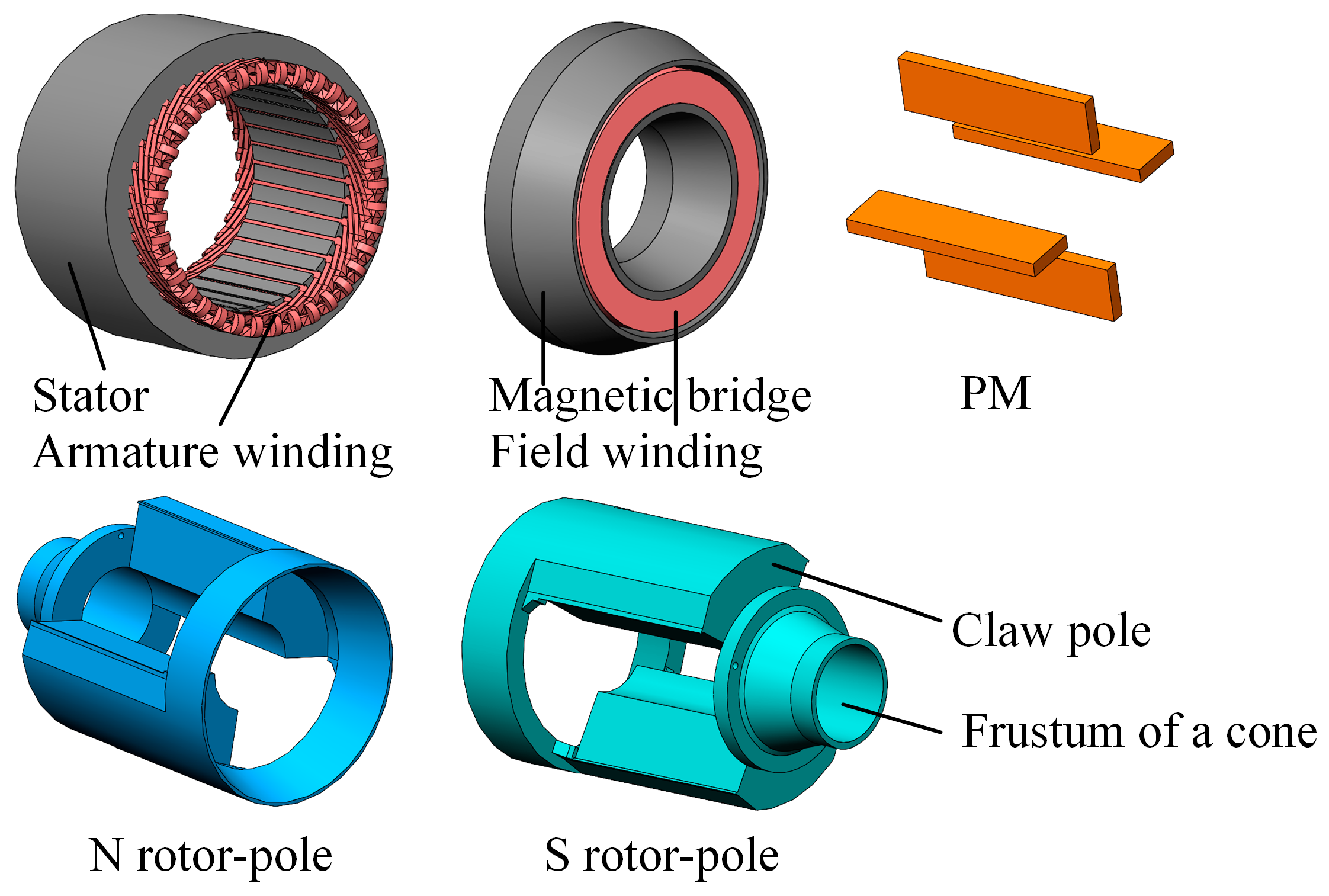
2.1. Topology

The sectional view of the AF-HESG proposed in this paper is shown in Figure 1. And the diagram of various components of the AF-HESG is shown in Figure 2. The stator is mainly composed of a stator core, an armature winding, an axial magnetic bridge with a side opening, and the ring-type field winding. The rotor is mainly composed of an N rotor-pole, an S rotor-pole, and a permanent magnet. The claw pole and the frustum of a cone together form a rotor pole. The permanent magnet is located between the N-pole and S-pole rotor claw poles. In particular, the stator core is made of silicon steel sheet, and the rest are solid steel. The field windings are placed in the opening of the axial magnetic bridge, and there are additional air gaps between the axial magnetic bridge and the rotor. The additional air gap is a sloping surface. The schematic diagram of the generator system is shown in Figure 3. The field windings at both ends are connected in series and powered by a DC power supply, and the armature winding is connected to the load. Table 1 shows the structure parameters of the AF-HESG.

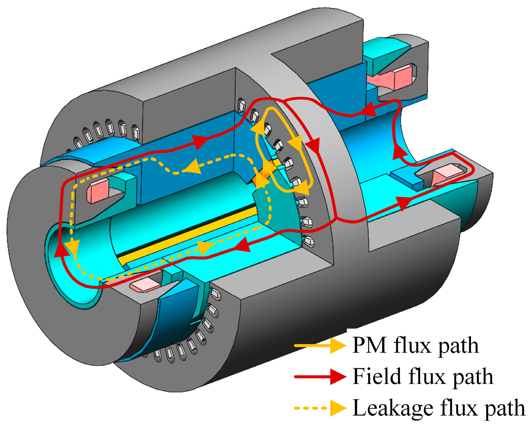
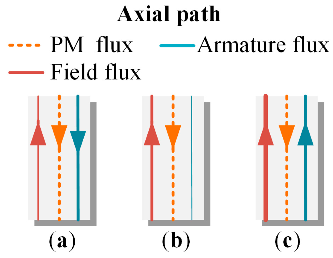
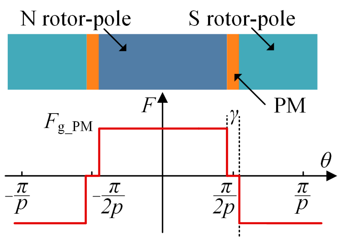
2.2. Operating Principle

The AF-HESG is primarily composed of three flux paths: the PM flux path, the field flux path, and the leakage flux path, as depicted in Figure 4. The PM generates radial air-gap flux and axial leakage flux. The leakage flux passes through the axial magnetic bridge, additional air gaps, and then returns to the PM. The field flux path is in parallel with the PM flux path. This enables the generator to have flexible flux-regulation capability.
In order to have a simpler understanding of the principle of the AF-HESG, Figure 5 shows the equivalent magnetic circuit and electrical circuit under flux-enhancing. Considering leakage flux as PM flux, it can be seen that the armature flux mainly depends on the PM flux and field flux. The direction of the armature flux in the radial flux path is clear, but in the axial flux path, its direction depends on the field flux. As shown in Figure 6, when the field flux is small, the direction of the armature flux is opposite to that of the field flux. As the field flux increases, the direction of the armature flux becomes the same as that of the field flux. By weakening the PM flux through the axial magnetic circuit, not only can parallel brushless excitation be achieved, but also a larger flux-regulation range can be obtained.

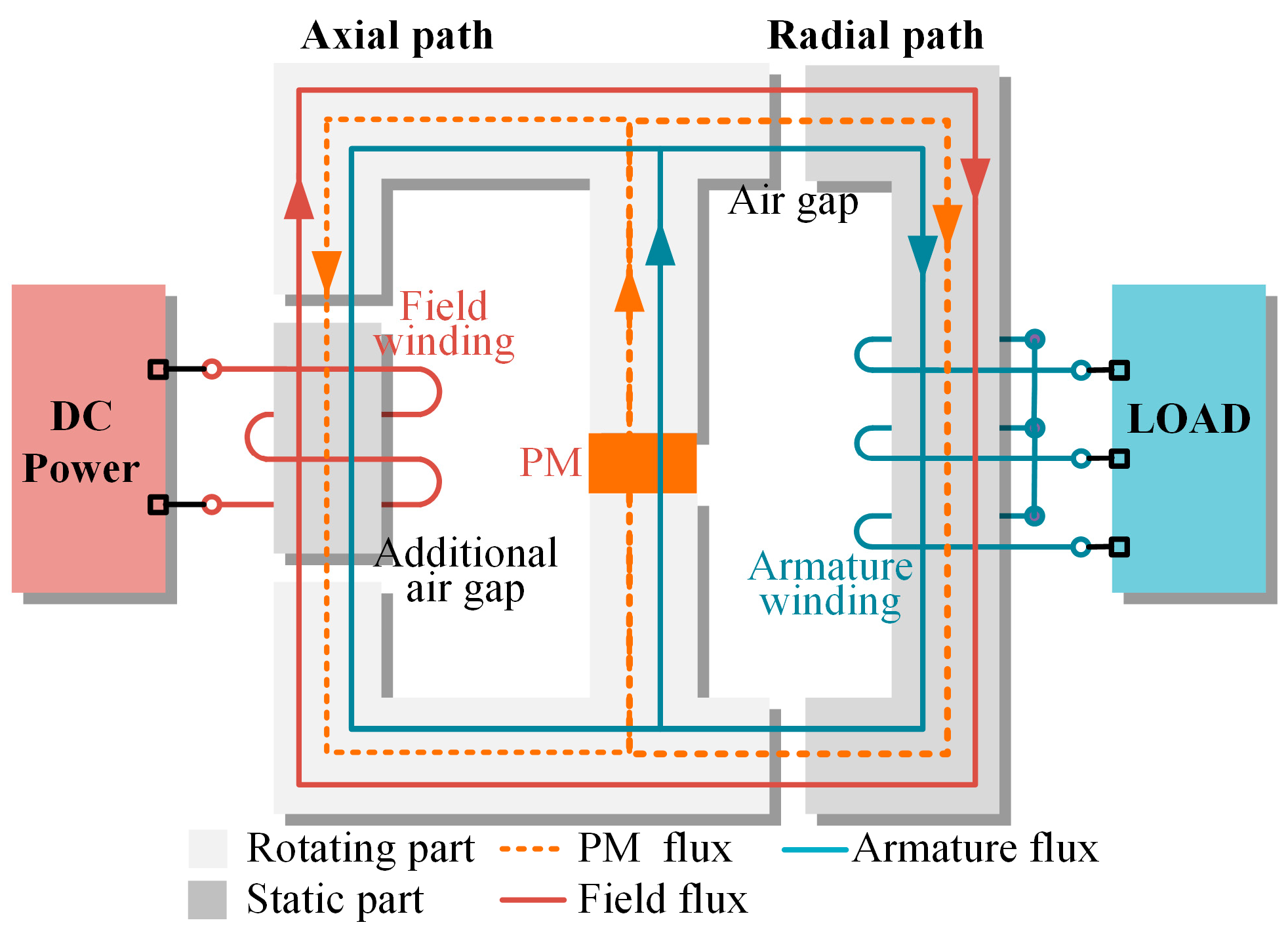
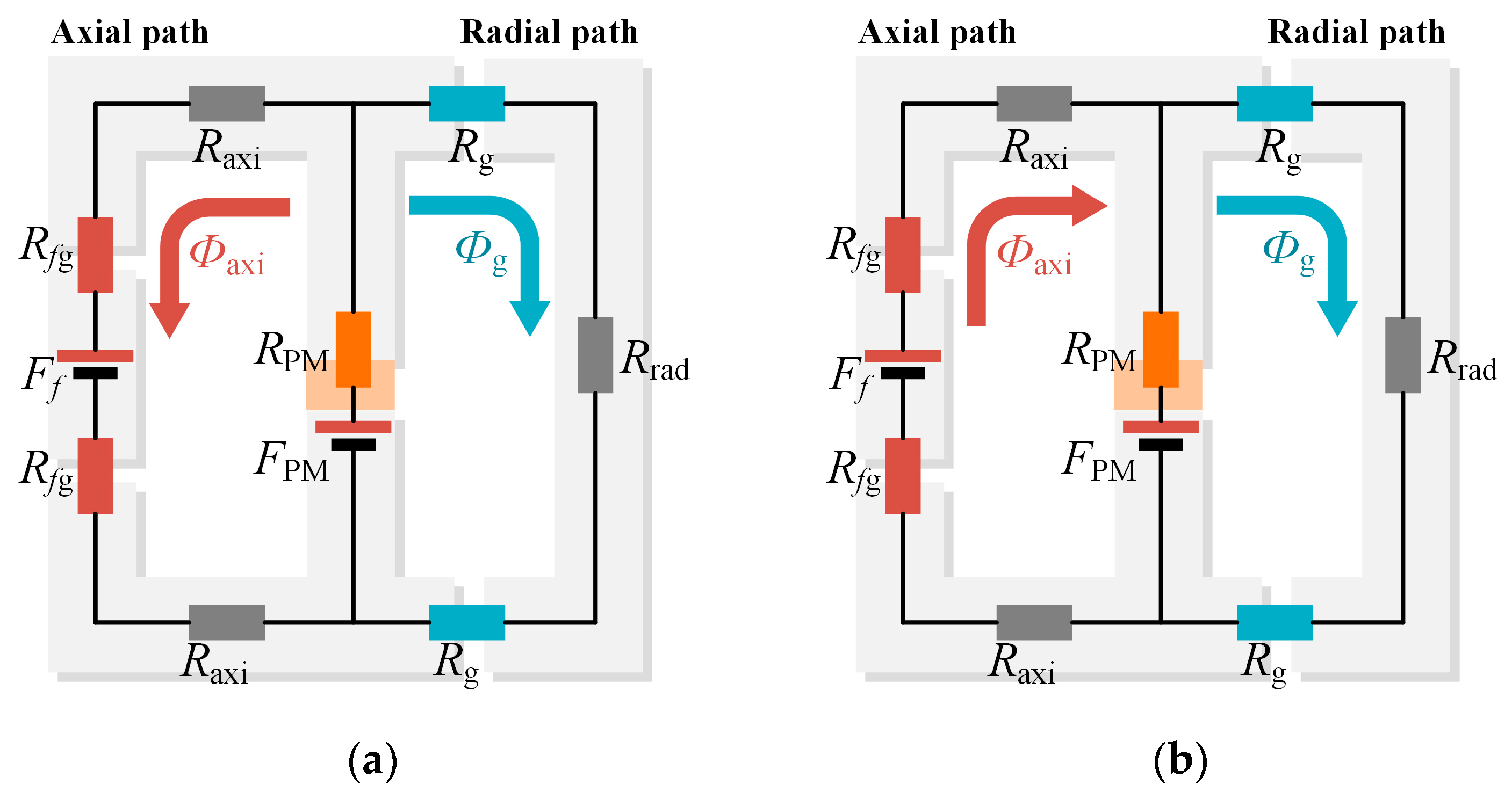
2.3. Equivalent Magnetic Circuit Model

In order to analyze the flux-regulation ability of the AF-HESG more accurately, it is necessary to conduct a quantitative analysis. Equivalent magnetic circuit (MEC) models are established for Case 1 and Case 3, as shown in Figure 7. Rg and Rfg are the main air-gap reluctances and the additional air-gap reluctances, respectively; ϕg and ϕaxi are the air-gap flux and axial flux, respectively; ϕPM is the PM flux, RPM and FPM are the equivalent internal reluctance and the equivalent MMF of the PM, respectively, Ff is the field MMF, and Rrad and Raxi are the equivalent reluctances of the radial and axial core. As the field MMF increases, the direction of axial flux ϕaxi changes.
Based on the MEC, the relationship between the air-gap flux, MMF, and reluctance generated by PMs ϕg_PM and field windings (FW) ϕg_f can be expressed as follows:
ϕ g _ PM = F PM 2 R f g + 2 R axi 2 R g + R rad R PM + 2 R f g + 2 R axi R PM + 2 R g + R rad 2 R f g + 2 R axi ϕ g _ f = F f R PM 2 R g + R rad R PM + 2 R f g + 2 R axi R PM + 2 R g + R rad 2 R f g + 2 R axi
where the PM MMF can be calculated as follows:
F PM = B r h PM μ 0 μ PM
where Br is the PM remanent flux density, hPM is the thickness of PM, and μPM is the relative permeability of PM. And the field MMF can be calculated as follows:
F f = N f I f
where Nf is the number of turns of field winding. If is the dc field current. The main air-gap flux is the sum of the air-gap flux generated by the PM and the field winding. The corresponding air gap MMF can be expressed as follows:
F g _ PM = 2 R g ϕ g _ PM F g _ f = 2 R g ϕ g _ f F g = F g _ PM + F g _ f
The MMF-specific permeance method can obtain the waveform of air-gap flux density by calculating the air-gap MMF and permeance. To simplify the model, iron core saturation and edge effects are ignored. Figure 8 shows the waveform of the ideal air-gap MMF, where γ is the angle corresponding to the thickness of the PM and p is the number of pole pairs.
The air-gap MMF generated by PM is an even function with a period of 2π/p. Its waveform is expanded into a Fourier series as follows [22]:
F g _ PM ( θ ) = i = 1 , 3 F g _ PM i cos i p θ F g _ PM i = 4 F g _ PM i π sin i π 2 cos i p γ 2
The air-gap MMF generated by FW is the same. The total MMF of the air gap can be calculated by the following:
F g ( θ ) = F g _ PM ( θ ) + F g _ f ( θ )
The air-gap specific permeance can be expressed as follows:
Λ g ( θ ) = δ g μ 0 Λ gs ( θ ) Λ gr ( θ )
where Λgs(θ) and Λgr(θ) represent the air-gap specific permeances considering stator slotting and rotor pole arc, respectively. They can be calculated by the following:
Λ gs θ = Λ gs 0 + m = 1 Λ gsm cos m Z s θ Λ gr θ = Λ gr 0 2 + n = 1 Λ grn cos n p θ
where Λgs0 and Λgr0 are the dc components and Λgsm and Λgrm are the mth and nth harmonic amplitudes. The air-gap flux density can be calculated by the following:
B g ( θ ) = F g ( θ ) × Λ g ( θ )
Figure 9 shows the calculation results of the MMF-specific permeance method. The distribution of the air-gap MMF generated by PM and FW is shown in Figure 9a. The waveform of the air-gap specific permeances, considering stator slotting and rotor pole arc, obtained by adding up 100 terms of the Fourier series, is shown in Figure 9b. The waveform of the air-gap flux density is shown in Figure 9c. Figure 10 shows the relationship of the air-gap flux density and field current. It can be observed that as the field current increases, the air-gap flux density increases. Due to the neglect of iron core saturation and leakage flux during calculation, there is a certain difference from the simulation results, but the overall trend is similar.
According to the above calculation, the air-gap flux density is affected by the parameters of AF-HESG, and the main parameters and affected parameters are shown in Table 2. And the variation range of these parameters is normalized to obtain the influence of the main parameters on the air-gap MMF, air-gap flux density, and flux-regulation ability, as shown in Figure 11. The flux-regulation range kf is defined as follows:
k f = B g B g _ PM B g _ PM × 100 %
where Bg is the air-gap flux density with field current applied and Bg_PM is the air-gap flux density under PM excitation only.
From Figure 11, it can be observed that the width of the PM wPM mainly affects the air-gap MMF generated by the PM, thereby increasing the air-gap flux density. Both Bg and Bg_PM are increasing, reducing the kf. The length of the main air-gap δg also has a significant impact on the air-gap flux density, but it has little effect on the kf. The reason is that the air gap permeance Λg is also changing, as shown in Figure 12. The longer the additional air-gap length δfg, the lower the air-gap MMF generated by the FW, the lower the air-gap flux density, and the Bg_PM remains unchanged. So, the kf is significantly reduced. The larger the cross-sectional area of the additional air gap, the higher the air gap flux density and the kf. Therefore, the AF-HESG adopts an inclined additional air gap, which can effectively increase the flux-regulation capability.

3. Performance Analysis of AF-HESG

In order to analyze the flux-regulation ability of the AF-HESG, the magnetic field and the operating characteristics are analyzed by using a three-dimensional finite element model. The loss distribution is analyzed, and the temperature of the generator under rated conditions is simulated.

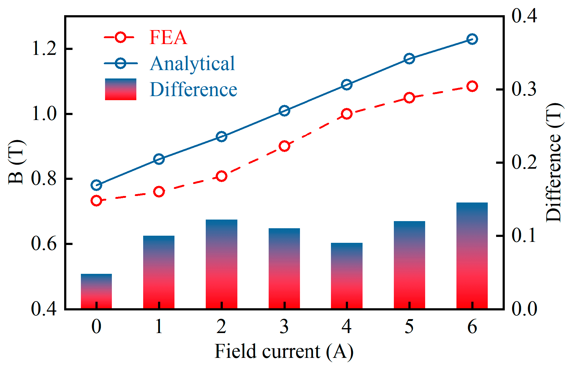
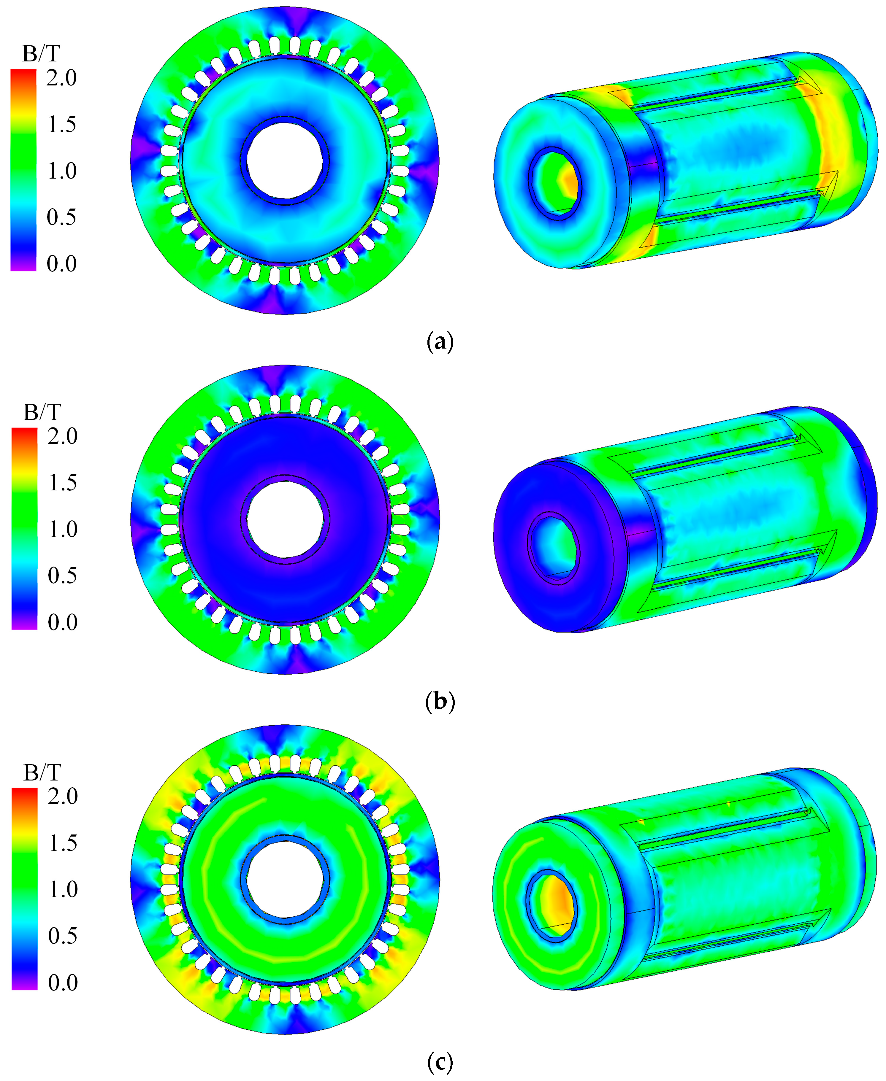
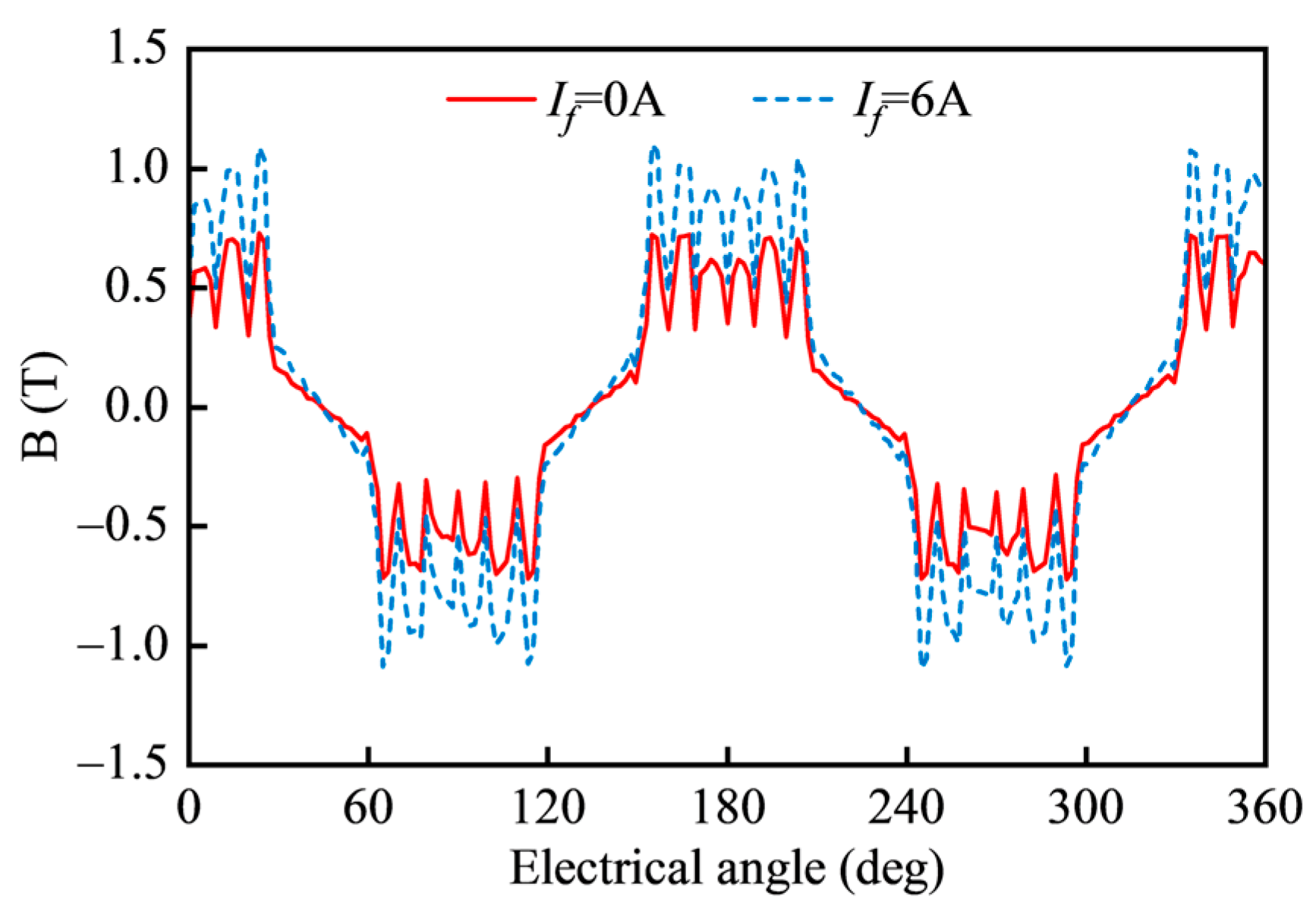
3.1. Magnetic Field Analysis

Through static finite element analysis (FEA), magnetic field distributions with different If are obtained, as shown in Figure 13. Figure 14 shows the distribution waveform of the air-gap flux density under different field currents. It can be observed that when the field current If is 0 A, part of the PM flux passes through the axial magnetic circuit. When If increases, the flux density of the radial path increases, while the axial path decreases. As the field current continues to increase, the main air-gap flux increases significantly. When If is 6 A, the AF-HESG reaches a saturated state. The result of magnetic field distributions conforms to the operating principle of Figure 6.

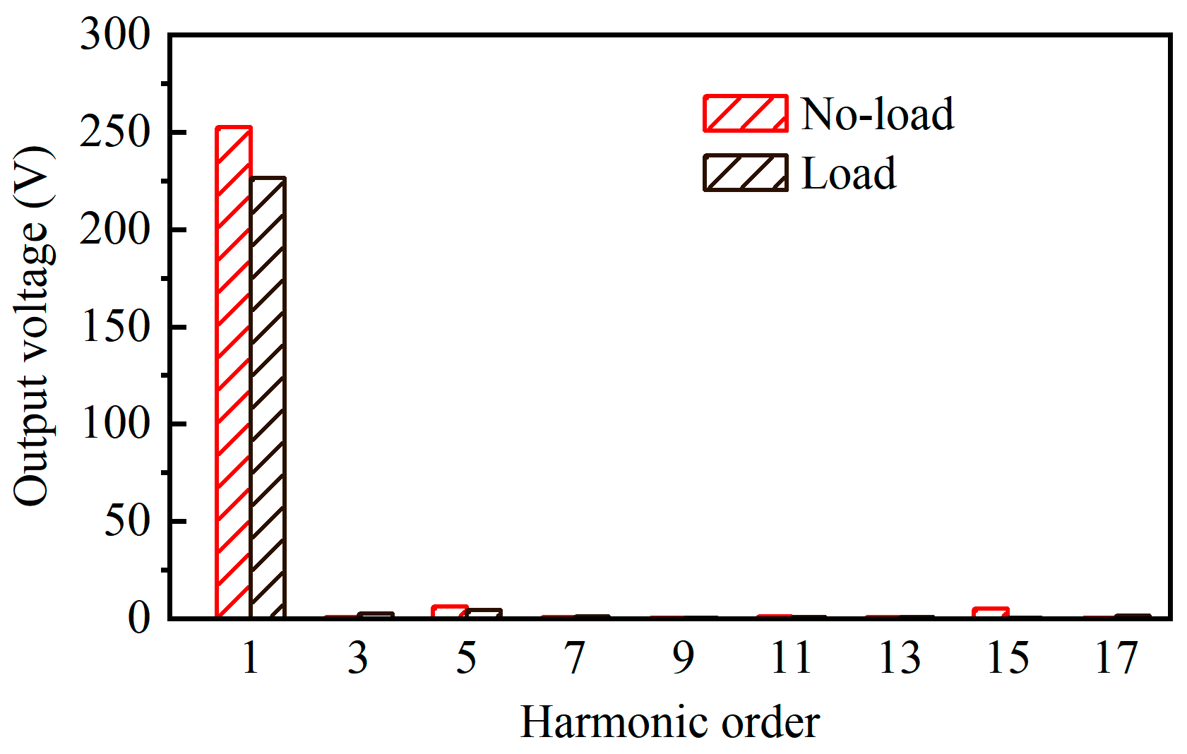
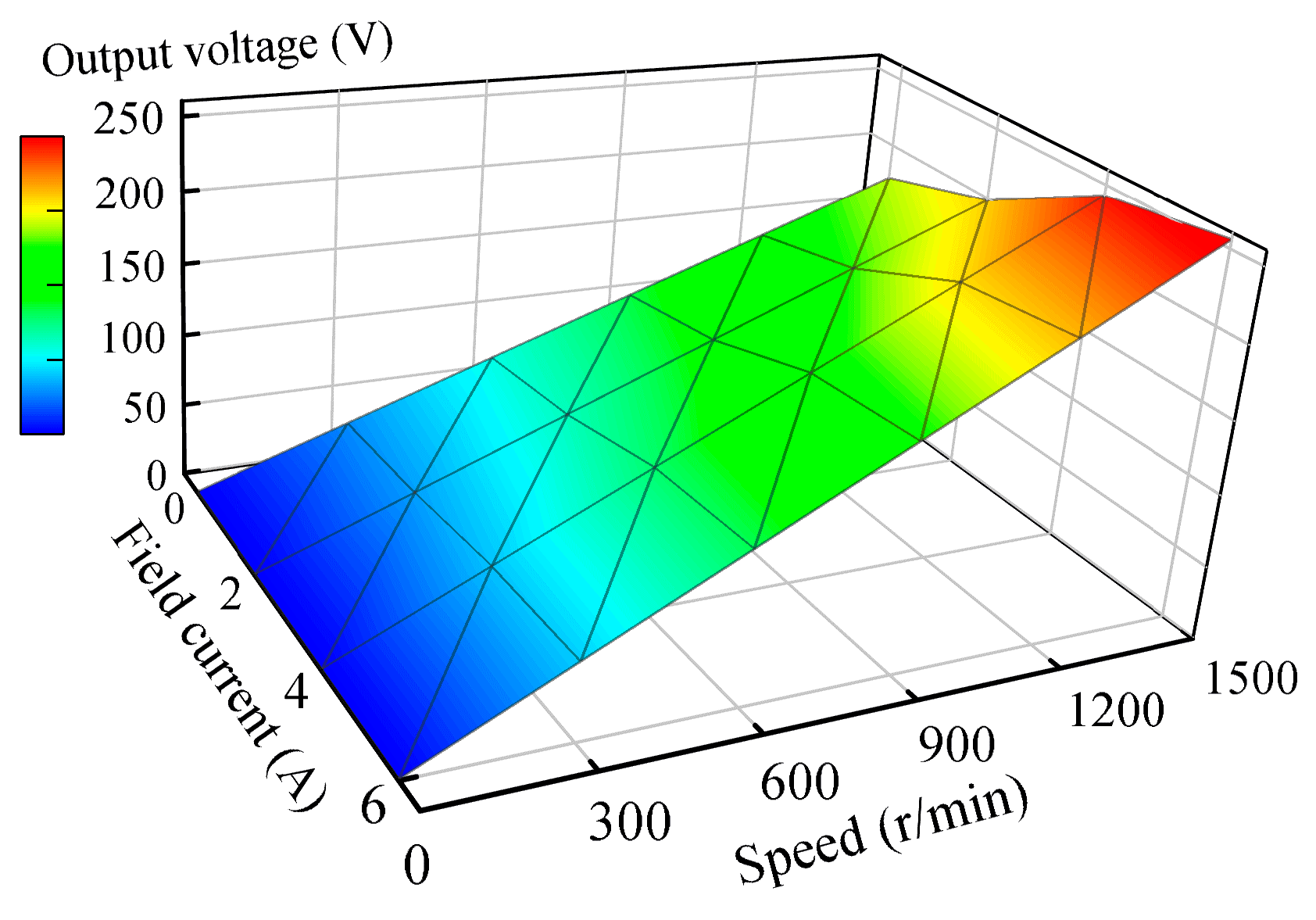
3.2. Operating Characteristics Analysis

Through transient FEA, the no-load voltage and the rated load voltage under different field currents are obtained, as shown in Figure 15. When the field current is 6 A, the effective value of the no-load voltage is 250 V, and the rated load voltage is 234 V. Due to the filtering effect of the armature winding, the sine degree of the rated load voltage waveform is higher. Figure 16 shows the voltage harmonics under no-load and loaded conditions.
Figure 17 shows the relationship among the no-load output voltage, the field current, and speed, i.e., the no-load characteristics of the AF-HESG. It is obvious that the no-load output voltage increases linearly with the speed. When If increases from 0 A to 2 A, the output voltage increases slowly because the field MMF needs to partially offset the PM leakage flux. When If reaches 2 A, the output voltage increases faster, while when If is between 4 A and 6 A, the voltage increases slowly because the iron core is beginning to saturate.
The external characteristics at rated speed for different field currents are depicted in Figure 18. It can be observed that with constant field current, the output voltage decreases as the load current increases. The voltage adjustment rate represents the degree of steady-state voltage drop when the load changes, and can be defined as follows:
Δ U = U no - load U N U N × 100 %
The voltage adjustment rate of the generator is relatively low, approximately 9.36%. As the field current increases, the output voltage increases while the load current remains constant. The voltage regulation range is 46.5%.
To maintain stable voltage output, it is necessary to adjust the field current. The regulation characteristics, i.e., the relationship between field current and load current with the output voltage Uout set to 220 V, are shown in Figure 19. It can be observed that as the load current increases, the required field current also increases.

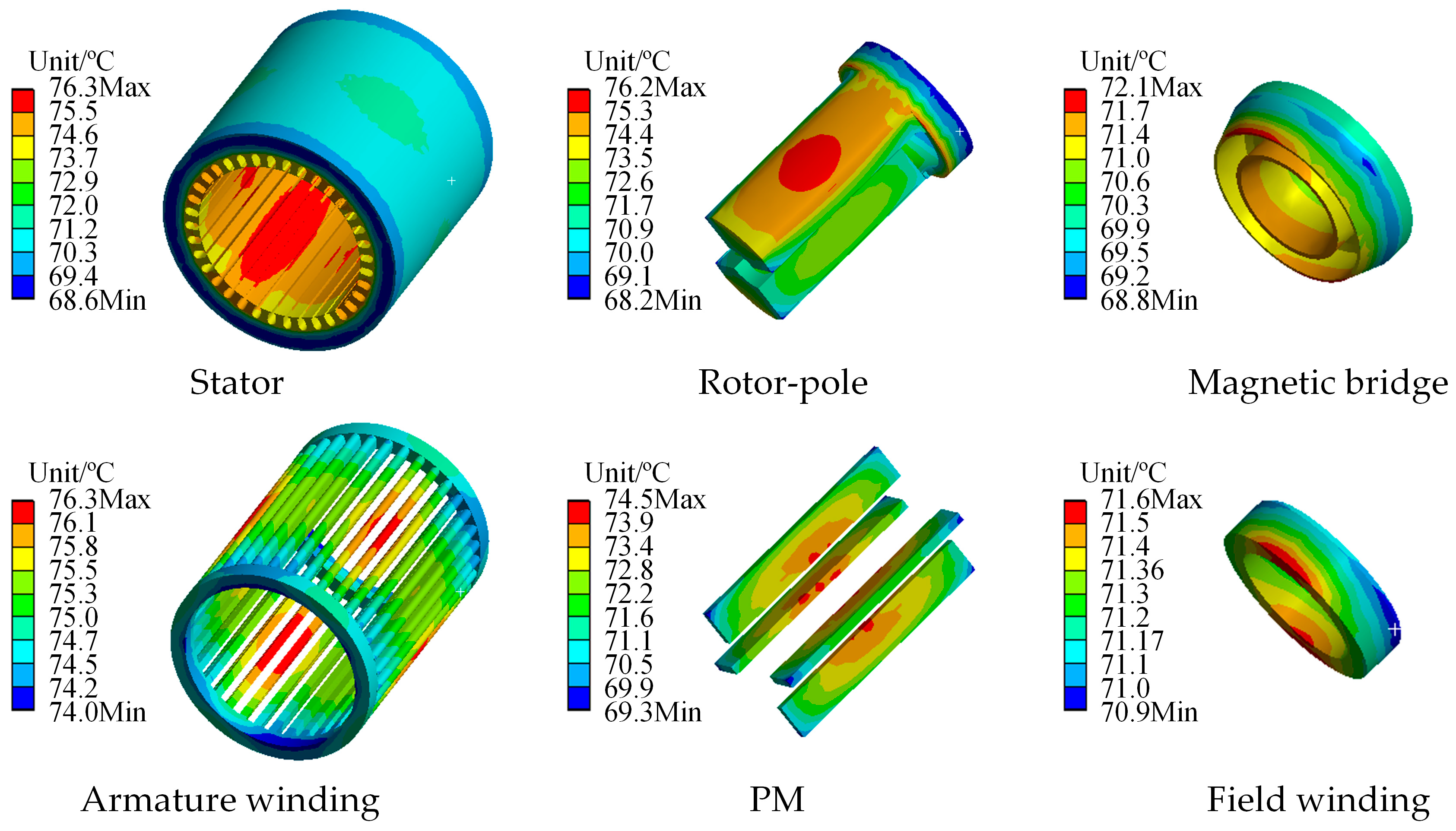
3.3. Loss and Temperature Field Analysis

The component of the loss under different field currents at the rated speed and load is shown in Figure 20. The main loss is the iron loss of the rotor and the copper loss of the armature winding WA because the rotor is made of solid steel with high eddy current loss. With the addition of field current, the losses of all components have increased, except for the magnetic bridge, because, without field current, most of the PM flux passes through the magnetic bridge. The PM loss is relatively small. The efficiency of the AF-HESG under rated conditions is about 89%.
In order to avoid damage to the generator caused by high temperature, the temperature field is checked. Due to the complexity of the winding end model, the winding end is equivalent to a circular ring. A three-dimensional temperature field finite element model is established. The losses during AF-HESG will serve as a heat source in temperature field analysis, achieving electromagnetic thermal unidirectional coupling calculation. The method is to input the loss results in the form of heat generation rate into the temperature field model. The heat generation rate is the heat generation power per unit volume, and it can be calculated by the following:
Q = P loss V
where Ploss is the losses of each part of the generator, and V represents the effective volume of the corresponding part. The results are shown in Table 3.
The accurate selection of thermal conductivity and convective heat transfer coefficient on the surface of each component of the AF-HESG determines the accuracy of temperature calculation. The calculation method for the equivalent thermal conductivity of the air gap is as follows [23]:
λ g = 0.0019 η 2.9084 R e g 0.4614 ln ( 3.33361 η ) η = D 2 / D i 1
where D2 is the outer diameter of the rotor, Di1 is the inner diameter of the stator, and Reg is the Reynolds number of the air gap. Based on relevant engineering practice experience, the thermal conductivity λt and convective heat transfer coefficients αt of each component are shown in Table 4.
The FEA results of the steady-state temperature field of each component under rated load conditions are shown in Figure 21. It can be observed that the temperature is relatively average, with a maximum temperature of around 76 degrees. Therefore, the result conforms to the temperature range for normal operation of the generator.

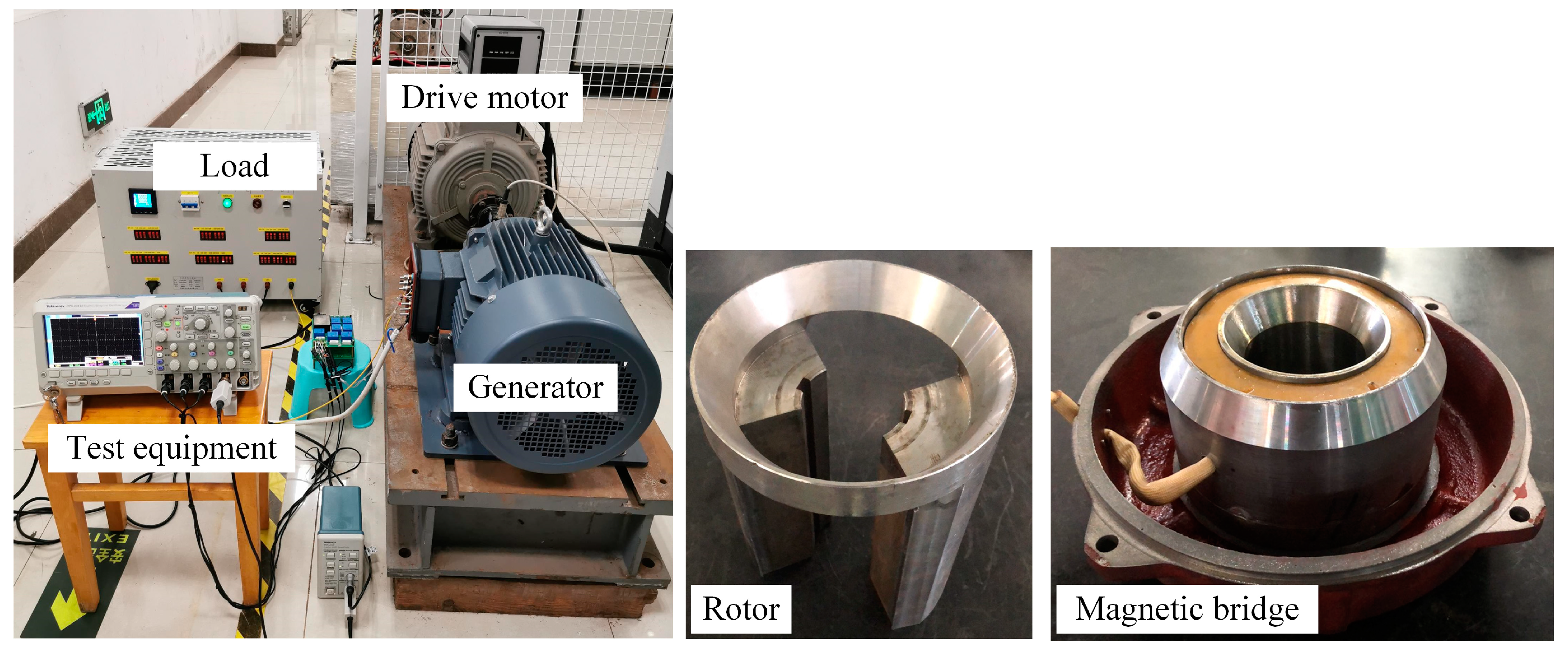
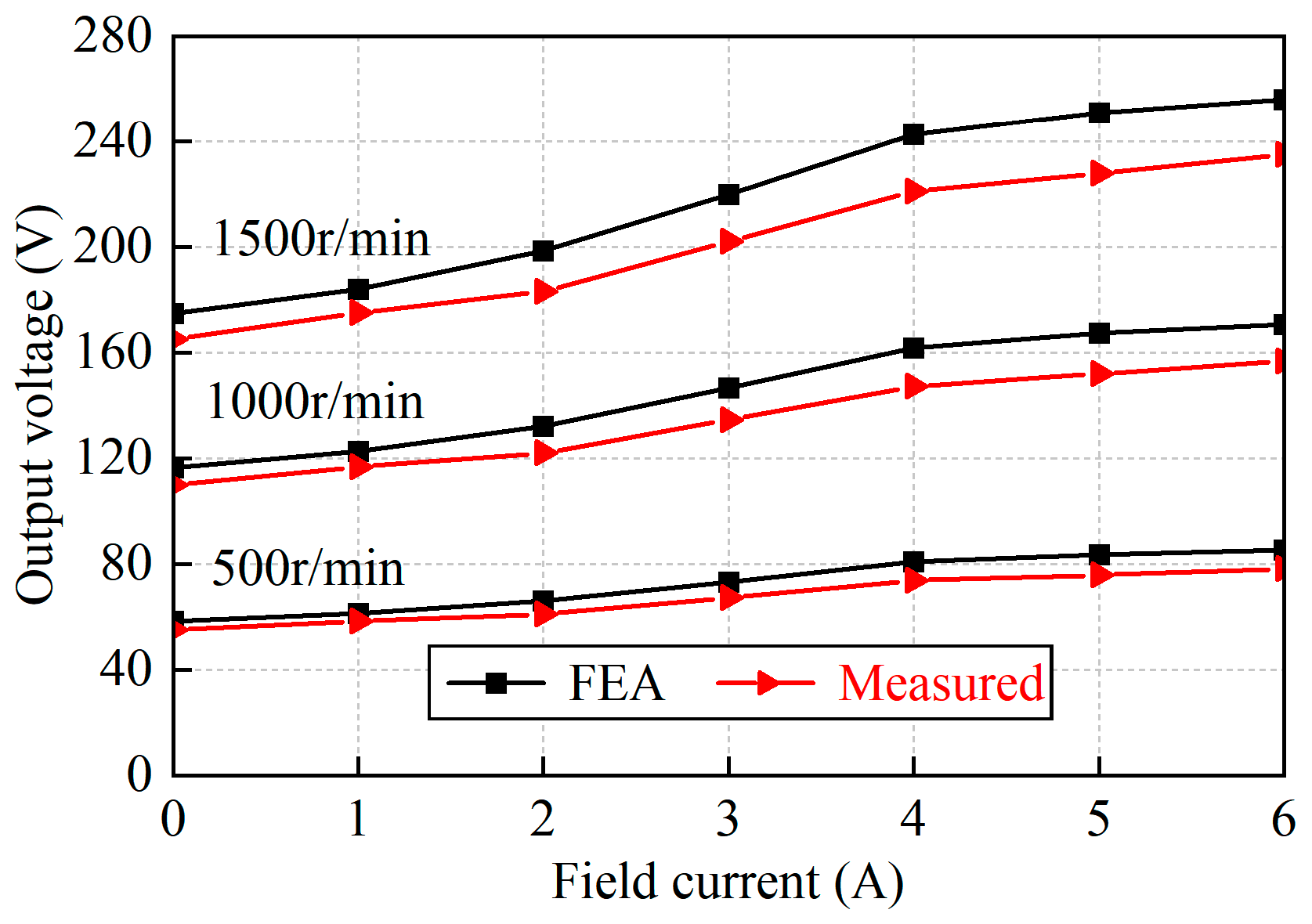
4. Experimental Verification

The prototype of the AF-HESG is manufactured and the test platform is built, as shown in Figure 22. The platform mainly consists of the AF-HESG, the prime motor, a dc power supply, and the three-phase load. The proposed generator is driven by the prime mover during testing. The dc power supply provides the dc field current.
Figure 23 shows the measured no-load output voltage waveform under If = 0 A and If = 6 A. It is observed that the three-phase voltage is symmetrical, and as the field current increases, the effective value of no-load output voltage increases from 166 V to 235 V. Figure 24 shows the measured load output voltage waveform under If = 0 A and If = 6 A. As the field current increases, the effective value of load output voltage increases from 155 V to 212 V. It can be concluded that the voltage waveform is generally smoother than no-load voltage due to the filtering effect of the windings.
By varying the speed and field currents, the no-load characteristics at different speeds can be obtained, as shown in Figure 25. Compared to the simulation, the measured output voltage is relatively small, but the overall trend conforms to the simulation results because it is difficult to ensure that the structural parameters and additional air gap size are completely consistent with the design values in actual processing. Figure 26 shows the measured external characteristics under If = 6 A. It can be observed that as the load current increases, the output voltage decreases and the output power increases. Under rated conditions, the actual output power of the AF-HESG is 27.3 kW, and the efficiency is about 85%. Figure 27 shows a comparison of the regulation characteristics at rated speed with an output voltage of 220 V. It can be observed that as the load current increases, a higher field current is required to maintain voltage stability in the experiment, yet the overall trend remains consistent.

5. Conclusions

In this paper, a detailed study was conducted on the operating principle and electromagnetic performance of the AF-HESG through the MMF-specific permeance method, three-dimensional finite element analysis, and prototype testing. The conclusions are as follows:
(1)
AF-HESG provides a field flux path without passing through permanent magnets by adding an axial magnetic circuit, achieving brushless excitation.
(2)
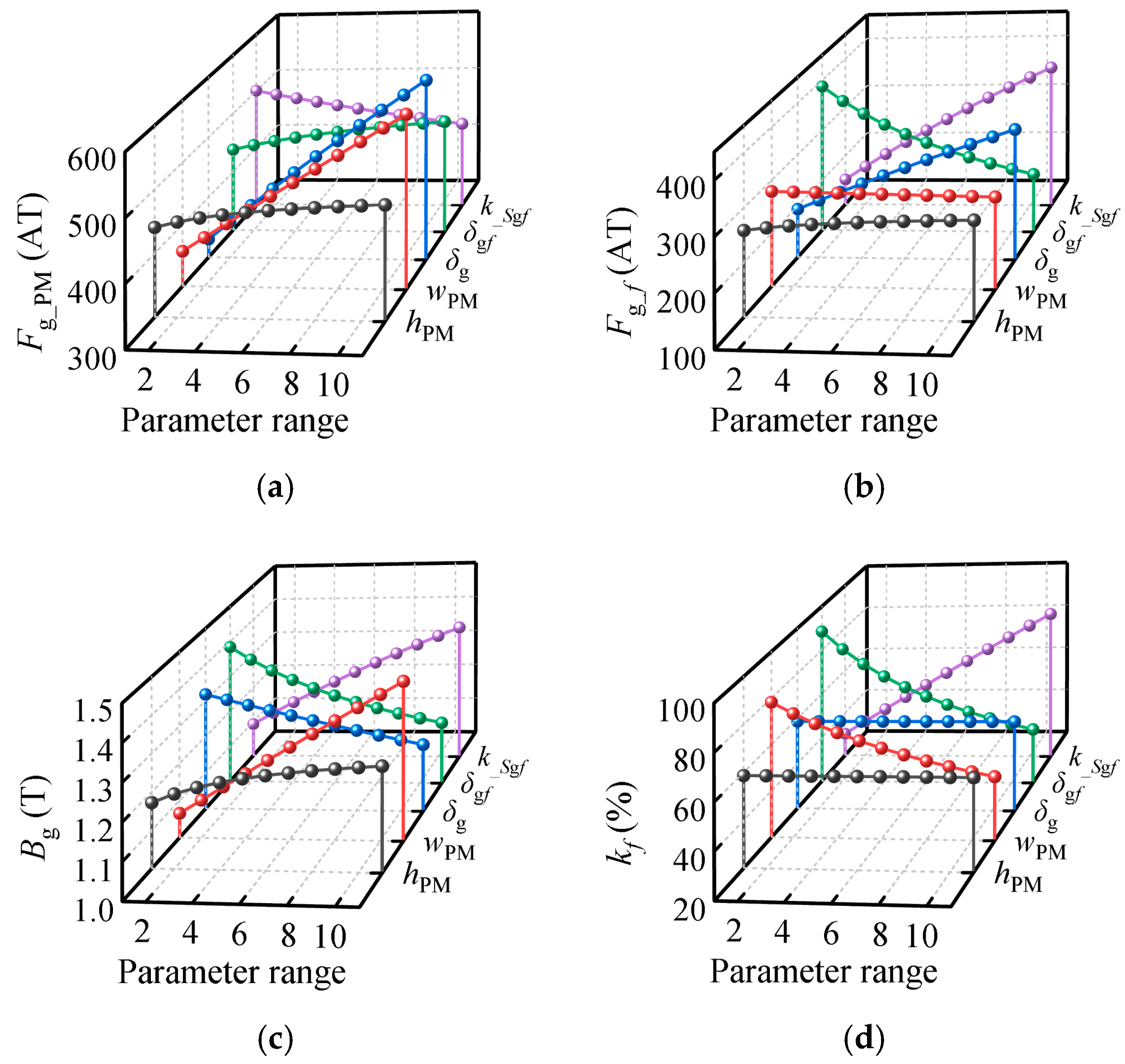
According to the analysis of the air-gap flux density, it can be concluded that AF-HESG can increase the flux-regulation range by changing the additional air-gap length and cross-sectional area, so the AF-HESG adopts an inclined additional air gap, which can effectively increase the flux-regulation capability.
(3)
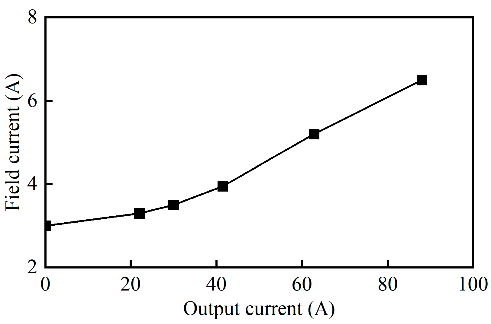
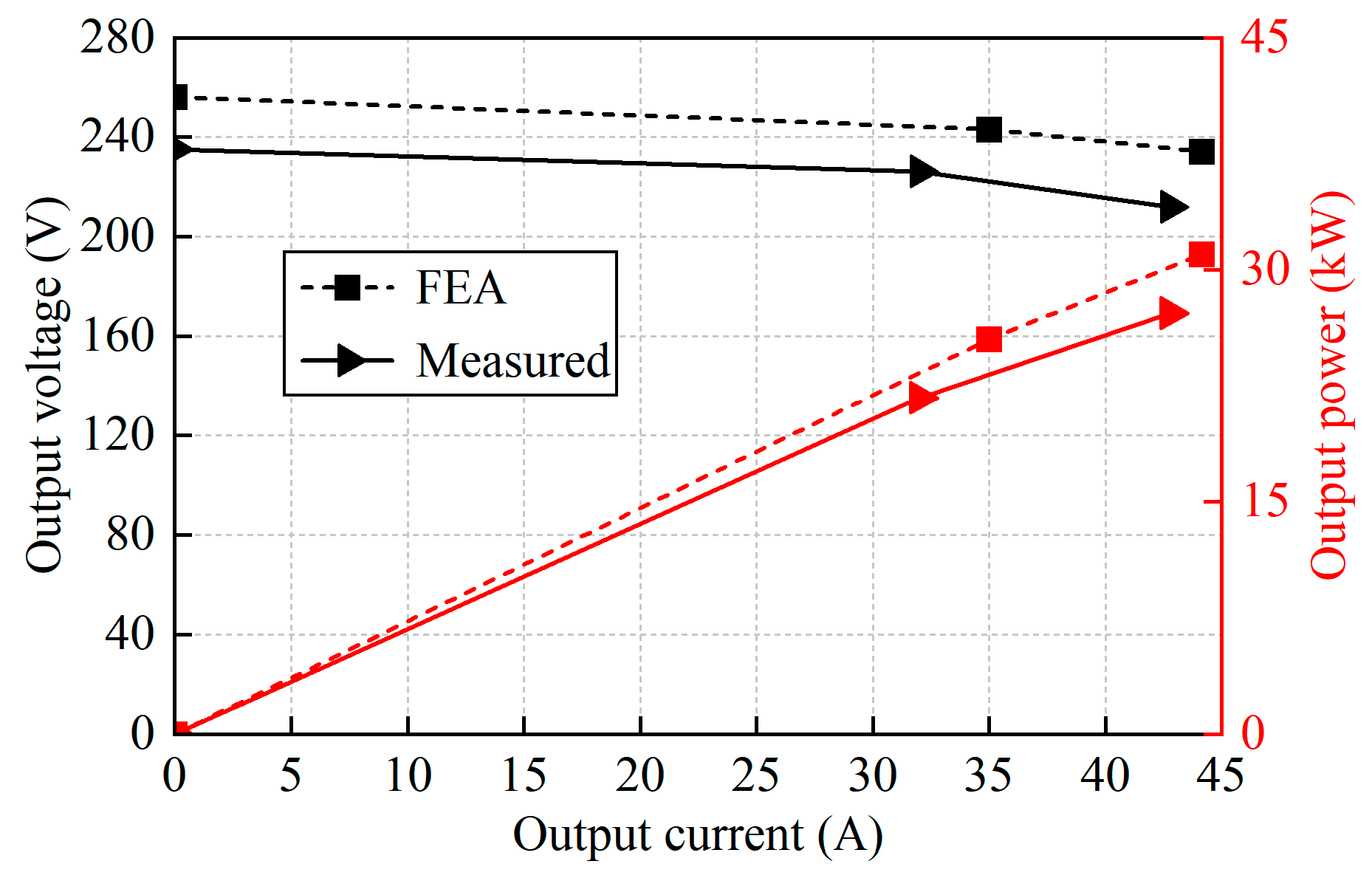
Finite element simulations are conducted to validate the model and analyze the output characteristics of the generator. The load voltage regulation efficiency is 46.5%. The voltage adjustment rate is 9.36%. Due to the axial magnetic circuit of the generator, the rotor is made of solid materials. Therefore, the eddy current loss of the rotor is relatively large. And the temperature is relatively average under rated load conditions.
(4)
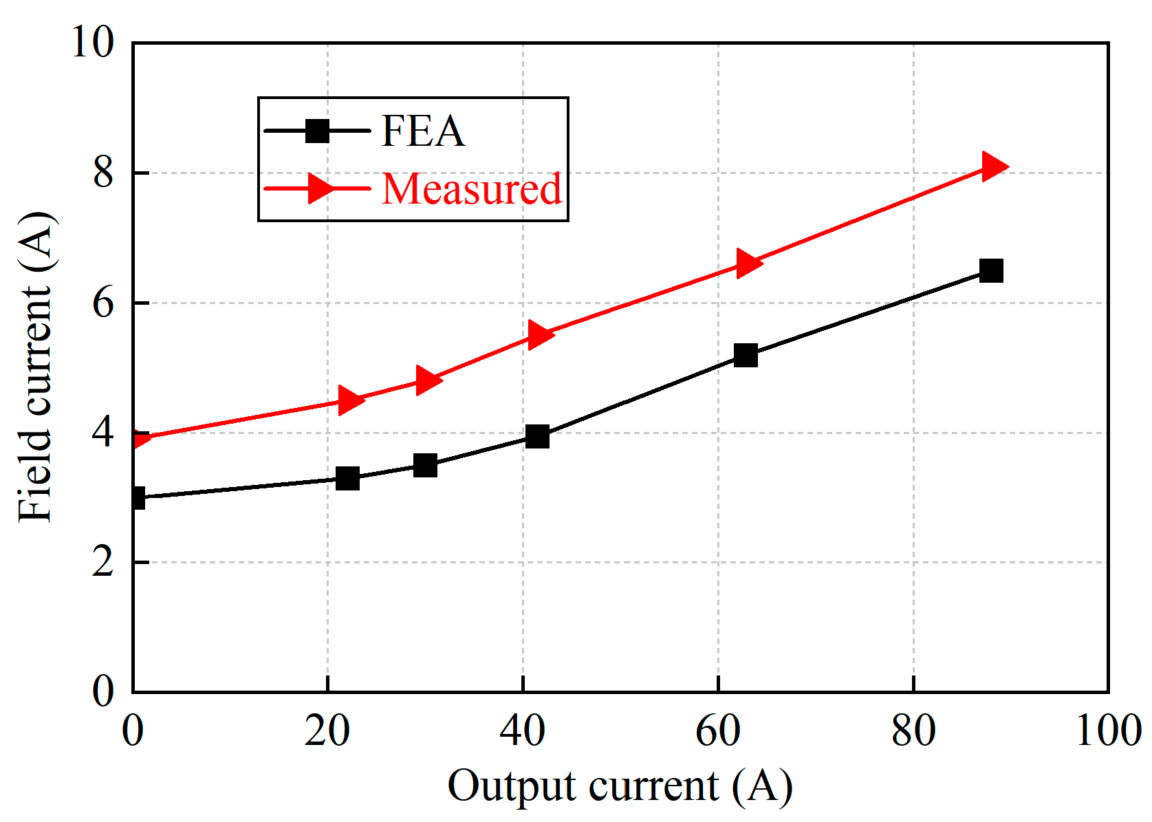
A prototype is manufactured. Due to the relatively complex structure of the generator, processing is difficult, and it is not easy to mass produce. The feasibility of the generator principle is verified through comparison between the measured results and simulations. And it reflects that AF-HESG has good magnetic field regulation ability and stable voltage output ability.

Author Contributions

Conceptualization, C.L.; methodology, J.Y.; software, J.Y.; validation, J.Y.; investigation, S.Z.; data curation, J.Y.; writing—original draft preparation, J.Y.; writing—review and editing, C.L. and S.Z.; supervision, C.L. and S.Z.; project administration, C.L. All authors have read and agreed to the published version of the manuscript.

Funding

This research was funded by the Postgraduate Research & Practice Innovation Program of Jiangsu Province under Grant KYCX21_0213, the National Natural Science Foundation of China under Project 52277054, the China Postdoctoral Science Foundation under Grant 2023M741674, and the Fundamental Research Funds for the Central Universities under Grant NE2024003.

Data Availability Statement

The original contributions presented in this study are included in the article. Further inquiries can be directed to the corresponding author.

Conflicts of Interest

The authors declare no conflicts of interest.

References

  1. Zhu, Z.Q.; Cai, S. Overview of Hybrid Excited Machines for Electric Vehicles. In Proceedings of the 2019 Fourteenth International Conference on Ecological Vehicles and Renewable Energies (EVER), Monte-Carlo, Monaco, 8–10 May 2019; pp. 1–14. [Google Scholar]
  2. Zhu, S.; Liu, C.; Wang, K.; Zhou, Z.; Yu, J. Structure and Operating Performance of a Double Electrical Excitation Synchronous Generator with Embedded Brushless Synchronous Exciter Utilizing DC-Field Excitation. IEEE Trans. Energy Convers. 2022, 37, 50–64. [Google Scholar] [CrossRef]
  3. Michieletto, D.; Cinti, L.; Bianchi, N. Hybrid Excitation PM Synchronous Motors: Part I—Per Unit Analysis. IEEE Trans. Energy Convers. 2022, 37, 487–494. [Google Scholar] [CrossRef]
  4. Shushu, Z.; Chuang, L.; Yinhang, N.; Jie, T. A Two-Stage Brushless Excitation Method for Hybrid Excitation Synchronous Generator. IEEE Trans. Magn. 2015, 51, 8105411. [Google Scholar] [CrossRef]
  5. Geng, H.; Zhang, X.; Tong, L.; Ma, Q.; Xu, M.; Zhang, Y.; Wang, L. Performance Optimization Analysis of Hybrid Excitation Generator with the Electromagnetic Rotor and Embedded Permanent Magnet Rotor for Vehicle. IEEE Access 2021, 9, 163640–163653. [Google Scholar] [CrossRef]
  6. Zhang, Y.; Zhang, X.; Ren, J.; Yan, S.; Wang, L.; Pang, X.; Liu, W.; Kong, Z. Study of Electromagnetic Characteristics of Brushless Reverse Claw Pole Electromagnetic and Permanent Magnet Hybrid Excitation Generator for Automobiles. IEEE Trans. Energy Convers. 2024, 39, 1288–1300. [Google Scholar] [CrossRef]
  7. Li, J.; Wang, K.; Zhu, S.S.; Liu, C. Integrated-Induction-Based Hybrid Excitation Brushless DC Generator with Consequent-Pole Rotor. IEEE Trans. Transp. Electrific. 2022, 8, 2233–2248. [Google Scholar] [CrossRef]
  8. Sun, L.; Zhang, Z.; Gu, X.; Yu, L. Analysis of a Hybrid Excitation Brushless DC Generator with an Integrated Shared-Flux-Path Exciter. IEEE Trans. Ind. Electron. 2021, 68, 6672–6681. [Google Scholar] [CrossRef]
  9. Ayub, M.; Jawad, G.; Kwon, B. Consequent-Pole Hybrid Excitation Brushless Wound Field Synchronous Machine with Fractional Slot Concentrated Winding. IEEE Trans. Magn. 2019, 55, 8203805. [Google Scholar] [CrossRef]
  10. Li, J.; Wang, K.; Liu, C. Improvement of Integrated-Induction-Based Hybrid Excitation Brushless DC Generator by Employing Novel Consequent-Pole Rotor. IEEE Trans. Ind. Electron. 2022, 69, 12042–12054. [Google Scholar] [CrossRef]
  11. Zhang, Z.; Han, J.; Wang, C. A Brushless Hybrid Excited Starter-Generator with Independent Excitation Flux Circuit for Aircraft AC Power Generation. IEEE Trans. Transp. Electrific. 2024, 10, 4689–4698. [Google Scholar] [CrossRef]
  12. Xu, L.; Zhu, X.; Jiang, T.; Niu, S. Design and Optimization of a Partitioned Stator Hybrid Excited Machine with Inset PM From Perspective of Airgap Field Harmonics. IEEE Trans. Energy Convers. 2023, 38, 2871–2883. [Google Scholar] [CrossRef]
  13. Zhao, X.; Niu, S.; Zhang, X.; Fu, W. Flux-Modulated Relieving-DC-Saturation Hybrid Reluctance Machine with Synthetic Slot-PM Excitation for Electric Vehicle In-Wheel Propulsion. IEEE Trans. Ind. Electron. 2021, 68, 6075–6086. [Google Scholar] [CrossRef]
  14. Li, X.; Shen, F.; Yu, S.; Xue, Z. Flux-Regulation Principle and Performance Analysis of a Novel Axial Partitioned Stator Hybrid-Excitation Flux-Switching Machine Using Parallel Magnetic Circuit. IEEE Trans. Ind. Electron. 2021, 68, 6560–6573. [Google Scholar] [CrossRef]
  15. Wei, F.; Zhu, Z.Q.; Yan, L.; Qi, J. Investigation of Stator/Rotor Pole Number Combinations and PM Numbers in Consequent-Pole Hybrid Excited Flux Reversal Machine. IEEE Trans. Energy Convers. 2022, 37, 2092–2106. [Google Scholar] [CrossRef]
  16. Zhao, X.; Jiang, J.; Niu, S.; Wang, Q. Slot-PM-Assisted Hybrid Reluctance Generator with Self-Excited DC Source for Stand-Alone Wind Power Generation. IEEE Trans. Magn. 2022, 58, 8700106. [Google Scholar] [CrossRef]
  17. Hou, J.; Geng, W.; Li, Q.; Zhang, Z. 3-D Equivalent Magnetic Network Modeling and FEA Verification of a Novel Axial-Flux Hybrid-Excitation In-Wheel Motor. IEEE Trans. Magn. 2021, 57, 8106912. [Google Scholar] [CrossRef]
  18. Wang, X.; Wan, Z.; Tang, L.; Xu, W.; Zhao, M. Electromagnetic Performance Analysis of an Axial Flux Hybrid Excitation Motor for HEV Drives. IEEE Trans. Appl. Supercond. 2021, 31, 5205605. [Google Scholar] [CrossRef]
  19. Wang, C.; Zhang, Z.; Liu, Y.; Gao, H. Mechanical Design and Analysis of a High-Torque Modular Hybrid Excitation Synchronous Machine for Electric Vehicle Propulsion Applications. IEEE Trans. Veh. Technol. 2020, 69, 9624–9633. [Google Scholar] [CrossRef]
  20. Ye, C.; Du, Y.; Yang, J.; Liang, X.; Xiong, F.; Xu, W. Research of an Axial Flux Stator Partition Hybrid Excitation Brushless Synchronous Generator. IEEE Trans. Magn. 2018, 54, 8204304. [Google Scholar] [CrossRef]
  21. Yu, J.; Cao, Y.; Zhu, S.; Liu, C. Comparison Research of Hybrid Excitation Synchronous Generator between Uniform and Nonuniform Rotor Structure. In Proceedings of the IECON 2019—45th Annual Conference of the IEEE Industrial Electronics Society, Lisbon, Portugal, 14–17 October 2019; pp. 951–956. [Google Scholar]
  22. Xu, W.; Zhang, Y.; Du, G.; He, M.; Zhu, J. No-Load Performance Analysis of an Asymmetric-Pole Single-Phase Doubly Salient Permanent Magnet Machine. IEEE Trans. Ind. Electron. 2021, 68, 2907–2918. [Google Scholar] [CrossRef]
  23. Jiang, W.; Feng, S.; Zhang, Z.; Zhang, J.; Zhang, Z. Study of Efficiency Characteristics of Interior Permanent Magnet Synchronous Motors. IEEE Trans. Magn. 2018, 54, 8108005. [Google Scholar] [CrossRef]
Figure 1. Sectional view of the AF-HESG.
Energies 17 06329 g001
Figure 2. Diagram of various components of the AF-HESG.
Energies 17 06329 g002
Figure 3. Schematic of the AF-HESG system.
Energies 17 06329 g003
Figure 4. Magnetic circuit of AF-HESG.
Energies 17 06329 g004
Figure 5. Equivalent magnetic circuit and electrical circuit of the AF-HESG.
Energies 17 06329 g005
Figure 6. Relationship between armature flux direction and field flux. (a) Case 1. (b) Case 2. (c) Case 3.
Energies 17 06329 g006
Figure 7. MEC of the AF-HESG. (a) Case 1. (b) Case 3.
Energies 17 06329 g007
Figure 8. Ideal air-gap MMF waveform.
Energies 17 06329 g008
Figure 9. Calculation results of the MMF-specific permeance model. (a) Air-gap MMF. (b) Air-gap permeance. (c) Air-gap flux density.
Energies 17 06329 g009
Figure 10. Relationship of the air-gap flux density and field current.
Energies 17 06329 g010
Figure 11. The influence of main parameters on air gap. (a) Air-gap MMF generated by PM Fg_PM. (b) Air-gap MMF generated by FW Fg_f. (c) Air-gap flux density Bg. (d) Flux-regulation range kf.
Energies 17 06329 g011
Figure 12. The influence of main air-gap length on air-gap flux density, MMF, and permeance.
Energies 17 06329 g012
Figure 13. Magnetic field distributions with different If. (a) If = 0 A. (b) If = 2 A. (c) If = 6 A.
Energies 17 06329 g013
Figure 14. The air-gap flux density distribution under different If.
Energies 17 06329 g014
Figure 15. Output voltage under different If. (a) No-load voltage. (b) Load voltage.
Energies 17 06329 g015
Figure 16. Harmonic of no-load and load output voltage.
Energies 17 06329 g016
Figure 17. No-load characteristics.
Energies 17 06329 g017
Figure 18. External characteristics under different field currents.
Energies 17 06329 g018
Figure 19. Regulation characteristics (Uout = 220 V).
Energies 17 06329 g019
Figure 20. Component of loss on the rated conditions.
Energies 17 06329 g020
Figure 21. Steady-state temperature field of each component.
Energies 17 06329 g021
Figure 22. Prototype and test platform.
Energies 17 06329 g022
Figure 23. Measured no-load output voltage waveform.
Energies 17 06329 g023
Figure 24. Measured load output voltage waveform.
Energies 17 06329 g024
Figure 25. Comparison of no-load characteristics at different speeds.
Energies 17 06329 g025
Figure 26. Comparison of external characteristics.
Energies 17 06329 g026
Figure 27. Comparison of regulation characteristics.
Energies 17 06329 g027
Table 1. The structure parameters of AF-HESG.
ParametersValue
Rated power30 kW
Rated speed1500 r/min
Rated phase voltage220 V
Number of pole pairs2
Width of PM40 mm
Thickness of PM10 mm
Length of stator core250 mm
Number of stator slots36
The field current6 A
Table 2. The main parameters and their range of variation.
ParametersAffected ParametersVariation Range
PM height hPMFPM, RPM5~15 mm
PM width wPMRPM30~50 mm
Air-gap length δgRg, Λg0.5~1 mm
Additional air-gap length δfgRfg0.45~0.95 mm
Multiple of additional air-gap cross-sectional area k_sgfRfg0.5~1
Table 3. The result of the heat generation rate.
ComponentsPloss (W)V (m3)Q (W/m3)
Stator3196.58 × 10−348,443
Rotor-pole12965.87 × 10−3220,783
Magnetic bridge481.28 × 10−337,500
PM384 × 10−495,000
Armature winding14521.52 × 10−3954,007
Field winding1877.05 × 10−4265,531
Table 4. The result of thermal conductivity and convective heat transfer coefficients.
ComponentsMaterialλt (W/m·K)αt (W/m2·K)
Stator50WW60027.2/
Rotor/Magnetic bridgeSteel No. 1045/
PMN35UH7.6/
Windingcopper400/
Air-gapEquivalent air0.098/
Shell/shaftAluminum237/
Surface of shell//41.76
Stator end//69.2
Rotor end//100.25
Disclaimer/Publisher’s Note: The statements, opinions and data contained in all publications are solely those of the individual author(s) and contributor(s) and not of MDPI and/or the editor(s). MDPI and/or the editor(s) disclaim responsibility for any injury to people or property resulting from any ideas, methods, instructions or products referred to in the content.

