Article

Functionality of Bearings in the Shafts of a Vertical-Axis Wind Turbine

1
KOMAG Institute of Mining Technology, 44-100 Gliwice, Poland
2
Faculty of Mining, Safety Engineering and Industrial Automation, Silesian University of Technology, 44-100 Gliwice, Poland
3
Faculty of Mechanical Engineering, Silesian University of Technology, 44-100 Gliwice, Poland
*
Author to whom correspondence should be addressed.
Energies 2024, 17(20), 5189; https://doi.org/10.3390/en17205189
Submission received: 29 July 2024 / Revised: 11 September 2024 / Accepted: 8 October 2024 / Published: 18 October 2024
(This article belongs to the Special Issue Energy Security and Just Transition)

Abstract

:
The article contains a description of the design solutions proposed by the authors for a hybrid wind turbine bearing, in which the sliding part takes over the load to the turbine shaft after reaching the shaft rotation speed, ensuring hydrodynamic lubrication of the plain bearing and relieving the rolling bearing. This allows for low starting resistance of the power plant and ensures quiet operation during use. Two conceptual solutions of a hybrid bearing were presented, differing in the shape of the plain bearing journal. A mechanism for automatic switching of the load between a rolling and a plain bearing was developed. A solid simulation model of this mechanism was built in the Autodesk Inventor—Dynamic Simulation software Inventor Professional 2023 environment, and its operation was simulated. The results confirmed the usefulness of using this design in shaft-bearing systems of wind turbines with a vertical axis of rotation. Based on the simulation, the speed at which the thrust roller bearing will be released was determined. Technical parameters of a plain bearing with a spherical journal shape were calculated. The height of the lubrication gap and the shaft rotational speed at which the bearing load capacity index reaches a critical value were determined.

1. Introduction

In the last decade, vertical-axis wind turbines (VAWTs) have been gaining increasing interest among researchers and scientists due to their important features, such as multidirectional operation [1], simple blade geometry [2,3], low generated noise [4], and easy access to ground-based generators [5]. In addition, they have simple designs and cope better with turbulence [6]. These features are especially important in prosumer applications when considering energy transformation scenarios in Poland [7]. The vertical-axis wind turbine is widely regarded as one of the most attractive propulsion systems for sustainable energy production around the world [8]. They are mainly used to generate electricity in urban areas or in isolated areas that are not connected to the grid. However, a promising application area for VAWTs is offshore applications, where more consolidated technologies based on horizontal-axis wind turbines (HAWTs) face serious challenges due to harsh operating conditions [9]. The most famous currently used wind turbine designs with a vertical axis of rotation include the Savonius turbine, developed in 1922; the drill-shaped turbine, which is a modification of the Savonius turbine [10]; the Darrieus turbine, built in 1931; the H-Rotor turbine, which is one of the Darrieus turbine varieties, developed and installed in 1994; the EHD turbine; and the Wind Rotor type turbine [11,12].
Examples of technical parameters of actually available vertical-axis wind turbines are given in Table 1 [13,14].
Turbines of this type, compared to turbines with a horizontal axis of rotation (HAWT), are not equipped with a mechanism for adjusting to the wind direction, as their structure allows them to receive the wind stream from any direction without the need to install the turbine on a high mast. An additional advantage of this type of wind turbine is the fact that they can operate at a wind speed of 1 m s−1, and the high strength of the structure allows them to operate even at wind speeds of up to 56 m s−1 [12]. Meanwhile, horizontal-axis turbines (HAWT) have an operating range from 5 m·s−1 to 25 m·s−1 [17].
The disadvantage of vertical-axis turbines is their lower efficiency compared to horizontal-axis turbines [18]. Achieving energy production similar to that of three-blade structures is only possible at significantly higher wind speeds. Vertical axis turbines also have difficulties with initially starting shaft rotation, especially in small wind turbines [19]. The difficulty of initial shaft rotation is caused by the movement resistance of the generator and the vertical shaft bearings [20]. Due to the low rotational speed of the rotor, it is also necessary to use a low-speed generator or gearbox, which further reduces the device’s efficiency. [21].
Bearings for wind turbine shafts with a vertical rotor rotation axis must meet special requirements. They operate with frequent starts and stops across a large range of rotational speed and temperature changes. Another problem is the high, constant longitudinal load on the shaft, which consists of the sum of the weights of the rotor, the typically long shaft, and all components of the mechanical system of the wind turbine installed on the shaft.
Most observed wind turbine failures are caused by bearing failure [22], and the vast majority of these failures result from improper lubrication and inadequate maintenance of the bearings [23]. The problem of improving the efficiency and operational durability of bearings in wind turbines is becoming more and more important because it is currently a serious industry branch that is developing very dynamically [24].
The aim of this publication is to present the authors’ research work on the concept of a hybrid bearing system for a wind turbine shaft [25] with a mechanism for automatically switching the load between rolling and plain bearings [26,27]. The scope of the work included: (a) creating a simulation model of the mechanism for automatic switching of the load using the Autodesk Inventor—Dynamic Simulation software, and simulating its operation; (aa) determining (based on analytical calculations and computational simulation results) the conditions under which the mechanism for automatic switching the load between bearings will start its operation; and (aaa) calculations checking the correctness of the basic design parameters of a plain bearing with a spherical journal shape and determining the values of the technical parameters at which the dimensionless bearing load capacity index will reach its maximum value.

2. Overview of the Shaft-Bearing Systems of a Vertical-Axis Wind Turbine

The shaft-bearing system of a vertical-axis wind turbine, especially in prosumer applications, should be quiet during operation and have the lowest possible resistance to movement, enabling greater efficiency and, more importantly, starting the turbine at low wind speed. However, when designing the turbine shaft bearings, it should be taken into account that excessive load to a bearing and unstable energy efficiency cannot be eliminated in both horizontal and vertical-axis wind turbines. Many existing solutions use rolling bearings, which, although beneficial in terms of low movement resistance, especially at moderate rotational speed, generate more noise. This noise is difficult to accept in prosumer systems when wind turbines operate close to users’ residences. The annoying noise of rolling bearings, in addition to problems such as efficiency and self-starting, is often a major reason for wind turbine optimization [28]. Rolling bearing noise increases significantly with increased rotational speed and in situations where heavy-loaded rolling bearings rapidly degrade during operation as a result of pitting of the surface layer of bearing components [29]. Other rolling bearing failures that occur include surface degradation by friction, fatigue by particle indentation, plastic deformation due to overloading, corrosion, frictional corrosion, and fatigue failure of raceways [30].
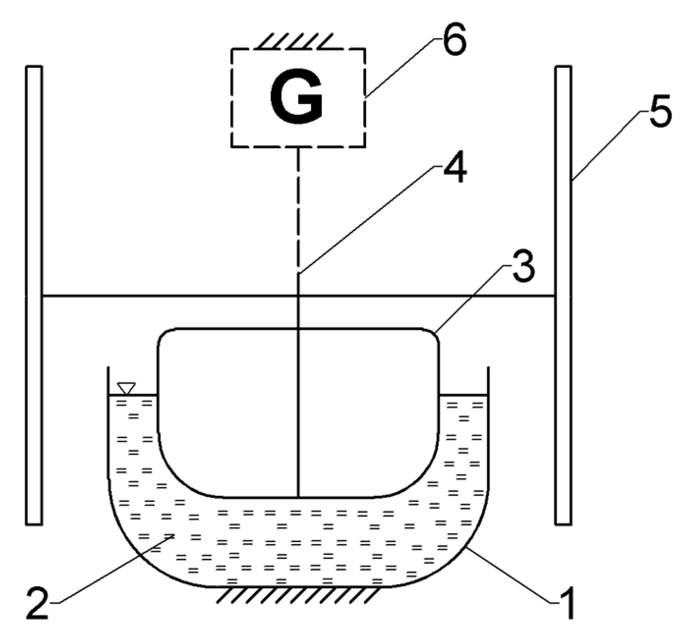
The problem of the impact of excessive loads on the bearing and unstable energy efficiency on the bearing of the wind turbine shaft was addressed by developing a prototype of a new “floating” wind turbine with a vertical axis, in which the vertical load on the shaft is transferred by the buoyancy force of the fluid [31]. So far, the efficiency as well as the critical control, design, and optimization parameters of the proposed solution have not been fully recognized [31]. Figure 1 shows a new type of VAWT called the floating bowl-shaped VAWT.
The main components of the turbine are air or water-bearing supports, blades, main shaft, beam, lower hub assembly, upper hub assembly, generator, brake, and control parts. In the suggested solution, a rotor with a corrosion-resistant bearing surface requires at least three air or water bearings, along with electrical energy-generating components located on the rotor’s circumference [31]. As part of the project, numerical calculations (CFD Ansys Fluent) were performed to check the interaction between the wind force and the suggested new wind turbine structure. Three parameters were used to analyse a turbine with different blade shapes: starting time, average power factor, and the standard deviation of aerodynamic force. Output parameters were assessed, including self-starting ability, energy harvesting efficiency, and fatigue characteristics [31].
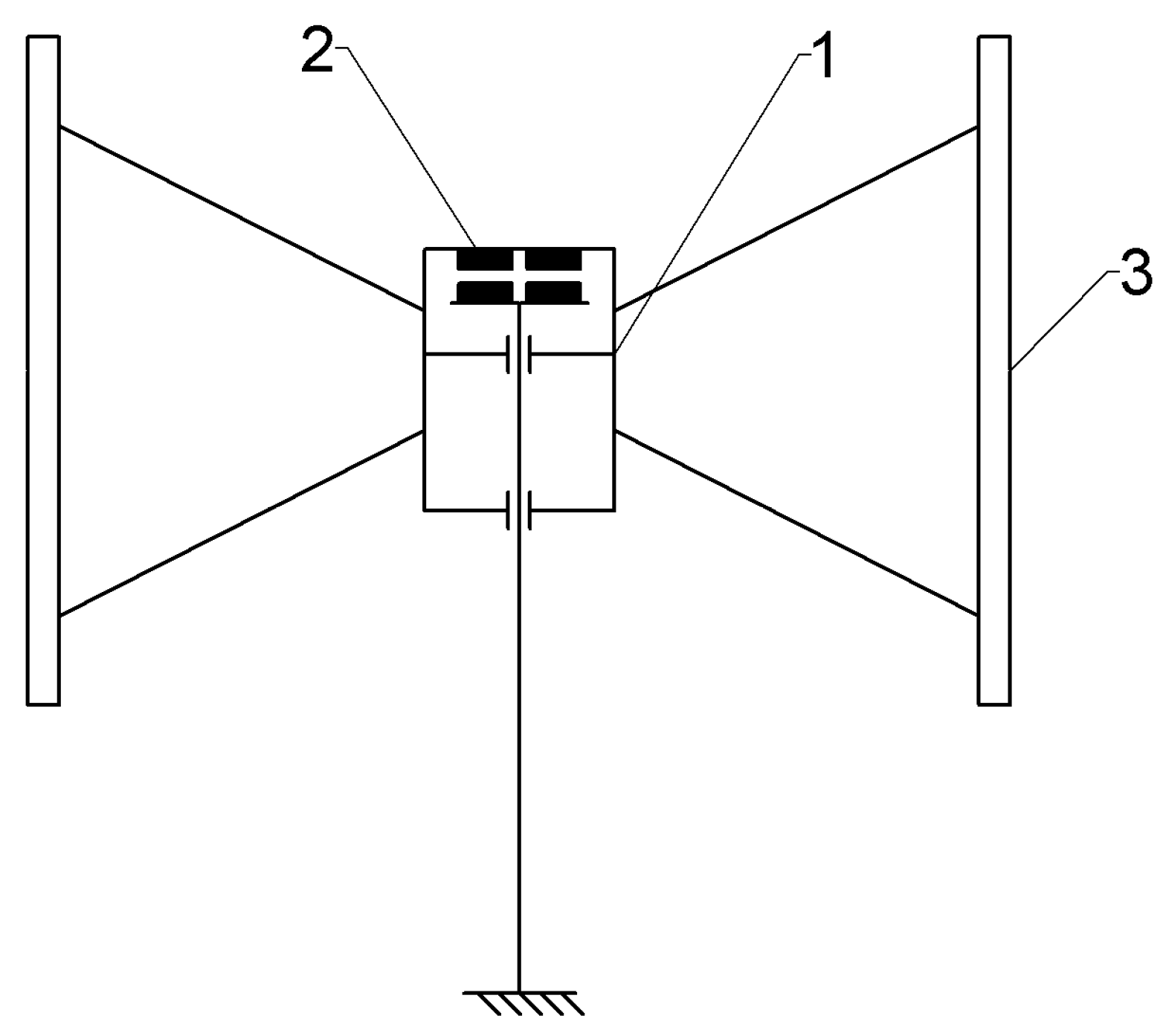
A solution that uses magnetic levitation is another example of reducing the frictional resistance in the vertical shaft-bearing system. The magnetic levitation bearing concept uses neodymium permanent magnets, which virtually eliminate frictional resistance in the main shaft bearings. By reducing resistance to movement, the rotor rotation time increases after the external force stops. This results in increased profitability when using vertical-axis wind turbines [32,33]. Passive magnetic bearings are used in vertical-axis wind turbines to enable “low-wind startup and low-wind power generation” [34], as well as to improve their efficiency [35]. Figure 2 shows a diagram of a levitating VAWT wind turbine mounted on frictionless magnetic bearings. The design parameters were modelled and verified in Solid Works, and the final design was simulated and analysed in Ansys Fluent before a prototype was made [36].
The test results confirm the benefits of using the magnetic frictionless bearing in wind turbines because, with the blade profile used, the VAWT turbine was able to start automatically and produce energy at a wind speed as low as 2 m s−1, which is not typical for Darrieus turbines [36]. However, analysis of the bibliography shows that magnetic frictionless bearings are currently tested and used mainly in wind turbines of low power [37] and with relatively short shaft lengths [38]. Therefore, the need to look for other types of bearings for the main shaft of a wind turbine is justified. For example, the operational properties of a bearing using alternative lubricants containing magnetic nanoparticles were tested. The bearings with grease containing admixtures of magnetic nanoparticles showed reduced vibration speed and acceleration, both under unloaded conditions and after being subject to mechanical load [39].
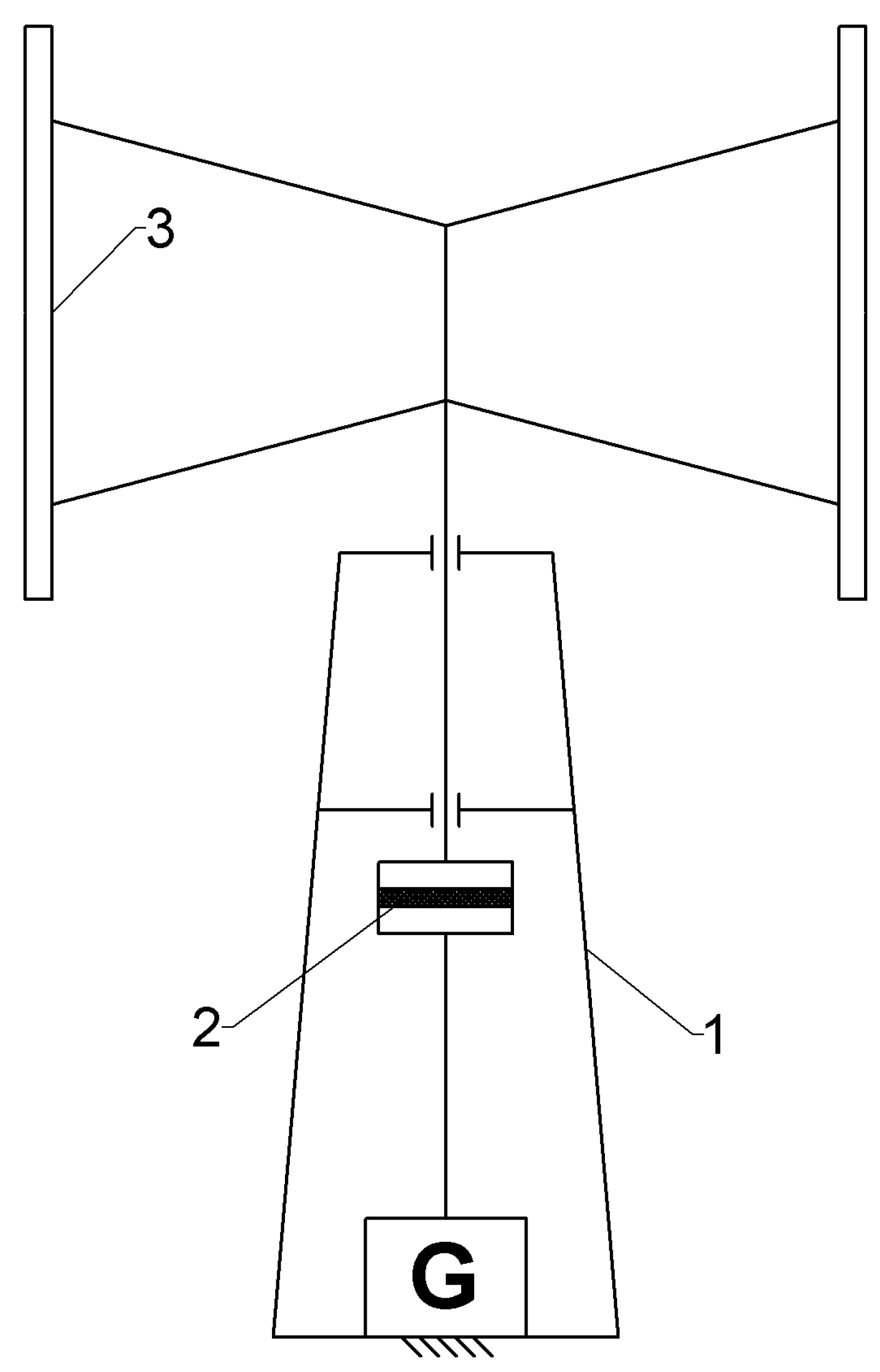
Figure 3 shows an example of a solution of the invention [40], in which the main bearings were relieved by using permanent magnets. A pair of permanent magnets is placed in the upper part of the main shaft, contributing to reducing the pressure of the longitudinal force on the rolling bearings supporting the main shaft.
The patent [41] describes a solution (Figure 4) that minimizes the problems in difficult starting and braking thanks to using the friction clutch and brake, as well as a gear that increases the speed.
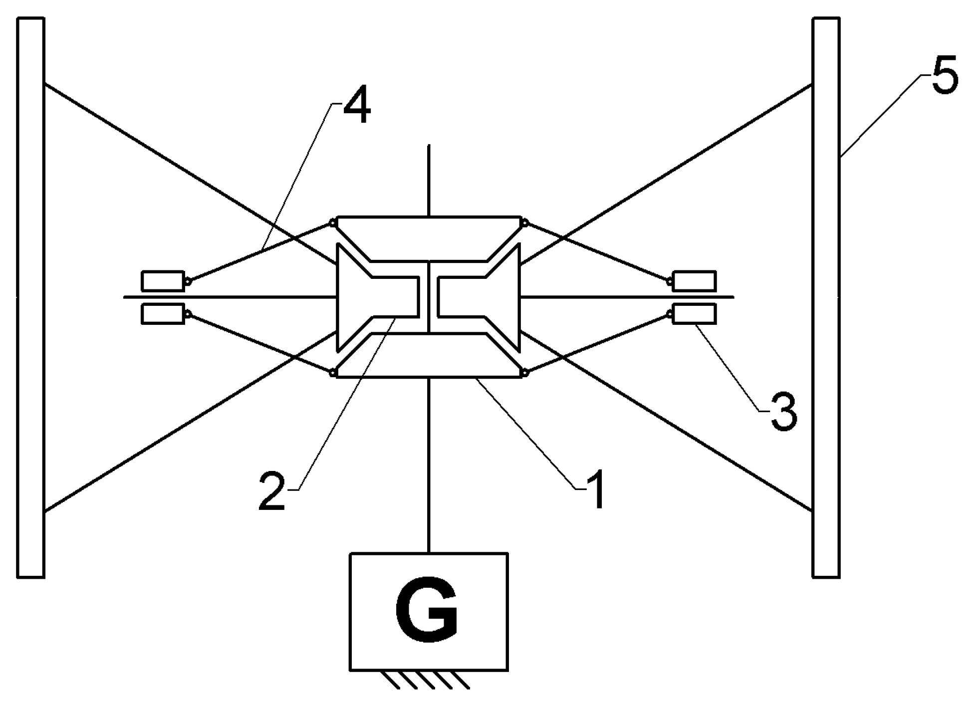
It is similar in the case of patent [42] shown in Figure 5, where the clutch located between the turbine shaft and the generator facilitates starting the turbine in low wind conditions.
Figure 6 shows a solution in the invention [43], which is also equipped with a clutch to facilitate starting and braking but additionally has a two-stage gearbox between the main shaft and the generator.
The invention [44] also uses a clutch, but as a safety release allowing the rotor to rotate freely when the wind is too strong. However, the invention [45] uses multiple bearings, the purpose of which is to significantly relieve the main bearings of the turbine shaft and to stabilize the structure in variable wind conditions. Additional bearings for guiding the rotor track are placed on the rotor periphery in its lower part.
Plain bearings are much more durable and quiet compared to rolling bearings. Unfortunately, they are rarely used in wind turbines as main shaft bearings, as their correct operation requires a specific rotational speed at which a lubricating film is formed. The lack of a lubricant film in the plain bearing causes high friction resistance and thus makes it difficult to set the turbine shaft in motion. Frictional resistance appears in the slide bearing during the starting and stopping phases of the turbine shaft. Figure 7 shows the invention [46], which uses a plain bearing for the turbine main shaft.
The bearing is constantly lubricated with oil from a tank located directly next to the plain bearing.
The presented selected technical solutions contribute to relieving the bearing of the main shaft of a wind turbine and reducing the resistance to motion during the turbine startup and demonstrate a great interest in this issue among the researchers and designers of VAWT power plants. Therefore, our two proposed technical solutions for the use of an innovative hybrid bearing are fully in line with the current state of the art in this developing segment of wind energy.

3. Hybrid Wind Turbine Shaft-Bearing System

The use of a special trust-transverse plain bearing, supported by rolling supports during start-up and run-down of the wind turbine shaft, could be a solution to the presented problem [29]. The essence of the solution is that in the starting and stopping phases of the wind turbine shaft, the shaft load is transferred by the rolling bearing, and in the nominal speed range by the plain bearing. This solution allows for low starting resistance of the wind turbine and its quiet operation. The short-term operation of a rolling bearing will also ensure its long-term use.
Below are two conceptual solutions for a hybrid bearing, each differing in the geometric features of the plain bearing.

3.1. Hybrid Bearing with a Conical Shape of a Journal

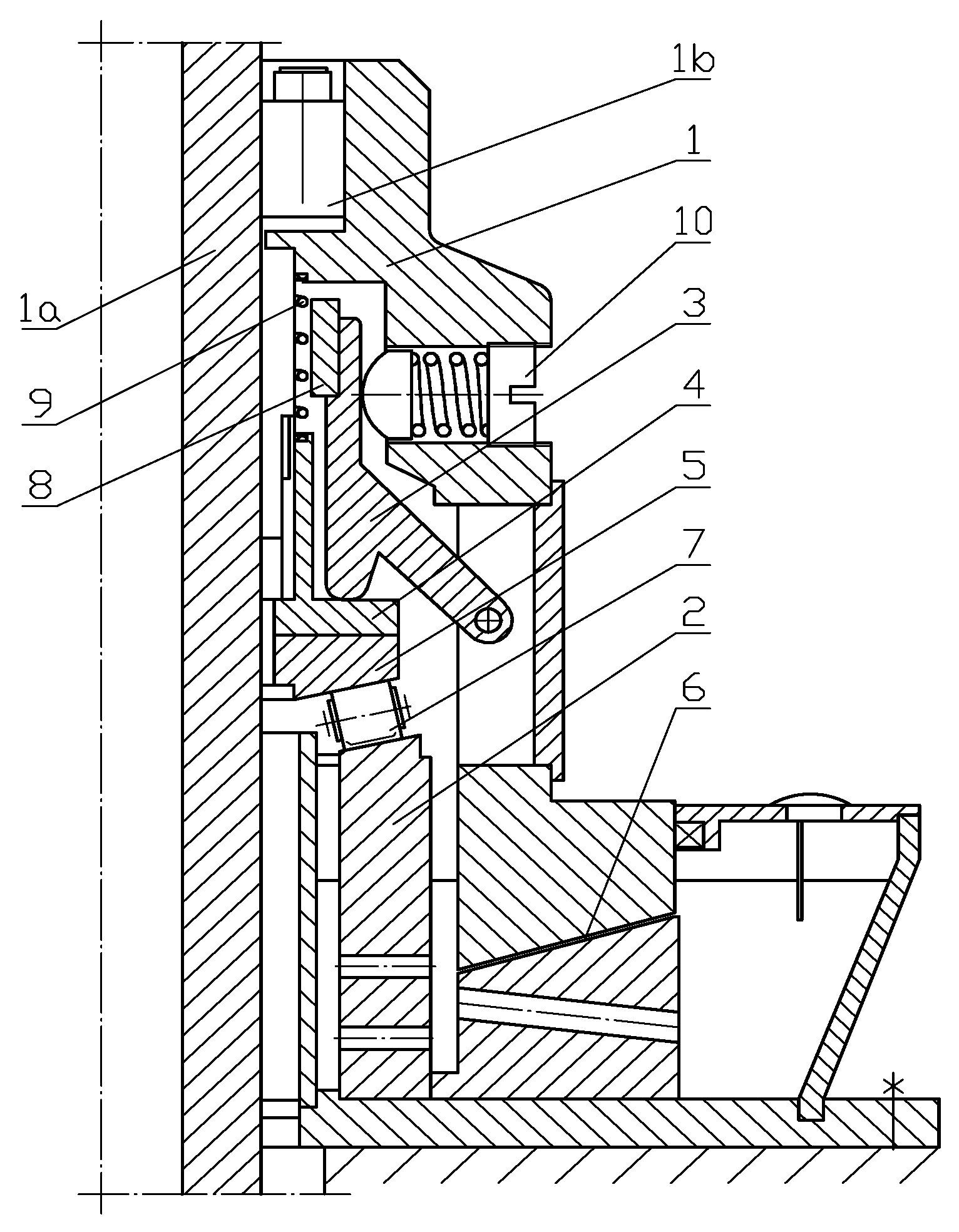
A conceptual solution of the bearing system for a wind turbine shaft with a vertical axis of rotation, consisting of a rolling bearing and a plain bearing with a conical journal shape, is shown in Figure 8.
The main shaft of the wind turbine (1a), coupled with the upper enclosure of the plain bearing (1), is mounted on two bearings: a rolling bearing (7) and a plain bearing (6). Both bearings rest on a fixed base (2). Before starting the wind turbine, while it is not in operation, the bearing node is initially adjusted to relieve the plain bearing. Using the adjusting screw (10), the lever (3) and the intermediate element (4), causes exerting pressure on the upper part of the rolling bearing raceway (5). The turbine shaft is lifted and, at the same time, the load is added to the rolling bearing (7) and the plain bearing (6) is relieved, as a lubrication gap is created between the conical sliding surfaces of the bearing (6). Therefore, only the rolling bearing (7) works when starting the turbine. As the rotational speed of the turbine shaft increases, as a result of the centrifugal force acting on the lever (3) with a large inertial weight (8), the pressure of the lever (3) on the upper part of the rolling bearing raceway (5) decreases. This part is pulled up by the spring (9), relieving the load on the intermediate element (4) and the rolling bearing itself (7). At the same time, the main shaft of the turbine (1a) lowers, adding load to the slide bearing, in which, due to the shaft rotational speed, there are conditions to create a lubricant film necessary for the proper operation of the plain bearing (6).
During the free run of the turbine until it stops, the reverse process takes place—the pressure of the lever (3) on the intermediate element (4) and the upper part of the raceway (5) of the rolling bearing (7) increases, and the height of the lubrication gap on the slide bearing (6) increases. At a sufficiently low rotational speed of the turbine shaft, the entire load is taken by the rolling bearing (7). As a result, during the start-up and free run of the turbine, the rolling bearing operates, and during the nominal speed of the turbine, the plain bearing operates.
Based on the hybrid bearing concept presented in Figure 8, its structural form was designed. Using the catalogue card of one of the commercials [13], its weight was determined. It was assumed that the total weight of rotating components (turbine, shaft, and rotating bearing components) is 200 kg. On this basis, each component of the hybrid bearing was modelled (Figure 9), standard and catalogue parts were selected (rolling bearing, springs, coupling bushing, screws, pins, etc.), and the strength of each component and pressure on the contact surfaces of the cooperating components were verified. The hybrid bearing model, developed using the Inventor program, is shown in Figure 9.
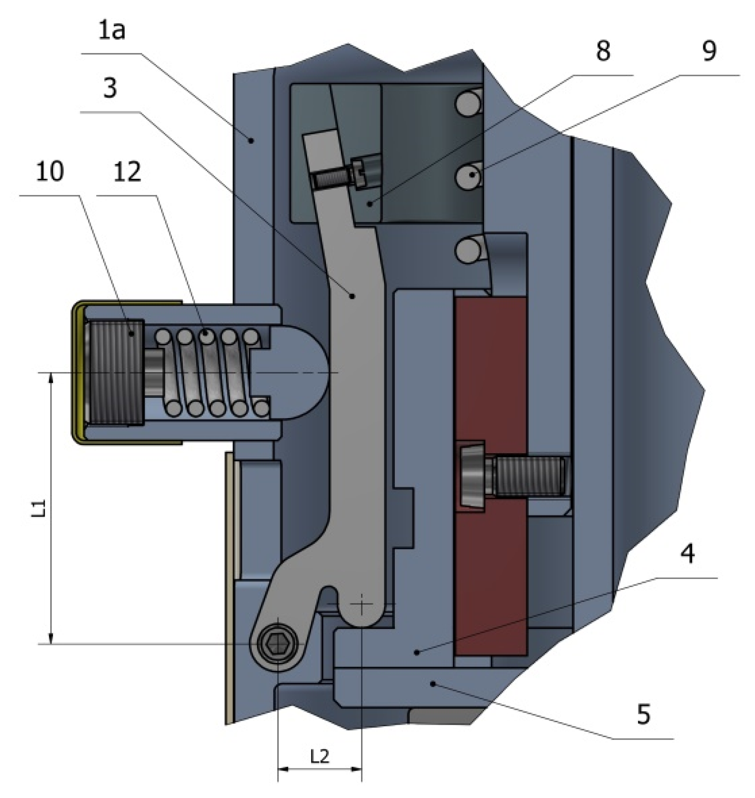
Determining the mass of inertial weights (8) and levers (3) (see Figure 10) in the mechanism of automatic load switching between the rolling and plain bearings, when changing the rotational speed of the turbine shaft, is one of the most important issues affecting the functionality of the hybrid bearing.
The mechanism for automatic switching load between a rolling and a plain bearing consists of three identical levers (3) arranged symmetrically around the shaft. When the wind turbine is standstill, the resultant pressure force of the lever (3) on the intermediate element (4) of the roller bearing raceway balances the total mass of the rotating parts of the wind turbine and, thanks to a lubrication gap between the pan and the journal of the plain bearing, relieves it.
The boundary speed of shaft rotation n0 at which the load is switched from a rolling bearing to a plain bearing depends on the mass of the lever with inertial weights and the force in the pressure spring.

3.2. Hybrid Bearing of the Spherical Shape of a Journal

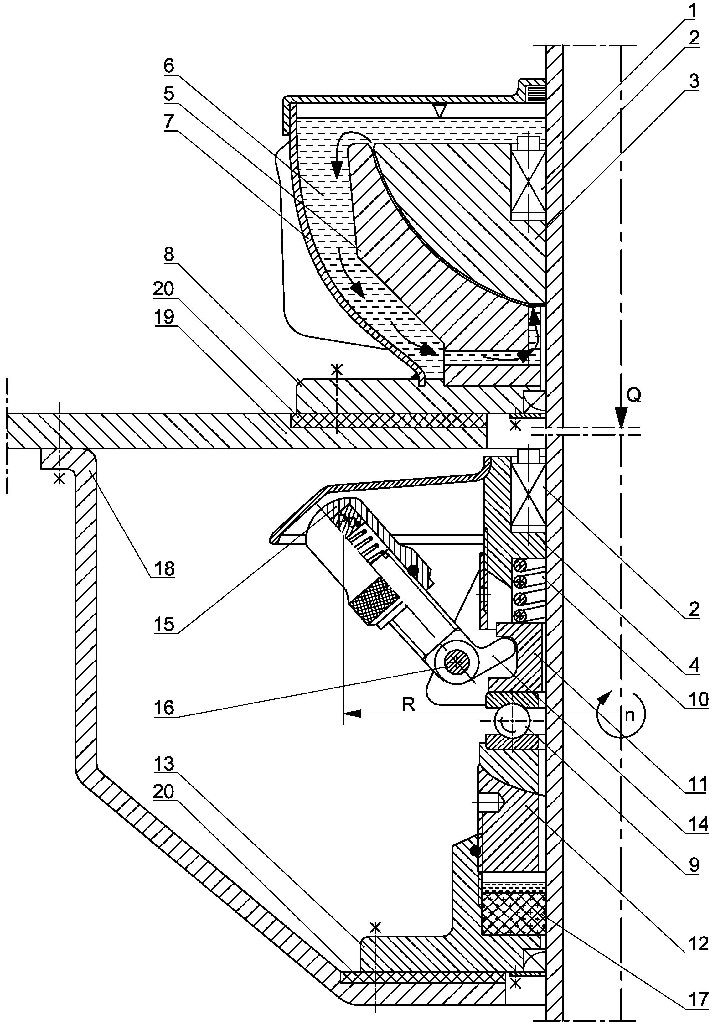
Another example of a hybrid bearing whose start-up and free run until the turbine stops are assisted by a rolling support is shown in Figure 11.
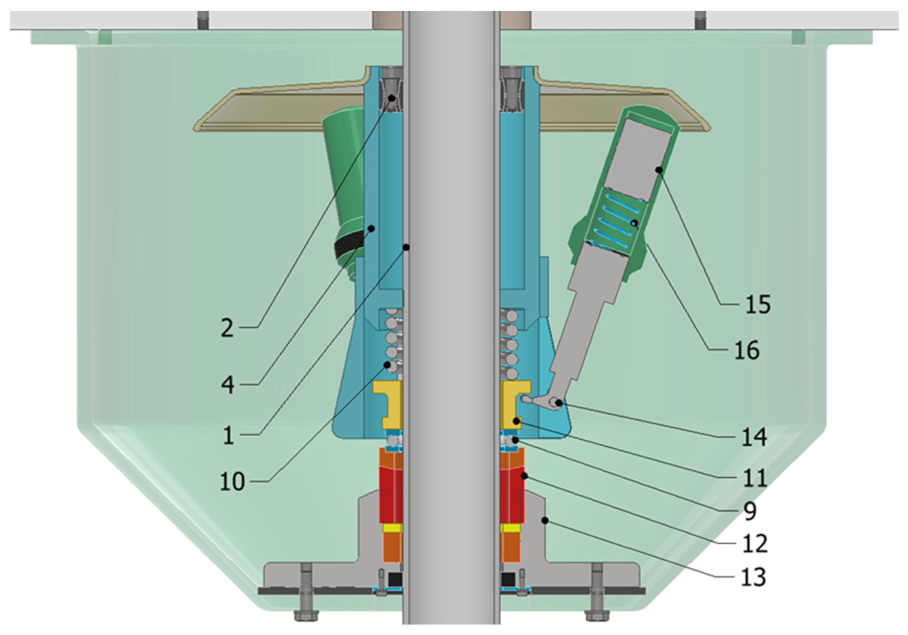
The spherical journal of the plain bearing (3) and the supporting sleeve (4) of the automatic bearing load-switching mechanism are mounted with expansion rings (2) on the vertical tubular shaft (1) of the turbine. The stationary bushing (5) of the plain bearing is immersed in the lubricating liquid (6), filling the enclosure (7) mounted in the base of the plain bearing (8).
During standstill and in the initial phase of starting the turbine, the axial load on the shaft (1) is transferred by the assisting trust plain bearing (9) through the pressing spring (10) and the moving sleeve (11). The bearing rests on an adjusting sleeve (12), which is screwed to the base (13).
The mechanism of automatic load switching between the plain bearing and the rolling bearing is made up of at least three levers (14) of inertial weights (15), evenly distributed around the circumference of the sliding sleeve (11) and mounted on the axles (16). The lever (14) is in contact with the sliding sleeve (11) at one end.
Before starting up the bearing system, a condition in which there is a small lubrication gap between a journal (3) and a pan (5) should be fulfilled by turning the adjusting sleeve (12). After starting the wind turbine, when the axial load of the shaft is transferred only by the assisting plain bearing (9), due to the increasing rotational speed of the shaft and action of the centrifugal forces on the inertial weights (15), the sliding bushing (11) is gradually lifted. As a result, the assisting rolling bearing (9) is smoothly relieved. Its load is gradually taken over by the plain bearing, in which, as a result of the slipping of the spherical journal (3) against the pan (5), a lubricant film is created, ensuring full hydrodynamic lubrication. During the transition period, both bearings work for a short time with a smoothly changing proportion of the transferred load. When the required rotational speed of the wind turbine shaft is reached, the trust plain bearing (9) stops and the full load is transferred smoothly by the liquid-lubricated slide bearing. The spherical-shaped journal of the plain bearing (3) effectively transfers the full axial load of shaft Q and the transverse load resulting from the wind pressure on the wind turbine rotor.
Transverse stabilization of the turbine shaft is provided by a self-lubricating plain bearing (17). It transfers only small transverse forces that may occur in the system. Together with the base (13), it is attached to a console (18) suspended from the building’s ceiling (19). Damping underlays (20) eliminate possible vibrations in the system and dampen noise.
If the rotational speed of the wind turbine shaft decreases, e.g., during free run, the automatic bearing load switching mechanism causes the axial load of the shaft to be gradually taken over by the assisting rolling bearing (9). When the wind turbine stops, the total axial load on the shaft is transferred only by the trust plain bearing. The plain bearing therefore always only operates under full liquid lubrication. The rotational speed at which the load is switched can be adjusted within a wide range by changing the mass of the inertial weights (16). Then, characteristics of the automatic load switching mechanism between the rolling bearing supporting start-up and running and the main plain bearing operating at nominal wind speed conditions change.
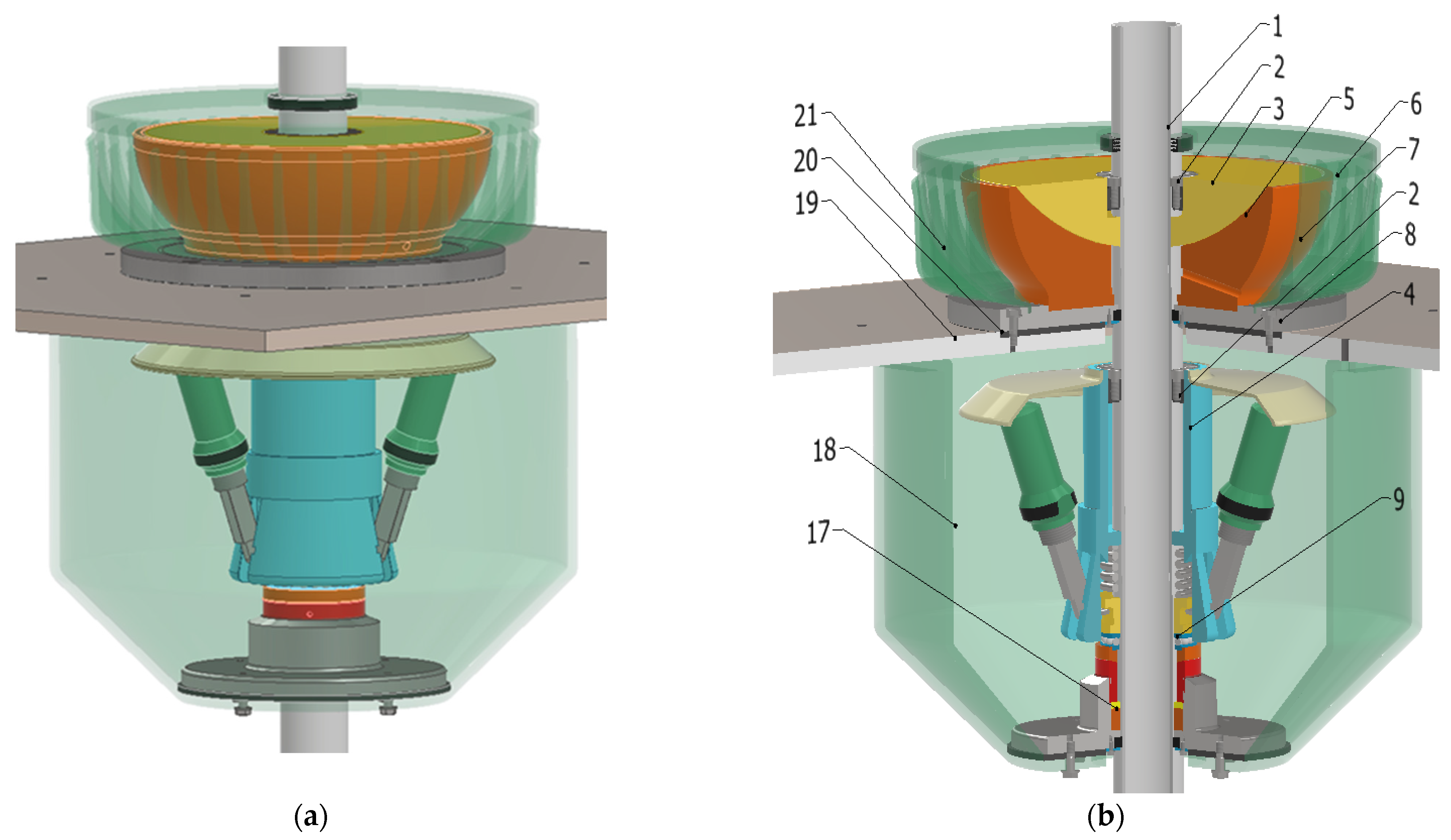
The design form of the bearing with a spherical journal was developed using the Inventor program. Basic data regarding the parameters of the wind turbine, in particular its weight and shaft weight, were taken from the catalogue card [13], as in the case of a bearing with a conical journal shape. After the initial design of the hybrid bearing components, the mass of the journal and inertial weights were determined and basic strengths were calculated. On this basis, it was assumed that the total weight of the turbine, shaft, and rotating components of the bearing was 2020 N. Figure 12 shows a view and a cross-section in one-quarter of a hybrid bearing model with a spherical journal.
Both the modelled shape and the relatively large dimensions of the plain bearing (journal and pan) give measurable operational benefits. The spherical shape of the journal and bearing pan enables transferring the large longitudinal forces and transverse loads during the wind turbine operation. Modelling the journal and pan of the sliding bearing with large dimensions led to a high average sliding speed and a significant reduction in the bearing contact pressure. Grooves were also modelled on the spherical surface of the journal, acting in a way analogous to the blades of a centrifugal pump. During the rotation of the plain bearing, the grooves increase the circulation of the lubricating fluid (6) around the journal. In addition to its relatively thin walls, the enclosure (7) of the plain bearing has additional ribs (21) designed to facilitate the cooling of the lubricating liquid which flows through the gap between the spherical journal (3) and the sleeve (5), and absorbs the heat generated in the bearing.
The mechanism of automatically switching the load to the bearing has a significant impact on the functionality of the wind turbine shaft-bearing system. A cross-section of this mechanism is shown in Figure 13.
The supporting sleeve (4) is the element rigidly mounted on the wind turbine shaft (1). When the wind turbine is not operating, the vertical load on the turbine shaft is transferred to the thrust bearing (9) through the sliding sleeve (11) and the compression spring (10) attached with the other end to the supporting sleeve (4). Parameters of the compression spring (10) were selected taking into account the assumed total weight Q of the shaft, turbine, and rotating bearing components. The plain bearing is then completely relieved of the load due to the small lubrication gap between the ball journal (3) and the sleeve (5). This facilitates the start-up of the wind turbine because, in the bearing node, there are only resistances to movement in the rolling bearing (9).
During the rotational movement of the wind turbine, the levers of the inertial weights (14) compress the pressing spring (10) and reduce the height of the lubrication gap between the bushing and the journal of the slide bearing—also rigidly mounted on the turbine shaft. For each of the three inertial weights (15), a compressing spring (16) was selected with the same parameters, such as stiffness, wire diameter, total number of turns, nominal load and length of the relieved spring. The task of the pressure springs (16) is to keep the inertial weights (15) in the extreme position to increase the centrifugal force acting on the levers (14) during the bearing rotation. If the rotational speed of the motor shaft (1) is higher than the speed at which the plain bearing obtains its nominal load capacity, the operation of the inertial weight levers (14) will result in lifting the sliding sleeve (11) and relieving the thrust roller bearing (9).

4. Equation Formulation

The functionality of a hybrid bearing—especially its durability and movement resistance—largely depends on boundary speed shaft rotation n0, at which the total axial load is taken over by the plain bearing. Analytical relationships and computational algorithms enabling determining the boundary speed of shaft rotation n0 are presented below.

4.1. Estimation of Boundary Rotation Speed of Hybrid Bearing with a Conical Journal

Calculations of the boundary rotation speed n0 at which the total load to the turbine shaft is taken over by the plain bearing were made without considering the impact of the load capacity of the plain bearing on the balance of the mechanism for switching the load to bearings.
The load diagram of the lever of the bearing load switching mechanism in the case of a standstill wind turbine is shown in Figure 14.
A single lever is loaded with the following forces: F1—force in the pressing spring (12), F2—reaction of the intermediate element (4) and the total weight G0 of the lever (3) and the inertial weight (8). If the wind turbine shaft is not operating, the total weight of the shaft and rotating components of the turbine is transferred only by the rolling bearing. Therefore, the resultant reaction F2 balances the weight of the rotating components with a mass of m. Hence, the reaction F2 is the following:
F 2 = m · g 3
The force F1 in the pressure spring was determined, taking into account the total mass m0 of the lever and the inertial weight, as well as geometric features of the lever of the mechanism for switching the load to bearings—L1, L2, and L4—which are marked in Figure 14.
F 1 = 1 3 m · L 2 m 0 · L 4 · g L 1
It was assumed that after the turbine reaches a rotational speed close to the boundary speed, the levers (3) should deflect, which will relieve the rolling bearing and the weight of the rotating parts of the turbine-bearing system will be transferred only by the plain bearing.
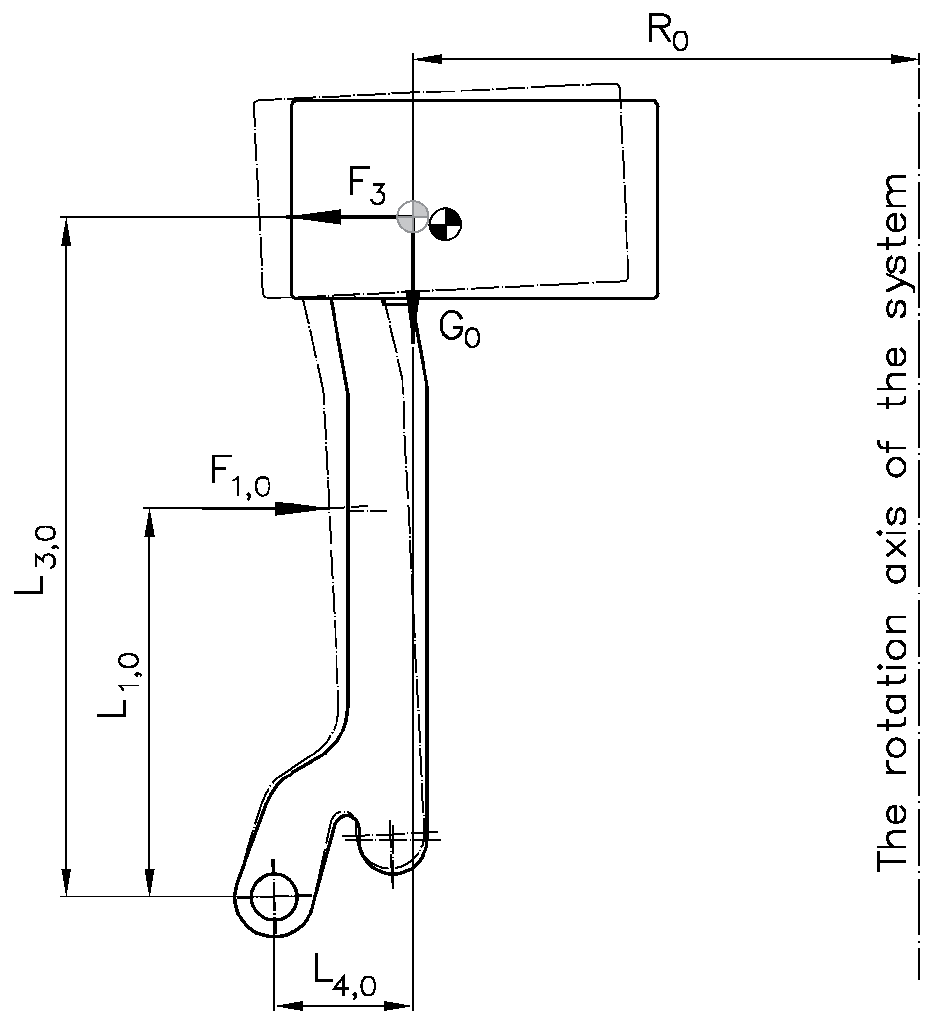
After the roller bearing is relieved, the lever remains in balance due to the force in the compression spring, the weight of the lever, and the centrifugal force caused by the rotation of the turbine shaft. The system of forces acting on the lever after the rolling bearing is relieved is shown in Figure 15.
The centrifugal force F3 acting on the lever was determined from the following formula:
F 3 = m 0 · ω 0 2 · R 0
where:
  • m0—weight of the lever,
  • ω0—boundary angular speed of the turbine shaft,
  • R0—distance of the centre of mass of the lever from the axis of rotation.
The following relationship results from the condition of equilibrium of the forces system presented in Figure 15:
ω 0 = F 1,0 · L 1,0 + m 0 · g · L 4,0 m 0 · R 0 · L 3,0
Thus, the boundary rotation speed of the wind turbine shaft n0 depends on the weight m0 of the lever and its geometric features and force F1,0 in the pressing spring.

4.2. Kinematic Model of the Automatic Bearing Load Switching Mechanism

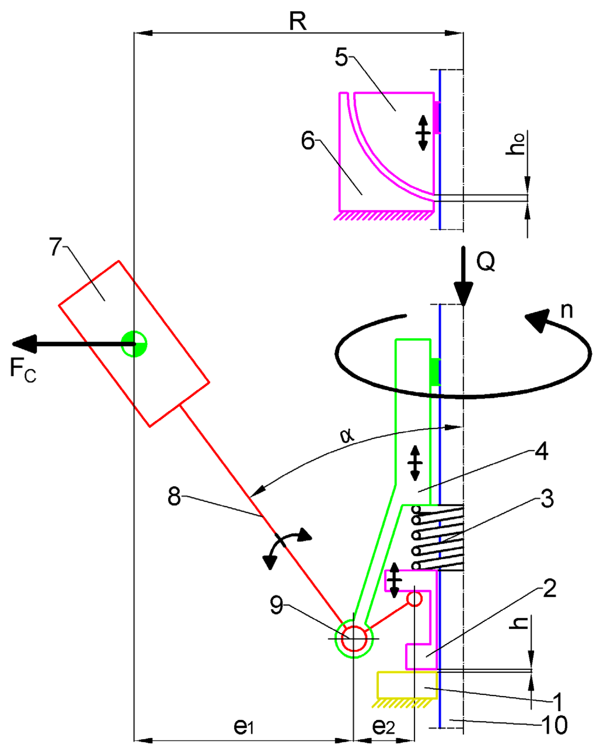
To verify the design assumptions of the automatic bearing load switching mechanism, an adequate kinematic simulation model of this mechanism was created, based on the kinematic diagram shown in Figure 16.
Kinematic analysis of the model mechanism was performed by distinguishing four operating states. The first operating state of the mechanism is preparatory work. This state is characterized by a lack of rotational speed in the wind turbine and when the wind turbine is given to operate. In the preparatory work state, the automatic load-switching mechanism of the bearings is only affected by the static load caused by the weight (Q) of the wind turbine and the components of the hybrid bearing firmly attached to the turbine shaft. The load (Q) exerts pressure through the supporting sleeve (4) on the compressing spring (3), which, by bending, reduces the height of the lubrication gap (h0). As a result, the deflection of the compression spring (3) causes the lever (8) to deflect from the vertical axis of the bearing, increasing the angle (α). The preparatory work ends when the assumed lubrication gap height (h0) of 5 mm is achieved.
Static operation is the second distinguished operating state of the mechanism for automatic switching of the load to bearings. In a static operation state, the shaft of the wind turbine does not rotate. In this operating state, the height of the lubrication gap (h0) is maintained at the assumed constant value resulting from the adjustment made in the preparatory operating state. The entire vertical load to the wind turbine is transferred through the supporting sleeve (4) to the compressing spring (3) and then to the sliding sleeve (2) and the thrust roller bearing.
Changeable operation is the third distinguished operating state of the mechanism for automatically switching the load to bearings. The changeable operation state is when the rotational speed of the wind turbine shaft varies in time. In this operating state of the mechanism, as a result of setting the inertial mass (7) in rotation, a centrifugal force (FC) is generated at the radius of rotation (R). The magnitude of the force depends on the rotational speed of the wind turbine (n) and the angular position of the lever (8). The lever mechanism, characterized by the radii of action (e1, e2), causes multiplication of the effect of the lever (8) on the sliding sleeve (2) compared to the centrifugal force (FC). As a result, increasing centrifugal force (FC) further reduces the height of the lubrication gap (h0) until the plain bearing (5,6) achieves the load capacity required to take over the vertical load to the wind turbine. After the plain bearing has achieved the required load capacity, further operation of the mechanism causes the thrust rolling bearing (1) to be relieved, and the sliding sleeve (2) to move and to increase the gap (h) between the thrust rolling bearing and the sliding sleeve.
Extreme operation is the fourth operating state of the mechanism. It is characterized by obtaining a lever radius (e2) close to zero and a lever angle (8) from the vertical axis close to 90°. As a result of such a lever position (8), the sliding sleeve (2) is moved away from the longitudinal roller-bearing raceway as much as possible. The shaft rotational speed in the extreme operating state was defined as the operating limit speed of the mechanism for automatically switching the load to bearings. Further increasing the rotational speed of the wind turbine shaft above the limit no longer changes the position of the lever (8) and the gap height (h).
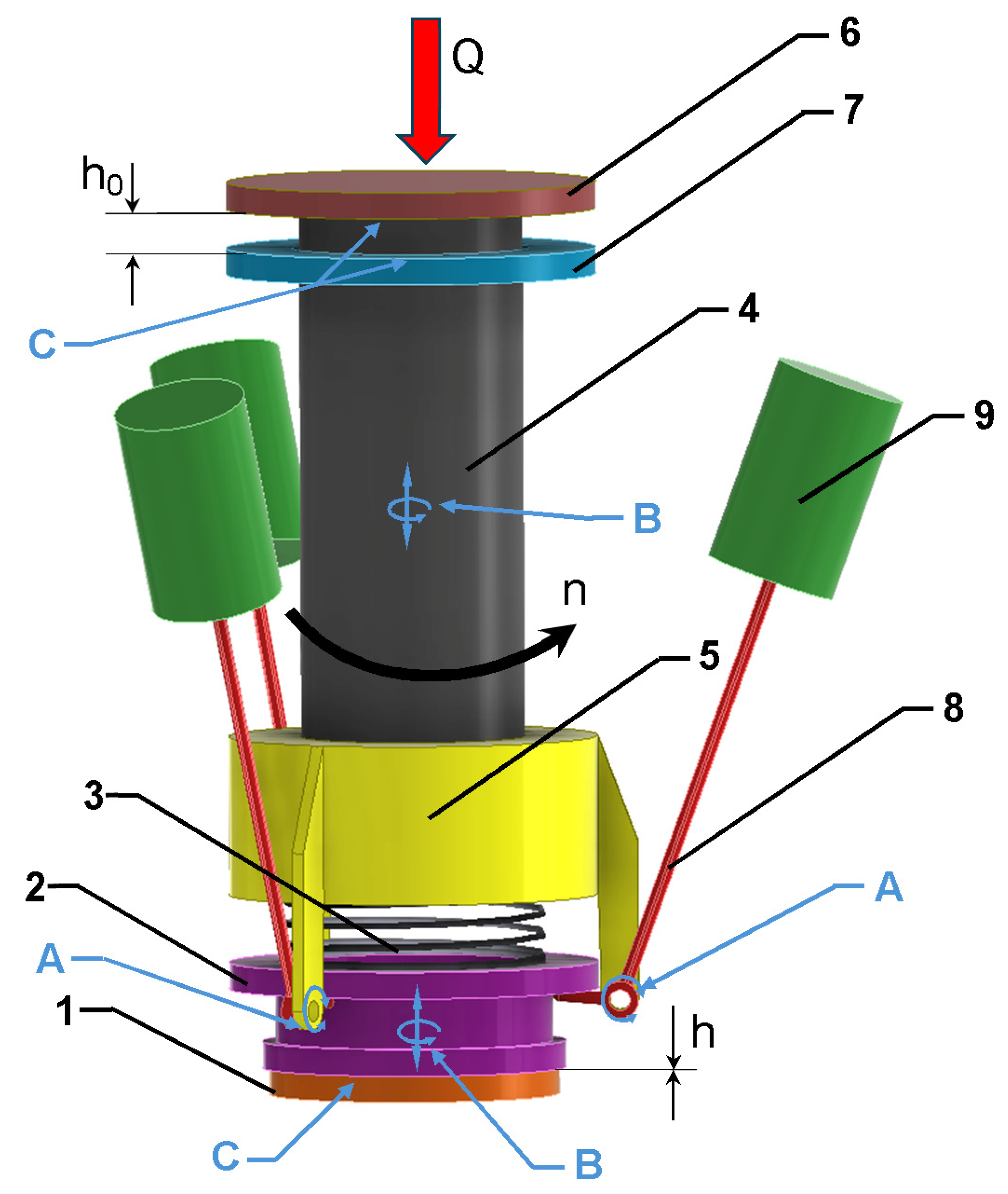
To simulate the operation of the automatic mechanism for switching the load to bearings, a simulation model was built based on the kinematic diagram shown in Figure 16. A model simulating the operation of the mechanism was created in the Autodesk Inventor—Dynamic Simulation software environment. Figure 17 shows a solid model used to simulate the operation of the automatic mechanism for switching the load to bearings. The main component of the simulation model is the tubular shaft (4) with the supporting sleeve (5) and the ball-bearing journal (6). In the simulation, this element has two degrees of freedom (B). It can rotate around the axis of the wind turbine shaft and is free to move along this axis. In the simulation, this element is set to a rotational speed corresponding to the rotational speed of the wind turbine (n).
To check changes in the height of the lubrication gap (h0), an element of a fixed ring (7) was created in the simulation model, which replaces the plain bearing shell. To detect the contact between this pair of elements, a 3D contact connection was used on their surfaces (C).
In the lower part of the wind turbine shaft, where there is a supporting sleeve (5), inertial masses (9) are mounted rotatably (A) on levers (8). As a result of rotation at speed (n), centrifugal forces act on the inertial masses (9) and move the sliding sleeve (2) through the lever mechanism. As a result, the sliding sleeve (2) acts on the supporting sleeve (4) through the flexible connection (3). Due to the required contact of the lever tip (8) with the contact surface of the sliding sleeve (2), a 3D contact connection (C) was created on these elements. To measure the height of the gap (h) between the sliding sleeve (2) and the fixed raceway of the thrust bearing, a 3D (C) contact connection was created between the elements.

4.3. Estimation of Technical Parameters of a Plain Bearing with a Spherical Journal Shape

Plain bearing is a component of the hybrid bearing that transmits the axial load of the wind turbine shaft. Due to the spherical shape of the journal and bush, analytically determining its load capacity is a complex problem. Since the design of the bearing was developed using the Inventor software package, the Finite Element Method seems to be a natural method for solving this problem. However, determining the bearing load capacity using this method seriously complicates the task of modelling the interaction of the journal and bearing with the oil layer filling the lubrication gap, using the Fluid–Structure Interaction (FSI) module. Modelling the pressure distribution in a lubrication gap, with a height of hundredths of a millimetre, requires the creation of at least several layers of Euler cells. This results in the adoption of a very dense mesh, both in the model of the fluid filling the lubrication gap, as well as in the finite element mesh of the journal and bush models. As a consequence, the created MES-FSI model will be described by a huge number of equations, which generates problems with the convergence of the task and significantly extends the computation time.
Taking the above into account, it was decided that at the current, initial stage of developing the concept of a hybrid bearing with a spherical journal shape, the MES-FSI method would not be used, and the technical parameters of the plain bearing would be estimated using simpler analytical methods used in the Basics of Machines Designing.
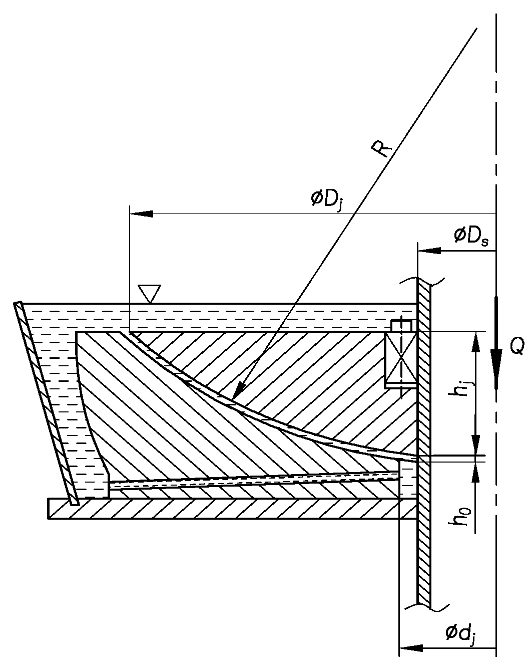
The design of the bearing is shown schematically in Figure 18.
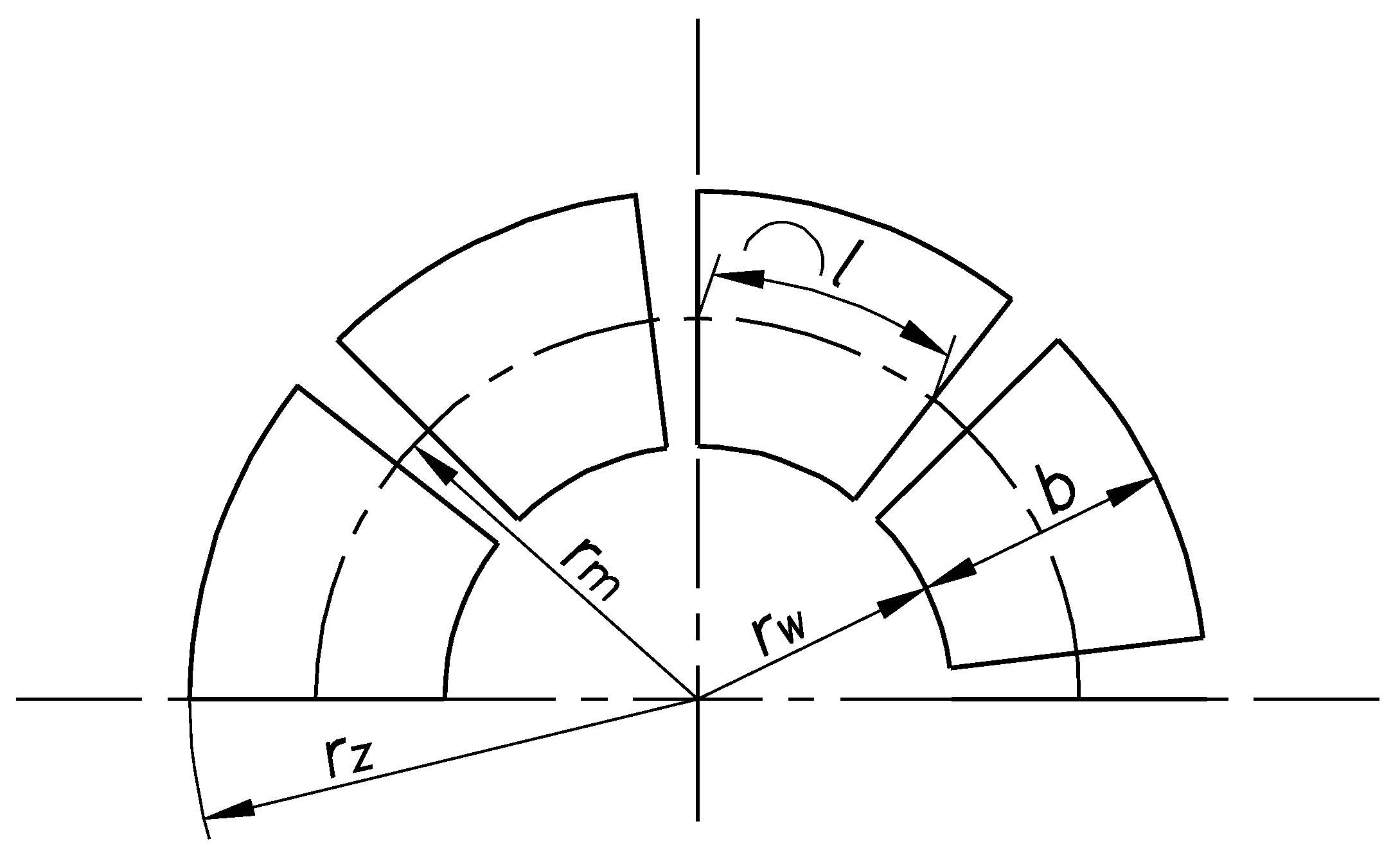
The spherical shape of the cooperating surfaces of the journal and bushing makes the analytical description of the dynamic oil pressure distribution in the lubrication gap very difficult and requires the adoption of a number of simplifying assumptions, the validity of which will have to be verified experimentally. Therefore, at the current preliminary stage of tests, using the examples of longitudinal plain bearings described in the literature [47], an equivalent longitudinal segment bearing with overall dimensions shown in Figure 19 was adopted for calculations.
In calculations checking the equivalent segment bearing, the following simplifying assumptions were made:
  • The considered hybrid bearing node of the wind turbine shaft is located in a closed room. The ambient temperature of the bearing node ranges from +15 °C to +40 °C.
  • The rotation speed of the turbine shaft is equal to the boundary speed n0. Therefore, the plain bearing transmits the total axial load of the shaft.
  • Criterion of the load-bearing capacity of the plain bearing is met [47]:
K = p ¯ · h 0 2 η · υ · b < K m a x = 0.069
where:
  • K—the dimensionless load capacity index,
  • h0—the height of the lubricating gap,
  • η—dynamic viscosity coefficient,
  • b—segment width,
  • υ—average peripheral speed of the shaft journal.
The purpose of the calculations is to check whether the segment bearing with technical parameters selected in accordance with condition (5) also meets the conditions of accepted surface pressure and non-heating of the bearing. The calculation process is as follows:
  • Selection of geometric parameters of an equivalent segment bearing.
    It was assumed that the internal radius rw of the segment bearing meets the following condition (see Figure 18):
    r w = 0.5 · d j
    According to [47], a number of the bearing segments z and geometric parameters presented in Figure 19 depend on the radius rw.
r z = z + 0.8 · π z 0.8 · π
r m = 0.5 · r w + r z
b = l = r z r w
2.
Determination of oil parameters, such as oil density, the kinematic viscosity coefficient, the dynamic viscosity coefficient, and the specific heat of oil.
3.
Determination of the average peripheral speed of the shaft journal from the formula
υ = r m · π · n 0 30
where:
  • rm—average radius,
  • n0—boundary rotation speed of the turbine shaft.
4.
Determination of average pressure in an equivalent plain bearing from the formula:
p ¯ = Q A = Q z · b · l
5.
Determination of the lubrication gap height h0 from the following formula:
h 0 = K m a x · η · υ · b p ¯
where:
  • Kmax—maximum value of the criterion for the bearing load capacity,
  • η—dynamic viscosity coefficient,
  • υ—average peripheral speed of the shaft journal,
  • b—segment width.
6.
Determination of the friction torque—Pf generated in the bearing:
P f = μ · Q ·   υ
where:
  • υ—average peripheral speed of the shaft journal,
  • Q—shaft axial load,
  • μ—friction coefficient
μ = 3 · η · υ p ¯ · b
7.
Checking the following conditions:
Condition of permissible surface pressure in a bearing
p ¯ < k 0
where:
  • k0—permissible pressure.
Condition of non-heating of the bearing
p ¯ · υ < p ¯ · υ r e q = 1 M N m · s
Not meeting conditions (13) or (14) requires correction of the bearing geometrical parameters or oil parameters.

5. Results

5.1. Boundary Rotation Speed of Hybrid Bearing with a Conical Journal

The following forces act on the mechanism for switching the load to bearings: the weight of the lever with an inertial load, centrifugal force, and the force in the pressing spring. Table 2 contains the parameters required for the determination of force F1 in the pressing spring when the turbine shaft is standstill.
If the speed of the turbine shaft is close to the boundary speed n0, the levers (3) deflected under the impact of centrifugal force will relieve the rolling bearing. It was assumed that moving the lever (3) away from the intermediate element (4) by 1 mm is sufficient to completely relieve the rolling bearing. It was assumed that the initial lubrication gap in the plain bearing is several tenths of mm.
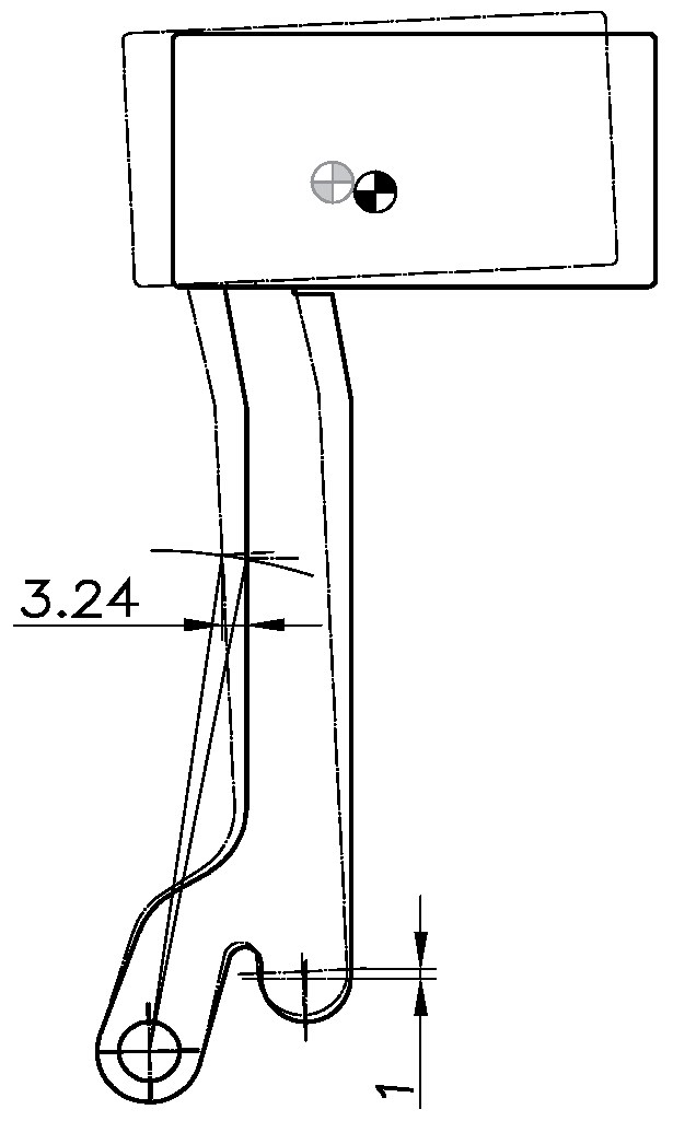
Raising the point of contact between the lever (3) and the intermediate element (4) and pressing the raceway (5) of the rolling bearing by 1 mm will result in increased deflection of the spring (12). As the results from the geometric relationships presented in Figure 20 demonstrate, a lubrication gap of 1 mm above the upper race of the rolling bearing will result in deflection of the contact point of the spring with the loading lever by 3.24 mm. The characteristics of the selected spring show that such a deflection causes a force in a single spring equal to F1,0 = 278 N.
The boundary angular speed of the turbine shaft ω0 is determined from Formula (4). Table 3 gives the parameters necessary to determine the boundary rotation speed n0 at which the total load to the shaft is taken over by the plain bearings.
The nominal rotation speed of the wind turbine shaft, the parameters of which were adopted when developing the hybrid bearing model, is 320 rpm. The rolling bearing while maintaining a lubrication gap of 1 mm between the lever and the upper raceway of the plain bearing will be fully relieved at a rotation speed of approximately 92% of the nominal speed.

5.2. Simulation Results of Operation of the Mechanism for Automatic Switching the Load to Bearings

Simulating the operation of the mechanism for automatically switching the load to bearings requires assuming a few parameters. For a reliable simulation of the operation of the automatic mechanism for switching the load to bearings, it is necessary to properly parameterize the simulation. The values of the adopted parameters are listed in Table 4. Due to the negligible impact of friction on the operation of the mechanism, friction in structural nodes was not included in the simulation.
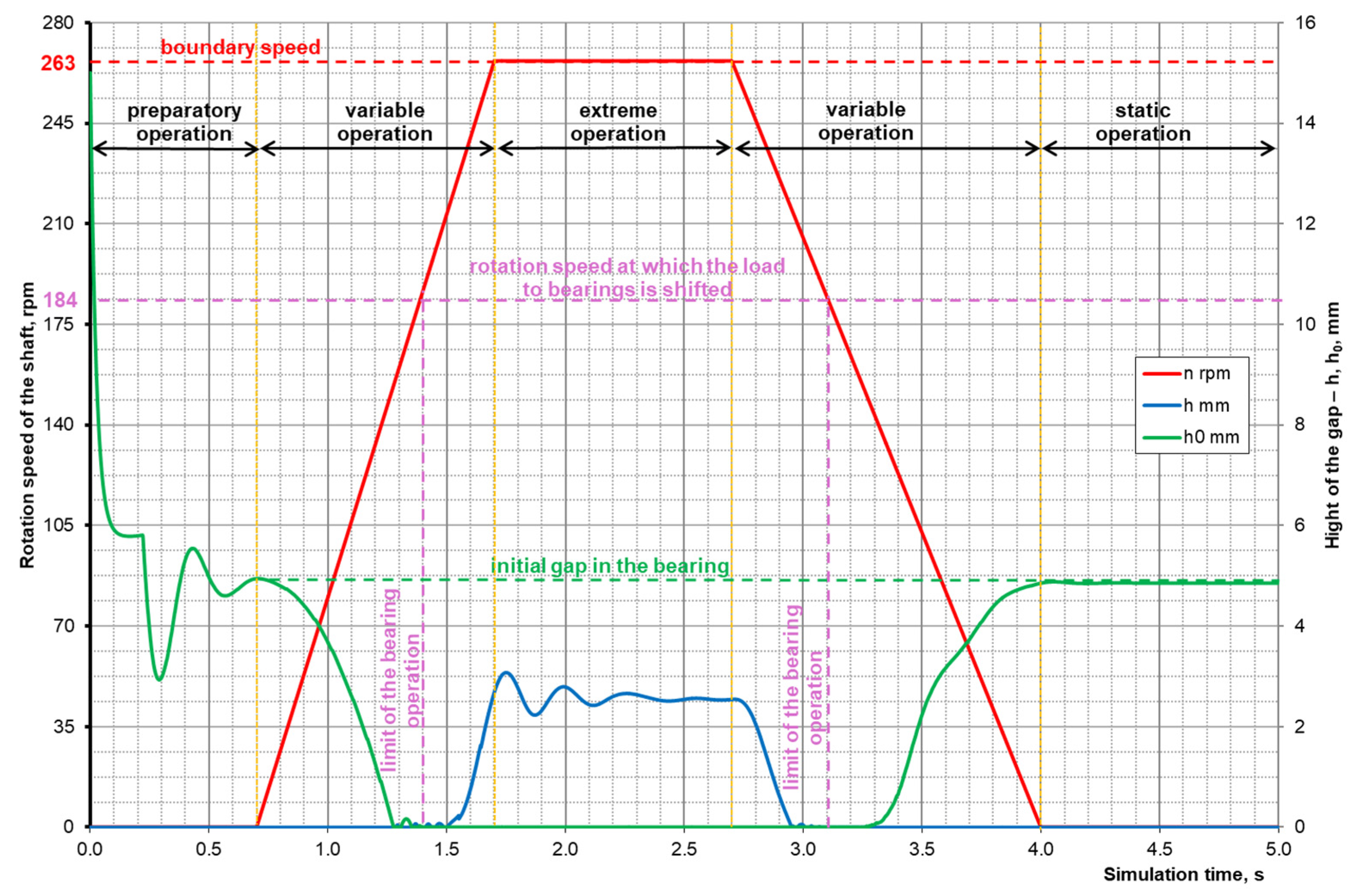
Figure 21 shows a graph obtained as a result of simulating the operation of the mechanism for automatically switching the load to the bearings for the given parameters in Table 4. The graph in Figure 21 shows the curves of three parameters over time: the curve of changes in the rotation speed of the wind turbine shaft (n) is the red line; the curve of changes in the height of the lubrication gap (h0) is the green line; and the curve of changes in the height of the gap (h) showing the distance of the sliding sleeve from the raceway of the thrust roller bearing is the blue line. Based on the assumption of the simulation of the mechanism’s operation, the rotation speed of the wind turbine (n) was determined.
During the time (t) from 0 s to 0.7 s, the rotation speed of the wind turbine shaft was set at 0 rpm and the height of the lubrication gap (h0) was assumed to be 15 mm. In this part of the graph, we observe the preparatory work during which the height of the lubrication gap (h0) changes from the initial value of 15 mm to a value of approximately 5 mm.
During the time (t) from 0.7 s to 1.7 s, the rotational speed of the wind turbine shaft is variable and increases from 0 rpm to the limit value. As the rotational speed of the motor shaft increases, the height of the lubrication gap (h0) begins to decrease. This is caused by the deflection of the lever with inertial masses and the displacement of the supporting sleeve. When the rotation speed of the wind turbine shaft reaches the load-switching speed, the height of the lubrication gap (h0) reaches 0 mm. At this operating point, the load-carrying capacity (Q) begins to be taken over by the plain bearing and the thrust bearing is relieved. Further increasing the rotation speed only increases the gap height (h).
In the time (t) from 1.7 s to 2.7 s, the rotation speed of the wind turbine shaft reaches the limit value. At this rotational speed, the gap (h) reaches its maximum height.
During the time (t) from 2.7 s to 4.0 s, the rotation speed of the wind turbine shaft decreases from the maximum to 0 rpm. As the rotation speed decreases, the gap height (h) begins to decrease. When the gap height (h) reaches 0 mm, the lubrication gap height (h0) increases. Due to the increasing height of the lubrication gap (h0), the plain bearing loses its ability to carry the load (Q) and the load is taken over by the thrust rolling bearing. A further decrease in the rotation speed of the wind turbine shaft causes an increase in the height of the lubrication gap (h0) until the wind turbine stops, i.e., the bearing reaches a state of static operation.
During the time (t) from 4.0 s to 5.0 s, the rotation speed of the wind turbine shaft is equal to 0 rpm. During this time, the bearing operation is static. The entire load (Q) is carried by the thrust bearing. The height of the lubrication gap (h0) is approximately 5 mm.
Based on the simulation of the work cycle of the automatic bearing load switching mechanism, the correctness of using this type of design solution is confirmed. The analysis of the data obtained from the simulation shows that the developed kinematic structure of the automatic bearing load switching mechanism ensures efficient load transfer between two types of bearings used in the hybrid bearing solution for wind turbines with a vertical axis of rotation.

5.3. Evaluation of Technical Parameters of the Equivalent Segment Bearing

The assumed axial load to the bearing Q and the geometric parameters of the equivalent segment bearing are given in Table 5.
It was assumed that the plain bearing was filled with VG 10 oil according to the ISO VG classification. The oil at a temperature of 15 °C has the following parameters [48]:
Oil densityρ = 817 kg/m3;
Kinematic viscosity coefficientν = 28 mm2·s−1;
Dynamic viscosity coefficient η = 0.02288 Pa·s;
Specific heat of oilcp = 1920 J·(kg·K)−1.
The load capacity criterion of a plain bearing is the dimensionless load capacity index K, determined from the Formula (5) [47].
The graph of dependence of the shaft rotation speed n0 on the bearing load capacity index K and the height of the lubrication gap h0 is shown in Figure 22.
According to the documentation of the considered wind turbine, the nominal shaft rotation speed is nnom = 320 rpm. When considering the concept of a hybrid bearing for the wind turbine shaft, it was assumed that the plain bearing takes over the total vertical load to the shaft at a boundary rotation speed of
n 0 = 180   r p m
Then, the average peripheral speed of the shaft journal is:
υ = 1.374 m s
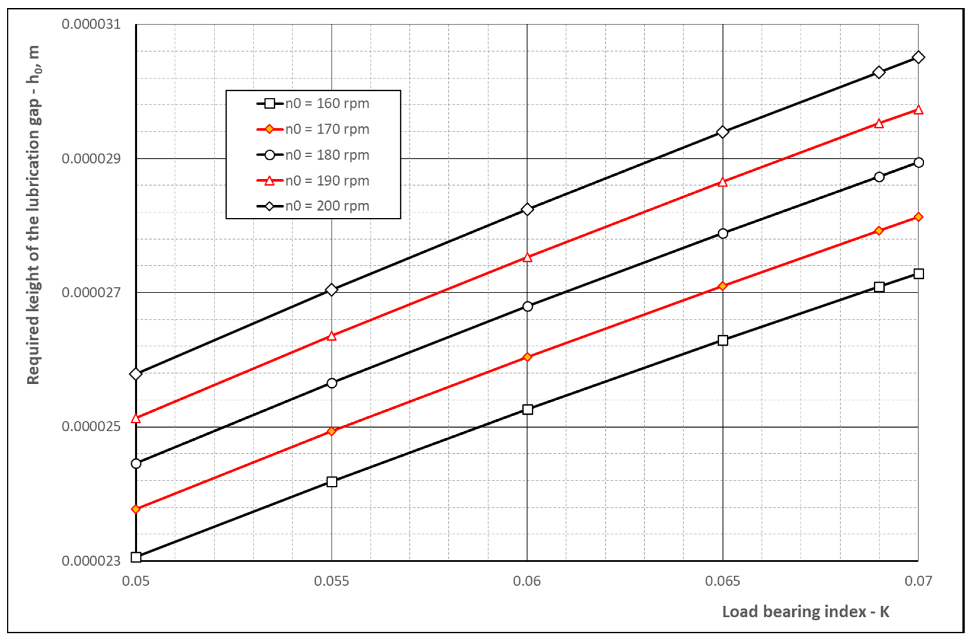
Figure 23 shows a graph of the relationship between the height of the lubrication gap h0 and the load-bearing capacity index K for rotational speeds n0 in the range of 160–200 rpm.
In the case of rotation speed n0 = 180 rpm shaft load bearing index K reaches K = 0.065 for the following height of the lubrication gap:
h 0 = 2.8 · 10 5   m
According to the calculations, the analysed segment bearing meets both the conditions of permissible surface pressure and the requirement to avoid heating the bearing.
As already noted at the beginning, the estimated calculations of the plain bearing model parameters are initial. A more detailed analysis of the properties of the plain bearing shown in Figure 18 will be possible based on observations and laboratory test results of the prototype of the hybrid wind turbine shaft-bearing system. They will be implemented during further research work.

6. Conclusions

At the current stage of development of the European Green Deal—a package of ecological transformation initiatives adopted by the EU—it is very important to look for technical solutions that will enable the gradual replacement of fossil energy sources with renewable energy sources. Wind turbines with a vertical axis of rotation are becoming more and more popular among both researchers and scientists, as well as users, especially individual users. A problem that significantly affects the expansion of prosumer applications is ensuring long durability, high efficiency, and the required quietness of the bearing system of the main shaft of a wind turbine. The analysis of currently used shaft-bearing systems in wind turbines enabled the authors of this publication to develop proposals for unique hybrid bearing concepts, which, thanks to the combination of the beneficial properties of two known methods for shaft bearing, are characterized by the following:
  • Low resistance to movement and high efficiency of the hydrodynamic thrust bearing, at a speed enabling the creation of a hydrodynamic lubrication effect.
  • Low resistance to movement and quiet operation of the thrust bearing when starting the wind turbine and its free run until it stops.
Two concepts of the hybrid bearing have been developed, differing in the shape of the plain bearing journal surface, namely:
  • A hybrid bearing with a conical journal shape, which has a compact structure but greater sensitivity to the transverse load to the shaft when using a wind turbine with a vertical axis of rotation.
  • A hybrid bearing with a spherical journal and relatively large overall dimensions, which can transfer, with a significantly reduced surface pressure, large longitudinal forces and the transverse load acting on the main shaft of the wind turbine.
The presented hybrid bearings are durable, highly efficient, and quiet in operation, constituting an important contribution to climate protection activities. They are equipped with a mechanism for automatic load switching between roller and plain bearings. The start-up and run-down behaviour of the hybrid bearing means that the plain bearing always operates exclusively under hydrodynamic lubrication. A layer of lubricating liquid between the journal and the plain bearing bush is always present, both when operating at nominal speed, as well as at standstill or during start-up, because then the full load on the shaft is taken over by the rolling bearing. This results in a favourable situation in which there is never any metal-to-metal contact between the journal and the bush. This is one of the main advantages of the developed designs, not found in other solutions.
Selection of the rotation speed of the wind turbine shaft at which the bearing load will be switched is possible by changing the mass of the inertial weights. This allows the user of the wind turbine to constantly adjust the operation of the hybrid bearing to the prevailing conditions at the place of the wind turbine operation, when, for example, dense buildings around the turbine cause a significant change in wind conditions. This is another advantage not found in other wind turbine bearing designs. Thanks to this design, the hybrid bearing has long operational durability. This is because the rolling bearing supporting the start-up and run-down of the wind turbine works only for a relatively short time, as confirmed by the simulation (Figure 20), and is at rest during the remaining time. However, a plain bearing operating only with liquid lubrication does not wear out at all.
In simulation tests of the kinematics mechanism automatically switching load to bearings, used in a hybrid bearing with a spherical journal shape, a solid simulation model of this mechanism was created in the Autodesk Inventor—Dynamic Simulation software environment. There are four operating states: preparatory work, static work, work at variable shaft speeds, and work at extreme shaft speeds. The subject of the analysis was the relationship between the rotation speed of the shaft and the height of the lubrication gap h0 in the plain bearing and the gap—h—between the raceway of the thrust rolling bearing and the sliding bushing. It has been shown that the thrust rolling bearing will be unloaded at a speed higher than n0 = 184 rpm. The developed mechanism for automatic bearing load switching ensures efficient load transfer between two types of bearings used in the hybrid shaft-bearing system of a vertical-axis wind turbine.
From the estimated calculations of the technical parameters of a plain bearing with a spherical journal, it has been confirmed that with the considered axial load to the bearing of 2020 N, the bearing load capacity index K will reach a critical value for the lubrication gap height h0 = 28 µm and shaft rotation speed n0 = 180 rpm.
Due to a number of simplifying assumptions, discussed in detail in the work, the technical parameters of the discussed hybrid bearings are approximate. A detailed analysis of the functional properties, especially of the plain bearing with a spherical journal, and verification of the results of the calculations will be possible only on the basis of observations and laboratory test results of the prototype, the construction and testing of which is planned in the next stage of the research work. The analyses carried out so far indicate that the technical feasibility of producing a hybrid bearing prototype does not pose any difficulties. The materials and standardized components of a hybrid bearing are typical and generally available.

Author Contributions

Conceptualization, S.S. and S.M.; Methodology, G.G. and M.S.; Software, G.G.; Validation, D.A. and J.M.; Formal analysis, S.S.; Investigation, M.S. and W.G.; Resources, D.A.; Data curation, J.M.; Writing—original draft, W.G. and S.M.; Writing—review & editing, D.A.; Visualization, G.G. and W.G.; Supervision, S.S.; Funding acquisition, W.G. All authors have read and agreed to the published version of the manuscript.

Funding

This research received no external funding.

Data Availability Statement

The original contributions presented in the study are included in the article, further inquiries can be directed to the corresponding author.

Conflicts of Interest

Grzegorz Głuszek, Wojciech Grzegorzek, Daniel Adamecki have no conflicts of interest to declare. Stanisław Szweda, Marek Szyguła, Jarosław Mikuła and Stanislaw Mikuła are co-inventors of the patent: “Bearing node of a wind turbine with a vertical axis of rotation” applied for on 2022-03-07-application no: P.440590. The patent was awarded on 2024-08-05. Patent information is provided in the manuscript’s reference [27]. Opis zgłoszeniowy wynalazku P.440590 (uprp.gov.pl). The patented invention, described in Section 3.1, is one of two technical solutions of hybrid bearing discussed in the manuscript. In addition, the above-mentioned authors certify that they have no other conflicts of interest to declare.

Nomenclature

Notations and Symbols
CFD Computational Fluid Dynamics;
EHD Electrohydrodynamic;
HAWT Horizontal-Axis Wind Turbine;
VAWT Vertical-Axis Wind Turbine;
b, lsegment width (see Figure 19), mm;
dj inner diameter of the bearing pan (see Figure 18), mm;
e1arm of action of the inertial mass lever (see Figure 16), m;
e2operating arm of the mechanism switching lever (see Figure 16), m;
F1 force in the pressing spring (see Figure 14), N;
F1,0 force in the pressing spring after relieving the rolling bearing (see Figure 15), N;
F2 reaction of the intermediate element (see Figure 14), N;
F3 centrifugal force, N;
FCcentrifugal force of the inertial mass, N;
G0 total weight of the lever (3) and the inertial weight (8) (see Figure 14), N;
g gravity acceleration, m·s−2;
hheight of the gap above the thrust rolling bearing (see Figure 16), m;
h0height of the lubricating gap, m;
Kthe dimensionless load capacity index, -;
Kmaxmaximum value of the criterion for the bearing load capacity, -;
k0permissible pressure of an equivalent segment bearing, MPa;
L1–L5 geometric features (see Figure 14), mm;
L1,0–L4,0 geometric features (see Figure 15), mm;
m mass of turbine, shaft and rotating bearing components, kg;
m0 total mass of the lever (3) and the inertial weight (8) (see Figure 14), kg;
nrotational speed of the hybrid bearing, rpm;
n0 boundary rotational speed, rpm;
Pffriction torque generated in the bearing, W;
p ¯   average pressure in an equivalent plain bearing, MPa;
Q shaft axial load, N;
Rradius of action of the inertial mass, m;
R0 distance of the centre of mass of the lever from the axis of rotation (see Figure 15), mm;
rmaverage radius of an equivalent segment bearing, mm;
rwinternal radius of an equivalent segment bearing, mm;
rzexternal radius of an equivalent segment bearing, mm;
αinitial angle of inertial mass lever deflection (see Figure 16), rad;
ηdynamic viscosity coefficient, Pa·s;
μfriction coefficient, -;
υaverage peripheral speed of the shaft journal, m·s−1;
ω0boundary angular speed of the turbine shaft, s−1.

References

  1. Liu, J.; Lin, H.; Zhang, J. Review on the technical perspectives and commercial viability of vertical axis wind turbines. Ocean. Eng. 2019, 182, 608–626. [Google Scholar] [CrossRef]
  2. Winarno, B.; Gaguk Pratama Yudha, R.; Susanto, F. Performance Analysis VAWT Turbine Convex Savonius. Int. Res. J. Adv. Eng. Sci. 2019, 4, 62–65. [Google Scholar]
  3. Kyaw, H.Y.Y.; Theik, E.C.C.; Nyunt, K.Z. Design and Fabrication of H-Darrieous VAWT. Int. J. Trend Sci. Res. Dev. (IJTSRD) 2019, 3, 1570–1574. [Google Scholar]
  4. Fedak, W.; Gancarski, W.; Anweiler, S.; Niesłony, A.; Ulbrich, R. Turbina Wiatrowa VAWT—Pomiar sił Naporu Łopaty w Tunelu Aerodynamicznym. Napędy i Sterowanie 2018, Nr 5 May 2018; pp. 97–101. Available online: https://nis.com.pl/userfiles/editor/nauka/052018_n/Fedak.pdf (accessed on 12 July 2024).
  5. Zwierzchowski, J.; Laski, P.A.; Blasiak, S.; Takosoglu, J.E.; Pietrala, D.S.; Bracha, G.F.; and Nowakowski, L. Model tests of wind turbine with a vertical axis of rotation type Lenz 2. EPJ Web Conf. 2017, 143, 02150. [Google Scholar] [CrossRef]
  6. Didane, D.H.; Behery, M.R.; Al-Ghriybah, M.; Manshoor, B. 2024. Recent Progress in Design and Performance Analysis of Vertical-Axis Wind Turbines & mdash; A Comprehensive Review. Processes 2024, 12, 1094. [Google Scholar] [CrossRef]
  7. Węgrzyn, A.; Spirydowicz, A.; Grebski, W. Dilemmas of the energy transformation in Poland 2021/2022. Min. Mach. 2022, 40, 32–42. [Google Scholar] [CrossRef]
  8. Pietrykowski, K.; Kasianantham, N.; Ravi, D.; Gęca, M.J.; Ramakrishnan, P.; Wendeker, M. Sustainable energy development technique of vertical axis wind turbine with variable swept area—An experimental investigation. Appl. Energy 2023, 329, 120262. [Google Scholar] [CrossRef]
  9. Ghigo, A.; Faraggiana, E.; Giorgi, G.; Mattiazzo, G.; Bracco, G. Floating Vertical Axis Wind Turbines for offshore applications among potentialities and challenges: A review. Renew. Sustain. Energy Rev. 2024, 193, 114302. [Google Scholar] [CrossRef]
  10. Milewicz, B.; Czachor, A.; Pikoń, K. Przegląd istniejących technologii w dziedzinie energetyki wiatrowej—Obecnie stosowane rozwiązania pozwalające na pozyskanie energii z wiatru. Arch. Waste Manag. Environ. Prot. 2017, 19, 1–10. [Google Scholar]
  11. Hau, E. Wind Turbines: Fundamentals, Technologies, Application, Economics, 2nd ed.; Springer: Berlin/Heidelberg, Germany, 2006. [Google Scholar] [CrossRef]
  12. Aissaoui, A.G.; Tahour, A. Wind Turbines—Design, Control and Applications; IntechOpen: Rijeka, Croatia, 2016. [Google Scholar] [CrossRef]
  13. Technical and Operational Documentation. ECOROTE Hipar Sp. z o.o. Available online: www.ecorote.com.pl (accessed on 3 September 2024).
  14. Technical and Operational Documentation. JFVC FUH MURAT. Available online: www.wiatraki.murat.pl (accessed on 3 September 2024).
  15. PN-EN 61400-11:2013-07; Wind Turbines-Part 11: Acoustic Noise Measurement Techniques. Polish Committee for Standardisation: Warsaw, Poland, 2013.
  16. IEC 61400-2; Wind turbines-Part 2: Design Requirements for Small Wind Turbines. International Electrotechnical Commission: Geneva, Switzerland, 2006.
  17. Strzelczyk, P.; Szczerba, Z. Turbiny Wiatrowe z Pionową Osią Obrotu. Pneumatyka. 2011. no. 1/78. Available online: http://pneumatyka.com/archiwum/2011/78_11_01.pdf (accessed on 12 July 2024).
  18. Baworski, A.; Garbala, K.; Czech, P.; Witaszek, K. Estimation of the ability to use a mass of air from a moving vehicle in wind turbine propulsion. Sci. J. Silesian Univ. Technology. Ser. Transp. 2015, 88, 5–17. [Google Scholar] [CrossRef]
  19. Sondej, M. Turbiny Wiatrowe O Pionowej Osią Obrotu. Czysta Energia 2010, 5, 50. [Google Scholar]
  20. Pinheiro, K.A.; Custódio Filho, S.d.S.; Vaz, J.R.P.; Mesquita, A.L.A. Effect of bearing dissipative torques on the dynamic behavior of H-Darrieus wind turbines. J. Braz. Soc. Mech. Sci. Eng. 2021, 43, 410. [Google Scholar] [CrossRef]
  21. Polak, A.; Baranski, M. Wind Turbines Comparison; Zeszyty Problemowe-Maszyny Elektryczne; Sieć Badawcza Łukasiewicz-Górnośląski Instytut Technologiczny: Greaves City, Poland, 2006; volume 74, pp. 147–151. [Google Scholar]
  22. Peng, H.; Zhang, H.; Shangguan, L.; Fan, Y. Review of Tribological Failure Analysis and Lubrication Technology Research of Wind Power Bearings. Polymers 2022, 14, 3041. [Google Scholar] [CrossRef] [PubMed]
  23. Hart, E.; de Mello, E.; Dwyer-Joyce, R. Wind turbine main-bearing lubrication—Part 1: An introductory review of elastohydrodynamic lubrication theory. Wind Energy Sci. 2022, 7, 1021–1042. [Google Scholar] [CrossRef]
  24. Chen, Z.; Tu, X.; Hu, Y.; Li, F. Real-Time Bearing RUL Estimation Based on the Frozen Convolutional and Activated Memory Neural Network. IEEE Acces 2019, 7, 96583–96593. [Google Scholar] [CrossRef]
  25. Mikula, J.; Grzegorzek, W.; Adamecki, D.; Głuszek, G.; Mikuła, S. Siłownia Wiatrowa Zwłaszcza dla Indywidualnych Odbiorców. Zgłoszenie Patentowe nr P.441411 z dnia 08.06.2022r. Opis Zgłoszeniowy Wynalazku P.441411 (uprp.gov.pl). Available online: https://api-ewyszukiwarka.pue.uprp.gov.pl/api/collection/4ff24539b23072d5fb4ee3a0f1b7b083 (accessed on 12 July 2024).
  26. Grzegorzek, W.; Adamecki, D.; Mikuła, J.; Borek, W.; Głuszek, G.; Mikuła, S. Shaft bearing of wind turbine with vertical axis of rotation. Q. Tribol. 2022, 299, 9–17. [Google Scholar] [CrossRef]
  27. Szelka, M.; Szweda, S.; Szyguła, M.; Mikuła, J.; Mikuła, S.; Węzeł Łożyskowania Siłowni Wiatrowej o Pionowej osi Obrotu. Zgłoszenie Patentowe nr P.440590 z dnia 07.03.2022. Opis Zgłoszeniowy Wynalazku P.440590 (uprp.gov.pl). Available online: https://api-ewyszukiwarka.pue.uprp.gov.pl/api/collection/39176a50d77c1843e262506c0e1788f7 (accessed on 12 July 2024).
  28. Shen, Z.; Gong, S.; Zuo, Z.; Chen, Y.; Guo, W. Darrieus vertical-axis wind turbine performance enhancement approach and optimized design: A review. Ocean. Eng. 2024, 311, 118965. [Google Scholar] [CrossRef]
  29. Wasilczuk, M.; Gawarkiewicz, R.; Libera, M.; Wasilczuk, F.; Kinal, G. Bearing systems of wind turbines—Maintenance problem. Q. Tribol. 2015, 262, 187–198. [Google Scholar]
  30. Arias Velásquez, R.M. 2024. Bearings faults and limits in wind turbine generators. Results Eng. 2024, 21, 101891. [Google Scholar] [CrossRef]
  31. Sun, X. Performance Prediction and Enhancement of the New Floating Vertical Axis Wind Turbine (VAWT). Ph.D. Thesis, Institute of Applied Physics and Materials Engineering, University of Macau, Macau, China, 2021. [Google Scholar]
  32. Goryca, Z. Generators with permanent magnets used in small wind power plants. In Proceedings of the 2015 Selected Problems of Electrical Engineering and Electronics (WZEE), Kielce, Poland, 17–19 September 2015. [Google Scholar]
  33. Bujari, S.S.; Bentur, M.; Shirabadagi, S.; Kiran, M. Design and Fabrication of Savonius Wind Turbine. Int. J. Eng. Res. Technol. (IJERT) 2022, 10. [Google Scholar] [CrossRef]
  34. Zhu, J.; Zhang, Z.; Cao, D.; Du, S.; Guo, X.; Liu, P.; Yang, M. Research on combination of passive magnetic bearing and mechanical bearing for vertical axis wind turbine. Int. J. Appl. Electromagn. Mech. 2021, 66, 475–489. [Google Scholar]
  35. Chalageri, G.R.; Bekinal, S.I.; Doddamani, M. Dynamic Analysis of 650 W Vertical-Axis Wind Turbine Rotor System Supported by Radial Permanent Magnet Bearings. Eng. Proc. 2023, 59, 56. [Google Scholar] [CrossRef]
  36. Al-Talib, A.A.M.; Redzuan, M.R.M.; Abd Hamid, A.R. A Levitating Frictionless Vertical Windmill. In Proceedings of the 2022 International Conference on Artificial Life and Robotics (ICAROB2022), Oita, Japan, 20–23 January 2022; pp. 892–899. Available online: https://alife-robotics.co.jp/members2022/icarob/data/html/data/OS/OS20/OS20-6.pdf (accessed on 2 September 2024).
  37. Ghulam, A.; Uzma, A. Design, construction and study of small scale vertical axis wind turbine based on a magnetically levitated axial flux permanent magnet generator. Renew. Energy 2017, 101, 286–292. [Google Scholar] [CrossRef]
  38. Hosnan, N.; Nor, K.A.M.; Ahmad, N.I.; Mokhtaruddin, H.; Rahman, D.H.A.; Saad, S.S.; Zakariya, M.Z.; Nazlan, A.; Azizan, N. Development of Vertical Axis Wind Turbine (VAWT) using Magnetic Levitation (MAGLEV). J. Adv. Res. Eng. Knowl. 2020, 10, 23–35. [Google Scholar]
  39. Krenicky, T.; Mascenik, J.; Coranic, T.; Ruzbarsky, J. Operating characteristics of bearings with magnetic nanoparticles doped lubricant. Mining Mach. 2023, 41, 168–174. [Google Scholar]
  40. Degtyar, V.G.; Grakhov, Y.V.; Krivospitskiy, V.P.; Filipowicz, M.W.; Petrovich, P.Y. Wind Power Plant. Academician V.P. Makeyev State Rocket Centre JSC. Patent RU123850U1, 10 January 2013. [Google Scholar]
  41. Qu, J.; Liu, R.; Chen, Y.; Qu, P.; Zhao, Y. Friction Clutch Formula Vertical Axis Wind Power Generation Set. Patent CN206111429U, 19 April 2017. [Google Scholar]
  42. Zhai, Y.; Zhang, Y.; Wan, L.; Zhou, Y.; Zeng, D.; Liu, S.; Zhou, X.; Liu, J. Starting Device for Vertical Axis Wind Turbine (VAWT). Patent CN102705181A, 3 October 2012. [Google Scholar]
  43. Chen, X.; Chen, Z. Wind Power Generation Driving Mechanism. Patent CN103216398A, 24 July 2013. [Google Scholar]
  44. Brownstein, I.; Daviri, J. Vertical-Axis Wind Turbine with Multi-Point Bearing Support. Patent WO2019023005, 31 January 2019. [Google Scholar]
  45. Liu, S.; Zhang, W.; Niu, G.; Chou, S. Railway Type Large Vertical Axis Wind Turbine. Patent CN201763530U, 16 March 2011. [Google Scholar]
  46. Fella, G. Wind Turbine System and Bearing Assembly. Dive Turbinen GMBH & Co. Kg. Patent WO2024056906, 21 March 2024. [Google Scholar]
  47. Spałek, J. Łożyska ślizgowe. In Podstawy Konstrukcji Maszyn; Skoć, A., Spałek, J., Markusik, S., Eds.; WNT: Warszawa, Poland, 2008; Volume 2. [Google Scholar]
  48. Spałek, J. Zarys tribologii i inżynierii smarowania. In Podstawy Konstrukcji Maszyn; Skoć, A., Spałek, J., Markusik, S., Eds.; WNT: Warszawa, Poland, 2008; Volume 2. [Google Scholar]
Figure 1. Configuration of bowl-shaped floating straight-blade VAWT (according to [31]): 1—foundation box, 2—water, 3—floating bowl-shaped shell, 4—shaft, 5—blades, 6—electricity generator.
Energies 17 05189 g001
Figure 2. Diagram of a levitating VAWT wind turbine installed on frictionless magnetic bearings (configuration of magnets, blades, rotors, stators and a shaft) (according to [36]): 1—shaft, 2—magnetic bearing, 3—rotor magnets, 4—stator coils, 5—blades, 6—support struts.
Energies 17 05189 g002
Figure 3. Bearing of a wind turbine using the magnetic bearing relief based on permanent magnets (according to [40]): 1—body, 2—magnetic bearing, 3—blades.
Energies 17 05189 g003
Figure 4. Scheme diagram of the wind turbine with a friction clutch (according to [41]): 1—turbine tower, 2—friction clutch, 3—blades.
Energies 17 05189 g004
Figure 5. Diagram of a wind turbine with a generator starting mechanism (according to [42]): 1—clamping components, 2—friction disc, 3—inertial sliders, 4—arm, 5—blades.
Energies 17 05189 g005
Figure 6. Diagram of a wind turbine with a drive transmission mechanism using the rollers (according to [43]): 1—clutch seat, 2—roller, 3—large tooth gear, 4—small tooth gear, 5—blades.
Energies 17 05189 g006
Figure 7. Bearing of a wind turbine using the plain bearings (according to [46]): 1—body, 2—sliding surface, 3—base, 4—lubricating oil.
Energies 17 05189 g007
Figure 8. Hybrid bearing with a conical-shaped journal where: 1—upper plain bearing enclosure, 1a—turbine main shaft, 1b—expansion rings, 2—base, 3—lever, 4—intermediate element, 5—rolling bearing raceway, 6—plain bearing, 7—rolling bearing, 8—inertial weight, 9—spring, 10—adjusting screw.
Energies 17 05189 g008
Figure 9. Three-dimensional model of the hybrid bearing with a conical journal.
Energies 17 05189 g009
Figure 10. Lever of the wind turbine bearing load switching mechanism: 1a—main shaft of the turbine, 3—lever, 4—intermediate element, 5—rolling bearing raceway, 8—inertial weight, 9—spring, 10—adjusting screw, 12—pressuring spring.
Energies 17 05189 g010
Figure 11. Hybrid bearing with a spherical-shaped journal: 1—tubular shaft, 2—expansion ring, 3—spherical journal of the plain bearing, 4—support sleeve, 5—plain bearing shell, 6—lubricating liquid, 7—enclosure, 8—base of the plain bearing, 9—thrust roller bearing, 10—compression spring 11—sliding sleeve, 12—adjusting sleeve, 13—base, 14—inertial weight lever, 15—inertial weight, 16—inertial lever axis, 17—self-lubricating bearing, 18—console, 19—building ceiling, 20—damping pad, Q—longitudinal load on the shaft, R—radius of rotation, n—rotational speed of the wind turbine shaft.
Energies 17 05189 g011
Figure 12. Three-dimensional model of a hybrid bearing with a spherical journal (a)—view, (b)—cross-section: 1—tubular shaft, 2—expansion ring, 3—spherical journal of the plain bearing, 4—support bushing, 5—pan, 6—lubricating liquid, 7—enclosure, 8—plain bearing base, 9—trust roller bearing, 17—self-lubricating bearing, 18—console, 19—building ceiling, 20—damping pad, 21—vertical ribs.
Energies 17 05189 g012
Figure 13. Design form of the automatic bearing load switching mechanism: 1—tubular shaft, 2—expansion ring, 4—supporting bushing, 9—trust roller bearing, 10—pressure spring, 11—moving bushing, 12—adjusting bushing, 13—base, 14—inertial weight lever, 15—inertial weight, 16—pressure spring.
Energies 17 05189 g013
Figure 14. Load diagram of the lever of the bearing load switching mechanism in the case of a standstill wind turbine: G0—weight of the lever and inertial weight, F1—force in the pressure spring, F2—reaction of the intermediate element.
Energies 17 05189 g014
Figure 15. The system of forces acting on the lever after relieving the rolling bearing.
Energies 17 05189 g015
Figure 16. Kinematic diagram of the mechanism for automatically switching the load to the bearings, where: 1—fixed raceway of the thrust roller bearing, 2—sliding sleeve, 3—compressing spring, 4—supporting sleeve, 5—ball journal of the plain bearing, 6—bushing, 7—inertial mass, 8—lever of the switching mechanism, 9—axis of rotation of the lever of the load switching mechanism, 10—tubular shaft, Q—axial load, FC—centrifugal force of the inertial mass, R—radius of action of the inertial mass, e1—arm of action of the inertial mass lever, e2—operating arm of the mechanism switching lever, α—initial angle of inertial mass lever deflection, n—rotational speed of the hybrid bearing, h0—height of the lubrication gap of the plain bearing, h—height of the gap above the thrust rolling bearing.
Energies 17 05189 g016
Figure 17. A solid model used to simulate the operation of the automatic mechanism for switching the load to bearings, where: 1—fixed raceway of a thrust roller bearing, 2—sliding sleeve, 3—compressing spring, 4—tubular shaft, 5—supporting sleeve, 6—ball journal of a plain bearing, 7—bushing, 8—switching mechanism lever, 9—inertial mass, A—swivel connection, B—swivel and slide connection, C—3D contact connection.
Energies 17 05189 g017
Figure 18. Assumed design of a plain bearing with a spherical journal.
Energies 17 05189 g018
Figure 19. Schematic diagram of an equivalent segment bearing.
Energies 17 05189 g019
Figure 20. Rotation of the lever to create a lubrication gap of 1 mm between the lever and the intermediate element.
Energies 17 05189 g020
Figure 21. Simulation of operation of the mechanism for automatically shifting the load to bearings.
Energies 17 05189 g021
Figure 22. Dependence of the shaft rotation speed n0 on the load-bearing capacity index K and on the height of the lubrication gap h0.
Energies 17 05189 g022
Figure 23. Dependence of the required height of the lubrication gap h0 on the load bearing index K for the selected values of shaft rotation speed n0.
Energies 17 05189 g023
Table 1. Technical parameters of vertical-axis wind turbines (VAWTs) [13,14].
ParameterValue
Turbine modelECOROTE 0.3 KWECOROTE 1 KWECOROTE 1.5 KWECOROTE 2.8 KWJFVC 3 KWJFVC 5 KWJFVC 10 KW
Rotor diameter, m112.22.23.23.24
Height of the blades, m1.22.171.531.81.83.6
Starting wind speed, m·s−1221.51.252.52.53
Rated wind speed, m·s−110101012121212
Limit wind speed, m·s−125252525404040
rpmmax536550250250505050
Total weight, kg4852155185235288400
Rated power, W3001000150028003000500010,000
Max power, W6001252200036703500600011,000
Turbine typeVertical
Drive transmissionGenerator on a joint turbine axle
BladesAluminiumComposite
Noise level acc. to PN-EN 61400-11 Standard [15]Does not exceed 46 dB at a distance of 60 m at wind speed 8 m·s−1
Anticorrosion protectionYes
Conformity with the standardsCE, IEC 61400-2 [16], 61400-11
Table 2. Determination of force F1 in the pressing spring in the case when the turbine shaft is standstill.
ParameterSymbolValue
Mass of the shaftm200 kg
Mass of the leverm01.92 kg
Lever geometric features (see Figure 14)L168 mm
L221 mm
L3119 mm
L432 mm
L54 mm
Force in the pressing springF1201.7 N
Table 3. Determination of boundary rotation speed n0 at which total load is taken over by the plain bearings.
ParameterSymbolValue
Force in the pressing springF1,0278 N
Mass of the leverm01.92 kg
Lever geometric features (see Figure 15)L1,068 mm
L3,021 mm
L4,0119 mm
R032 mm
Boundary angular speedω030.76 s−1
Boundary rotation speedn0293.7 rpm
Table 4. Parameters of the automatic mechanism for switching the load to bearings.
ParameterValue
Simulation time (t)5 s
Load to the shaft (Q)2020 N
Gravity acceleration (g)9.81 m·s−2
Preparatory lubrication gap height (h0)15 mm
Inertial mass (9)1.543 kg
Mass moment of inertia of inertial masses (α = 0°)29,377 kg·mm2
Compressing spring stiffness (3)400 N·mm−1
Compressing spring damping effect (3)10 N·s·mm−1
3D contact connection stiffness (C)1000 kN·mm−1
3D contact joint damping (C)10 N·s·mm−1
Table 5. Technical parameters of the equivalent segment bearing.
ParameterSymbolValue
Axial loadQ2020 N
Internal radiusrw50 mm
External radiusrz95.81 mm
Average radiusrm72.90 mm
Segment widthb, l45.81
Average pressure in an equivalent plain bearing p ¯ 0.120 MPa
Disclaimer/Publisher’s Note: The statements, opinions and data contained in all publications are solely those of the individual author(s) and contributor(s) and not of MDPI and/or the editor(s). MDPI and/or the editor(s) disclaim responsibility for any injury to people or property resulting from any ideas, methods, instructions or products referred to in the content.