Article

Research on the Influence of Moisture in the Solid Insulation Impregnated with an Innovative Bio-Oil on AC Conductivity Used in the Power Transformers

1
Department of Economics, Vincent Pol University in Lublin, 2, Choiny Street, 20-816 Lublin, Poland
2
Department of Electrical Devices and High Voltage Technology, Lublin University of Technology, 38a, Nadbystrzycka Street, 20-618 Lublin, Poland
3
Department of High Voltage and Power Engineering, West Pomeranian University of Technology, 37, Sikorskiego Street, 70-313 Szczecin, Poland
4
Nynas AB Raffinaderivagen, 21, Nynashamn Stoc, 149 82 Nynashamn, Sweden
5
Energo-Complex, Sp. z o.o., 9, Lotników Street, 41-949 Piekary Śląskie, Poland
*
Author to whom correspondence should be addressed.
Energies 2024, 17(20), 5164; https://doi.org/10.3390/en17205164
Submission received: 9 September 2024 / Revised: 14 October 2024 / Accepted: 16 October 2024 / Published: 17 October 2024

Abstract

:
The study determines the frequency–temperature dependence of the conductivity of a moist solid insulation component of power transformers, impregnated with the innovative bio-oil NYTRO® BIO 300X, manufactured from plant-based raw materials. The research was conducted for six moisture levels ranging from 0.6% to 5% by weight, within a frequency range from 10−4 Hz to 5 · 103 Hz and measurement temperatures from 20 °C to 70 °C, with a 10 °C step. The conduction model for both DC and AC, based on the quantum mechanical phenomenon of electron tunneling between water nanodroplets, was used to analyze the obtained results. It was determined that the frequency dependence of the conductivity of pressboard-bio-oil-moisture composites is influenced by two factors as follows: the activation energy of conductivity and the activation energy of relaxation time. For each moisture content, 16 values of the activation energy of the relaxation time and 16 values of the activation energy of conductivity were determined. It was found that the values of activation energy of conductivity and relaxation time are equal and independent of moisture content, frequency, and temperature. Based on 192 residual activation energy values, the mean generalized activation energy value for the relaxation time and conductivity was calculated with high precision, resulting in ΔE ≈ (1.02627 ± 0.01606) eV. The uncertainty of its determination was only ±1.6%. This indicates that electron tunneling from the first nanodroplet to the second, causing AC conductivity, and their return from the second nanodroplet to the first, determining the relaxation time, occur between the same energy states belonging to the water nanodroplets located in the pressboard impregnated with bio-oil. For each moisture content, the curves obtained for different measurement temperatures were recalculated to a reference temperature of 20 °C using the generalized activation energy. It was found that the shifted curves obtained for different temperatures perfectly overlap. Increased moisture content shifts the recalculated curves toward higher conductivity values. It was established that for all moisture contents in the lowest frequency range, conductivity is constant (DC conductivity). A further increase in frequency causes a rapid rise in conductivity. The increasing period can be divided into two stages. The first stage occurs up to about 100 Hz–101 Hz, depending on the moisture content. In the second stage, the rate of conductivity increase is higher, and its value depends on moisture content. The lower the moisture content, the faster the conductivity increases. Recalculation using the generalized activation energy eliminated the effect of temperature on the curves. It was found that the shapes of the recalculated curves and their position relative to the coordinates depend only on the moisture content in the composite. The equality of the activation energy of the relaxation time and conductivity established in the study, as well as their independence from frequency and moisture content in the pressboard impregnated with NYTRO® BIO 300X bio-oil, allows for recalculating the curves of electrical parameters determined at any operating temperatures of the transformer to a reference temperature, for example, 20 °C. Comparing the curve obtained for the transformer, recalculated to the reference temperature, with reference curves determined by us in the laboratory for different moisture contents, will allow for the precise determination of the moisture content of the solid insulation component impregnated with NYTRO® BIO 300X bio-oil. This will contribute to the early detection of approaching critical moisture content, threatening catastrophic transformer failure.

1. Introduction

The reliability of power transformers largely depends on the quality of insulation. For many years, insulation has predominantly been made of cellulose materials. The moisture content of cellulose after transformer manufacturing can reach 8% by weight or higher [1,2,3]. Such a high moisture content prevents the transformer from being brought into service. To reduce moisture content, vacuum drying is used for hermetically sealed transformers at a pressure below 1 hPa at elevated temperatures. This reduces moisture content to about 0.8% by weight [4,5]. After drying, the transformer is vacuum-filled with insulating oil with a moisture content of 3–7 ppm and heated to a temperature above 60 °C [6,7]. In the cellulose immersed in oil, the impregnation process occurs, involving the filling of capillaries with oil, which improves the insulating properties of cellulose.
During the decades of transformer operation, moisture slowly penetrates into the transformer and dissolves in the oil. The oil then delivers water molecules to the cellulose. Cellulose materials absorb water because the solubility of water in it is about 1000 times greater than in oil [8]. This causes a gradual increase in the moisture content of the liquid–solid insulation [5,9,10]. The critical moisture content of paper–oil insulation is considered to be 5% by weight [5,11,12,13]. Exceeding this value may lead to a catastrophic transformer failure.
Several electrical methods are used to determine the moisture content of transformer insulation. The RVM method [14,15,16] determines the relationship between relaxation time and water content. The PDC method [17,18,19] measures the dependence of DC conductivity on insulation moisture content. The FDS method [20,21,22] uses AC parameters. Currently, the FDS method is the most commonly used for analyzing insulation conditions. Modern FDS meters, in addition to measuring electrical parameters, also estimate the moisture content of cellulose insulation impregnated with mineral oil using the dedicated software.
In study [23], the DC conductivity of moist pressboard impregnated with mineral insulating oil was investigated. It was found that electrical conductivity is determined by the presence of moisture. The results of the study showed that the material exhibits a much faster than linear increase in conductivity with increasing moisture content. The publication [24] established that the observation of an exponential dependence of conductivity on the concentration of inclusions is sufficient to confirm that the material exhibits tunneling conductivity. The exponential dependence of conductivity on moisture content observed in [23] clearly indicates that DC conductivity occurs via electron tunneling between water molecules. Study [25] found that moisture in electrical pressboard impregnated with mineral oil spontaneously concentrates into nanodroplets containing an average of about 220 water molecules. AC studies confirmed that water is present as nanodroplets in the pressboard-mineral oil-moisture composite [25].
In recent years, the production of bio-oils from plant-based raw materials has begun to replace mineral insulating oil, produced from non-renewable petroleum-based raw materials. An example of such bio-oils is NYTRO® BIO 300X, produced by Nynas AB Raffinaderivagen, Nynashamn, Sweden [26]. The mechanical and thermal parameters of NYTRO® BIO 300X oil are superior to those of mineral and esters oils [27]. The breakdown voltage is comparable to that of mineral oils [26]. Permittivity is lower than that of mineral oils [28]. Furthermore, NYTRO® BIO 300X oil is biodegradable, which is important in the event of transformer decommissioning or failure. The use of bio-oils in power transformers reduces the carbon footprint during their production.
Estimating moisture content using the FDS method is based on the dependence of AC parameters on water content and temperature, previously determined in laboratory studies. These dependencies are referred to as reference or standard curves. According to the authors of the software estimating the moisture content of the solid insulation component [29], it accounts for moisture content ranging from 1% to 4% by weight. As can be seen, it does not include the most critical 5% by weight moisture content. As mentioned earlier, reaching or exceeding this value may pose the risk of transformer failure. The measurement temperatures were 20 °C, 50 °C, and 80 °C. Given the exponential dependence of conductivity on temperature, this small number of temperatures leads to low accuracy in determining activation energy. This reduces the accuracy of recalculating conductivity and other electrical parameters from the transformer insulation temperature to the reference temperature of 20 °C, thereby reducing the accuracy of estimating the moisture content of the cellulose component of insulation.
The use of innovative bio-oil in transformers, due to its mechanical, thermal, and electrical properties differing from those of mineral oil, requires the determination of reference curves for electrical parameters of the moist oil-impregnated pressboard. This will serve as a tool for the precise diagnostics of the liquid–solid insulation condition and for estimating the water content in the solid insulation component of transformers.
The objective of this study was to determine the frequency–temperature dependencies of conductivity and, based on this, to determine the activation energy of the relaxation time and the conductivity for moist solid insulation components of power transformers, impregnated with the innovative NYTRO® BIO 300X, for an extended range of moisture content from 0.6% to 5% by weight, and transformer operating temperatures from 20 °C to 70 °C.

2. DC and AC Conductivity of Pressboard-Insulating Oil-Water Composites–Theoretical Foundations

2.1. Classical Models of Polarization and Associated Conductivity

For a composite consisting of a dielectric matrix and conductive inclusions to exhibit DC conductivity, a percolation channel connecting the electrodes to which the measurement voltage is applied must be formed. In the case of composites where the grains of the conductive phase have macroscopic dimensions, the percolation channel is formed through the contact of neighboring grains [30]. Conductivity is different in nanocomposites, where the characteristic feature is that the dimensions of the conductive nano-grained phase are smaller than 100 nm [31,32]. In nanocomposites, direct contact between the grains of the conductive phase is not necessary for the formation of a percolation channel. This is related to the fact that the nanoparticles of the low-resistivity phase, in our case, water nanodroplets, placed in the insulating material, form potential wells. When the distances between potential wells are in the order of nanometers, the well-known quantum mechanical phenomenon of electron tunneling from one potential well to another occurs, causing current flow in the percolation channel. Conductivity through electron tunneling between potential wells is referred to as hopping conductivity [33].
The conduction of alternating current in nanocomposites occurs differently. In this case, clusters of dimensions much smaller than the distance between electrodes are sufficient for conductivity. Here too, direct contact between nanodroplets is not required. At high frequencies, these can even be pairs of nanodroplets located nanometers apart, between which electron tunneling occurs. This means that AC conductivity does not require the formation of percolation channels. Charge movement limited to nanometer-sized areas is sufficient. This phenomenon can be explained by analyzing the frequency dependence of conductivity for the simplest orientation polarization model, the Debye model. This model is described in detail in, for example, [34,35].
The Debye model describes an ideal dielectric that has permanent dipole moments in the form of molecules and contains no free current carriers (ions, electrons, and holes). Under the influence of an alternating electric field, the dipole moments change their orientation. This is sufficient for the flow of AC current in the dielectric, which can be characterized by the corresponding AC conductivity. According to the Debye model, dielectric loss, also referred to as the imaginary component of permittivity, is described by the equation:
ε = ( ε s ε ) ω τ m 1 + ( ω τ m ) 2 ,
where ε″ is the dielectric loss, εs is the low-frequency permittivity, ε is the high-frequency permittivity, τm = const is the relaxation time, ω = 2πf is the angular frequency, and f is the frequency.
The position of the maximum in the dependence of the dielectric loss on angular frequency occurs at ωm = 1/τm. The dielectric loss is a function of AC conductivity [36] as follows:
ε = σ ( f ) ε 0 ω ,
where σ(f) is the AC conductivity and ε0 is the vacuum permittivity.
From Equations (1) and (2), it follows that:
σ ( f ) = ε ε 0 ω = ( ε s ε ) ε 0 ( ω τ m ) 2 τ m [ 1 + ( ω τ m ) 2 ]
Using Equation (3) the frequency dependencies of AC conductivity for the Debye model were calculated (Figure 1). The calculations were performed for the following parameters: ε s ε = 20 , ε 0 = 8.85 10 12 F m and for six relaxation times from τ1m = 100 s to τ6m = 10−5 s.
From Figure 1, it can be seen that at frequencies ω ≪ 1/τm conductivity is a quadratic function of frequency. As the relaxation time τm decreases, the curves shift to the region of higher frequencies. A characteristic feature of the Debye model is that as the frequency approaches zero (DC current), conductivity also approaches zero. Substituting ω = 2πf = 0 into Equation (3), we obtain:
σ ( ω = 0 ) = 0 ,
This means that as the frequency approaches zero (DC voltage), resistivity approaches infinity. A similar situation is characteristic of the Cole–Cole model [37], which assumes the existence of a distribution of relaxation times around the expected value τm. The most important conclusions drawn from the Debye and Cole-Cole models are that in materials with orientation polarization, AC current flow is observed, and DC current is absent. It should be emphasized that the Debye and Cole–Cole models assume that charge movement occurs only in the space limited to the dimensions of a permanent dipole, usually a molecule. This eliminates the possibility of DC current flow between the electrodes. The dimensions of molecules are fractions of a nanometer. Under the influence of an alternating electric field, depending on its amplitude, the dipoles rotate from their initial state by no more than a few degrees. This means that the charge shift is in the order of thousandths of nanometers. This results in relatively low AC conductivity in dielectrics with orientation polarization.

2.2. DC and AC Conductivity Considering the Quantum Mechanical Phenomenon of Electron Tunneling

In pressboard-insulating oil-water nanodroplet composites below the percolation threshold, AC current will also flow. This occurs through electron tunneling in small clusters or even in pairs of potential wells, where the distances between wells are sufficient for electron tunneling. The distances over which electrons tunnel are several orders of magnitude larger than the movement of dipole moments and typically range from 5 to 10 or more nanometers [24]. This means that the conductivity of nanocomposites via tunneling is several orders of magnitude greater than in dielectrics with orientation polarization. The probability P of electron tunneling per unit time per unit volume between three-dimensional potential wells—nearest neighbors—is described by the equation [33]:
P = P 0 exp ( 2 R B r ) exp ( Δ E k T ) ,
where P0 = const is a numerical coefficient, r is the distance over which the electron tunnels, RB is the radius of the localization of the electron wave function in the potential well, known as the Bohr radius, ΔE is the activation energy of tunneling, k is the Boltzmann constant, and T is the temperature.
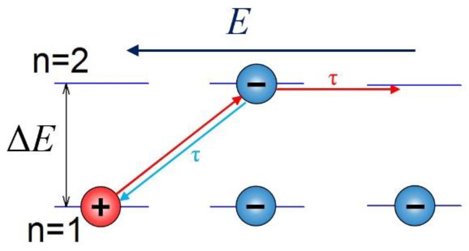
Tunneling described by Equation (5) is referred to as thermally activated tunneling. Activation energy is required for the valence electron to transition from the lowest occupied state in the first well to the lowest unoccupied state in the second well (Figure 2).
Tunneling causes the formation of an electric dipole and, consequently, an additional permittivity [25]. In study [38], a hopping conductivity model for DC and AC conditions was proposed. This model, for the first time, considers that after each tunneling event, the electron remains in the well into which it tunneled for a time called the dipole existence time or relaxation time. Only after the relaxation time can it undergo another tunneling event. The occurrence of relaxation time is related to the fact that the tunneling electron must absorb thermal energy, ΔE, from its surroundings in the form of phonons. Due to the specific values of phonon energies, this energy is almost never equal to the energy gap between states n = 1 and n = 2. This means that after tunneling, the electron must release the excess energy to its surroundings, also in the form of phonons. This process is called electron thermalization. For this purpose, the electron requires a certain amount of time, called the relaxation time in our case. After time τ, the electron can tunnel in two possible directions. First, with a probability p it can jump to the third well (Figure 2). This results in DC current flow. Second, with a probability of 1-p it can return from to the first.
AC conductivity value is [25]:
σ r = σ 0 ( 1 c o s ω τ + 2 p c o s ω τ ) ,
where σr is the conductivity, σ0 =const, p is the probability of jumping from the second well to the third well, and τ is the relaxation time.
From the analysis of Equation (6), it follows that for DC currents the conductivity:
σ r = 2 p σ 0
This means that, unlike the Debye and Cole–Cole models, when the frequency decreases to zero (DC current), the conductivity remains non-zero. High-frequency conductivity is described by the equation:
σ r = σ 0
Analysis of the probability of the transition p included in Equations (6) and (7), showed that its value is [25]:
p = p 0 e x p ( 2 R B r Δ E k T + U 1 2 k T ) ,
where U is the potential energy of the dipole:
U = e 4 π ε ε 0 r
Considering the values of tunneling probability, Equation (5), and further transition from the second well to the third well, Equation (9), the DC or AC conductivity in the analyzed model is described by the expression:
σ = σ 0 e x p ( 2 R B r Δ E k T + U 1 2 k T ) ,
where σ0 is a numerical coefficient.
The frequency dependence of AC conductivity in the frequency range between low (DC current), described by Equation (7), and high frequency, Equation (8), is described by [25], as follows:
σ ( f ) ~ f α ( f ) ,
where α(f) is the frequency coefficient.
The frequency coefficient in Equation (12) is a function of the probability p. It is less than 2 and decreases as the probability p increases.

3. Materials and Methods

The study used electrical pressboard, produced by Weidmann (Weidmann Holding AG, Rapperswil, Switzerland) [39], with a thickness of 0.5 mm. The innovative biodegradable NYTRO® BIO 300X oil [26], produced by Nynas (Nynas AB Raffinaderivagen, Nynashamn, Sweden) from plant-based raw materials, was used for impregnation. Moistening and impregnation were performed according to the standard procedure described in many publications, see, for example, [40,41,42,43,44,45]. The preparation of samples proceeded as follows. The cut samples were dried in a vacuum. The drying temperature was 80 °C. The drying time was 72 h. Then, the remaining water content in the samples was determined using the Karl-Fischer titration method [46], which was (0.6 ± 0.05)% by weight. The sample with the lowest moisture content of 0.6% by weight, after vacuum drying, was immediately immersed in bio-oil. The subsequent preparation of this sample was identical to that of samples with higher moisture content. The following procedure was used for their preparation. After drying, the sample’s mass was determined. Then, considering the remaining water content after drying, the sample’s mass after achieving the desired moisture content of X% by weight was calculated. The sample was exposed to air, where the dry pressboard absorbed moisture. This process took place under constant mass control of the sample. When the mass reached the desired value, the sample was immersed in a container with bio-oil. The container was hermetically sealed and placed in a thermostat at 45 °C. Each sample was impregnated in a separate container. The bio-oil volume in the container was less than ten times the sample’s volume. The temperature of 45 °C was used to accelerate the impregnation process because the kinematic viscosity of bio-oil at 45 °C is about three times lower than at room temperature [26]. As is known, the lower the kinematic viscosity, the faster the impregnation process [47]. The impregnation time was 14 days. In this way, six samples of the pressboardbio-oil-moisture composite with water content ranging from 0.6% to 5% by weight were prepared. Then, the sample was placed in a measuring three-electrode capacitor. The capacitor was placed in a glass vessel filled with bio-oil. The vessel was hermetically sealed and placed in a thermostat. Electrical measurements were performed at temperatures ranging from 20 °C to 70 °C, with a 10 °C step. The DIRANA FDS-PDC dielectric response analyzer, produced by OMICRON, with a frequency measurement range of 10−4 Hz–5000 Hz [48], was used for the measurements. According to the manufacturer [48], the measurement uncertainty at the ends of the measurement range is ±2%, and in the middle part, ±1%. First, DC measurements of polarization current were performed, followed by depolarization measurements. Each of these measurements took about 7 h. Subsequent tests involved AC measurements. The measurement setup was presented and thoroughly characterized in publications [49,50].

4. Study of DC and AC Conductivity of the Pressboard-Bio Insulating Oil-Moisture Composite

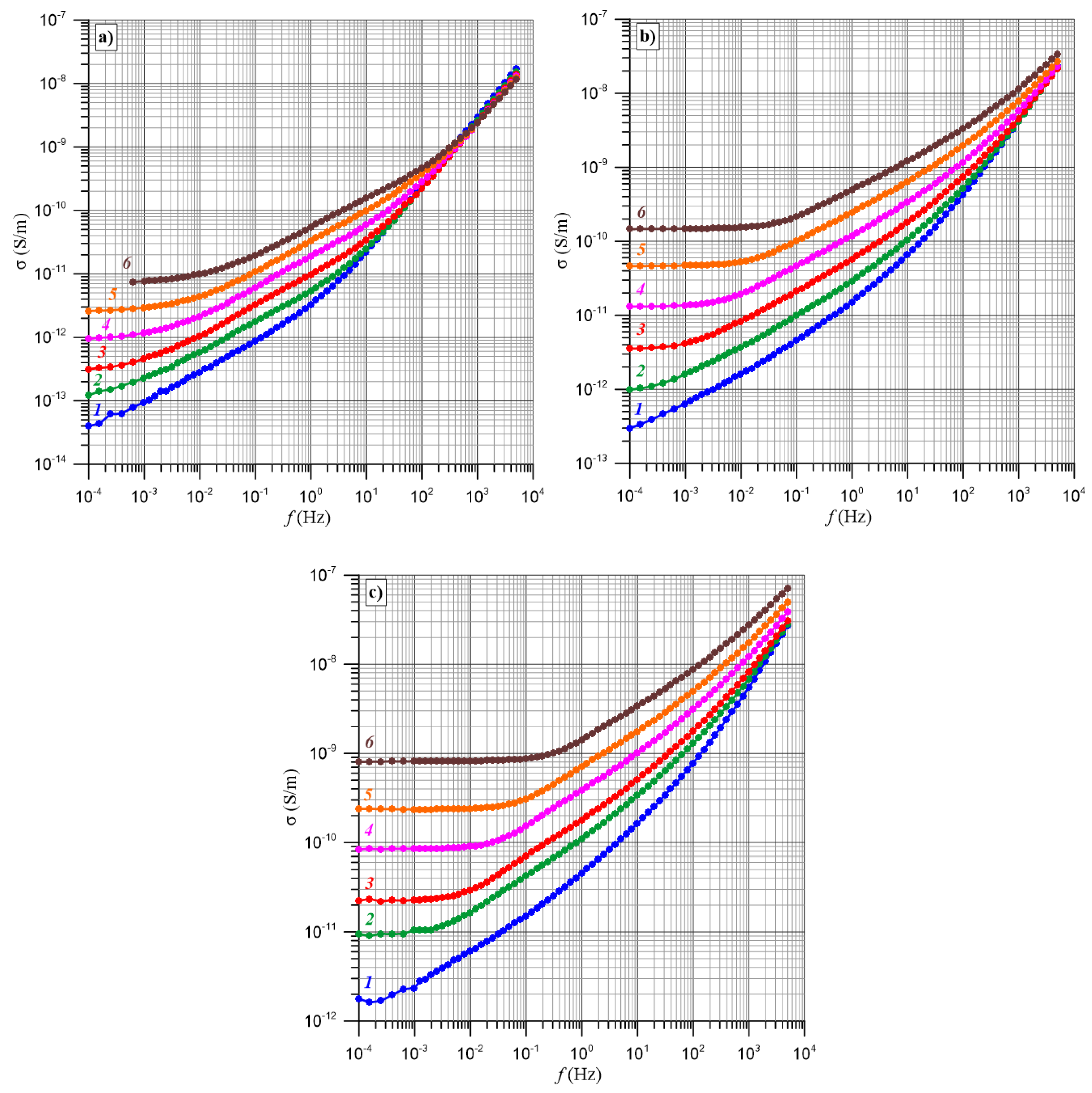
Figure 3 shows the frequency–temperature dependencies of AC conductivity for 1% by weight, 3% by weight, and 5% by weight moisture content. The figure shows that in the lowest frequency range, conductivity does not depend on frequency. Its value corresponds to the DC conductivity value. After exceeding a certain frequency value, an increase in conductivity is observed.
In articles [50,51], it was established that the frequency dependence of the conductivity of pressboard-oil-moisture composites is determined by two temperature factors. One of them is the temperature dependence of conductivity. The presence of activation energy of conductivity causes the conductivity curve to shift along the Y-axis with temperature changes. When the temperature changes, the relaxation time changes, and the σ(f) curve shifts along the X-axis. From Figure 3, it can be seen that in the low-frequency range, where σ(f) = const, temperature changes in the relaxation time do not affect the conductivity value. In this range, only the activation energy of conductivity influences conductivity. Utilizing this, the curves for temperatures of 30–70 °C were shifted along the X-axis to match the curve at 20 °C. An illustration of the results of such an operation is shown in Figure 4 for a sample with 3% by weight. This allowed for the elimination of the temperature dependence of conductivity on the curves, leaving only their dependence on the relaxation time.
To determine the activation energy of the relaxation time ΔE(τ), 16 conductivity values ranging from 10−12 S/m to 4 · 10−11 S/m, where the curves for all measurement temperatures are located, were selected from the curves in Figure 4. For each selected conductivity value, the frequency values for each measurement temperature were read. Based on them, Arrhenius plots were drawn, presented in Figure 5, and linear approximations were made.
From Figure 5, it can be seen that the plots are linear and are almost parallel to each other. The approximation results are very good, as the coefficients of determination R2 are very close to unity (Table 1). Based on the obtained approximation dependencies, the values of ΔE(τ) were calculated, as shown in Table 1. Based on the obtained 16 values of ΔEi(τ), the mean ΔE(τ) and its determination uncertainty were calculated as ΔE(τ) ≈ (1.064 ± 0.0246) eV. This indicates high calculation accuracy, as the uncertainty is only ±2.3%.
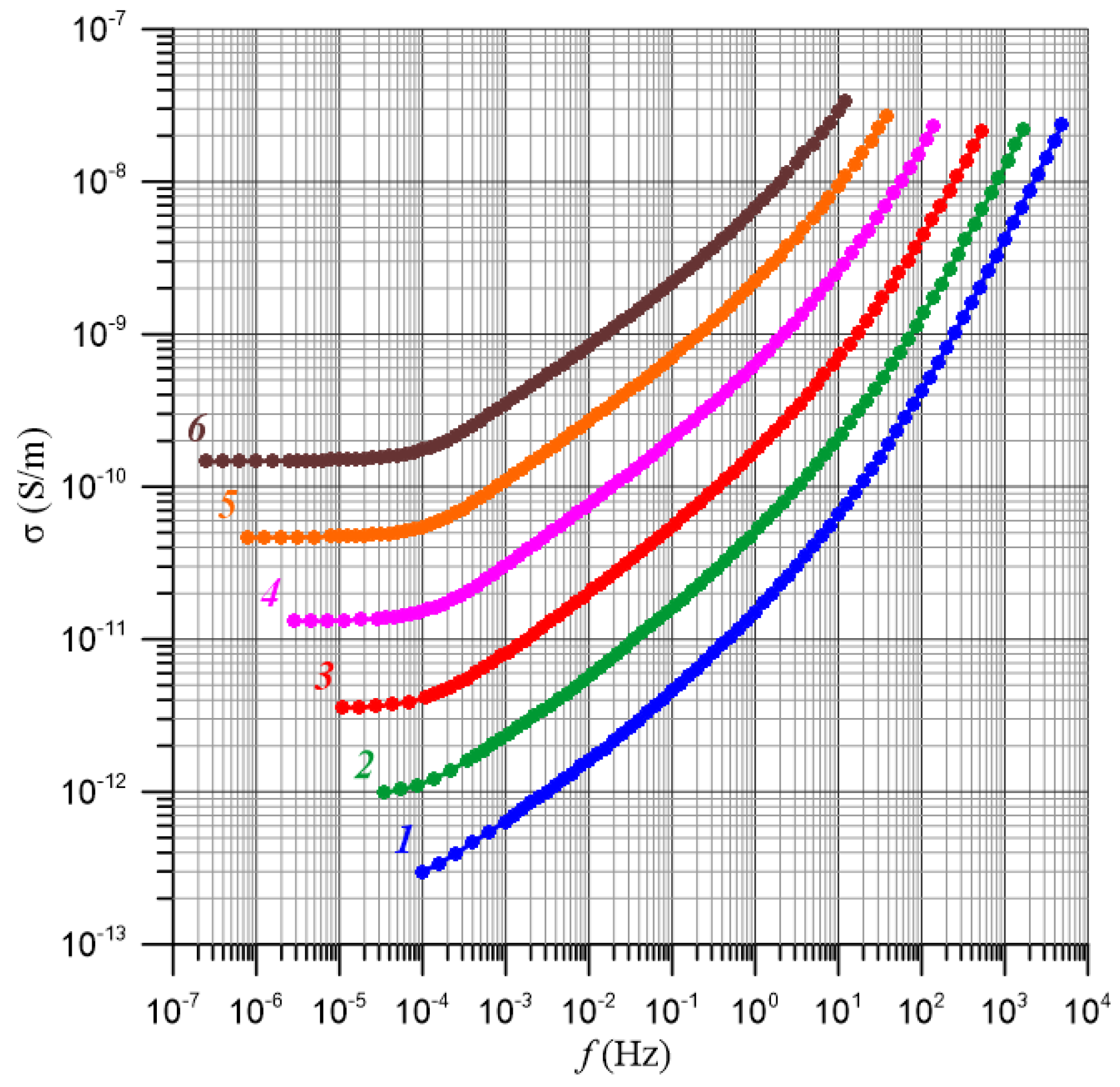
Using the calculated mean value of ΔE(τ), the curves from Figure 3 for a sample with 3% by weight moisture content were recalculated to a temperature of 20 °C, shifting them along the X-axis to the left. The recalculation results are presented in Figure 6.
The performed shift allowed for eliminating the influence of relaxation time on the curves, leaving only their dependence on the ΔE(σ). In Figure 6, 16 frequency values ranging from 10−4 Hz to 101 Hz, where the curves for all temperatures are located, were selected. Using the conductivity values for each selected frequency, Arrhenius plots were drawn, and linear approximations were made (Figure 7).
Based on this, 16 values of the ΔE(σ) were calculated, along with the mean value and its determination uncertainty. It was found that ΔE(σ) ≈ (1.086 ± 0.0151) eV. The uncertainty in this case is only ±1.4%. Comparing the values of ΔE(τ) ≈ (1.064 ± 0.0246) eV and conductivity ΔE(σ) ≈ (1.086 ± 0.0151) eV shows that they are equal within the uncertainty. The difference between the mean values is only 0.022 eV and is smaller than the uncertainty of determining the ΔE(τ), which is ±0.0246 eV. The equality of these activation energies over a wide frequency range means that electron tunneling from the first well to the second, causing AC conductivity, and their return from the second well to the first, determining the relaxation time, occur between the same energy states. These states belong to water nanodroplets located in the pressboard impregnated with bio-oil (Figure 2).
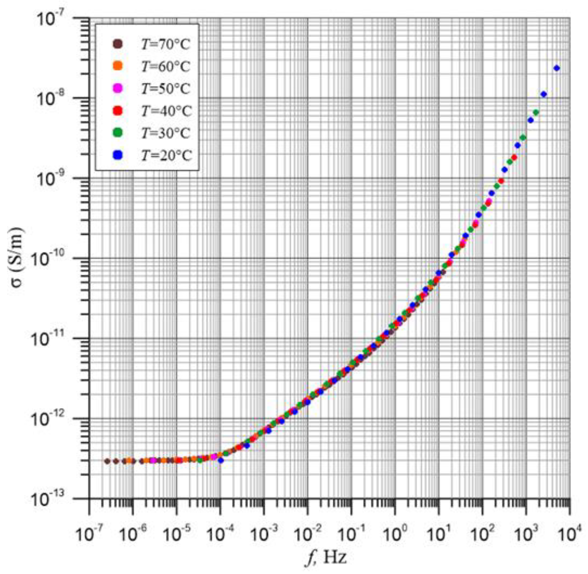
The obtained ΔE value was used to recalculate the curves shown in Figure 3 to a reference temperature of 20 °C. First, the curves were shifted along the X-axis using the activation energy (Figure 6), and then along the Y-axis. The recalculation results are presented in Figure 8.
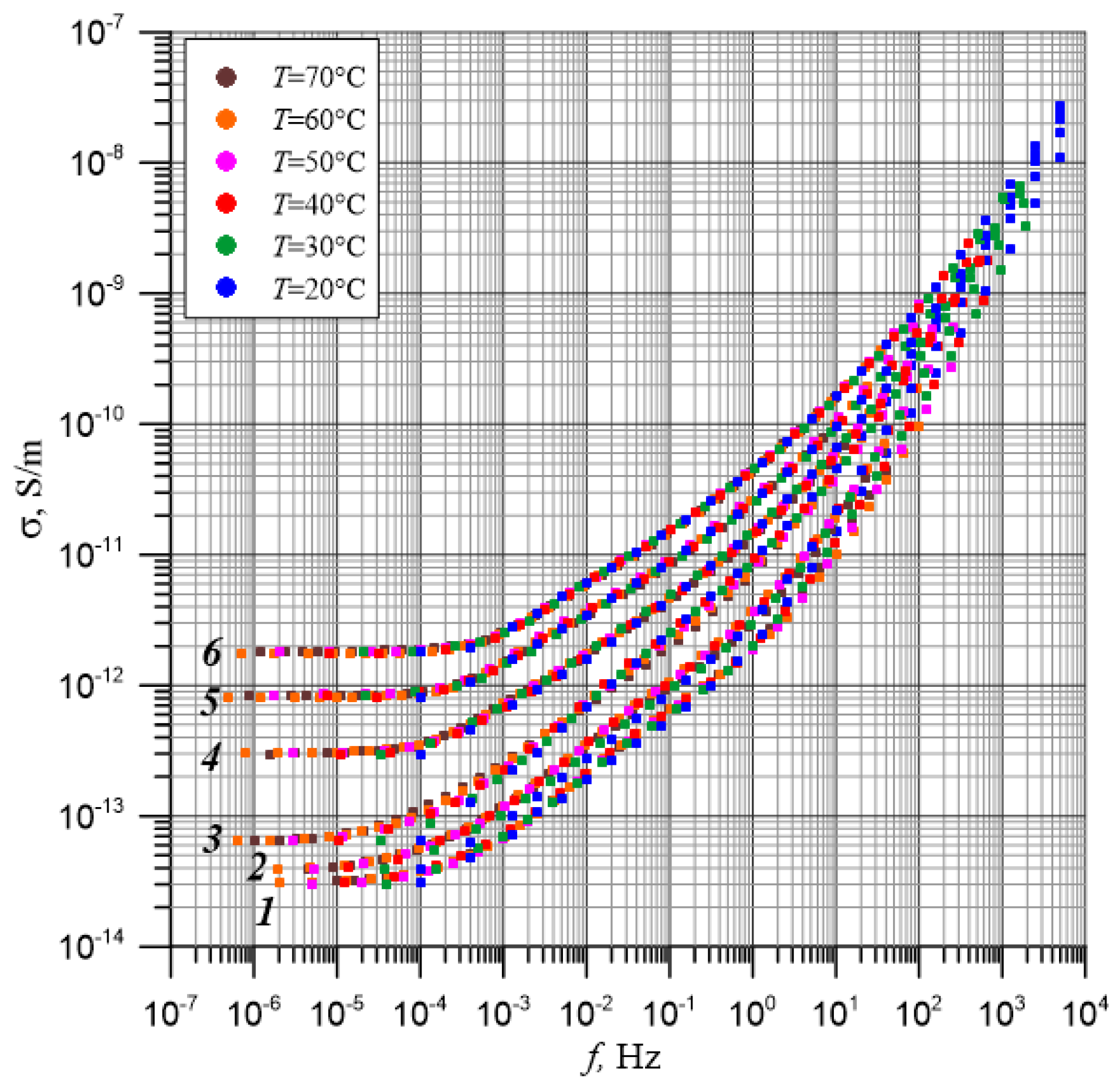
Figure 8 shows that after shifting using generalized activation energy, the curves obtained for different temperatures perfectly overlap. Similar calculations were performed for the remaining five moisture contents. For each of them, 16 values of the ΔE(τ) and 16 values of the ΔE(σ) were determined. In total, this gives 192 residual activation energy values. The generalized activation energy value for all moisture contents is ΔE ≈ (1.02627 ± 0.01606) eV. This value is approximately 19% higher than that of mineral oil [51]. Such a large difference should be taken into account in the FDS diagnosis of power transformer insulation. The uncertainty in its determination is very low, only ±1.6%. This means that the values of activation energy of ΔE are equal and independent of moisture content, frequency, and temperature. Using the generalized value of ΔE, the curves obtained for temperatures 30–70 °C were recalculated to a temperature of 20 °C for the remaining moisture contents. The recalculation results are presented in Figure 9.
Figure 9 shows that a slight scatter of measurement points occurs in the lowest frequency range, where, according to the manufacturer’s information, the highest measurement uncertainty is observed [48]. Recalculating the curves presented in Figure 9 allowed for eliminating the influence of temperature on them. The curves presented in Figure 9 depend only on frequency and moisture content. Increasing moisture content shifts the curves towards higher conductivity values. The figure shows that for all moisture contents in the lowest frequency range, conductivity is constant. A further increase in frequency causes a rapid rise in conductivity. The increasing section can be divided into two stages. The first stage extends up to about 100 Hz–101 Hz, depending on moisture content. At this stage, the curves for different moisture contents are almost parallel. In the second stage, the rate of conductivity increase significantly accelerates. Additionally, the rate of increase starts to depend on moisture content. The lower the moisture content, the faster the conductivity increases at this stage. This means that the shapes of the recalculated curves and their position relative to the coordinates depend only on the moisture content in the composite.
The operating temperature range of power transformers is relatively wide. The insulation temperature during diagnostics depends on the transformer’s load during and before the start of measurements, as well as on atmospheric conditions. Therefore, the insulation temperature of a transformer filled with NYTRO® BIO 300X during diagnostics may be within a wide range of operating temperatures and usually does not coincide with the measurement temperatures used in this study. The above discussion showed the equality of the ΔE(τ) and ΔE(σ) and their independence from frequency and moisture content in the pressboard impregnated with NYTRO® BIO 300X. This will allow the ΔE determined in this study to be used to recalculate the curves of electrical parameters determined at any operating temperatures of the transformer to a reference temperature, for example, 20 °C. Comparing the curve obtained for the transformer, recalculated to the reference temperature, with the standard curves of electrical parameters of insulation obtained in the laboratory for different moisture contents will allow for the precise determination of the moisture content of the solid insulation component impregnated with NYTRO® BIO 300X. This will contribute to the early detection of approaching critical moisture content, threatening catastrophic transformer failure.

5. Conclusions

The study examined the AC conductivity of the solid insulation component of transformers impregnated with innovative bio-oil NYTRO® BIO 300X. During years of transformer operation, moisture accumulates in the solid insulation component, significantly affecting the insulation quality. Therefore, the study was conducted on six samples with water content ranging from 0.6% by weight to the critical 5% by weight, which poses a risk of transformer failure. The hopping conductivity model under DC and AC conditions, based on the quantum mechanical phenomenon of electron tunneling, was used to analyze the obtained results.
For each moisture content, 16 values of the activation energy of the relaxation time and 16 values of the activation energy of conductivity were determined, resulting in a total of 192 residual activation energy values. It was found that the values of activation energy of conductivity and relaxation time are equal and independent of moisture content, frequency, and temperature. This means that electron tunneling from the first well to the second, causing AC conductivity, and their return from the second well to the first, determining the relaxation time, occur between the same energy states. These states belong to water nanodroplets located in the pressboard impregnated with bio-oil. Based on 192 residual values, the mean generalized activation energy value for the relaxation time and conductivity for all moisture contents, ranging from 0.6% by weight to 5% by weight, was calculated to be ΔE ≈ (1.02627 ± 0.01606) eV. This value is approximately 19% higher than that of mineral oil. Such a large difference should be taken into account in the FDS diagnosis of power transformer insulation. Using the generalized value of ΔE, the curves obtained for different measurement temperatures were recalculated to a temperature of 20 °C for each moisture content. This recalculation eliminated the influence of temperature on the curves. The shapes of the recalculated curves and their position relative to the coordinates depend only on the moisture content in the composite. Increasing moisture content shifts the recalculated curves towards higher conductivity values.
Comparing the curve obtained for the transformer, recalculated to the reference temperature, with the reference curves determined by us in the laboratory for different moisture contents, will allow for the precise determination of the moisture content of the solid insulation component impregnated with NYTRO® BIO 300X bio-oil. This will contribute to the early detection of approaching critical moisture content, threatening catastrophic transformer failure.

Author Contributions

Conceptualization, P.Z. and K.K.; methodology, P.Z., K.K., P.R., P.O., M.Z., R.P., M.S., P.M. and T.N.K.; software, K.K., P.R. and M.Z.; validation, P.Z., M.Z. and M.S.; formal analysis, P.Z., K.K., P.R., P.O., M.Z., R.P., M.S., P.M. and T.N.K.; investigation, K.K., P.R., P.O., M.Z. and P.M.; resources, K.K. and T.N.K.; data curation, K.K., P.R., P.O., M.Z., R.P., M.S. and T.N.K.; writing—original draft preparation, P.Z. and K.K.; writing—review and editing, T.N.K.; visualization, K.K. and T.N.K.; supervision, P.Z., K.K. and T.N.K.; project administration, K.K. and T.N.K.; funding acquisition, K.K., P.R., P.O. and T.N.K. All authors have read and agreed to the published version of the manuscript.

Funding

The research was supported from the state budget within the program of the Ministry of Education and Science entitled ‘Science for Society II’ project no. NdS-II/SP/0173/2024/01 total project value PLN 1,462,590.80.

Data Availability Statement

The original contributions presented in the study are included in the article, further inquiries can be directed to the corresponding author.

Conflicts of Interest

Author Rafal Pajak was employed by the company Nynas AB Raffinaderivagen. Authors Marek Szrot, Pawel Molenda were employed by the company Energo-Complex, Sp. z o.o. The remaining authors declare that the research was conducted in the absence of any commercial or financial relationships that could be construed as a potential conflict of interest.

References

  1. Graczkowski, A. Dielectric response of cellulose impregnated with different insulating liquids. Przegląd Elektrotech. 2010, 86, 223–225. [Google Scholar]
  2. Wei, Y.; Han, W.; Li, G.; Liang, X.; Gu, Z.; Hu, K. Aging Characteristics of Transformer Oil-Impregnated Insulation Paper Based on Trap Parameters. Polymers 2021, 13, 1364. [Google Scholar] [CrossRef] [PubMed]
  3. Qi, B.; Dai, Q.; Li, C.; Zeng, Z.; Fu, M.; Zhuo, R. The Mechanism and Diagnosis of Insulation Deterioration Caused by Moisture Ingress into Oil-Impregnated Paper Bushing. Energies 2018, 11, 1496. [Google Scholar] [CrossRef]
  4. Lundgaard, L.E.; Hansen, W.; Linhjell, D.; Painter, T.J. Aging of Oil-Impregnated Paper in Power Transformers. IEEE Trans. Power Deliv. 2004, 19, 230–239. [Google Scholar] [CrossRef]
  5. Oommen, T.V.; Prevost, T.A. Cellulose insulation in oil-filled power transformers: Part II—Maintaining insulation integrity and life. IEEE Electr. Insul. Mag. 2006, 22, 5–14. [Google Scholar] [CrossRef]
  6. Fabre, J.; Pichon, A. Deteriorating Processes and Products of Paper in Oil Application to Transformers. In Proceedings of the International Conference on Large High Voltage Electric Systems, Paris, France, 15–25 June 1960; p. 137. [Google Scholar]
  7. Liu, J.; Zhang, H.; Geng, C.; Fan, X.; Zhang, Y. Aging Assessment Model of Transformer Insulation Based on Furfural Indicator under Different Oil/Pressboard Ratios and Oil Change. IEEE Trans. Dielectr. Electr. Insul. 2021, 28, 1061–1069. [Google Scholar] [CrossRef]
  8. Prevost, T.A.; Oommen, T.V. Cellulose insulation in oil-filled power transformers: Part I—History and development. IEEE Electr. Insul. Mag. 2006, 22, 28–35. [Google Scholar] [CrossRef]
  9. Gielniak, J.; Graczkowski, A.; Moranda, H.; Przybylek, P.; Walczak, K.; Nadolny, Z.; Moscicka-Grzesiak, H.; Feser, K.; Gubanski, S. Moisture in cellulose insulation of power transformers—Statistics. IEEE Trans. Dielectr. Electr. Insul. 2013, 20, 982–987. [Google Scholar] [CrossRef]
  10. Raetzke, S.; Koch, M.; Krueger, M.; Talib, A. Condition assessment of instrument transformers using Dielectric Response Analysis. Elektrotech. Inftech. 2013. [Google Scholar] [CrossRef]
  11. Lelekakis, N.; Martin, D.; Guo, W.; Wijaya, J.; Lee, M. A field study of two online dry-out methods for power transformers. IEEE Electr. Insul. Mag. 2012, 28, 32–39. [Google Scholar] [CrossRef]
  12. Martin, D.; Perkasa, C.; Lelekakis, N. Measuring paper water content of transformers: A new approach using cellulose isotherms in nonequilibrium conditions. IEEE Trans. Power Deliv. 2013, 28, 1433–1439. [Google Scholar] [CrossRef]
  13. Subocz, J. Przewodnictwo i Relaksacja Dielektryczna Warstowywch Układów Izolacyjnych; Wydawnictwo Uczelniane, Ed.; Uczelniane Zachodniopomorskiego Uniwersytetu Technologicznego w Szczecinie: Szczecin, Poland, 2012; ISBN 8376631136/9788376631134. [Google Scholar]
  14. Martínez, M.; Pleite, J. Improvement of RVM test interpretation using a Debye equivalent circuit. Energies 2020, 13, 323. [Google Scholar] [CrossRef]
  15. Islam, M.M.; Lee, G.; Hettiwatte, S.N. A review of condition monitoring techniques and diagnostic tests for lifetime estimation of power transformers. Electr. Eng. 2018, 100, 581–605. [Google Scholar] [CrossRef]
  16. Fofana, I.; Hadjadj, Y. Electrical-Based Diagnostic Techniques for Assessing Insulation Condition in Aged Transformers. Energies 2016, 9, 679. [Google Scholar] [CrossRef]
  17. Sarkar, S.; Sharma, T.; Baral, A.; Chatterjee, B.; Dey, D.; Chakravorti, S. An expert system approach for transformer insulation diagnosis combining conventional diagnostic tests and PDC, RVM data. IEEE Trans. Dielectr. Electr. Insul. 2014, 21, 882–891. [Google Scholar] [CrossRef]
  18. Zheng, H.; Liu, J.; Zhang, Y.; Ma, Y.; Shen, Y.; Zhen, X.; Chen, Z. Effectiveness Analysis and Temperature Effect Mechanism on Chemical and Electrical-Based Transformer Insulation Diagnostic Parameters Obtained from PDC Data. Energies 2018, 11, 146. [Google Scholar] [CrossRef]
  19. Mishra, D.; Haque, N.; Baral, A.; Chakravorti, S. Assessment of interfacial charge accumulation in oil-paper interface in transformer insulation from polarization-depolarization current measurements. IEEE Trans. Dielectr. Electr. Insul. 2017, 24, 1665–1673. [Google Scholar] [CrossRef]
  20. Zhang, Y.; Liu, J.; Zheng, H.; Wang, K. Feasibility of a universal approach for temperature correction in frequency domain spectroscopy of transformer insulation. IEEE Trans. Dielectr. Electr. Insul. 2018, 25, 1766–1773. [Google Scholar] [CrossRef]
  21. Liu, J.; Fan, X.; Zhang, Y.; Zhang, C.; Wang, Z. Aging evaluation and moisture prediction of oil-immersed cellulose insulation in field transformer using frequency domain spectroscopy and aging kinetics model. Cellulose 2020, 27, 7175–7189. [Google Scholar] [CrossRef]
  22. Yang, L.; Chen, J.; Gao, J.; Zheng, H.; Li, Y. Accelerating frequency domain dielectric spectroscopy measurements on insulation of transformers through system identification. IET Sci. Meas. Technol. 2018, 12, 247–254. [Google Scholar] [CrossRef]
  23. Żukowski, P.; Kołtunowicz, T.N.; Kierczyński, K.; Subocz, J.; Szrot, M.; Gutten, M.; Sebok, M.; Jurcik, J. An analysis of AC conductivity in moist oil-impregnated insulation pressboard. IEEE Trans. Dielectr. Electr. Insul. 2015, 22, 2156–2164. [Google Scholar] [CrossRef]
  24. Shklovskii, B.I.; Efros, A.L. Electronic Properties of Doped Semiconductors; Springer Series in Solid-State Sciences; Springer: Berlin/Heidelberg, Germany, 1984; Volume 45, ISBN 978-3-662-02405-8. [Google Scholar]
  25. Żukowski, P.; Kierczyński, K.; Kołtunowicz, T.N.; Rogalski, P.; Subocz, J. Application of elements of quantum mechanics in analysing AC conductivity and determining the dimensions of water nanodrops in the composite of cellulose and mineral oil. Cellulose 2019, 26, 2969–2985. [Google Scholar] [CrossRef]
  26. NYTRO® BIO 300X—THE NEW BIO-BASED ALTERNATIVE from NYNAS, Transform. Technol. Mag. 2020, 46–51. Available online: https://www.powersystems.technology/community-hub/in-focus/nytro-bio-300x-the-new-bio-based-alternative-from-nynas.html (accessed on 2 September 2024).
  27. Wolmarans Carl, P.; Abrahams, R.; Pahlavanpour, B. Biodegradable electroinsulating fluids based on low viscosity hydrocarbons. Energetyka 2021, 9, 649–652. [Google Scholar]
  28. Wolmarans, C.; Gamil, A.; Al-Abadi, A.; Milone, M.; Jornaan, J.; Hellberg, R. Type Testing of 80 MVA Power Transformer with a new Bio-based, Biodegradable and Low Viscosity Insulating liquid. In Proceedings of the Conference: CIGRE Session, Paris, France, 28 August–2 September 2022; p. 11125. [Google Scholar]
  29. Koch, M.; Tenbohlen, S.; Krüger, M.; Kraetge, A. A Comparative Test and Consequent Improvements on Dielectric Response Methods. In Proceedings of the 15th International Symposium on High Voltage Engineering, Ljubljana, Slovenia, 27–31 August 2007. [Google Scholar]
  30. Mamunya, Y.P.; Davydenko, V.V.; Pissis, P.; Lebedev, E.V. Electrical and thermal conductivity of polymers filled with metal powders. Eur. Polym. J. 2002, 38, 1887–1897. [Google Scholar] [CrossRef]
  31. ISO/TS 80004-2:2015; Nanotechnologies—Vocabulary—Part 2: Nano-Objects. ISO: Geneva, Switzerland, 2015. Available online: https://www.iso.org/standard/54440.html (accessed on 3 December 2021).
  32. The European Commission. Commission Recommendation of 18 October 2011 on the definition of nanomaterial. Off. J. Eur. Union 2011, 38–40. Available online: https://eur-lex.europa.eu/LexUriServ/LexUriServ.do?uri=OJ:L:2011:275:0038:0040:EN:PDF (accessed on 1 September 2024).
  33. Mott, N.F.; Davis, E.A. Electronic Processes in Non-Crystalline Materials, 2nd ed.; Clarendon Press: Oxford, UK; New York, NY, USA, 1979; ISBN 9780198512882. [Google Scholar]
  34. Jonscher, A.K. Dielectric Relaxation in Solids; Chelsea Dielectrics Press: London, UK, 1983. [Google Scholar]
  35. Chelkowski, A. Fizyka Dielektryków; Wydaw. Naukowe PWN: Warszawa, Poland, 1993; ISBN 830111245X. [Google Scholar]
  36. Waygood, A. An Introduction to Electrical Science, 2nd ed.; Routledge: New York, NY, USA, 2019. [Google Scholar]
  37. Cole, K.S.; Cole, R.H. Dispersion and Absorption in Dielectrics I. Alternating Current Characteristics. J. Chem. Phys. 1941, 9, 341–351. [Google Scholar] [CrossRef]
  38. Żukowski, P.; Kołtunowicz, T.; Partyka, J.; Węgierek, P.; Komarov, F.F.; Mironov, A.M.; Butkievith, N.; Freik, D. Dielectric properties and model of hopping conductivity of GaAs irradiated by H+ ions. Vacuum 2007, 81, 1137–1140. [Google Scholar] [CrossRef]
  39. Available online: https://weidmann-electrical.com/insulation-technology/transformerboard/cellulose-based/ (accessed on 5 September 2024).
  40. Fofana, I.; Wasserberg, V.; Borsi, H.; Gockenbach, E. Retrofilling conditions of high-voltage transformers. IEEE Electr. Insul. Mag. 2001, 17, 17–30. [Google Scholar] [CrossRef]
  41. Ekanayake, C.; Gubanski, S.M.; Graczkowski, A.; Walczak, K. Frequency Response of Oil Impregnated Pressboard and Paper Samples for Estimating Moisture in Transformer Insulation. IEEE Trans. Power Deliv. 2006, 21, 1309–1317. [Google Scholar] [CrossRef]
  42. Walczak, K.; Graczkowski, A.; Gielniak, J.; Morańda, H.; Mościcka-Grzesiak, H.; Ekanayake, C.; Gubański, S. Dielectric frequency response of cellulose samples with various degree of moisture content and aging. Prz. Elektrotech. 2006, 1, 264–267. [Google Scholar]
  43. Zhang, J.; Zhang, B.; Fan, M.; Wang, L.; Ding, G.; Tian, Y.; Chen, Q. Effects of external radiation heat flux on combustion characteristics of pure and oil-impregnated transformer insulating paperboard. Process Saf. Prog. 2018, 37, 362–368. [Google Scholar] [CrossRef]
  44. Kouassi, K.; Fofana, I.; Cissé, L.; Hadjadj, Y.; Yapi, K.; Diby, K. Impact of Low Molecular Weight Acids on Oil Impregnated Paper Insulation Degradation. Energies 2018, 11, 1465. [Google Scholar] [CrossRef]
  45. Liu, J.; Fan, X.; Zhang, Y.; Lai, B.; Jiao, J. Analysis of low-frequency polarisation behaviour for oil-paper insulation using logarithmic-derivative spectroscopy. High Volt. 2021, 6, 460–469. [Google Scholar] [CrossRef]
  46. ASTM D1533-20; Standard Test Method for Water in Insulating Liquids by Coulometric Karl Fischer Titration. ASTM International: West Conshohocken, PA, USA, 2020. Available online: https://www.astm.org/d1533-20.html (accessed on 2 September 2024).
  47. Rowlinson, J.S.; Widom, B. Molecular Theory of Capillarity; Clarendon Press: Oxford, UK, 1982. [Google Scholar]
  48. DIRANA—The Fastest Way of Moisture Determination of Power- and Instrument Transformers and Condition Assessment of Rotating Machines. Omicron 2018, L2894. Available online: https://pdf.directindustry.com/pdf/omicron-electronics/dirana-fastest-way-moisture-determination-power-instrument-transformers-condition-assessment-rotating-machines/13971-42092.html (accessed on 3 September 2024).
  49. Żukowski, P.; Kołtunowicz, T.N.; Kierczyński, K.; Rogalski, P.; Subocz, J.; Szrot, M.; Gutten, M.; Sebok, M.; Korenciak, D. Dielectric losses in the composite cellulose–mineral oil–water nanoparticles: Theoretical assumptions. Cellulose 2016, 23, 1609–1616. [Google Scholar] [CrossRef]
  50. Zukowski, P.; Rogalski, P.; Koltunowicz, T.N.; Kierczynski, K.; Subocz, J.; Zenker, M. Cellulose Ester Insulation of Power Transformers: Researching the Influence of Moisture on the Phase Shift Angle and Admittance. Energies 2020, 13, 5511. [Google Scholar] [CrossRef]
  51. Zukowski, P.; Rogalski, P.; Koltunowicz, T.N.; Kierczynski, K.; Bondariev, V. Precise measurements of the temperature-frequency dependence of the conductivity of cellulose—Insulating oil—Water nanoparticles composite. Energies 2020, 14, 32. [Google Scholar] [CrossRef]
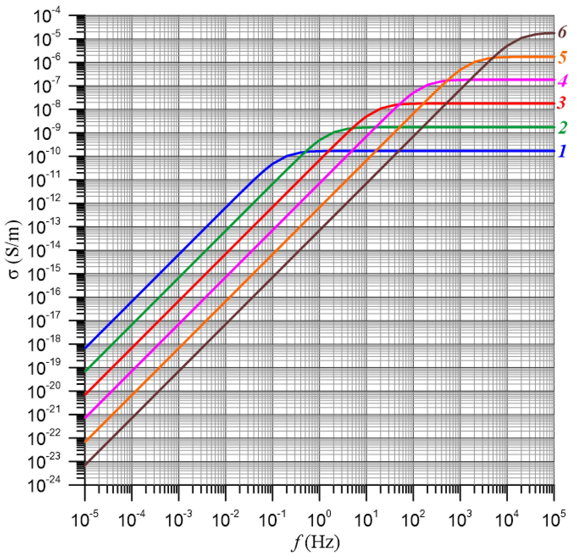
Figure 1. Frequency dependence of AC conductivity in the Debye model: 1—τ1m = 100 s, 2—τ2m = 10−1 s, 3—τ3m = 10−2 s, 4—τ4m = 10−3 s, 5—τ5m = 10−4 s, 6—τ6m = 10−5 s.
Energies 17 05164 g001
Figure 2. Ground state (n = 1) and first unoccupied state (n = 2), between which the electron tunnels; ΔE is activation energy.
Energies 17 05164 g002
Figure 3. Frequency dependencies of the pressboard-bio-oil-moisture composite conductivity for measurement temperatures of 20 °C—1, 30 °C—2, 40 °C—3, 50 °C—4, 60 °C—5 and 70 °C—6: (a) 1% by weight, (b) 3% by weight, (c) 5% by weight.
Energies 17 05164 g003
Figure 4. Values of σ(f) for temperatures of 20 °C—1, 30 °C—2, 40 °C—3, 50 °C—4, 60 °C—5, and 70 °C—6, shifted along the Y-axis to 20 °C for a sample with 3% by weight moisture content.
Energies 17 05164 g004
Figure 5. Arrhenius plots for determining the ΔE(τ) for a sample with 3% by weight moisture content.
Energies 17 05164 g005
Figure 6. Frequency dependencies of conductivity shifted along the X-axis for a sample with 3% by weight moisture content for temperatures of 20 °C—1, 30 °C—2, 40 °C—3, 50 °C—4, 60 °C—5, and 70 °C—6.
Energies 17 05164 g006
Figure 7. Arrhenius plots for determining the ΔE(σ) for a sample with 3% by weight moisture content. Numbering according to Table 1.
Energies 17 05164 g007
Figure 8. Curves of σ(f, T) shifted along the X and Y axes using generalized activation energy. For better clarity, every third measurement point has been plotted.
Energies 17 05164 g008
Figure 9. Curves of σ(f, T) shifted along the X and Y axes using generalized activation energy as follows: 1—moisture content 0,6% by weight, 2—1% by weight, 3—2% by weight, 4—3% by weight, 5—4% by weight, 6—5% by weight. For better clarity, every third measurement point has been plotted.
Energies 17 05164 g009
Table 1. Calculation results of the ΔE(τ) and ΔE(σ).
Noσ, S/mΔEi(τ) R i 2 ( τ ) f, HzΔEi(σ) R i 2 ( σ )
11.00 · 10−121.0150.99801.00 · 10−41.1100.9998
21.28 · 10−121.0210.99752.15 · 10−41.1010.9995
31.64 · 10−121.0260.99724.64 · 10−41.0970.9995
42.09 · 10−121.0400.99731.00 · 10−31.1000.9997
52.67 · 10−121.0520.99742.15 · 10−31.0990.9998
63.42 · 10−121.0610.99744.64 · 10−31.0980.9998
74.37 · 10−121.0700.99761.00 · 10−21.0960.9998
85.59 · 10−121.0770.99782.15 · 10−21.0910.9999
97.15 · 10−121.0800.99794.64 · 10−21.0830.9998
109.15 · 10−121.0820.99821.00 · 10−11.0770.9998
111.17 · 10−111.0840.99832.15 · 10−11.0730.9998
121.50 · 10−111.0850.99834.64 · 10−11.0690.9998
131.91 · 10−111.0850.99851.00 · 1001.0670.9998
142.45 · 10−111.0850.99872.15 · 1001.0650.9997
153.13 · 10−111.0840.99884.64 · 1001.0650.9996
164.00 · 10−111.0830.99881.00 · 1011.0670.9996
Disclaimer/Publisher’s Note: The statements, opinions and data contained in all publications are solely those of the individual author(s) and contributor(s) and not of MDPI and/or the editor(s). MDPI and/or the editor(s) disclaim responsibility for any injury to people or property resulting from any ideas, methods, instructions or products referred to in the content.