
Thermal Transmittance in Roof–Wall Structural Junction Areas Insulated with a Hemp–Lime Mixture


Abstract
1. Introduction
2. Materials and Methods
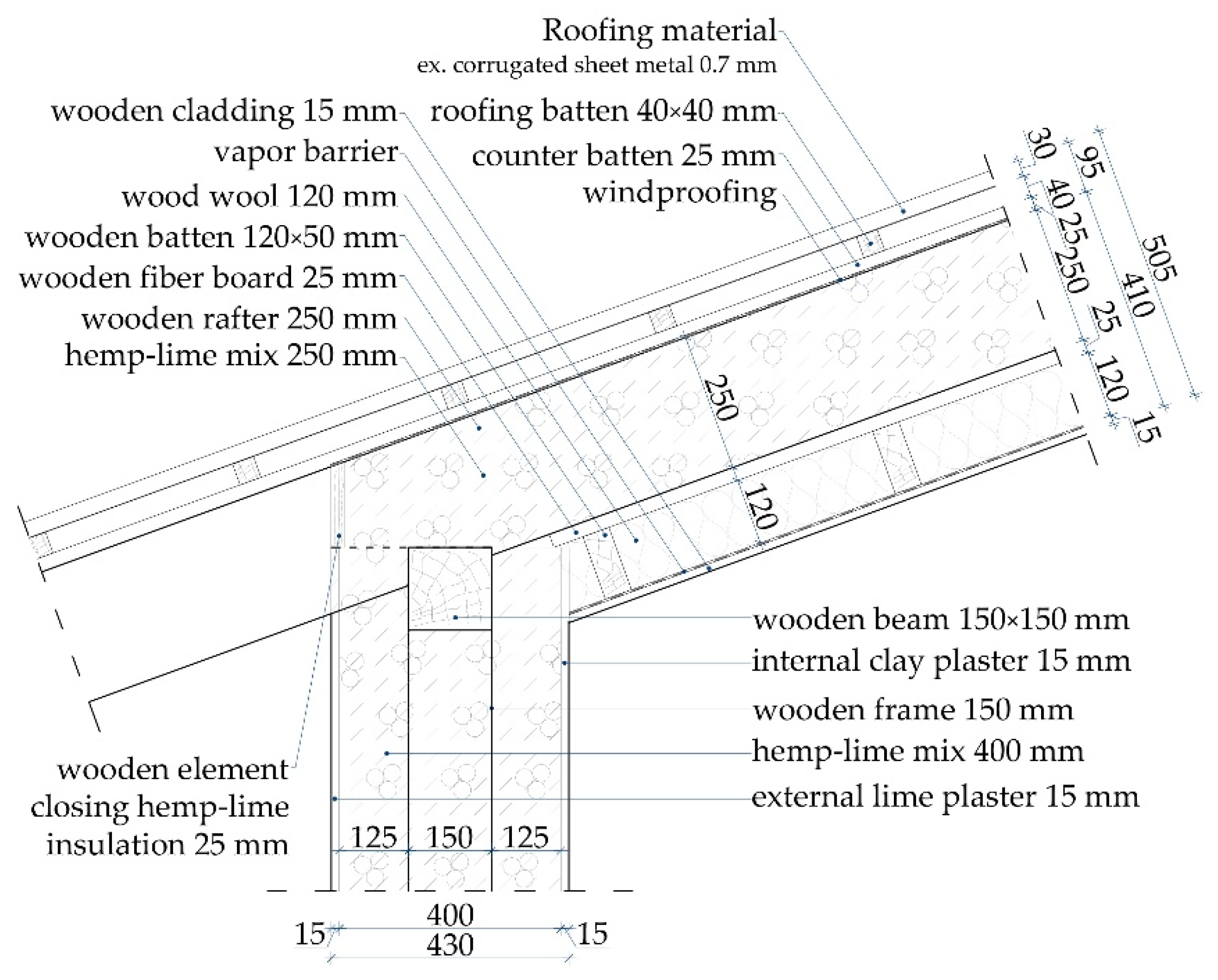
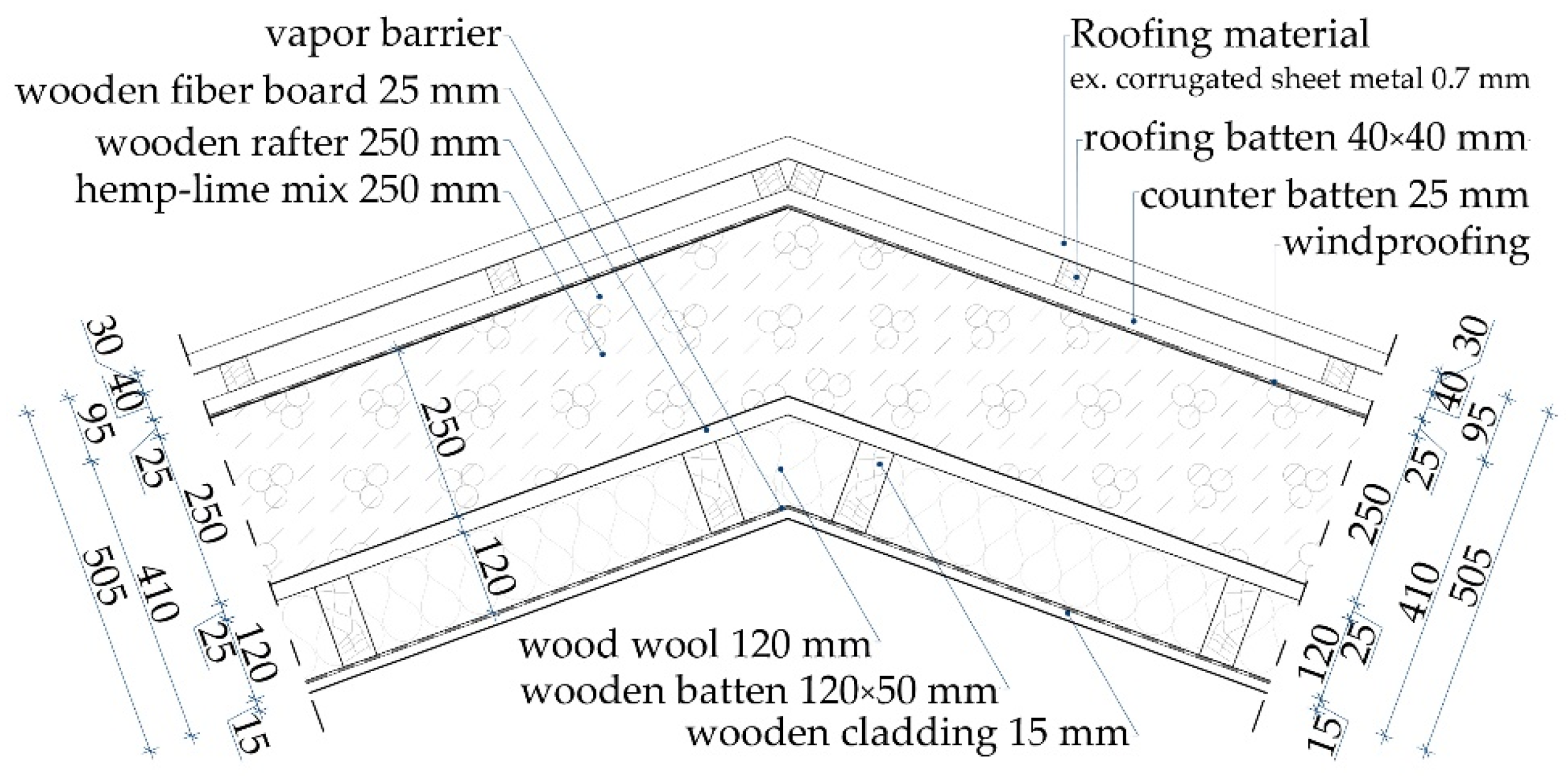
2.1. Junctions Used in Calculations
2.2. Simulations
2.2.1. Calculation Method
2.2.2. Materials’ Properties and Boundary Conditions Used in Calculations
3. Results and Discussion
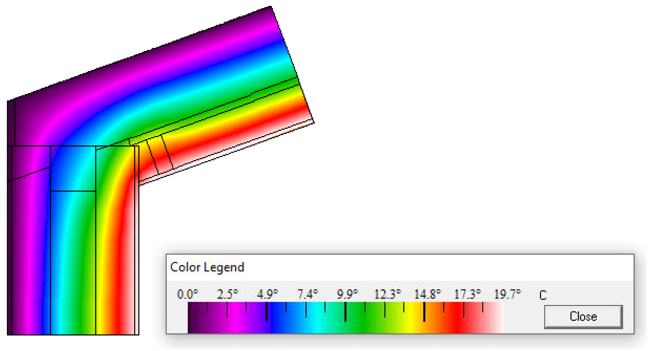
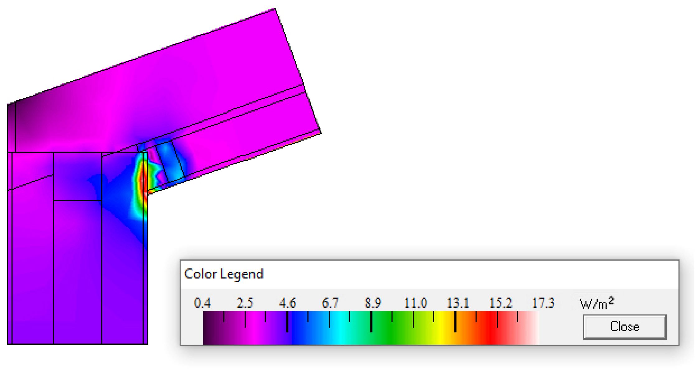
3.1. Linear Thermal Transmittance of the Analysed Bridges
3.2. Heat Losses through an Exemplary Roof
4. Conclusions
- The smaller tilt of a roof is a factor diminishing heat transfer through the main part of the construction;
- Even though they increase the heat transfer through the linear bridges, their influence is of minor importance in this case;
- As the share of the thermal bridges in the total heat losses may be up to 15%, the above statement does not justify the negligence of carefully designing the construction junctions, especially in low-energy buildings;
- Through the analyses of heat transfer in specific junctions, it is possible to identify weak points in construction and substitute them with an alternative, better design.
Author Contributions
Funding
Data Availability Statement
Conflicts of Interest
References
- Alhavari, A.; Mukhopadhyaya, P. Thermal Bridges in Building Envelopes an Overview of Impacts and Solutions. Int. Rev. Appl. Sci. Eng. 2018, 9, 31–40. [Google Scholar] [CrossRef]
- Building Performance Institute Europe (BPIE). Renovation Strategies of Selected EU Countries: A Status Report on Compliance with Article 4 of the Energy Efficiency Directive; BPIE: Brussels, Belgium, 2014; Available online: https://bpie.eu/wp-content/uploads/2015/10/Renovation-Strategies-EU-BPIE-2014.pdf (accessed on 21 November 2023).
- Yuan, X.; Wang, X.; Zuo, J. Renewable energy in buildings in China—A review. Renew. Sustain. Energy Rev. 2013, 24, 1–8. [Google Scholar] [CrossRef]
- Brzyski, P.; Grudzińska, M.; Majerek, D. Analysis of the Occurrence of Thermal Bridges in Several Variants of Connections of the Wall and the Ground Floor in Construction Technology with the Use of a Hemp–Lime Composite. Materials 2019, 12, 2392. [Google Scholar] [CrossRef]
- Pérez-Lombard, L.; Ortiz, J.; Pout, C. A review on buildings energy consumption information. Energy Build. 2008, 40, 394–398. [Google Scholar] [CrossRef]
- The United Nations. Paris Agreement. 2015. Available online: https://unfccc.int/sites/default/files/english_paris_agreement.pdf (accessed on 21 November 2023).
- European Parliament. Directive 2002/91/EC of the European Parliament and of the Council of 16 December 2002 on the Energy Performance of Buildings. Off. J. Eur. Union 2003, 46, 65–71. Available online: https://eur-lex.europa.eu/LexUriServ/LexUriServ.do?uri=OJ:L:2003:001:0065:0071:en:PDF (accessed on 21 November 2023).
- European Parliament. Directive 2023/955/EU of the European Parliament and the Council of 30 May 2018 on the Energy Perfromance of Buildings. Off. J. Eur. Union 2023. Available online: https://eur-lex.europa.eu/legal-content/EN/TXT/HTML/?uri=CELEX:32023L1791&qid=1700576301961 (accessed on 21 November 2023).
- Trotta, G. Assessing energy efficiency improvements, energy dependence, and CO2 emissions in the European Union using a decomposition method. Energy Effic. 2019, 12, 1873–1890. [Google Scholar] [CrossRef]
- Theodosiou, T.G.; Papadopoulos, A.M. The impact of thermal bridges on the energy demand of buildings with double brick wall constructions. Energy Build. 2008, 40, 2083–2089. [Google Scholar] [CrossRef]
- Kotti, S.; Teli, D.; James, P.A.B. Quantifying Thermal Bridge Effects and Assessing Retrofit Solutions in a Greek Residential Building. Procedia Environ. Sci. 2017, 38, 306–313. [Google Scholar] [CrossRef]
- Evola, G.; Margani, G.; Marletta, L. Energy and cost evaluation of thermal bridge correction in Mediterranean climate. Energy Build. 2011, 43, 2385–2393. [Google Scholar] [CrossRef]
- Ilomets, S.; Kalamees, T. Evaluation of the criticality of thermal bridges. J. Build. Pathol. Rehabil. 2016, 1, 11. [Google Scholar] [CrossRef]
- Dumitrescu, L.; Baran, I.; Pescaru, R.A. The Influence of Thermal Bridges in the Process of Buildings Thermal Rehabilitation. Procedia Eng. 2017, 181, 682–689. [Google Scholar] [CrossRef]
- Brzyski, P.; Grudzińska, M.; Böhm, M.; Łagód, G. Energy Simulations of a Building Insulated with a Hemp-Lime Composite with Different Wall and Node Variants. Energies 2022, 15, 7678. [Google Scholar] [CrossRef]
- Jedidi, M.; Benjeddou, O. Effect of Thermal Bridges on the Heat Balance of Buildings. Int. J. Civ. Eng. 2018, 2, 41–49. [Google Scholar]
- Mayer, Z.; Kahn, J.; Götz, M.; Hou, Y.; Beiersdörfer, T.; Blumenröhr, N.; Volk, R.; Streit, A.; Schultmann, F. Thermal Bridges on Building Rooftops. Sci. Data 2023, 10, 268. [Google Scholar] [CrossRef]
- Cox-Ganser, J.M. Indoor dampness and mould health effects—Ongoing questions on microbial exposures and allergic versus nonallergic mechanisms. Clin. Exp. Allergy 2015, 45, 1478–1482. [Google Scholar] [CrossRef]
- Grudzińska, M.; Brzyski, P. The Occurrence of Thermal Bridges in Hemp-Lime Construction Junctions. Period. Polytech. Civ. Eng. 2019, 63, 377–387. [Google Scholar] [CrossRef]
- Borgero, S.; Chiari, A. The influence of thermal bridge calculation method on the building energy need: A case study. Energy Procedia 2018, 148, 1042–1049. [Google Scholar] [CrossRef]
- Kosiński, P.; Brzyski, P.; Tunkiewicz, M.; Suchorab, Z.; Wiśniewski, D.; Palczyński, P. Thermal Properties of Hemp Shives Used as Insulation Material in Construction Industry. Energies 2022, 15, 2461. [Google Scholar] [CrossRef]
- Meshgin, P.; Xi, Y. Multi-scale composite models for the effective thermal conductivity of PCM-concrete. Constr. Build. Mater. 2013, 48, 371–378. [Google Scholar] [CrossRef]
- Li, H.; Zeng, Q.; Xu, S. Effect of pore shape on the thermal conductivity of partially saturated cement-based porous composites. Cem. Concr. Compos. 2017, 81, 87–96. [Google Scholar] [CrossRef]
- Qiu, L.; Zou, H.; Tang, D.; Wen, D.; Feng, Y.; Zhang, X. Inhomogeneity in pore size appreciably lowering thermal conductivity for porous thermal insulators. Appl. Therm. Eng. 2018, 130, 1004–1011. [Google Scholar] [CrossRef]
- Li, K.; Li, D.; Liu, D. Meso-scale investigations on the effective thermal conductivity of multi-phase materials using the finite element method. Int. J. Heat Mass Transf. 2020, 151, 119383. [Google Scholar] [CrossRef]
- Sinka, S.; Sahmenko, G.; Korjakins, A.; Radina, L.; Bajare, D. Hemp Thermal Insulation Concrete with Alternative Binders, Analysis of their Thermal and Mechanical Properties. IOP Conf. Ser. Mater. Sci. Eng. 2015, 96, 012029. [Google Scholar] [CrossRef]
- Pietruszka, B.; Gołębiewski, M. Właściwości wyrobów budowlanych na bazie konopi. Przegląd Bud. 2019, 10, 139–141. [Google Scholar]
- Walker, R.; Pavía, S. Moisture transfer and thermal properties of hemp–lime concretes. Constr. Build. Mater. 2014, 64, 270–276. [Google Scholar] [CrossRef]
- Elfordy, S.; Lucas, F.; Tancret, F.; Scudeller, Y.; Goudet, L. Mechanical and thermal properties of lime and hemp concrete (“hempcrete”) manufactured by a projection process. Constr. Build. Mater. 2008, 22, 2116–2123. [Google Scholar] [CrossRef]
- Barnat-Hunek, D.; Smarzewski, P.; Fic, S. Mechanical and thermal properties of hemp-lime composites. Compos. Theory Pract. 2015, 15, 21–27. [Google Scholar]
- Evrard, A. Sorption behaviour of Lime-Hemp Concrete and its relation to indoor comfort and energy demand. In Proceedings of the PLEA2006—23rd International Conference on Passive and Low Energy Architecture, Geneva, Switzerland, 6–8 September 2006. [Google Scholar]
- Bevan, R.; Wolley, T. Hemp lime construction. In A Guide to Building with Hemp Lime Composites; IHS BRE Press: Bracknell, UK, 2008; ISBN 978-1-84806-033-3. [Google Scholar]
- Bevan, R.; Wolley, T. Constructing aa low energy house from hempcrete and other natural materials. In Proceedings of the 11th International Conference on Non-conventional Materials and Technologies (NOCMAT 2009), Bath, UK, 6–9 September 2009. [Google Scholar]
- Florentin, Y.; Pearlmutter, D.; Givoni, B.; Gal, E. A life-cycle energy and carbon analysis of hemp-lime bio-composite building materials. Energy Build. 2017, 156, 293–305. [Google Scholar] [CrossRef]
- Schiavoni, S.; D’Alessandro, F.; Bianchi, F.; Asdrubali, F. Insulation materials for the building sector: A review and comparative analysis. Renew. Sustain. Energy Rev. 2016, 62, 988–1011. [Google Scholar] [CrossRef]
- ISO 10211; Thermal Bridges in Building Construction. Heat Flows and Surface Temperatures. Detailed Calculations. European Committee for Standardization: Geneva, Switzerland, 2017.
- Available online: https://windows.lbl.gov/software-tools (accessed on 13 November 2023).
- Hilderson, W. Therm 7.4 Validation According to EN ISO 10211:2007. The Flemish Passive House Platform. Available online: https://pixii.be/sites/default/files/therm_7.4_validatie_10211.pdf (accessed on 13 November 2023).
- Garay, R.; Uriarte, A.; Apraiz, I. Performance assessment of thermal bridge elements into a full scale experimental study of a building façade. Energy Build. 2014, 85, 579–591. [Google Scholar] [CrossRef]
- Kempton, L.; Kokogiannakis, G.; Green, A.; Cooper, P. Evaluation of thermal bridging mitigation techniques and impact of calculation methods for lightweight steel frame external wall systems. J. Build. Eng. 2021, 43, 102893. [Google Scholar] [CrossRef]
- Ramalho de Freitas, J.; Grala da Cunha, E. Thermal bridges modeling in South Brazil climate: Three different approaches. Energy Build. 2018, 169, 271–282. [Google Scholar] [CrossRef]
- Smusz, R.; Korzeniowski, M. Experimental investigation of thermal bridges in building at real conditions. E3S Web Conf. 2018, 70, 03013. [Google Scholar] [CrossRef]
- ISO 6946; Building Components and Building Elements. Thermal Resistance and Thermal Transmittance. Calculation Methods. European Committee for Standardization: Geneva, Switzerland, 2017.
- Nagy, B. Comparative analysis of multi-dimensional heat flow modeling. In Proceedings of the 2nd Conference for PhD Students in Civil Engineering, Cluj-Napoca, Romania, 10–12 December 2014. [Google Scholar]
- ISO 10456; Building Materials and Products—Hygrothermal Properties—Tabulated Design Values and Procedures for Determining Declared and Design Thermal Values. European Committee for Standardization: Geneva, Switzerland, 2007.
- Available online: https://imgw.pl/wydarzenia/warunki-termiczne-w-polsce-w-sezonie-zimowym-20202021 (accessed on 22 December 2023).
- ISO 14683; Thermal Bridges in Building Construction. Linear Thermal Transmittance. Simplified Methods and Default Values. European Committee for Standardization: Geneva, Switzerland, 2017.
- ISO 52016-1; Energy Performance of Buildings. Energy Needs for Heating and Cooling, Internal Temperatures and Sensible and Latent Heat Loads. Part 1: Calculation Procedures. European Committee for Standardization: Geneva, Switzerland, 2017.
- Nagy, B.; Marosvölgyi, M.; Szalay, M. Comparison of thermal bridge calculation methods. Acta Polytech. CTU Proc. 2022, 38, 77–83. [Google Scholar] [CrossRef]


| Building Material | Thermal Conductivity λ [W/(m·K)] |
|---|---|
| Hemp–lime mix (wall) | 0.080 |
| Hemp–lime mix (roof) | 0.065 |
| Wood wool | 0.038 |
| Timber | 0.16 |
| Fiberboard (low density) | 0.07 |
| Lime or clay plaster | 0.70 |
| Surface | Temperature [°C] | Surface Resistance [(m2·K)/W] | Description |
|---|---|---|---|
| Internal surface of the wall | +20 | 0.13 | Heat flow horizontal, simplified * |
| Internal surface of the roof | +20 | 0.10 | Heat flow upwards, simplified * |
| External surface (walls and roof) | 0 | 0.11 | Simplified * |
| Cut-off planes | – | – | Adiabatic |
| Type of Partition | National Regulations [W/(m2·K)] | Adopted Values (Variant I) [W/(m2·K)] | Low-Energy Buildings [W/(m2·K)] | Adopted Values (Variant II) [W/(m2·K)] |
|---|---|---|---|---|
| External wall type “a” | 0.20 | 0.198 | 0.15 | 0.147 |
| External wall type “b” | 0.20 | 0.198 | 0.15 | 0.148 |
| Roof | 0.15 | 0.149 | 0.12 | 0.117 |
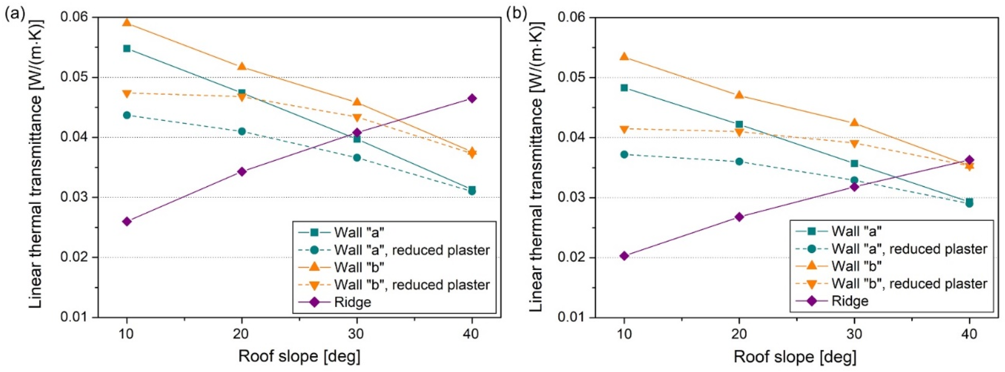
| Slope of the Roof [deg] | Linear Thermal Transmittance [W/(m·K)] | |||
|---|---|---|---|---|
| Wall with the Central Load-Bearing Frame (Variant “a”) | Wall with the Internal Load-Bearing Frame (Variant “b”) | |||
| Plaster to the Top of the Wall | Plaster to the Ceiling Level | Plaster to the Top of the Wall | Plaster to the Ceiling Level | |
| 10 | 0.055 | 0.044 | 0.059 | 0.047 |
| 20 | 0.047 | 0.041 | 0.052 | 0.047 |
| 30 | 0.040 | 0.037 | 0.046 | 0.043 |
| 40 | 0.031 | 0.031 | 0.037 | 0.037 |
| Slope of the Roof [deg] | Linear Thermal Transmittance [W/(m·K)] | |||
|---|---|---|---|---|
| Wall with the Central Load-Bearing Frame (Variant “a”) | Wall with the Internal Load-Bearing Frame (Variant “b”) | |||
| Plaster to the Top of the Wall | Plaster to the Ceiling Level | Plaster to the Top of the Wall | Plaster to the Ceiling Level | |
| 10 | 0.048 | 0.037 | 0.053 | 0.042 |
| 20 | 0.042 | 0.036 | 0.047 | 0.041 |
| 30 | 0.036 | 0.033 | 0.042 | 0.040 |
| 40 | 0.029 | 0.029 | 0.035 | 0.035 |
| Slope of the Roof [deg] | Linear Thermal Transmittance (Variant I) [W/(m·K)] | Linear Thermal Transmittance (Variant II) [W/(m·K)] |
|---|---|---|
| 10 | 0.026 | 0.020 |
| 20 | 0.034 | 0.027 |
| 30 | 0.041 | 0.032 |
| 40 | 0.047 | 0.036 |
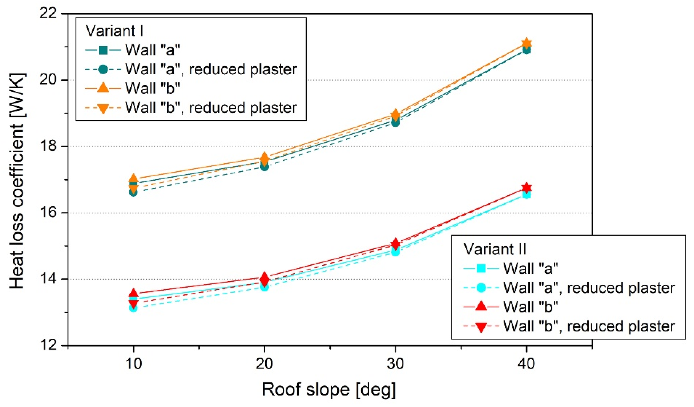
| Slope of the Roof [°] | Transmission Heat Loss Coefficient | |||||
|---|---|---|---|---|---|---|
| Wall with Plaster to the Top | Wall with Plaster to the Level of the Ceiling | |||||
| Total [W/K] | Thermal Bridges [W/K] | Thermal Bridges [%] | Total [W/K] | Thermal Bridges [W/K] | Thermal Bridges [%] | |
| 10 | 16.885 | 2.360 | 14.0 | 16.619 | 2.095 | 12.6 |
| 20 | 17.539 | 2.318 | 13.2 | 17.384 | 2.163 | 12.4 |
| 30 | 18.790 | 2.275 | 12.1 | 18.716 | 2.202 | 11.8 |
| 40 | 20.918 | 2.251 | 10.8 | 20.911 | 2.244 | 10.7 |
| Slope of the Roof [deg] | Transmission Heat Loss Coefficient | |||||
|---|---|---|---|---|---|---|
| Wall with Plaster to the Top | Wall with Plaster to the Level of the Ceiling | |||||
| Total [W/K] | Thermal Bridges [W/K] | Thermal Bridges [%] | Total [W/K] | Thermal Bridges [W/K] | Thermal Bridges [%] | |
| 10 | 17.019 | 2.494 | 14.7 | 16.739 | 2.214 | 13.2 |
| 20 | 17.675 | 2.454 | 13.9 | 17.557 | 2.336 | 13.3 |
| 30 | 18.974 | 2.460 | 13.0 | 18.915 | 2.401 | 12.7 |
| 40 | 21.111 | 2.444 | 11.6 | 21.103 | 2.436 | 11.5 |
| Slope of the Roof [°] | Transmission Heat Loss Coefficient | |||||
|---|---|---|---|---|---|---|
| Wall with Plaster to the Top | Wall with Plaster to the Level of the Ceiling | |||||
| Total [W/K] | Thermal Bridges [W/K] | Thermal Bridges [%] | Total [W/K] | Thermal Bridges [W/K] | Thermal Bridges [%] | |
| 10 | 13.399 | 1.994 | 14.9 | 13.134 | 1.729 | 13.2 |
| 20 | 13.906 | 1.954 | 14.0 | 13.758 | 1.806 | 13.1 |
| 30 | 14.878 | 1.910 | 12.8 | 14.812 | 1.844 | 12.4 |
| 40 | 16.559 | 1.901 | 11.5 | 16.551 | 1.893 | 11.4 |
| Slope of the Roof [deg] | Transmission Heat Loss Coefficient | |||||
|---|---|---|---|---|---|---|
| Wall with Plaster to the Top | Wall with Plaster to the Level of the Ceiling | |||||
| Total [W/K] | Thermal Bridges [W/K] | Thermal Bridges [%] | Total [W/K] | Thermal Bridges [W/K] | Thermal Bridges [%] | |
| 10 | 13.561 | 2.156 | 15.9 | 13.273 | 1.868 | 14.1 |
| 20 | 14.062 | 2.110 | 15.0 | 13.917 | 1.965 | 14.1 |
| 30 | 15.082 | 2.115 | 14.0 | 15.031 | 2.063 | 13.7 |
| 40 | 16.751 | 2.093 | 12.5 | 16.751 | 2.093 | 12.5 |
Disclaimer/Publisher’s Note: The statements, opinions and data contained in all publications are solely those of the individual author(s) and contributor(s) and not of MDPI and/or the editor(s). MDPI and/or the editor(s) disclaim responsibility for any injury to people or property resulting from any ideas, methods, instructions or products referred to in the content. |
© 2024 by the authors. Licensee MDPI, Basel, Switzerland. This article is an open access article distributed under the terms and conditions of the Creative Commons Attribution (CC BY) license (https://creativecommons.org/licenses/by/4.0/).
Share and Cite
Grudzińska, M.; Patyna, K.; Jabłoński, W.; Brzyski, P. Thermal Transmittance in Roof–Wall Structural Junction Areas Insulated with a Hemp–Lime Mixture. Energies 2024, 17, 316. https://doi.org/10.3390/en17020316
Grudzińska M, Patyna K, Jabłoński W, Brzyski P. Thermal Transmittance in Roof–Wall Structural Junction Areas Insulated with a Hemp–Lime Mixture. Energies. 2024; 17(2):316. https://doi.org/10.3390/en17020316
Chicago/Turabian StyleGrudzińska, Magdalena, Krystian Patyna, Wojciech Jabłoński, and Przemysław Brzyski. 2024. "Thermal Transmittance in Roof–Wall Structural Junction Areas Insulated with a Hemp–Lime Mixture" Energies 17, no. 2: 316. https://doi.org/10.3390/en17020316
APA StyleGrudzińska, M., Patyna, K., Jabłoński, W., & Brzyski, P. (2024). Thermal Transmittance in Roof–Wall Structural Junction Areas Insulated with a Hemp–Lime Mixture. Energies, 17(2), 316. https://doi.org/10.3390/en17020316