Article

Sedimentary Characteristics and Basin Evolution of a Compartmentalized Foreland Basin—Internal Ionian Zone, Western Greece †

by
Ioannis Vakalas
1,2,*,
Efthymios Tripsanas
3,
Constantinos Tzimeas
4 and
Panagiotis Konstantopoulos
5
1
School of Mining and Metallurgical Engineering, Department of Geological Sciences, National Technical University of Athens, Iroon Polytechniou 9 Str., Zografou Campus, 15773 Athens, Greece
2
Institute of GeoEnergy, Technical University of Crete Campus, 73100 Chania, Greece
3
HELPE Upstream S.A., Helleniq Energy Holdings S.A., 15125 Athens, Greece
4
Freelance Exploration Geophysicist, 4 Platonos Str., 15121 Ano Pefki, Greece
5
Energean Oil & Gas, 32, Kifissias Avenue, Atrina Center, 15125 Marousi, Greece
*
Author to whom correspondence should be addressed.
This paper is an extended version of our paper published in the Book of Abstracts (p. 267) of the 36th IAS Meeting of Sedimentology, Dubrovnik, Croatia, 6–12 June 2023.
Energies 2024, 17(2), 315; https://doi.org/10.3390/en17020315
Submission received: 9 November 2023 / Revised: 27 December 2023 / Accepted: 29 December 2023 / Published: 8 January 2024
(This article belongs to the Special Issue Subsurface Energy and Environmental Protection)

Abstract

:
This study is based on the detailed sedimentological analysis of eleven sections and one well through the late Eocene–Oligocene flysch formation of the Internal Ionian Zone (IIZ) in Western Greece. The sections are spread from the northern parts of Epirus to the north and Aitolokarnania to the south. Sedimentological data combined with biostratigraphic analyses resulted in a five-stage evolutionary model for the basin. Unit I corresponds to the lower part of the examined sections, indicating the onset of clastic sedimentation. Regarding depositional environments, it is regarded as a basin plain where lobe distal fringe accumulations occur. Unit II consists almost exclusively of heterolithic facies, marking the advance of a lobe complex system. Massive sandstone facies dominate unit III and can be considered a more proximal submarine fan system. Unit IV reflects a calm period of the basin, where mud-dominated heterolithics and hemipelagic mudstones were deposited. Hemipelagic mudstone facies with intervals of heterolithics, conglomerates, and deformed and massive sandstone facies characterize unit V. The architecture resembles a slope system incised by canyons and channels. The sand-rich intervals in Units III and V could act as the most favorable reservoir levels. In contrast, the sand-rich intervals in Unit II are considered less promising due to their higher heterogeneity.

1. Introduction

In foreland basins, gravity flow deposits are crucial in determining sedimentation and depositional environments. These flows are responsible for depositing large volumes of sediment and shaping the architecture of submarine fans. It is worth noting that such basin fills are of significant economic importance, as they are known to host some of the largest oil and gas reserves [1]. Additionally, depleted or unexplored fields have the potential to work as underground storage sites for CO2 or other gases. Various classification schemes and depositional models have been proposed to unlock submarine fan architecture and optimize the exploration and exploitation of HC accumulations. The first attempts to classify submarine fans have been made by Normark [2], Walker & Mutti [3], Ricci Lucchi [4], Nelson & Nilsen [5], Mutti [6], Ricci Lucchi [7], Hiscott, Pickering & Beeden [8], Mutti & Normark [9], Shanmugam & Moiola [10], Ghibaudo [11], and Reading & Richards [12]. An ongoing process of research and re-evaluation/re-interpretation of the first submarine fan architectural schemes has resulted in the proposal of new models that are applicable at different scales and geological settings [13,14,15,16,17,18]. With the advancement of seismic and well data quality, in combination with high-resolution outcrop data, there has been a significant improvement in our understanding of the architecture of submarine fans as well as of other depositional environments [19,20,21]. The analysis of these data has enabled us to unravel the complex processes that control the formation of the genetic elements of submarine fans, leading to a more precise and detailed understanding of their characteristics. Recent studies on submarine channels and lobe complexes have provided new insights into the processes by which sediments are spread via gravity flow. New depositional models have given us further information not only about the dispersal of submarine fans but also about the evolution of basins [22,23,24,25,26,27,28,29,30,31,32,33,34,35,36]
In Greece, submarine fan deposits occur mainly in the central and western continental areas. From a sedimentological point of view, flysch deposits were first assessed as submarine fan deposits by Piper [37]. Other researchers supported this approach by studying several exposures of flysch in the area [38,39,40,41,42,43,44,45,46]. The characterization of the study area as a foreland was introduced by Underhill [47]. The evolution of the basin is mainly controlled by crustal thickening of the lithosphere due to the advancement of the External Hellenides [45] in an NW direction [47,48]. Two rotational stages, as evidenced by palaeomagnetic data [49], contribute to today’s geological and tectonic structure of Greece.

2. Materials and Methods

The scope of the present study is to assess the paleogeographic evolution of the middle Eocene to the late Oligocene foreland basin fill based on a detailed sedimentological analysis of the exposed submarine fan deposits and to perform a gross evaluation of the potential reservoir units. Detailed sedimentological identification of deep-water facies associations was carried out at 200 locations in 11 cross-sections across the basin (Figure 1). Data acquisition included recognition of basic lithological types (sandstones, mudstones, conglomerates), bed thickness measurements, and identification of thickening and thinning trends. Structural measurements (bedding planes strike and dip, fold axes, fault planes) completed the dataset. The measured thickness of the section presented in the study was corrected in areas of extensive folding (e.g., Metsovo Section). Additionally, Gamma Ray logs and cutting descriptions from Ayios Georgios 3 well [50] were re-examined, and the results are displayed along with the studied cross sections. The well is located near Dafnoti village (Figure 1), and for the convenience of this study, it will be mentioned from now on as the Dafnoti Section. Ayios Georgios well is one of the few available subsurface data sources in the area.
The sedimentological interpretation was carried out by identifying the genetic lithological types on a bed scale. These lithological types were then grouped into discrete facies that were used as a key to recognize facies associations that corresponded to genetic elements of submarine fan deposits. Paleoflow patterns of submarine fans and dating data from previous research in the area [51,52] completed the available data set for the analysis, providing the information to identify facies associations and their distribution and potential reservoir units.

3. Geological Setting

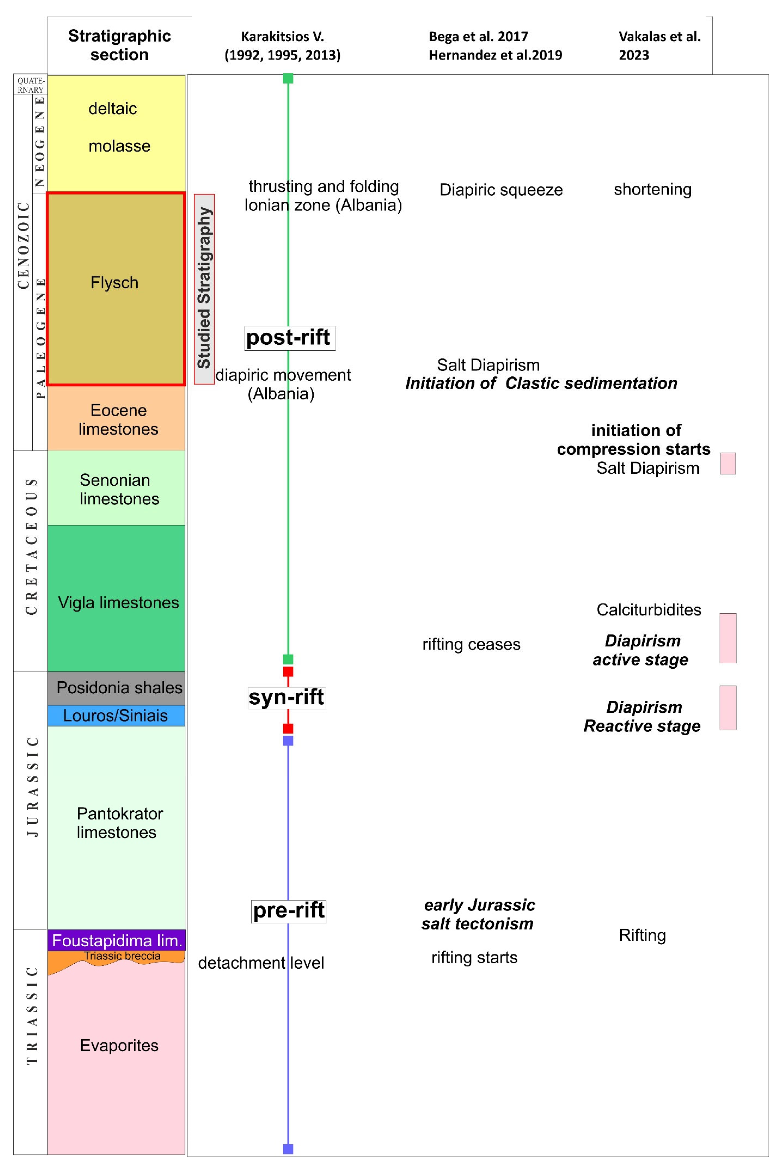
The study area (Figure 1) is part of the Ionian zone in Western Greece. The Ionian zone has been extensively studied, as it has attracted interest for hydrocarbon exploration for more than half a century. Structural, sedimentological, geochemical and paleontological studies [50,53,54,55,56,57,58,59,60,61,62,63,64,65] cover almost the whole extent of the exposed stratigraphy to evaluate the hydrocarbon potential of the Ionian zone not only in Western Greece but also in Albania and similar settings in Italy. The Ionian zone consists of sedimentary rocks ranging from Triassic evaporites to Jurassic–Upper Eocene carbonates and minor cherts and shales (Figure 2).
Thick middle Eocene [41] to Miocene flysch deposits [72] overlie the aforementioned deposits. In a regional context, the Ionian zone is one member of a series of zones (Paxos, Ionian, and Gavrovo zones) named the External Hellenides belonging to the Hellenic Thrust and Fold Belt, which is part of the Alpine Thrust and Fold Belt. The External Hellenides mainly consist of late Paleozoic–Cenozoic sedimentary rocks deposited in a series of platforms and basins located at the margins of the Tethys Ocean [73]. The Africa–Eurasia convergence in late Mesozoic/Cenozoic times, as it was expressed in the collision of the Apulia plate with Europe, resulted in the inversion of Mesozoic basins forming a series of thrust sheets (External Hellenides) [71], resulting in the formation of a foreland (Pindos Foreland). The Pindos foreland is a Paleogene basin fill trending parallel to the External Hellenides and was formed in front of the Pindos Thrust [47,74] (Figure 1). Submarine fan accumulation resulted from the deformation and uplift of the External Hellenides, which migrated westwards. During this migration, the Gavrovo and Ionian zones acted as a foreland basin [40,47,48,75]. Therefore, Gavrovo and Internal Ionian zone deposits are considered a uniform genetic system [76]. The age of Pindos’ foreland sediments is still a matter of discussion. B.P. [77] proposed an early Miocene to middle Miocene age, explaining the presence of Oligocene fauna as a product of large-scale erosion and reworking of older sediments during the Miocene. The IGSR and IFP [78] suggested a late Eocene to early Miocene age for the basin fill, while Fleury [79], Leigh [80], Wilpshaar [81] and Bellas [82] assigned it an Oligocene age. Vakalas [52] based on calcareous nannofossils originating from 11 lithostratigraphic sections across the Internal Ionian zone, proposes a middle Eocene to late Oligocene age. Avramidis [72] proposed a middle Eocene to early Miocene age, using nannofossil zones from three studied cross sections in the Klematia-Paramythia basin (middle Ionian zone). Triantaphyllou [83] proposed a late Eocene to late Oligocene age for the Internal Ionian zone flysch deposits.

4. Sedimentology

The measured sections were assembled by categorizing recurring depositional facies to propose a scheme for identifying sedimentary facies correlations.

4.1. Lithofacies

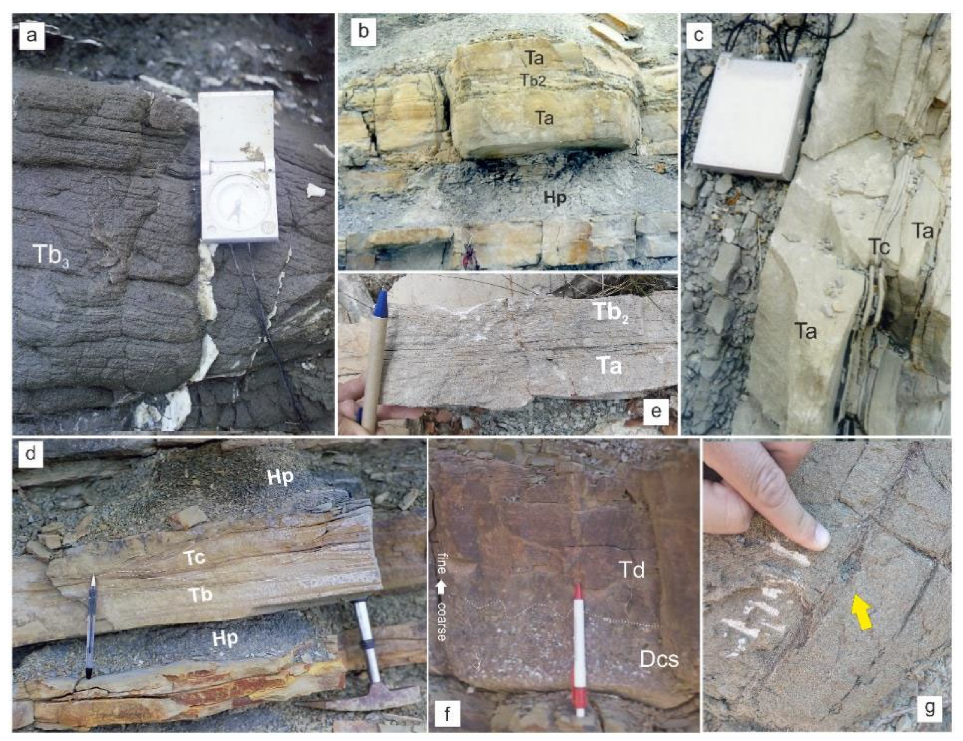
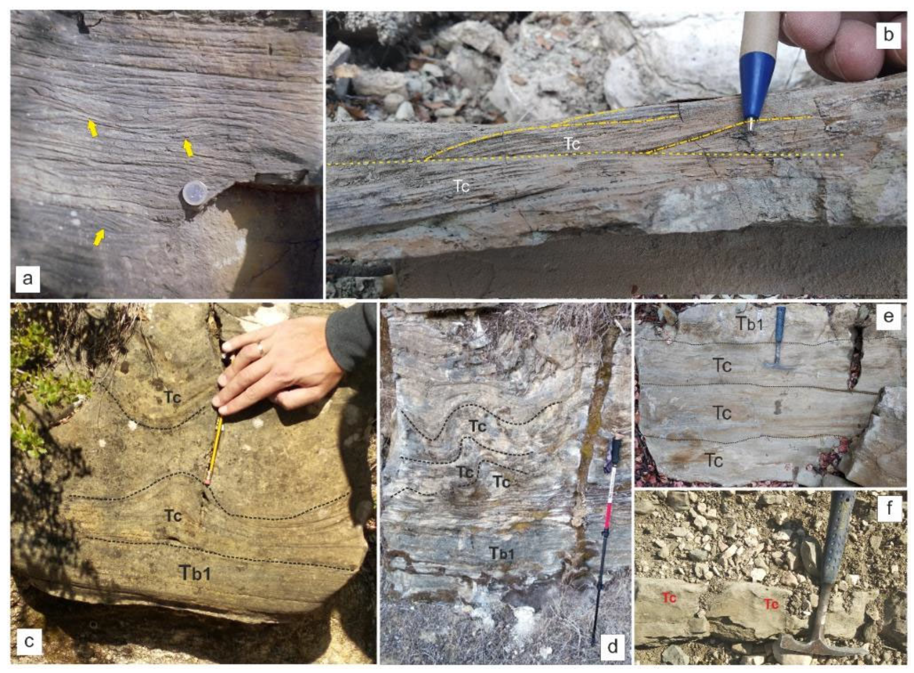
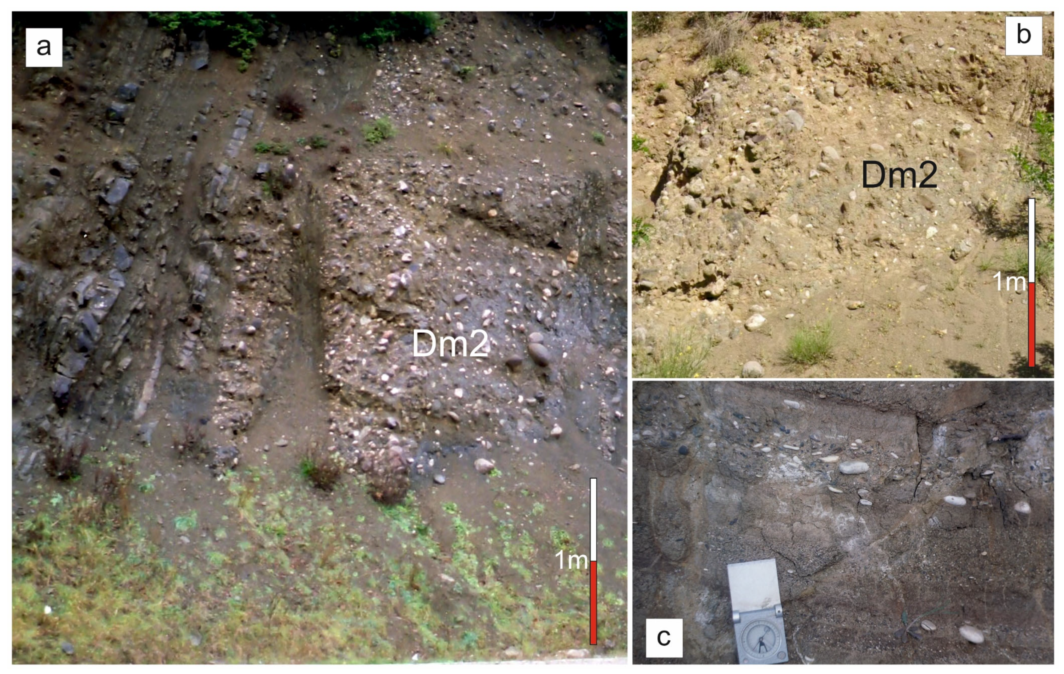
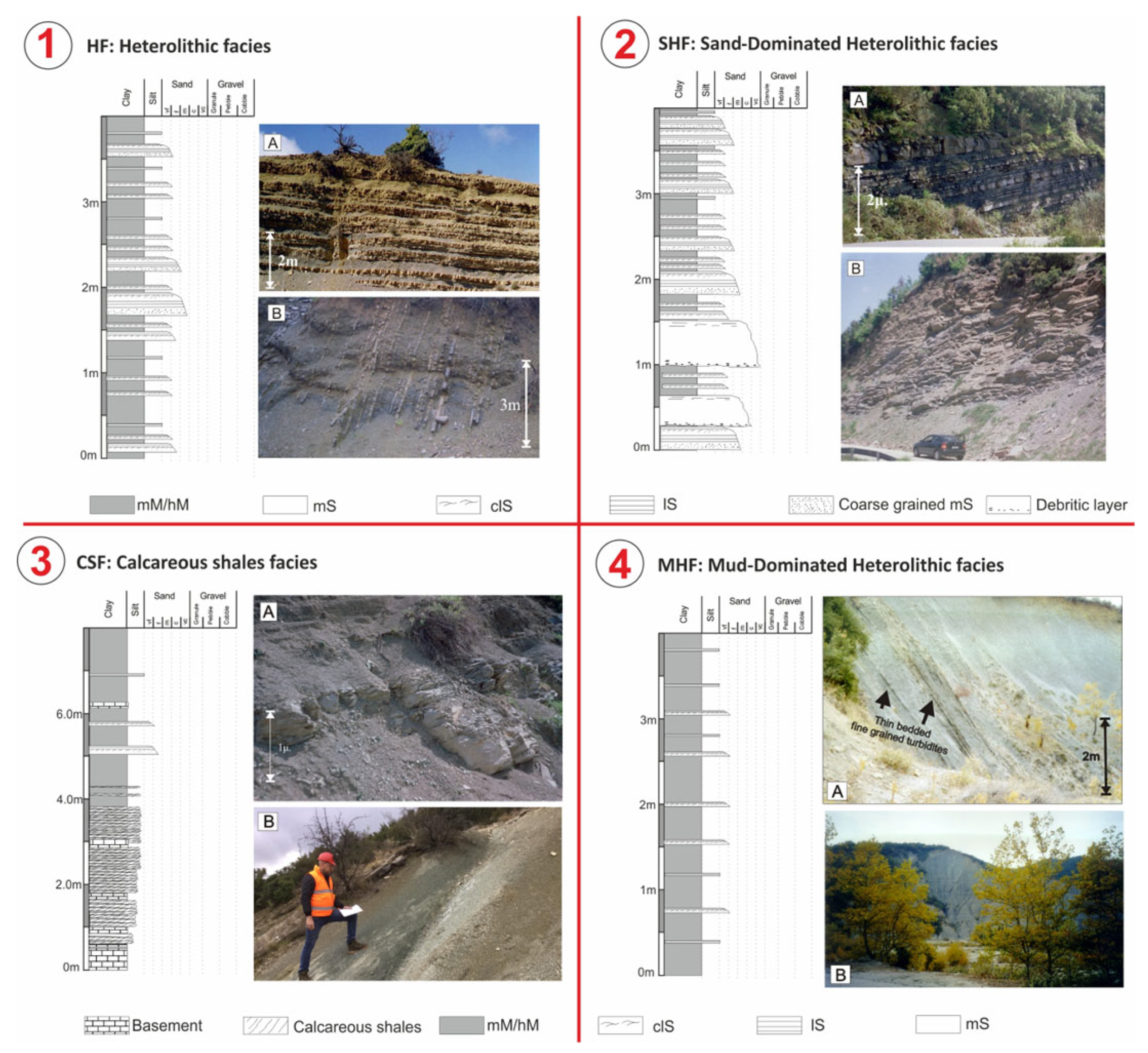
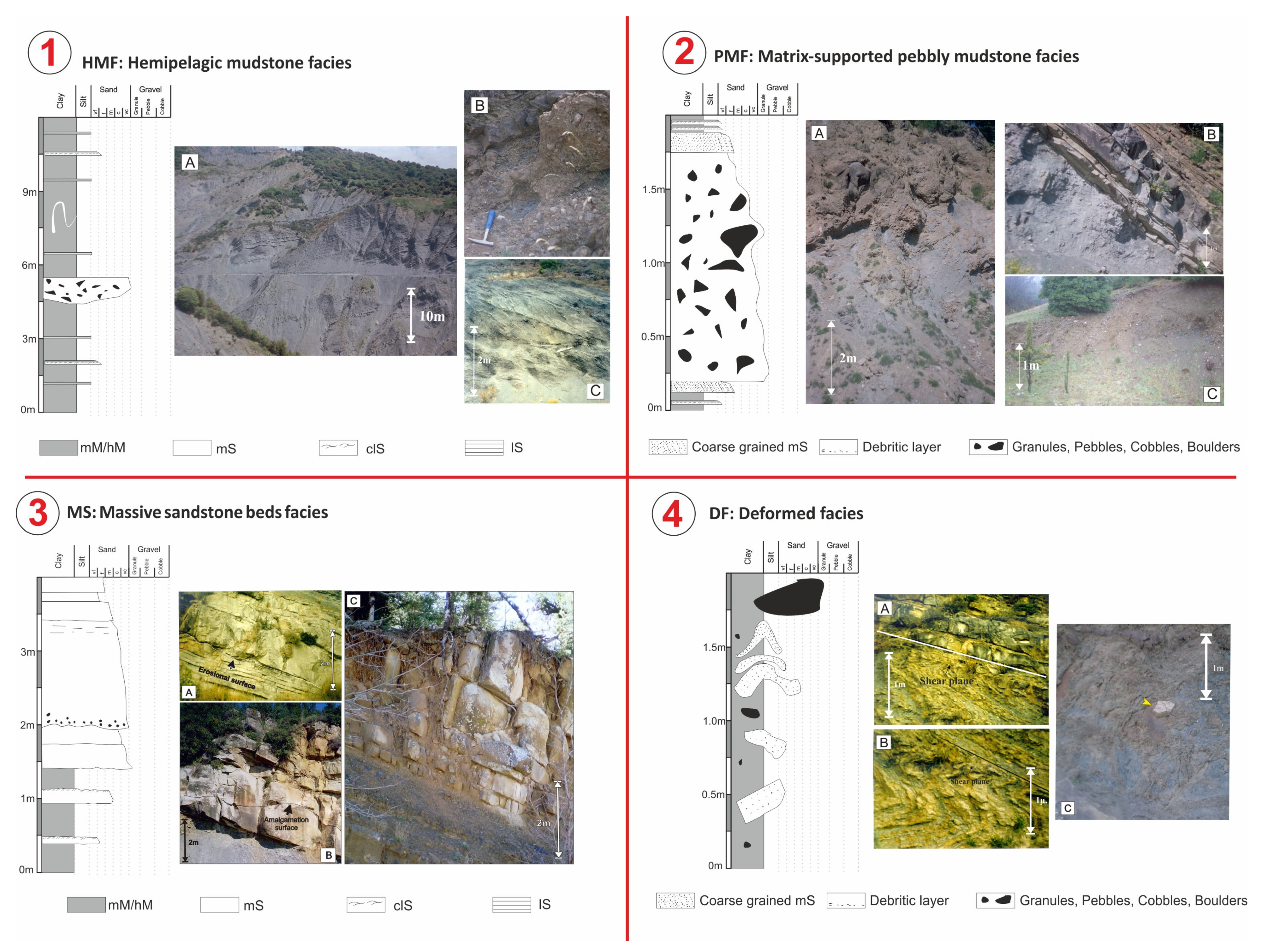
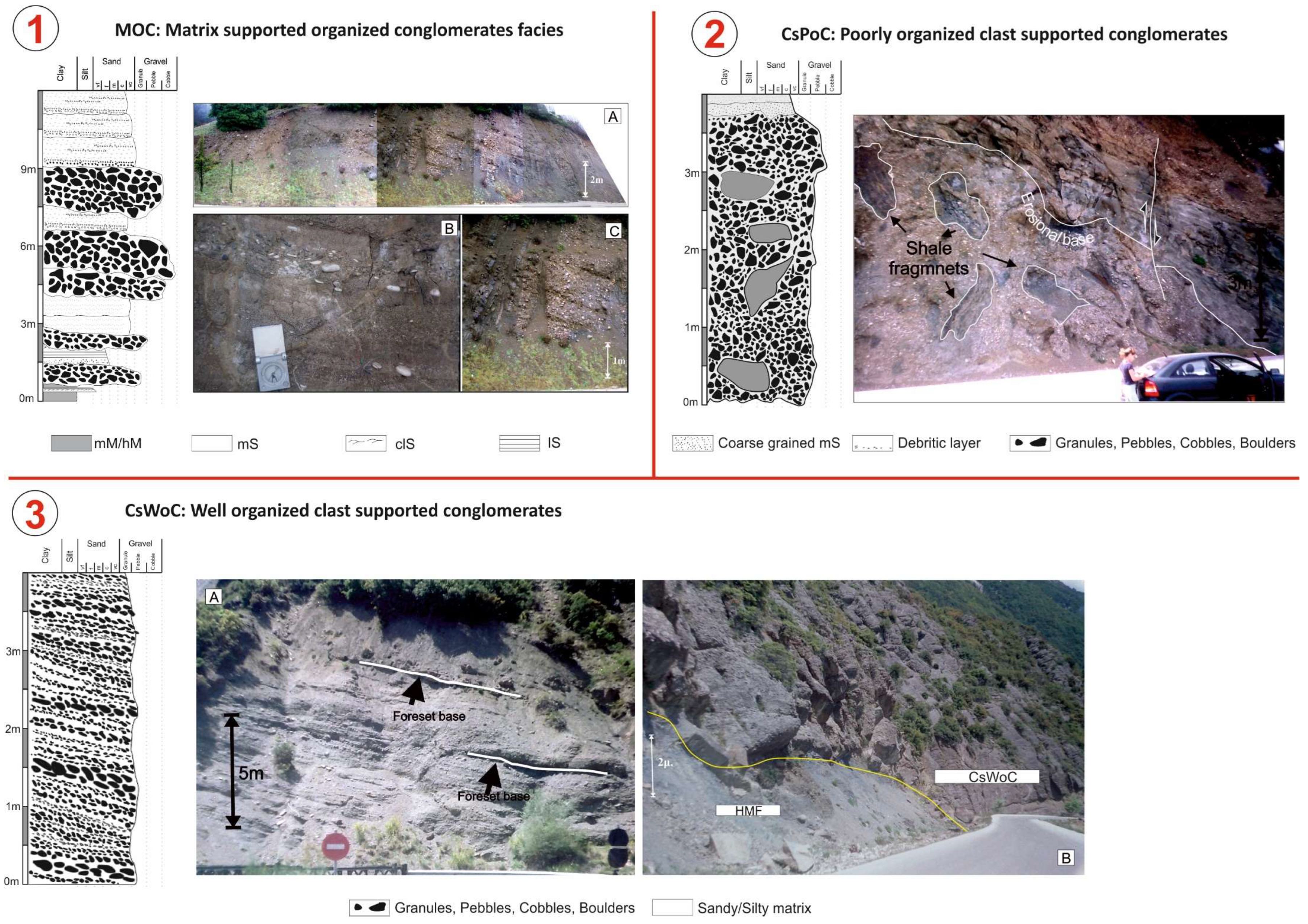
The first step was to identify distinct lithofacies to rationalize the lithostratigraphic architecture described in the previous section and construct a depositional and evolutionary model for reservoir identification. For this purpose, three major lithofacies and eight sub-lithofacies have been distinguished and documented in Table 1 and illustrated in Figure 3, Figure 4, Figure 5 and Figure 6. The flow type interpretation follows Talling’s [84] approach.

4.1.1. Mudstones

Mudstones have been distinguished in three categories: massive, laminated, and hemipelagic. Observation scale limitations make difficult further recognition of graded or ungraded mudstones in the manner proposed by Piper [37] and Talling [84].
Massive mudstone (mM): Structureless, bluish to grayish mudstone packets up to 20 m, which in places might be intercalated with intervals of very thin bedded siltstones and fine-grained sandstones (Figure 3b,d). Foraminifera and trace fossils are rare or absent. Interpretation: The structureless nature and large thickness of such lithofacies resemble homogenites, as have been described by Tripsanas [85] in the NW Gulf of Mexico, Campos et al. [86] from the Gulf of Corinth, and Mulder et al. [87] from a Cretaceous deep-sea fan sequence in the Western Pyrenees. Such lithofacies are common in foreland and confined depositional settings. However, it is impossible based on the quality of the outcrops to distinguish whether these deposits are indeed homogenites or a thick succession of distal, muddy turbidites [37,88].
Laminated mudstone (lM): Laminated mudstone beds occur either on top of sandstone beds or as intercalated intervals within massive mudstone intervals (mM). The laminations are typically less than 2 mm thick, forming layers less than 10 cm thick (Figure 3c,e). More compacted and better-preserved beds of mudstone reflect higher silt content. Silty beds with planar lamination probably correspond to interval Td, as introduced by Piper [37] (Figure 3e). In these beds, very fine sand may also be present. Abundant organic material of terrestrial origin oriented parallel to the lamination is also common (Figure 3f). Interpretation: According to Stow & Bowen [89,90] and Tripsanas [91], such lithofacies are attributed to deposition by low-density, fine-grained turbidity currents, which represent deposition from the most diluted parts and fine-grained parts of turbidity currents.
Hemipelagic mudstone (hM): Usually light grayish in color, structureless, rich in microfossils and nannoplankton [52]. The light color of hemipelagic mudstone (Figure 3a) reflects the increased content of calcareous material (calcareous organisms such as foraminifera and coccoliths). Common intercalations of sandstone and mudstone beds of gravity flow origin are observed. Interpretation: Such lithofacies are interpreted as the depositional product of hemipelagic/pelagic sedimentation by settling suspended oceanic material.

4.1.2. Sandstones

Sandstones have been categorized into massive, planar laminated, and cross laminated.
Massivesandstones (mS): This bed type is characterized by beds of >0.6 m thick fine-grained to coarse-grained sandstone. Typically, beds are structureless, with thin divisions at bed tops that grade to very fine-grained sandstone. Subtle grain-size breaks or thin discontinuity surfaces (Figure 4f) highlight amalgamation surfaces between beds. Mud clasts are common in mS lithofacies, randomly distributed or along distinct horizons. Flakes of plant material are also commonly observed throughout the mS lithofacies. Interpretation: Such beds are interpreted to be the depositional product in a layer-by-layer fashion by high-density turbidity currents (Ta) (Figure 4b,c). However, in some mud-clast rich intervals (e.g., Figure 4g) an en masse-fashion deposition by (liquefied) debris flows cannot be excluded [84,92,93,94,95,96,97].
Laminated sandstones/siltstones (lS): Laminated sandstone comprises two bed types: (a) planar-laminated sandstones and (b) ripple cross-laminated sandstones.
Planar-laminated sandstones/siltstones (plS). In most cases, planar-laminated sandstones characterize fine-grained beds. Planar-laminated sandstones may occur as individual beds or at the top of massive sandstones or the base of cross-laminated sandstones (Tb2 and Tb1 intervals in Talling [84] (Figure 4b,d,e and Figure 5c,d). The average bed thickness ranges from 0.2 to 1 m. Rarely spaced planar-laminated sand (Figure 4a) occurs with laminar bands ranging in thickness from 0.5 to 10 cm. In this case, the bed thickness may be up to 1.5 m. Each lamina is characterized by an upward trend followed by an abrupt increase in grain size as the next laminar interval is deposited. Interpretation: It is generally difficult to define the type of flow involved in forming planar-lamination exactly. In general, low-density and high-density turbidity currents can produce these sedimentary structures.
Cross-Laminated sandstones/siltstones (clS): This lithological type is mainly represented by thinner sandstone beds (up to 0.5 m), which are characterized by low-angle lamination and/or climbing current-ripple cross-lamination corresponding to the Tc interval as it was introduced by Bouma [98] (Figure 5a,b,f). These beds occur either at the tops of sandstone (mS or lS) beds or interbedded as distinct beds in mudstone lithofacies. Convolute lamination is also common (Figure 5c,d). Concerning grain size, cross-laminated sandstones are mainly fine-grained. Interpretation: There is a strong consensus based on numerous flume experiments [84] that cross-laminated sandstones have been deposited by dilute and fully turbulent flows, with relatively low rates of sediment fallout.

4.1.3. Conglomerates (Cg)

Granural, pebbly, and cobble extraformational conglomerates of a monomictic or polymictic character, depending on the source rocks. Based on the texture, two types of conglomerates have been distinguished:
Paraconglomerates (pCg): Matrix- or clast-supported, with a chaotic texture corresponding to Talling [84] Dm2 interval (Figure 6a,b), forming packets up to 15 m thick. Interpretation: Paraconglomerates are considered debris flow deposits based on their structureless and poorly sorted texture. At the top of the aforementioned structureless paraconglomerates, normal grading suggests the transformation of debris flow into turbidity currents (Figure 6a).
Orthoconglomerates (oCg): Stratified, well-sorted, clast-supported conglomerates of a monomictic or polymictic character. The stratified layers are up to 0.2 m (Figure 6c). Imbrication is also common. Interpretation: Orthoconglomerates are probably the result of deposition in a submarine deltaic environment by debris or grain flow processes [99].
Table 1. Summary of the basic bed types and their subcategories.
Bed TypesSub-CategoriesDescriptionFlow Type
MudstonesMassive mudstone (mM)Structureless, bluish-to-grayish mudstones that can form packets up to 20 mDeposition by cohesive debris flows by en masse consolidation or muddy turbidites.
Laminated mudstone (lM)Planar-laminated or cross-laminated mudstone, usually on top of sandstone beds. Laminas are typically less than 2 mm thick.Turbidites, unclear whether it is a dilute or a high concentration flow.
Hemipelagic mudstone (hM)Light grayish, structureless, rich in microfossils and nannoplanktonSettling of suspended oceanic material
SandstonesMassive sandstones (mS)>0.6 m thick beds of fine-grained to coarse-grained sandstone or pebbly sandstones. Typically, beds are structureless, with thin divisions at bed tops that grade to very fine-grained sandstone. Amalgamation surfaces between beds are highlighted by subtle grain-size breaks or thin discontinuity surfaces, usually filled with mudstone clasts. Mud clasts are deposited in distinctive horizons parallel to beds or distributed across the sandy mass.Deposition in a layer-by-layer fashion by high-density turbidity currents (TA) or in an en masse fashion by (liquefied) debris flow (DCS)
Planar-laminated sandstones/siltstones (lS)Planar-laminated sandstones with laminations that range from fine-scale (<1 mm) or thicker. In most cases, planar-laminated sandstones characterize fine-grained beds. Planar-laminated sandstones may occur as individual beds, at the top of massive sandstones, or the base of cross-laminated sandstones. Rarely spaced planar-laminated sand (Tb-3) occurs with laminar bands ranging in thickness from 0.5 to 10 cm.Low-density and high-density turbidity currents
Cross-laminated sandstones/siltstones (clS)This lithological type is mainly represented by thinner sandstone beds (up to 0.5 m), characterized by low-angle lamination and/or climbing current-ripple cross-lamination corresponding to the Tc interval, as it was introduced by Bouma [98]. These beds occur either at the tops of sandstone (mS or lS) beds or interbedded as distinct beds in mudstone lithofacies. Convolute lamination is also common.Dilute, highly turbulent flows
ConglomeratesParaconglomerates
(pCg)
Granural, pebbly, and cobble extraformational conglomerates of a monomictic or polymictic character. Build packets with thicknesses up to 20 m.Debris flows
Orthoconglomerates
(oCg)
Stratified, well-sorted, clast-supported conglomerates of a monomictic or polymictic character. Stratified layers are up to 0.2 m.Debris or grain flow processes [99]

4.2. Facies Associations

The lithological types described above are organized in recurring facies associations. These facies associations are recognized across the measured sections and in the available well logs.
CSF: calcareous shaly facies. Fine-grained, light bluish to grayish marly shales (Figure 7-3A) consisting mainly of hemipelagic mudstones (hM) interbedded with thin structureless mudstones (mM) and limestone beds (<0.2 m thick). Thin beds with discrete planar-laminated (plS) and cross-laminated sandstones (clS) are common, suggesting deposition by low-density turbidites at the more distal parts of the basin. Hemipelagic mudstones have a characteristic light color, indicative of increased carbonate content. Calcareous mudstone facies occur at the base of clastic succession, formed in a transitional environment where carbonate sedimentation gradually ceases, and an increased influx of clastic material occurs (Figure 7-3B). Diluted turbidity currents transport them and have a total thickness of 30 m.
MHF: Mudstone-Dominated Heterolithic facies. Alternations of bluish to grayish massive mudstones (mM) with very thin to thin-bedded (up to 2–3 cm) siltstones or very fine-grained sandstones (Figure 7-4A,B). Rarely, hM lithofacies are recognized. Siltstones are characterized by discrete planar lamination (plS), while sandstones are characterized by rippled tops (clS). The bases of siltstone and sandstone beds are sharp and present a good lateral extent. The sandstone/siltstone to mudstone ratio ranges from 1/2 to 2/1 (sandstone bed thickness < 0.3 m) forming packets that may exceed 100 m in thickness. These deposits usually occur at the distal fringes of turbiditic lobes or on channel over-bank areas.
HF: Heterolithic facies. Heterolithic facies consist of intercalations of sandstone beds (lS, and in a lesser degree, mS) and mudstones (mM, lM, and in a lesser degree, hM). These facies form a monotonous trend that can build units several meters thick (in some cases, more than 200 m). Sandstone beds generally present a thickness that ranges from 0.02–0.03 m to 0.3 m. Rarely, beds up to 0.5 m may occur. Thicker sandstones are characterized by a massive basinal layer that gradually passes to a laminated or rippled top. The base of the beds is generally sharp. Flute and groove marks and trace fossils of the Nereites type are common. The sandstone–mudstone ratio ranges from 1:1 (Figure 7-1B) to 3:1 (Figure 7-1A), indicating deposition at channel overbank and/or lobe fringe areas.
SHF: Sandstone-Dominated Heterolithic facies. Sandstone-dominated heterolithic facies consist predominantly of sandstone beds (<1 m thick) (mS, lS), interbedded with thin (commonly <0.2 m) beds of mM or lM. The sandstone—mudstone ratio ranges from 3:1 (Figure 7-2A) to 9:1 (Figure 7-2B). The thicker sandstone beds consist mainly of mS, which in most cases results from amalgamation processes as indicated by characteristic amalgamation surfaces. Thick mS gradually or abruptly passes upwards to lS beds and/or mudstone lithofacies. Scour marks (flutes and grooves) are common features at the base of the sandstone beds, and they are more prominent in erosive beds. Such sedimentary characteristics are characteristic of (1) the axis and off-axis parts of turbiditic lobes and (2) inner levees and proximal channel overbank areas. Sandstone-dominated heterolithic facies may form successions up to 200 m thick.
MS: Massive sandstone bed facies. Massive sandstone bed facies (Figure 8-3) consist of packets 50 to 100 m thick that mainly comprise wide (commonly > 1 m thick) mS beds. At the top of the beds, planar-laminated sandstones occur (plS and clS). The base of the beds is either erosive, characterized by poor lateral extent (Figure 8-3A), or sharp and can be traced at distances of more than 50 m (Figure 8-3C). Internally, the beds are rich in organic material and mud clasts. Grain size varies from fine-grained to coarse-grained sandstone. Pebbly sandstone lags may be present (oCg lithofacies). The presence of massive sandstones (Figure 8-3B) that gradually pass to a laminated top probably represents top-cut-out Bouma sequences and is perhaps the result of successive events that eroded the upper parts of the beds and transported finer sediment to the more distal parts of the basin. Massive sandstone beds represent deposition in a high-energy environment, such as channel fairways and channel-lobe complexes. Various gravity flow events, like high-density turbidity currents or grain flow processes, may involve sediment transport.
DF: Deformed facies. Deformed facies consist of blocks of contorted, folded, and deformed sandstone and mudstone facies of various lithological types (mS, lS, mM) (Figure 8-4A–C), with evidence of brecciation. DF facies may form 1–2 m up to 30 m thick intervals. In most cases, the blocks float in a muddy or silty matrix. These facies are recognized as separate units in HMF facies and rarely in HF ones. Similar facies have been discussed by Tripsanas [100] and are interpreted to represent landslide and debris-flow deposits.
HMF: Hemipelagic mudstone facies. Structureless, bluish to grayish mudstones consisting mainly of massive mM and hemipelagic (hM) mudstone lithofacies. Intervals of very thin to thin-bedded siltstones (up to 0.05 m) may occur, characterized by rippled top beds (clS lithofacies). HMF facies build very thick successions (more than 300 m) (Figure 8-1A) and are common in the upper stratigraphic levels of the basin.
PMF: Mud-matrix-supported pebbly mudstone facies. PMF facies consist almost exclusively of matrix-supported pebbly to cobble mudstones (pCg lithofacies) forming intervals that range in thickness from 4 to 20 m (Figure 8-2A–C). The matrix is composed mainly of grayish muddy material with a small percentage of very fine-grained sand. The average size of clasts ranges from 0.01 m to <0.25 m. Clasts are subrounded to subangular, and their composition varies, ranging from limestone deriving from the calcareous basement to cherts and sandstones originating from the deformed Pindos zone rocks [101].
The poor organization of the deposits reflects deposition by debris flow events. The subrounded subangular shape of the pebbles indicates previous reworking in a terrestrial environment before entering the marine system.
Sand-matrix and clast-supported conglomerate facies (MCF) are organized into three types:
MOC: Sand-matrix-supported organized conglomerates facies. Matrix-supported organized conglomerate facies are composed mainly of alternations of pCg (granular to pebbly concerning clast size) and with coarse-grained mS beds that, at the top, gradually pass to plS beds (Figure 9-1A,C). The conglomerates are polymictic, composed mainly of fragments of cherts, sandstones, limestones, and ophiolites. The clasts are supported by a sandy matrix and, in some cases, might be imbricated (Figure 9-1B). Sandstone beds have a thickness that ranges from 0.1 to 0.75 m. MOC facies can be recognized as 1–2 m intervals or form packets up to 10 m. Such deposits are interpreted to originate from high-density turbidity currents and grain flows. They most commonly occur in proximal channel-lobe and channel infill settings.
CsPoC: Poorly organized clast-supported conglomerates. CsPoC facies consist mainly of clast-supported, poorly sorted pCg conglomerates with extremely erosive bases, poor lateral extent, and a maximum thickness of 80 m. The clasts are 0.01 m to 0.7 m and are subrounded to subangular. At the base of the conglomerates, massive mudstone fragments (mM) showing a size of 1.5 × 2.0 m are present (Figure 9-2), pointing to the high energy of the environment and its erosive character that caused the scratching of the soft sediments of the seafloor and their enclosure in the load of the downslope-moving flow. Fluctuations in the flow energy are expressed by sandwiched massive coarse-grained sandstone beds (mS) observed in the dominant conglomeratic mass. The matrix is sandy. Erosive bases characterize internally the facies and correspond to successive high-energy flow events. This type of facies has been recognized in the northern and southern margins of the basin and corresponds to submarine canyon/valley settings. Depositional processes probably involve debris flows, traction carpets, and high-energy turbidity currents.
CsWoC: Well-organized clast-supported conglomerates. Well-organized clast-supported conglomerates are characterized by inclined downlapping planes consisting mainly of oCg lithological type (Figure 9-3A). The thickness of these conglomerates is up to 50 m (Figure 9-3B). The clasts are well rounded and platy with well-expressed imbricated texture, showing a size which ranges between 0.02 m and 0.05 m. The matrix is sandy. Clasts consist mainly of limestone fragments and, to a lesser degree, of cherts and sandstones. Small-scale erosive channels of poorly sorted matrix-supported conglomerates have been observed, showing a channelized geometry. Massive sandstone beds (mS) 15 cm thick are also present at the top of the facies. These facies probably correspond to a delta slope environment where delta foresets are developing [102,103].
Depositional processes probably involve debris flows, grain flows, traction carpets, and high-energy turbidity currents.
A summary of the proposed facies scheme is presented in Table 2.

4.3. Depositional Settings

The basin in-fill pattern comprises five different depositional settings in the study area. These settings are identified based on the participation percentage and combination of the intercalated facies associations.

4.3.1. Basinal Deposits

Basinal deposits consist exclusively of hemipelagic mudstone (HMF) and mudstone-dominated heterolithic facies (MHF), reflecting fluctuations in the influx of clastic material from the emerging foreland and proximity to the sediment entrance points in the basin floor. Such deposits appear to overlie Eocene limestones immediately, are commonly based on calcareous mudstone facies association (CSF), and can be up to 200 m thick. Basinal facies are also observed in multiple other stratigraphic intervals of the studied sections. However, they are characterized by the absence of CSF.

4.3.2. Lobe Complexes

Lobe complexes are characterized by variable facies, forming intervals ranging from 50 to 200 m thick. Vertical trends considering sandstone/mudstone ratio, bed thickness variations, grain size, bed geometry, and lateral extent are used to identify lobe complex components and depositional environment. In this effort, the scheme suggested by Prélat [104] has been applied, dividing lobe complexes into the following components: lobe axis, lobe off-axis, lobe fringe, and distal lobe fringe deposits. This fourfold division has been applied to several outcrop studies [105,106,107,108,109].
Lobe axis: Lobe axis is dominated by massive sandstone facies (MS) with rare intervals of sand-dominated heterolithic facies (SHF). Thickening and coarsening-up sandy cycles with a thickness that ranges from 1.5 to 5 m are typical. There is more than 90% involvement of sandstone beds in this setting. Mudstone of SHF facies is recognized mainly at the lower intervals of each lobe. Individual sandstone bed thickness ranges from 0.1 to 0.5 m, commonly occurring on top of each other through multiple zones of amalgamation occurring parallel to the bedding plane. Sandstone bases of both MS and SHF facies are sharp with the extended presence of flute and groove marks. Trace fossils (Nereites, palaiodictyon, thallasinoeides, Spyroraphe) are also present. Lobe axis packets form up to 10 m thick intervals.
Off-axis lobes: Off-axis lobes consist mainly of SHF facies that gradually pass to MS facies close to the lobe axis or HF facies in more distal areas. Planar- and cross-laminated sandstones of SHF facies dominate with laminated mudstone intervals. Thickening and coarsening upward cycles can still be observed, and they are 2 to 4 m thick. The contribution of the sandstone beds is lower in this setting, ranging from 50 to 90%. Off-axis lobes form packets ranging from 5 to 10 m thick.
Lobe fringe: Lobe fringe deposits comprise a range of facies depending on their location on the lobe axis. HF facies are common in the more proximal locations, consisting mainly of thin- to medium-bedded planar- and cross-laminated sandstones. To a lesser degree, massive sandstones are interbedded with laminated and massive mudstones. Bedding plane bases are sharp and planar. The participation of sandstone beds in such a setting is less than 50%. In more distal locations, the sandstone–mudstone ratio is reducing, with values ranging from 1:2 to 1:3. Lobe fringe deposits are organized into monotonously repeated packets ranging in thickness from 0.5 to 1 m. The packets may be successive or separated by intervals of HMF.
Lobe distal fringe: The lobe distal fringe environment is dominated by MHF facies where thin-bedded, and very fine sandstones and siltstones are intercalated with thin-bedded mudstones. Planar-laminated and cross-laminated sandstones are typical. In many cases, hemipelagic mudstones are recognized. Sandstone/siltstone presence is reduced to less than 20%. MHF facies of lobe distal fringe environments can form thick accumulations that exceed 150 m in thickness. Lobe distal fringe deposits gradually pass to hemipelagic facies (HMF) in more distal locations.

4.3.3. Channels and Canyons

Channels and canyons comprise a variety of facies depending on the geometrical properties and the flow types involved in the depositional processes [110,111,112].
Canyon/channel complexes: Submarine fan canyons and channel complexes crosscut slope to base of slope deposits and are characterized by dominant to rare heterolithic facies associations with intercalations of sand-matrix- and mud-matrix-supported conglomerates (PMF, CsPoC), massive sandstone (MS), and sandstone-dominated heterolithic (SHF) facies associations (e.g., upper part of Metsovo BB’ section). Strongly erosional basal surfaces characterize the coarser facies associations. Thinning and fining upward cycles of MS facies associations, which might be based on conglomeratic facies, are common within such depositional settings. Amalgamated, massive sandstone (MS) packages might be 100 m thick. Deformed facies (DF) might also be present and are interpreted as collapses of the banks of the canyons/channels. The dominance or absence of HF associations might be viewed as an indication of the bypass nature of the flows [113,114] and thus provide a criterion for the proximity of the fairways to the source area (canyons vs. channel complexes).
Channel margins, levees and overbank deposits: Channel margins, levees and overbanks consist mainly of HF facies and can form packages several meters thick. SHF and MHF facies also occur, reflecting the relevant distance from the channel axis. The sedimentological properties of the aforementioned genetic elements of channel architecture are similar to those described for lobe fringe deposits.

4.3.4. Slope Deposits

Slope deposits form a thick succession (up to 1000 m) at the upper stratigraphic levels of the measured sections. Slope deposits consist predominantly of hemipelagic mudstone facies (HMF) and mudstone-dominated heterolithic (MHF) facies associations, which might be intercalated with HF and SHF intervals and thin to thick PMF and DF packages, suggesting the proximity of steeply inclined slopes prone to sediment failures.

4.3.5. Shelf-Edge Deltas

Shelf-edge deltas were identified at the upper stratigraphic levels of the northern sections of the study area. Deltas consist mainly of well-formed foresets (15–50 cm thick) dominated by well-organized clast-supported conglomerate facies (CsWoC) that pass gradually at each cycle to massive sandstone facies (15–25 cm thick) (MS). The total thickness of shelf-edge deltas has been estimated to 50 m. The clasts are well rounded and platy with well-expressed imbricated texture, showing a size which ranges between 2 and 5 cm. The matrix is sandy. Small-scale erosive channels of poorly sorted matrix-supported conglomerates (CsPoC facies) probably indicate the transition to a canyon-channel setting.

5. Biostratigraphic Framework

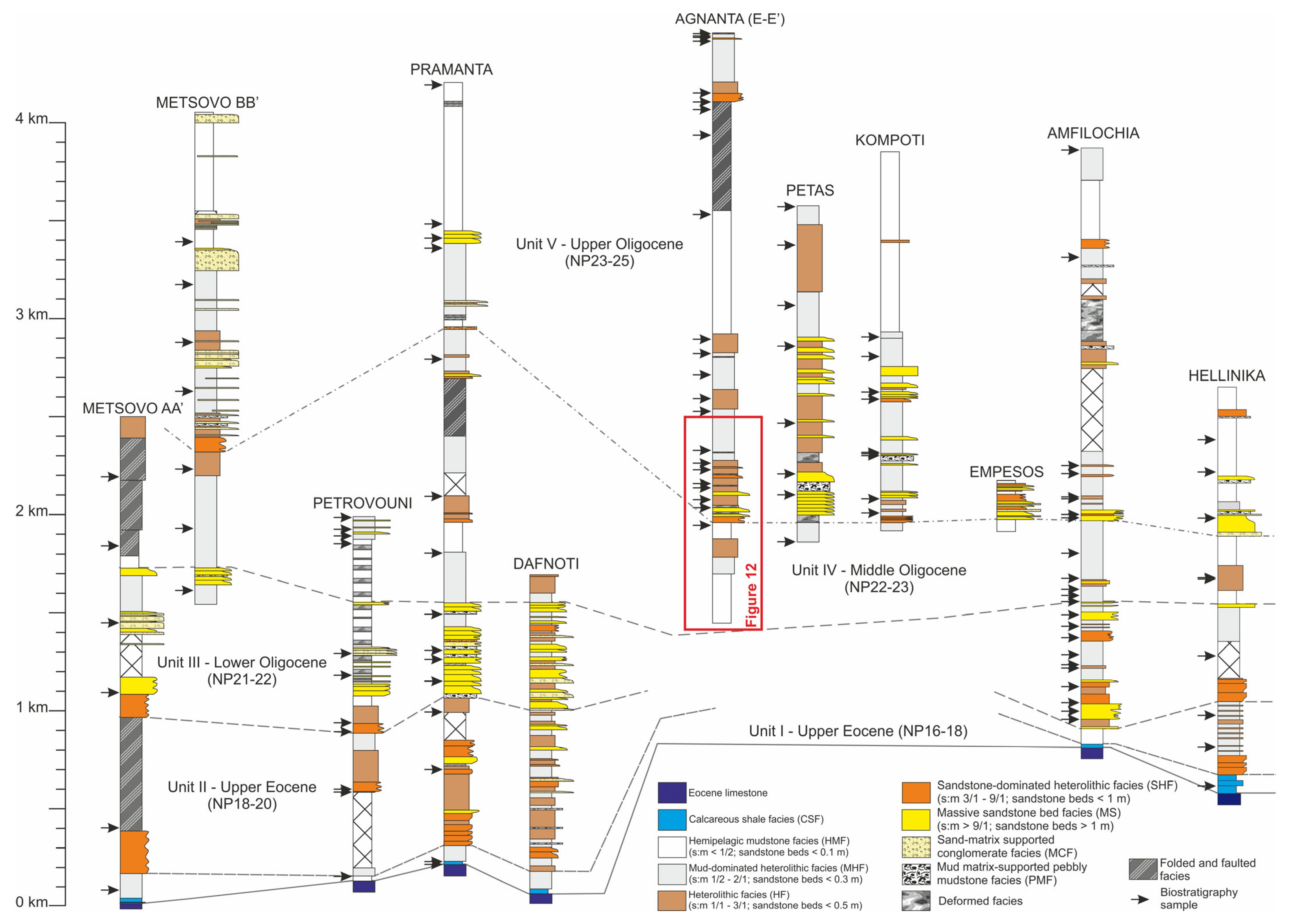
The biostratigraphic correlations presented in the next paragraph were based on the work of Vakalas [41] and Vakalas et al. [52], which cover the measured sections. The nannofossil marker species found in the samples were classified using the biozones proposed by Martini [115]. The results of the biostratigraphic analysis are presented in Figure 10 and Table 3.
The age determination of the geological cross sections was accomplished using three criteria: (1) Accept the presence of reworked fauna in most of the samples due to fine- to coarse-grained turbidites. Thus, it is accepted that the analyzed samples can be younger than the biostratigraphic analysis indicates but not older. (2) Lithostratigraphic criteria have been applied in samples with large age ranges and poor fauna to narrow the age determination. (3) In some rare occasions, lithostratigraphic criteria override biostratigraphic analysis but only assume that the samples can be younger but not older.
According to that scheme, the studied cross-sections span from the Upper Eocene to the Upper Oligocene. The Metsovo, Amphilochia, and Hellinika sections capture the entire stratigraphic interval. The Petrovouni, Palaiopyrgos, and Kavasila sections only capture the lower part of the stratigraphic interval, ranging from the Upper Eocene to Mid Oligocene. The age determination of the Dafnoti section was entirely based on its lithostratigraphic criteria due to the absence of any biostratigraphic analysis, which also yields an age range from Upper Eocene to Mid Oligocene. The lithostratigraphy in the thick (~4 km) Pramanta section displays various depositional settings, ranging from basinal to lobe to channel to slope settings. However, biostratigraphic analysis from all samples from this section points to an Upper Eocene age for the entire interval. Such great thickness and facies distribution discrepancy compared to the other cross sections suggests a significant uncertainty in the results of the biostratigraphic analysis, which could be attributed to reworked fauna. Therefore, the age determination of the Pramanta section was based almost entirely on lithostratigraphic criteria, yielding ages ranging from Upper Eocene to Upper Oligocene. The rest of the geological cross-section only captures the upper part of the stratigraphic interval of the basin, ranging from Mid to Upper Oligocene).

6. Facies Association Distribution and Stratigraphic Correlations

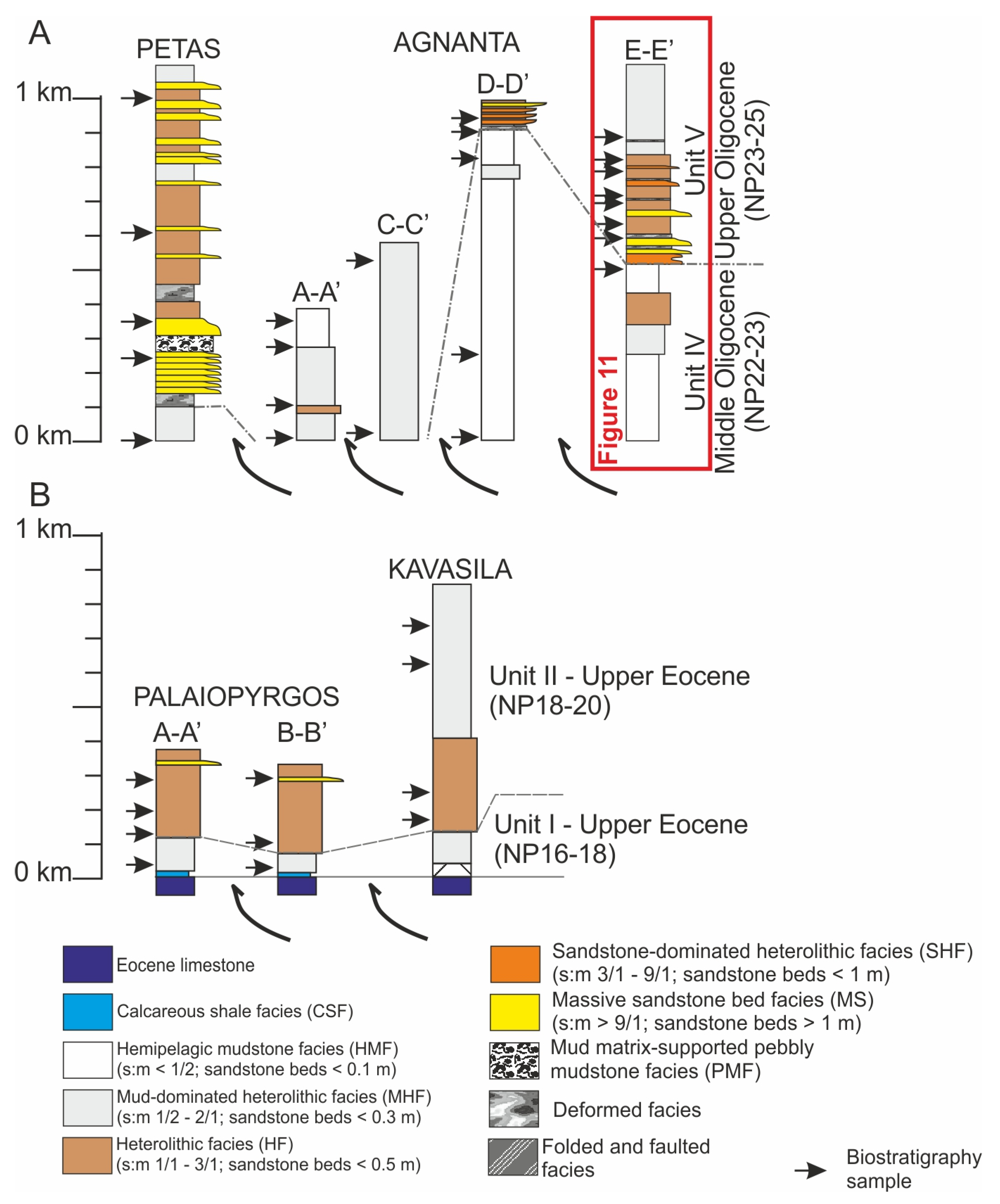
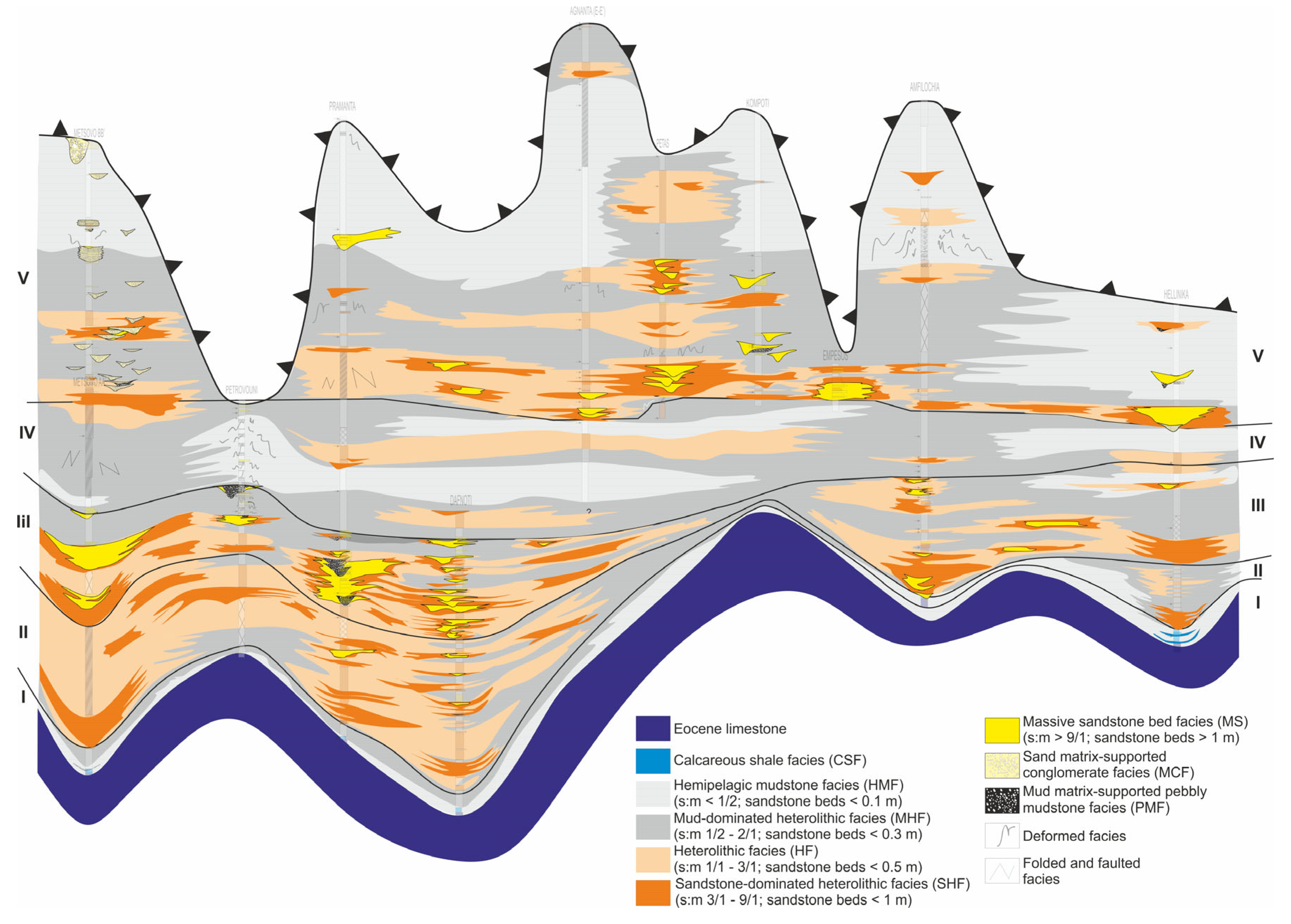
Based on the facies associations scheme described above and the available biostratigraphic data, the measured stratigraphy was distinguished into five units (Figure 11 and Figure 12).

6.1. Unit I

Unit I represents the lower part of the examined sections located stratigraphically in contact with the underlying Eocene limestones. Unit I comprises the base calcareous shaly facies (CSF), which gradually pass upwards to mudstone-dominated heterolithic facies (MHF) and have been interpreted to represent basin plain deposits with a slightly variable thickness across the studied area. In the Metsovo and Pramanta sections and the Dafnoti well, where calcareous shaly facies are well-exposed, an estimated thickness of the transitional facies (CSF) is 30 to 50 m. In Petrovouni, the thickness is reduced to less than 10 m, while in the southern parts of the basin, the thickness is restricted to 10–20 m. In the Hellinika section, CSF facies are intercalated with the mudstone-dominated heterolithics. The overlying MHF facies with an average thickness of 50–100 m are interpreted to represent the distal part of submarine fans. In the Agnanta, Petas, Kompoti, and Empesos sections, Unit I cannot be recognized since the contact of Eocene limestones with the studied submarine fans succession is covered by recent alluvials. Considering the prograding pattern of the system, Unit I represents basin plain deposits overlapped by distal lobe fringe accumulations.

6.2. Unit II

Unit II consists almost exclusively of heterolithic facies presenting the range of the introduced end members of the specific facies (mudstone-dominated heterolithics to sandstone-rich heterolithics). In the Metsovo area, Unit II comprises a total thickness of 810 m and represents a higher energy environment, where coarser sandy material is deposited in the basin. Two sub-units have been recognized in this part of the section. The first unit consists of thin-bedded heterolithic facies with sheet-like geometry of the sandstone beds and good lateral extent. The second sub-unit is characterized by SHF facies organized in repeated thickening—coarsening upwards of packets of 1.5 to 2.5 m. Even though the specific sub-unit is tectonically deformed, the geometrical properties of the beds are identifiable (sharp bases and good lateral extent). In the Petrovouni section, an estimated thickness of 850 m is expected for Unit II. The basal to middle part is not well exposed. SHF facies and HF facies are dominant in two discrete sub-units. The top of the unit is marked by 100 m of mud-dominated heterolithics. The Pramanta and Dafnoti sections depict a similar stratigraphic thickness for Unit II (800 m). In Pramanta, two sub-units of SHF facies and two of HF facies have been distinguished in the stratigraphic record, presenting similar geometrical and sedimentological properties with the SHF and HF sub-units of Petrovouni and Metsovo. Occurrences of MS facies differentiate Pramanta and Dafnoti from the northern sections. At the central part of the basin in the Amphilochia section, UNIT II is very restricted (up to 70 m) and dominated by hemipelagic facies. In the Hellinika section, Unit II comprises a total stratigraphic thickness of 600 m. It consists entirely of HF facies forming cycles of thickening and coarsening upward cycles. The geometrical properties of the sandstone beds (sheet-like geometry) resemble those described in the northern sections. In terms of depositional settings, Unit II comprises elements of a lobe complex system. MHF and HF facies correspond to lobe fringe and lobe distal fringe deposits, whereas SHF and MS facies represent off-axis and axial lobe elements.

6.3. Unit III

The main attribute of Unit III is the dominance of MS facies. In the Metsovo section, MS, SHF, HF, and sand-matrix-supported organized conglomerate (MOC) facies resembling geometrical properties of a channel system compose a stratigraphic succession of 800 m. Three distinct sub-units have been identified in this part of the section. The first sub-unit consists of SHF facies, organized in thinning and fining-upward sandstone–mudstone cycles. The second sub-unit consists of a matrix-supported fining-upward conglomerate, alternating with coarse-grained sandstone beds. The third sub-unit consists of HF facies. In the Petrovouni section, Unit III covers 700 m of stratigraphic thickness with MS facies characterized by erosive bases and poor lateral extent alternating with heterolithic facies. Deformed facies (DF) and matrix-supported fining-upward conglomerates (MOC) punctuate the increase in system energy. Hemipelagic facies intercalated with deformed facies dominate the upper parts of the unit. On the other hand, the Pramanta section is constructed by similar facies to the Metsovo section, dominated by MS, SHF, and MOC facies beds. Its thickness is slightly thinner (450 m). In the Dafnoti section, the setting is similar to Pramanta (unit thickness up to 500 m). It is uncertain how much to the south this system extends because unit III is not exposed at the central sections (Agnanta, Petas, and Kompoti). In the Amphilochia and Hellinika sections, unit III covers 550 and 450 m of the exposed stratigraphy, respectively. The main difference of Unit III in the Amphilochia and Hellinika areas, compared to the northern area, is the dominance of heterolithics and, to a lesser degree, the participation of MS facies. In the north part of the studied area (Metsovo to Dafnoti sections), unit III represents more proximal parts of submarine fan systems, especially the facies involved in channel fairway architecture. Confined MS facies correspond to channels, and the various heterolithic facies represent channel margin, levee, and overbank deposits. Deformed facies mark the steep geometry of channel flanks. MOC facies probably indicate channel lag deposits in the thalweg of channel fairways. On the other hand, to the south (the Amphilochia and Hellinika sections), Unit III consists of sedimentary facies that are more consistent with lobe complexes.

6.4. Unit IV

Unit IV, in the whole extent of the basin, is dominated by mudstone-dominated heterolithics (MHF) and hemipelagic mudstones (HMF). Rarely, HF and thin SHF facies occur in the studied section, and they are interpreted as either channel-overbank deposits in a slope or base of slope environment or distal fan facies in a coarse-grained sediment-starved depositional setting. Unit IV has a stratigraphic thickness of 600 m in the Metsovo area, while Pramanta has up to 1200 m. The thickness of the Amphilochia and Hellinika sections is restricted to 500 and 400 m, respectively. In the rest of the measured sections (Petrovouni, Agnanta, Petas, Kompoti, Empesos) and Dafnoti well, UNIT IV is only partially exposed, presenting the same characteristics and facies described previously.

6.5. Unit V

Unit V is dominated by hemipelagic mudstone facies with intervals of heterolithics, conglomerates, deformed facies, and massive sandstone facies. Unit V exposes 1700 m of stratigraphic thickness in the Metsovo area organized in two discrete sub-units. The lower sub-unit (700 m thick) consists of mudstone-dominated heterolithic facies with intervals of massive sandstones and matrix-supported conglomerates (MOC facies). MS and MOC facies are accompanied by SHF or HF facies. Deformed facies (DF) and pebbly mudstone facies (PMF) are present at various levels of the stratigraphic extent. Hemipelagic mudstone facies with intervals of MOC facies dominate the second sub-unit. The upper stratigraphic levels are dominated by hemipelagic mudstones with significant packets of poorly (CsPoC) and well-organized clast-supported conglomerate facies (CsWoC). The architecture of the stratigraphy in the Metsovo section resembles a prograding slope system where the lower sub-unit facies associations correspond to a lower-slope environment. In contrast, the second sub-unit suggests deposition in an upper-slope to shelf-edge setting according to the presence of the delta-fan CsWoC facies [102,103]. In the Pramanta section, Unit V presents a stratigraphic thickness of 1200 m assembled in two sub-units similar to the Metsovo section. The lower sub-unit (400 m) is characterized by mudstone-dominated heterolithic facies with rare intervals (a few tens up to 100 m thick) of MS and MOC facies. Deformed facies are also common, resembling a lower-slope environment. Hemipelagic mudstone facies with rare intervals of DF facies dominate the upper sub-unit. Concerning the central section measured in the basin, Unit V in the Agnanta area presents a total stratigraphic thickness of more than 1800 m. Two sub-units, similar to those in the Metsovo and Pramanta areas, compose the specific stratigraphic interval. The lower sub-unit (1100 m thick) is dominated by the whole spectrum of heterolithic facies (MHF, HF, and SHF) with some intervals of massive sandstone facies. Intercalations of deformed facies are common in this subunit. The second sub-unit (700 m) consists almost exclusively of hemipelagic mudstones. An extremely deformed zone (800 m thick) overlaps the upper sub-unit, corresponding probably to a tectonically superimposed segment of the lower sub-unit. In the Petas section, Unit V comprises HF facies intercalated with MS, PMF, and DF facies. Deformed facies and massive sandstones dominate the lower parts of the unit. In Kompoti, Unit V has similar characteristics to those presented in the Pramanta section. Two sub-units can be proposed: (a) The lower sub-unit consists of sand-dominated HF facies alternating with mud-dominated HF facies. MS facies accompanied by MOC facies are present at the upper parts of the sub-unit. The exposed thickness of the lower sub-unit was estimated to be 750 m. (b) The upper sub-unit is dominated by hemipelagic facies (1200 m thick), indicating either a diminishing coarse-grained sediment input in the area or an intense bypass with no deposition. In Figure 12 (the Petas–Agnanta A-A; C-C’, D-D,’ and E-E’), a series of cross sections showing the lower interval of Unit V is presented moving from the west to the east in the Petas—Agnanta area. The sections are separated by eastward-dipping thrusts within the flysch. Therefore, it is a safe assumption that these sections present a west–east distribution of the depositional system of the foreland basin. Interestingly, sandstone-dominated facies are only observed in the western and eastern parts of the basin, whereas mudstone-dominated facies characterize its central part. This distribution of the sandstone-dominated facies association suggests the concomitant existence of a dual channel-fairway system in the foreland basin. In the Amphilochia section, Unit V (2000 m thick) is also assembled by two sub-units with similar properties to those presented in the Kompoti section. The main difference is the presence of a significant interval (250 m) of deformed facies (DF) at the upper parts of the lower sub-unit. Mudstone-dominated heterolithic facies also dominate the top of the upper sub-unit. In the Empesos section, the lower parts of Unit V are exposed, characterized by sand-rich HF, MS, and PMF facies. In Hellinika, Unit V is characterized by a thick upper sub-unit (800 m thick) consisting mainly of hemipelagic facies. In comparison, the lower sub-unit is 200 m thick and is dominated by massive sandstones with MOC and PMF facies intervals. According to the facies association distribution described for Unit V in terms of depositional environments, it can be inferred that the specific unit represents deposition in a slope-to-shelf-edge setting [116]. Similar facies distributions have been described to occur at the slopes and basin of the active rift basin of the western Corinth Gulf during the late Quaternary [117,118,119].

7. Paleocurrent Data

Paleocurrent data (flute and groove marks) [51] was used to further analyze sediment distribution in the basin. (Figure 13). The study of the paleocurrent data provided the following concluding remarks about the sediment distribution in the basin: At the lower stratigraphic positions of the Metsovo A-A’, Petrovouni, Pramanta, Amphilochia, and Hellinika sections, the paleoflow direction is mainly towards the west. This fact, in combination with the kind of environment recognized in these stratigraphic levels (lobe complex setting), proves that the basin was not yet confined so that the flows could move unconstrained towards the west. In the Pramanta, Petas, Kompoti, and Hellinika sections, in the middle stratigraphic levels (unit III), the paleoflow regime changes parallel to the direction of the basin axis.
Considering that inner fan deposits have been recognized at these levels, it seems that the geometry of the basin must have been changing to a more trough-like character, where the confined architecture of the basin controlled the flows. The eastern margin of the trough is expressed by the Pindos thrust, and the western by the Internal Ionian thrust. In the Amphilochia section, although the flow direction is parallel to the basin axis in the western part of the section the flow shows a northeast trend, while at the eastern end, the flow trend is towards the northwest. This could be explained by different submarine fan systems in this area. At the upper stratigraphic levels of the Metsovo B-B’ section, the flow pattern is orthogonal to the Pindos thrust, probably indicating some lateral sediment sources originating from the thrust. Especially in the Metsovo section, where coarse-grained deposits have been observed, such a source point seems to be genetically related to the Kastaniotikos line [120], which, in the late Mesozoic and early Cenozoic, acted as a transform fault. The thrust activity would have increased the instability in these areas, triggering submarine failures.

8. Discussion

8.1. Basin Evolution

A five-stage basin evolutionary model is proposed based on facies associations, paleoflow patterns, and biostratigraphic correlations. Although the lower two units are captured in the Palaiopyrgos and Kavasila sections to the north, their considerable distance from the Metsovo section does not allow any direct correlation (Figure 11 and Figure 12).
Unit I (NP16–18/Middle–Late Eocene): The first stage represents the initiation of clastic sedimentation at the northern part of the basin (Palaiopyrgos, Metsovo, and Pramanta areas). Calcareous shaly facies (CSF) gradually pass to mud-dominated heterolithic facies in a basin-plain setting, declaring the arrival of clastic material from the progradation of the Fold and Thrust system in the east. The basin-plain deposits have a thickness of not more than 100 m, which is common in active continental margins [121]. Interestingly, the thickness of Unit I and the transitional zone is variable and nearly absent in the cross sections of Petrovouni and Amphilochia (Figure 14). This is a clue that the foreland basin configuration was complex, consisting of several sub-basins. Strike slips and inherited Mesozoic basin architecture could be responsible for the complex configuration of the foreland basin. Strike zones are common figures in fold and thrust settings [122,123]. The intercalations of mudstone-dominated heterolithics in the basal CSF transitional zone at the Hellinika cross section (Figure 14 and Figure 15), combined with its much larger thickness, indicate the proximity of this location to lobe complexes. This contradicts the more basinal facies at the central and north part of the study area, suggesting differences in the depositional settings along the foreland basin through the very initial stages of its formation (Figure 15a).
Unit II (NP18–20/late Eocene): At this stage, the advance of submarine fan deposits in the northern part of the basin is evidenced by sand-rich heterolithic facies corresponding to lobe fringe, off-axis lobes, and axial lobes. The paleoflow pattern points towards the west, indicating an unconfined, widespread foreland basin (Figure 13). Lobe axis deposits are most common in the cross sections of Pramanta and Dafnoti. In contrast, off-axis and fringe lobe deposits are more dominant to the north (Figure 15). It is striking that the off-axis and fringe lobe deposits at the Hellinika cross-section are separated from the northern depocenter by the basinal deposits in the Amphilochia cross-section. This is interpreted by the potential existence of a basinal high, which separated two major depocenters in the foreland basin (Figure 14). Gravity flows always follow topographic depressions, which leads to the domination of hemipelagic sedimentation on structural highs. Unit II sand-rich heterolithics have also been described by Botziolis [38] southwards of the Amphilochia section.
Unit III (NP21–22/Early Oligocene): Channel sandstones and conglomerates are dominant in the northern of the foreland basin, extending from the Metsovo to Dafnoti sections (Figure 14 and Figure 15). However, more mixed facies are observed in the Petrovouni section, where thinner sandstone and conglomerate packages and deformed facies are intercalated within hemipelagic sedimentary facies. Such facies associations are typical in slope settings. This indicates that at this time interval, the northern depocenter becomes dissected into two depocenters, one to the north expressed by the Metsovo section and one to the south defined by the Pramanta and Dafnoti sections (Figure 14). In a similar manner, the lobe complexes characterize the Amphilochia section to the south. In contrast, off-axis and fringe lobe deposits describe the Hellinika section, suggesting the presence of two additional depocenters to the south. The breaking of the initial unconfined foreland basin into multiple depocenters is attributed to the development of strike slips through the westward advancing fold and thrust system (Figure 15). The most likely candidates are the Kastaniotikos and Alevradas strike slips (Figure 15)
Paleoflow trends (Figure 13) during this time interval are oriented parallel to the elongated basin axis (NNW—SSE). The differentiation in paleoflow trends from units I and II to Unit III is attributed to the evolution of the initial unconfined foreland basin into a confined basin, with a well-expressed trough geometry with the major axis trending NW–SE. This confinement is probably due to the initiation of the Gavrovo Thrust at the eastern part of the study area. The tectonic deformation of the upper part of Unit II in the Metsovo section supports such a conclusion. The only exception in the paleoflow trends is observed in the Metsovo section, where a WSW flow direction is observed. Such a flow orientation is consistent with the work of [72] suggesting an eastward sediment source for early Oligocene flysch formation in the Botsara syncline, Internal Ionian zone, to the west of the Metsovo section.
Unit IV (NP22–23/Early-Late Oligocene): The early to late Oligocene stage marks the prevalence of fine-grained deposits (Figure 14 and Figure 15d) consisting mainly of hemipelagic facies with sand-starving heterolithic facies (MHF to HF) which can be related to two factors: (a) The advancement of Gavrovo Thrust, which might have resulted in the formation of piggy-back basins to the east and, thus, in the entrapment of coarse-grained material in these depositional settings. (b) There was a significant regression event during the early to late Oligocene, expressed by a sea-level rise of 150 m [124]. Abundant deformed facies beds in the Petrovouni section indicate that, at least in this area, the gradient of slopes increased, promoting sediment failures in the nearby slopes. This is consistent with the implied Kastaniotikos strike-slip going through this region during the early Oligocene (unit III).
Unit V stage (NP23–25/Late Oligocene): The common characteristic of this unit throughout its thickness in all cross sections is the presence of rare to typical deformed and conglomeratic facies indicating proximity to steep slopes with ample slope instability events. This is the first clue of a late Oligocene placement of the Gavrovo Thrust within an incipient foreland basin. The tectonically deformed facies within the upper part of unit IV in the Metsovo and Pramanta sections support such a conclusion. Unit V consists of two upper and lower subunits (Figure 14). The large facies variability in the lower subunit among the studied cross-sections indicates the further breakage of initial foreland basins into several depocenters. Intercalations of sand-matrix conglomerates (MOC) with mudstone-dominated heterolytics, grading upwards to delta slope conglomerates (CsWoC) is consistent with a prograding slope and consistent with a feeding system to areas further to the west, as reported by the eastward sediment supply of the flysch formation in the Klimatia—Paramythia basin [72]. On the other hand, a dual channel-fairway system is documented in the Petas to Agnanta sections to the western and eastern parts of the basin, which are separated by more hemipelagic facies. Paleoflow trends in both channel fairways are northwards (Figure 15e). The feeder of the western channel fairway appears to be through the Empesos area, where typical channel sandstone and conglomerates have been documented. On the other hand, the channel fairway to the east is attributed to the emplacement of the Gavrovo Thrust within the basin, generating an SSE—NNW corridor (Figure 15e). An analog to such a tectonic setting comes from the Quaternary Ionian Basin between Lefkas and Corfu islands (Figure 16). In this area, the emplacement of a Pliocene thrust in the foreland basin has resulted in its dissection into two, a N–S-oriented basin to the west and a SSE–NNW corridor to the east, which might act as a sediment fairway from the east. Delta deposits on the hanging wall of this thrust support this theory.
The mudstone-dominated facies in the lower subunit in the Pramanta section suggest the elevation of this part of the basin by the westward-advancing fold and thrust system. However, some rare and thin conglomerates and sandstone facies indicate that this area was still partially acting as a southward feeding system.
Similarly, the mudstone-dominated facies with some rare and thin sandstone intervals in the Amphilochia section suggest the elevation of this area by the westward-advancing fold and thrust system. The presence of thick and abundant deformed and mud-matrix conglomerates upwards within unit V indicates proximity to a steepening slope with amplitude of sediment failures. On the other hand, channel complex deposits (conglomerates and massive sandstones) characterize the Hellinika section.
The upper subunit of unit V comprises hemipelagic facies with only some rare and thin intercalations of heterolithics (Figure 14). This sudden change in the depositional system is attributed to the complete advancement of the fold and thrust system and the emplacement of the Internal Ionian Thrust [72]. The tectonically deformed facies in Agnanta E-E’ section support such a conclusion. As the tectonic activity migrates westwards and the basin is transformed to a piggyback configuration, the monotonous sheet-like heterolithics could be regarded as ponded basins (Brandford, 2003). The northern and southern parts of the basin are characterized by submarine canyons that incise slope and transport sediment westwards through pathways formed by significant strike-slip zones [120,125]. Shelf-edge deltaic deposits mark the uplift and gradual transition to a shallow marine environment.
As the convergence of the African and Eurasian plates continues, sedimentation migrates westwards, where seismic profiles verify the proposed evolutionary model (Figure 16).
Figure 16. A modern analog of the proposed evolutionary model. A transfer zone favoring the transportation of sediments at the deeper parts of the basin. Deltaic facies are dominant at the shallower eastwards-located part of the basin. Notice also the segmentation of the basin due to internal thrusting, the scarp produced by the westernmost thrust, and the produced mass transport complex deposits (MTC) (Seismic profile ref.: Bellas [126]. The bathymetric map originates from the Emodnet database: https://portal.emodnet-bathymetry.eu/, accessed on 17 February 2016).
Energies 17 00315 g016

8.2. Reservoir Evaluation

The investigation of submarine fan deposits from the middle Eocene to late Oligocene within the Internal Ionian zone has demonstrated the presence of two promising reservoir units, Unit III and Unit V. At the same time, Unit II is deemed less favorable, as explained in the following paragraphs. The diverse trapping mechanisms may include salt tectonics, compressional tectonics that facilitate the development of anticlinal structures, and the primary formation of stratigraphic traps [127]. The present study focuses mainly on the primary depositional control and the geometrical relationships of the submarine fan elements.
Unit II: The expansion of sediment load from a confined canyon–channel system results in the formation of a complex lobe system. Sand-rich, sheet-like deposits describe the sedimentological profile of Unit II exposures. Sand-dominated heterolithic facies and massive sandstone beds, organized in repetitive cycles of 2.5 to 8 m, forming stacked lobe intervals of 10 to 100 m thick, could suggest a potential reservoir unit. These deposits are recognized in the northern sections (Metsovo, Petrovouni, Pramanta, and Dafnoti well) and interpreted as lobe axis to off-axis lobe elements. The lateral extent of these deposits is difficult to trace due to the physical constraints of outcrop continuity. The nature of facies associations involved in the specific unit favors the formation of a highly heterogeneous reservoir by various studies in similar settings [128]. The heterogeneity is primarily controlled by two factors: in a mesoscopic scale, heterolithic facies contribution at a vertical and lateral scale, where mudstone content ranging from 20% to 80%, reduces the net to gross values. From a microscopic point of view, massive sandstone facies are affected by the involvement of fine-grained components (silts and very fine-grained sands) that increase matrix content and reduce primary permeability. The tectonic setting may also reduce the volume of permeable reservoir units, considering that reverse faults trending NW–SE could compartmentalize the sand bodies and cut off the link with the feeding channel–canyon system. Compartmentalization is also favored by the W–E lobe axis orientation (see paleocurrent analysis), which is vertical to sub-vertical to reverse fault strikes.
Unit III: Unit III has been interpreted as the most sand-dominated interval of the measured stratigraphy, corresponding to a channel and channel–lobe system architecture. Confined sandstone bodies with clast-supported conglomeratic facies form successions up to 500 m thick with high net-to-gross values. Laterally, sand-rich to mud-dominated heterolithics corresponding to channel margin, levee, and overbank deposits stratigraphically confine the sand bodies [36] MS facies of channelized deposits are expected to be “clean” [26] compared to the MS facies of Unit II. Channel architecture, where highly permeable zones (MOC and MS facies) are intercalated with heterolithics, results in a highly heterogeneous reservoir. This architecture can result in the isolation of sandstone bodies and reduce connectivity. Various studies in similar reservoirs [129,130,131] showed that facies architecture in channel systems has a negative impact on recovery. Various techniques have been proposed to enhance production [129,132]. Concerning post-deposition effects on reservoir quality, especially the impact of tectonics, NW–SE-trending reverse faults may result in the confinement of channel fairways that, in many cases, have the same orientation in the study area. This, according to some researchers, may inhibit reservoir formation [133,134] while others suggest that at this configuration, sand- and gravel-rich reservoirs are likely to form [135].
Unit V: Unit V has been attributed to a slope-apron to slope setting. According to [22], the highest concentration of reservoirs along muddy slopes occurs across mid-slope and toe-of-slope regions in a variety of accommodation types, including ponded, healed-slope, and incised submarine valleys, which seems to be the case in the study area. Unit V comprises two potential reservoir sub-units. The lower sub-unit resembles Unit III properties. Although sand and conglomerate percentages are higher, the steep geometry of the channels favors the development of DF facies with increased mud content that can act as flow barriers [22,24,26]. The upper sub-unit consists mainly of various conglomeratic facies confined by extended hemipelagic mudstone facies. Conglomerates are deposited in the axis of canyons, cutting the slope. Facies involved in canyon architecture again introduce primary constraints in reservoir quality due to the type of matrices for both matrix- and clast-supported conglomeratic types. Mud clasts of significant size reduce the overall porosity, especially at canyon thalwegs. Tectonically, the orientation of canyons is vertical to sub-vertical to the major reverse fault systems, favoring the segmentation of and the reduction in reservoir volumes.

8.3. Correlation with Mesozoic Ionian Zone Petroleum System

The Ionian Zone flysch has been regarded as part of the Ionian Zone petroleum system [67], playing the role of a sealing unit and favoring the formation of anticlinal traps. The main reservoirs in Western Greece consist of the Upper Cretaceous to Eocene carbonates, which have an estimated thickness of 300–700m [67]. Eocene carbonates pass gradually to flysch. Fracture and vuggy porosity describe the main attributes of the aforementioned carbonate reservoirs in the area, as also identified by studies in the extent of the Ionian zone in Albania [136,137]. The literature has underexplored the sealing capacity and integrity of the middle Eocene to Oligocene flysch of the Ionian zone. In the present study, it can be implied that the extent and thickness of Unit I deposits, where calcareous hemipelagic deposits are overlapped by mud-dominated heterolithic facies (thickness up to 200 m), act as an efficient sealing formation for the Upper Cretaceous to Eocene carbonate reservoirs. The efficiency of middle Eocene to Oligocene flysch has been evaluated in terms of a producing oil field in Albania [136]. However, further analysis is required to assess the brittleness of mudstones under geostatic and tectonic stresses [138,139].
Finally, studies from the area [57] imply that middle Eocene to Oligocene flysch accumulations or its younger analogs in the middle Ionian zone [69] can be regarded as autonomous petroleum systems, where specific organic-rich mudstone intervals would play the role of source-rock horizons. The lack of sufficient subsurface data weakens verifying the hypothesis mentioned above.

9. Conclusions

The study analyzed sediment in 11 sections and a well in Western Greece’s Internal Ionian Zone during the late Eocene–Oligocene period.
The measured sections were systematically assembled by categorizing recurring depositional facies into groups. This helped identify sedimentary facies correlations and propose a facies associations scheme for submarine fan environments. Using three basic bed types and eight subcategories, 11 facies were proposed to assemble facies associations. The proposed facies can be correlated into five distinct units. Unit I lies stratigraphically in contact with the underlying Eocene limestones and is regarded as a basin plain where lobe distal fringe accumulations occur. Unit II comprises heterolithic facies and suggests deposition in a lobe complex system. Unit III is dominated by massive sandstone facies, and Unit IV is dominated by mud-dominated heterolithics and hemipelagic mudstones. Unit V has hemipelagic mudstone facies with intervals of heterolithics, conglomerates, deformed facies, and massive sandstone facies, resembling a slope system incised by canyons and channels.
A five-stage evolutionary model is finally proposed based on facies distribution, paleocurrent data, and biostratigraphic correlations. The initial stage highlights the beginning of clastic sedimentation due to the emergence of the thrust and fold belt. The second stage is marked by the advance of lobe complex deposits succeeded by the channel fairways of the third stage. The gradual compartmentalization of the basin is recorded due to (a) internal thrusting and (b) strike-slip faulting. In the fourth stage, muddy deposits accumulate due to either the advance of mud-rich slope deposits or significant sea-level rise. The compartmentalization of the basin characterizes the fifth stage into three zones. The central part of the basin is isolated, and sediment supply is reduced as the major Pindos thrust gradually ceases. In contrast, the northern and southern parts of the basin are incised by submarine canyons transporting sediments westwards through pathways formed by major strike-slip zones.
Regarding reservoir characterization, sand-rich Units III and V are the most favorable. At the same time, Unit II is less promising due to the high heterogeneity resulting in expected lower net-to-gross values.

Author Contributions

Conceptualization: I.V. and E.T.; methodology: I.V. and E.T.; visualization: I.V. and E.T.; validation: I.V., E.T., C.T. and P.K.; data curation: I.V., E.T., C.T. and P.K.; data validation: I.V., E.T., C.T. and P.K.; writing—original draft preparation: I.V., E.T. and C.T.; writing—review and editing: I.V., E.T., C.T. and P.K. All authors have read and agreed to the published version of the manuscript.

Funding

This research received no external funding.

Data Availability Statement

Data is contained within the article.

Acknowledgments

All the authors would like to thank the reviewers for their constructive comments. Additionally, the corresponding author would like to thank A. Zelilidis, N. Kontopoulos, and especially David J.W. Piper for their support during the acquisition and initial interpretation of the sedimentological data in the context of his Ph.D. thesis.

Conflicts of Interest

The authors declare no conflicts of interest.

References

  1. Weimer, P.; Pettingill, H.S. Global Overview of Deep-Water Exploration and Production; AAPG Datapages: Tulsa, OK, USA, 2007. [Google Scholar]
  2. Normark, W.R. Growth patterns of deep-sea fans. AAPG Bull. 1970, 54, 2170–2195. [Google Scholar]
  3. Walker, R.G.; Mutti, E. Part IV. Turbidite Facies and Facies Associations; AAPG Datapages: Tulsa, OK, USA, 1973. [Google Scholar]
  4. Ricci-Lucchi, F. Depositional cycles in two turbidite formations of northern Apennines. J. Sediment. Res. 1975, 45, 3–43. [Google Scholar] [CrossRef]
  5. Nelson, C.H.; Nilsen, T.H. Modern and Ancient Deep-Sea Fan Sedimentation; SEPM Society for Sedimentary Geology: Tulsa, OK, USA, 1984. [Google Scholar]
  6. Mutti, E. Turbidite systems and their relations to depositional sequences. Proven. Arenites 1985, 148, 65–93. [Google Scholar]
  7. Ricci Lucchi, F. The Oligocene to Recent foreland basins of the northern Apennines. Foreland Basins 1986, 103–139. [Google Scholar] [CrossRef]
  8. Hiscott, R.; Pickering, K.; Beeden, D.R. Progressive filling of a confined Middle Ordovician foreland basin associated with the Taconic Orogeny, Quebec, Canada. Foreland Basins 1986, 8, 307–325. [Google Scholar]
  9. Mutti, E.; Normark, W.R. Comparing examples of modern and ancient turbidite systems: Problems and concepts. Mar. Clastic Sedimentol. Concepts Case Stud. 1987, 1–38. [Google Scholar] [CrossRef]
  10. Shanmugam, G.; Moiola, R.J. Submarine fans: Characteristics, models, classification, and reservoir potential. Earth-Sci. Rev. 1988, 24, 383–428. [Google Scholar] [CrossRef]
  11. Ghibaudo, G. Subaqueous sediment gravity flow deposits: Practical criteria for their field description and classification. Sedimentology 1992, 39, 423–454. [Google Scholar] [CrossRef]
  12. Reading, H.G.; Richards, M. Turbidite systems in deep-water basin margins classified by grain size and feeder system. AAPG Bull. 1994, 78, 792–822. [Google Scholar]
  13. Shanmugam, G.; Moiola, R.; Damuth, J. Eustatic control of submarine fan development. In Submarine Fans and Related Turbidite Systems; Springer: Berlin/Heidelberg, Germany, 1985; pp. 23–28. [Google Scholar]
  14. Shanmugam, G. The Bouma sequence and the turbidite mind set. Earth-Sci. Rev. 1997, 42, 201–229. [Google Scholar] [CrossRef]
  15. Shanmugam, G.J.M.; Geology, P. 50 years of the turbidite paradigm (1950s–1990s): Deep-water processes and facies models—A critical perspective. Mar. Pet. Geol. 2000, 17, 285–342. [Google Scholar] [CrossRef]
  16. Bouma, A.H.J.M.; Geology, P. Coarse-grained and fine-grained turbidite systems as end member models: Applicability and dangers. Mar. Pet. Geol. 2000, 17, 137–143. [Google Scholar] [CrossRef]
  17. Stow, D.A.; Mayall, M.J.M.; Geology, P. Deep-water sedimentary systems: New models for the 21st century. Pet. Geol. 2000, 17, 125–135. [Google Scholar] [CrossRef]
  18. Mutti, E.; Bernoulli, D.; Lucchi, F.R.; Tinterri, R.J.S. Turbidites and turbidity currents from Alpine ‘flysch’to the exploration of continental margins. Sedimentology 2009, 56, 267–318. [Google Scholar] [CrossRef]
  19. Kassem, A.A.; Hussein, W.S.; Radwan, A.E.; Anani, N.; Abioui, M.; Jain, S.; Shehata, A.A. Petrographic and diagenetic study of siliciclastic Jurassic sediments from the northeastern margin of Africa: Implication for reservoir quality. J. Pet. Sci. Eng. 2021, 200, 108340. [Google Scholar] [CrossRef]
  20. Kassem, A.A.; Osman, O.A.; Nabawy, B.S.; Baghdady, A.R.; Shehata, A.A. Microfacies analysis and reservoir discrimination of channelized carbonate platform systems: An example from the Turonian Wata Formation, Gulf of Suez, Egypt. J. Pet. Sci. Eng. 2022, 212, 110272. [Google Scholar] [CrossRef]
  21. Shehata, A.A.; Kassem, A.A.; Brooks, H.L.; Zuchuat, V.; Radwan, A.E. Facies analysis and sequence-stratigraphic control on reservoir architecture: Example from mixed carbonate/siliciclastic sediments of Raha Formation, Gulf of Suez, Egypt. Mar. Pet. Geol. 2021, 131, 105160. [Google Scholar] [CrossRef]
  22. Barton, M.; O’Byrne, C.; Pirmez, C.; Prather, B.; Van der Vlugt, F.; Alpak, F.O.; Sylvester, Z. Turbidite Channel Architecture: Recognizing and Quantifying the Distribution of Channel-Base Drapes Using Core and Dipmeter Data; AAPG Datapages: Tulsa, OK, USA, 2010. [Google Scholar]
  23. Covault, J.A.; Sylvester, Z.; Hubbard, S.M.; Jobe, Z.R.; Sech, R.P.; Thornton, S.E. The Stratigraphic Record of Submarine-Channel Evolution. Sediment. Rec. 2016, 14, 4–11. [Google Scholar] [CrossRef]
  24. Deptuck, M.E.; Sylvester, Z.; Pirmez, C.; O’Byrne, C. Migration–aggradation history and 3-D seismic geomorphology of submarine channels in the Pleistocene Benin-major Canyon, western Niger Delta slope. Mar. Pet. Geol. 2007, 24, 406–433. [Google Scholar] [CrossRef]
  25. Di Celma, C.N.; Brunt, R.L.; Hodgson, D.M.; Flint, S.S.; Kavanagh, J.P. Spatial and Temporal Evolution of a Permian Submarine Slope Channel-Levee System, Karoo Basin, South Africa. J. Sediment. Res. 2011, 81, 579–599. [Google Scholar] [CrossRef]
  26. Eldrett, J.; Tripsanas, E.; Davis, C.; McKie, T.; Vieira, M.; Osterloff, P.; Sandison, T. Sedimentological evolution of Sele Formation deep-marine depositional systems of the Central North Sea. Geol. Soc. Lond. Spec. Publ. 2015, 403, 63–98. [Google Scholar] [CrossRef]
  27. Fildani, A.; Hubbard, S.M.; Covault, J.A.; Maier, K.L.; Romans, B.W.; Traer, M.; Rowland, J.C. Erosion at inception of deep-sea channels. Mar. Pet. Geol. 2013, 41, 48–61. [Google Scholar] [CrossRef]
  28. Gong, C.; Wang, Y.; Steel, R.J.; Peakall, J.; Zhao, X.; Sun, Q.; Hampson, G. Flow processes and sedimentation in unidirectionally migrating deep-water channels: From a three-dimensional seismic perspective. Sedimentology 2016, 63, 645–661. [Google Scholar] [CrossRef]
  29. Groenenberg, R.M.; Hodgson, D.M.; Prelat, A.; Luthi, S.M.; Flint, S.S. Flow-Deposit Interaction in Submarine Lobes: Insights from Outcrop Observations and Realizations of a Process-Based Numerical Model. J. Sediment. Res. 2010, 80, 252–267. [Google Scholar] [CrossRef]
  30. Grundvåg, S.A.; Johannessen, E.P.; Helland-Hansen, W.; Plink-Björklund, P.; Talling, P. Depositional architecture and evolution of progradationally stacked lobe complexes in the Eocene Central Basin of Spitsbergen. Sedimentology 2013, 61, 535–569. [Google Scholar] [CrossRef]
  31. Hubbard, S.M.; Covault, J.A.; Fildani, A.; Romans, B.W. Sediment transfer and deposition in slope channels: Deciphering the record of enigmatic deep-sea processes from outcrop. Geol. Soc. Am. Bull. 2014, 126, 857–871. [Google Scholar] [CrossRef]
  32. Jobe, Z.R.; Sylvester, Z.; Parker, A.O.; Howes, N.; Slowey, N.; Pirmez, C. Rapid Adjustment of Submarine Channel Architecture to Changes in Sediment Supply. J. Sediment. Res. 2015, 85, 729–753. [Google Scholar] [CrossRef]
  33. Kremer, K.; Corella, J.P.; Hilbe, M.; Marillier, F.; Dupuy, D.; Zenhäusern, G.; Girardclos, S. Changes in distal sedimentation regime of the Rhone delta system controlled by subaquatic channels (Lake Geneva, Switzerland/France). Mar. Geol. 2015, 370, 125–135. [Google Scholar] [CrossRef]
  34. Masalimova, L.U.; Lowe, D.R.; McHargue, T.; Derksen, R.; Talling, P. Interplay between an axial channel belt, slope gullies and overbank deposition in the Puchkirchen Formation in the Molasse Basin, Austria. Sedimentology 2015, 62, 1717–1748. [Google Scholar] [CrossRef]
  35. Pemberton, E.A.L.; Hubbard, S.M.; Fildani, A.; Romans, B.; Stright, L. The stratigraphic expression of decreasing confinement along a deep-water sediment routing system: Outcrop example from southern Chile. Geosphere 2016, 12, 114–134. [Google Scholar] [CrossRef]
  36. Pyles, D.R.; Strachan, L.J.; Jennette, D.C. Lateral juxtapositions of channel and lobe elements in distributive submarine fans: Three-dimensional outcrop study of the Ross Sandstone and geometric model. Geosphere 2014, 10, 1104–1122. [Google Scholar] [CrossRef]
  37. Piper, D.J.; Panagos, A.; Pe, G. Conglomeratic Miocene flysch, western Greece. J. Sediment. Res. 1978, 48, 117–125. [Google Scholar]
  38. Botziolis, C.; Maravelis, A.G.; Pantopoulos, G.; Kostopoulou, S.; Catuneanu, O.; Zelilidis, A. Stratigraphic and paleogeographic development of a deep-marine foredeep: Central Pindos foreland basin, western Greece. Marine and Petroleum Geology 2021, 128, 105012. [Google Scholar] [CrossRef]
  39. Leigh, S.; Hartley, A.J. Mega-debris flow deposits from the Oligo-Miocene Pindos foreland basin, western mainland Greece: Implications for transport mechanisms in ancient deep marine basins. Sedimentology 1992, 39, 1003–1012. [Google Scholar] [CrossRef]
  40. Avramidis, P. Depositional Environments and Hydrocarbon Potential of Tertiary Formations in Klematia-Paramythia Basin, Epirus. Ph.D. Thesis, University of Patras, Patras, Greece, 1999. [Google Scholar]
  41. Vakalas, I. Evolution of Foreland Basins in Western Greece. Ph.D. Thesis, University of Patras, Patras, Greece, 2003. [Google Scholar]
  42. Konstantopoulos, P.A.; Maravelis, A.G.; Zelilidis, A.J.T.N. The implication of transfer faults in foreland basin evolution: Application on Pindos Foreland Basin, West Peloponnesus, Greece. Terra Nova 2013, 25, 323–336. [Google Scholar] [CrossRef]
  43. Konstantopoulos, P.; Zelilidis, A. The geodynamic evolution of Pindos foreland basin in SW Greece. Epis. J. Int. Geosci. 2012, 35, 501–512. [Google Scholar] [CrossRef] [PubMed]
  44. Konstantopoulos, P.A.; Zelilidis, A. Sedimentation of submarine fan deposits in the Pindos foreland basin, from late Eocene to early Oligocene, west Peloponnesus peninsula, SW Greece. Geol. J. 2013, 48, 335–362. [Google Scholar] [CrossRef]
  45. Vakalas, I.; Zelilidis, A. Paleogeographic reconstruction of Pindos Foreland basin during Middle Eocene–Upper Oligocene. In Proceedings of the IAS 25th Meeting, Patras, Greece, 4–7 September 2007; p. 311. [Google Scholar]
  46. Pantopoulos, G.; Vakalas, I.; Maravelis, A.; Zelilidis, A. Statistical analysis of turbidite bed thickness patterns from the Alpine fold and thrust belt of western and southeastern Greece. Sediment. Geol. 2013, 294, 37–57. [Google Scholar] [CrossRef]
  47. Underhill, J.R. Neogene and Quaternary Tectonics and Sedimentation in Western Greece. Ph.D. Thesis, Cardiff University, Cardiff, UK, 1985. [Google Scholar]
  48. Clews, J.E. Structural controls on basin evolution: Neogene to Quaternary of the Ionian zone, Western Greece. J. Geol. Soc. 1989, 146, 447–457. [Google Scholar] [CrossRef]
  49. Kissel, C.; Laj, C.; Müller, C.J.E.; Letters, P.S. Tertiary geodynamical evolution of northwestern Greece: Paleomagnetic results. Earth Planet. Sci. Lett. 1985, 72, 190–204. [Google Scholar] [CrossRef]
  50. Rigakis, N.; Nikolaou, K.; Marnelis, F.; Pakos, T. The utility of oil shows in the hydrocarbon exploration of western Greece. Bull. Geol. Soc. Greece 2007, 40, 959–971. [Google Scholar] [CrossRef]
  51. Vakalas, J.; Ananiadis, G.; Mpourlokas, J.; Poulimenos, D.; Getsos, K.; Pantopoulos, G.; Avramidis, P.; Zelilidis, A.; Kontopoulos, N. Palaeocurrent directions as an indicator of Pindos foreland evolution (central and southern part), Western Greece. Bull. Geol. Soc. Greece 2001, 34, 785–791. [Google Scholar] [CrossRef]
  52. Vakalas, I.; Ananiadis, G.; Kontopoulos, N.; Stoykova, K.; Zelilidis, A. Age determination and palaeogeographic reconstruction of pindos foreland basin based on calcareous nannofossils. Bull. Hell. Geol. Soc. 2004, 36, 864–873. [Google Scholar] [CrossRef]
  53. Kamberis, E.; Kokinou, E.; Koci, F.; Lioni, K.; Alves, T.M.; Velaj, T. Triassic evaporites and the structural architecture of the External Hellenides and Albanides (SE Europe): Controls on the petroleum and geoenergy systems of Greece and Albania. Int. J. Earth Sci. 2022, 111, 789–821. [Google Scholar] [CrossRef]
  54. Atkinson, J.; Wignall, P.; Barbullushi, R. Basin Evolution and Hydrocarbon Plays in Albania American Association of Petroleum Geologists. Search Discov. 2013, 19, 10504. [Google Scholar]
  55. Kokkalas, S.; Kamberis, E.; Xypolias, P.; Sotiropoulos, S.; Koukouvelas, I. Coexistence of thin-and thick-skinned tectonics in zakynthos area (Western Greece): Insights from seismic sections and regional seismicity. Tectonophysics 2013, 597–598, 73–84. [Google Scholar] [CrossRef]
  56. Robertson, A.H.F.; Mountrakis, D. Tectonic development of the Eastern Mediterranean region: An introduction. Geol. Soc. Spec. Publ. 2006, 260, 1–9. [Google Scholar] [CrossRef]
  57. Zelilidis, A.; Piper, D.J.W.; Vakalas, I.; Avramidis, P.; Getsos, K. Oil and gas plays in Albania: Do equivalent plays exist in Greece? J. Pet. Geol. 2003, 26, 29–48. [Google Scholar] [CrossRef]
  58. Rigakis, N. Contribution to Stratigraphic Research on Wells and Outcrops of the Alpine Formations in Western Greece, in Relation to the Petroleum Generation Efficiency of their Organic Matter. Ph.D. Thesis, Athens University, Zografou, Greece, 1999. [Google Scholar]
  59. Nikolaou, C. Contribution to the Knowledge of the Neogene, the Geology of the Ionian and Pre-Apulian Zone Boundaries Relation to the Petroleum Geology Observations in Strofades, Zakynthos and Kefallonia Islands. Ph.D. Thesis, University of Athens, Athens, Greece, 1986; p. 228. [Google Scholar]
  60. Pe-Piper, G.; Piper, D.J.W.; Bourli, N.; Zelilidis, A. Evolution of sedimentary basins as recorded in silica concretions: An example from the ionian zone, western greece. Minerals 2021, 11, 763. [Google Scholar] [CrossRef]
  61. Alexandridis, I.; Oikonomopoulos, I.K.; Carvajal-Ortiz, H.; Gentzis, T.; Kalaitzidis, S.; Georgakopoulos, A.N.; Christanis, K. Discovery of a new source-rock interval within the Pantokrator Formation, Ionian Zone, western Greece: Insights from sulfur speciation and kinetics analyses. Mar. Pet. Geol. 2022, 145, 105918. [Google Scholar] [CrossRef]
  62. Karakitsios, V.; Kvacek, Z.; Mantzouka, D. The first plant megafossil in the Early Jurassic of Greece: Brachyphyllum (Coniferales) from the Lower Posidonia Beds (Toarcian) in the Ionian zone (NW Greece) and its palaeogeographic implications. N. Jahrb. Geol. Paläontol. Abh. 2015, 278, 79–94. [Google Scholar] [CrossRef]
  63. Rigakis, N.; Karakitsios, V.; Marnelis, F.; Sotiropoulos, S. Geological solutions concluded by petroleum geochemical data in Western Greece. Bull. Geol. Soc. Greece 2013, 47, 2131–2143. [Google Scholar] [CrossRef]
  64. Rigakis, N.; Karakitsios, V. The source rock horizons of the Ionian Basin (NW Greece). Mar. Pet. Geol. 1998, 15, 593–617. [Google Scholar] [CrossRef]
  65. Makri, V.I.; Bellas, S.; Moschou, G.; Pasadakis, N.J.G. An Integrated Approach for the Thermal Maturity Modeling Re-Assessment of an Exploration Well in the Hellenides Fold and Thrust Belt. Geosciences 2023, 13, 76. [Google Scholar] [CrossRef]
  66. Vakalas, I.; Kokkalas, S.; Konstantopoulos, P.; Tzimeas, C.; Kampolis, I.; Tsiglifi, H.; Pérez-Martin, R.; Hernandez-Jiménez, P.; Pita-Gutierrez, J.P. Implications of Salt Diapirism in Syn-Depositional Architecture of a Carbonate Margin-to-Edge Transition: An Example from Plataria Syncline, Ionian Zone, NW Greece. Appl. Sci. 2023, 13, 7043. [Google Scholar] [CrossRef]
  67. Karakitsios, V. Western Greece and Ionian Sea petroleum systems. AAPG Bull. 2013, 97, 1567–1595. [Google Scholar] [CrossRef]
  68. Karakitsios, V. The influence of preexisting structure and halokinensis on organic matter preservation and thrust system evolution in the Ionian Basin, northwest Greece. Am. Assoc. Pet. Geol. Bull. 1995, 79, 960–980. [Google Scholar]
  69. Karakitsios, V. Ouverture et inversion tectonique du bassin ionien (Epire, Grece). Ann. Géologiques Pays Helléniques 1992, 35, 185–318. [Google Scholar]
  70. Bega, Z.; Soto, J. The Ionian fold-and-thrust belt in Central and Southern Albania: A petroleum province with Triassic evaporites. In Permo-Triassic Salt Provinces of Europe, North Africa and the Atlantic Margins; Elsevier: Amsterdam, The Netherlands, 2017; pp. 517–539. [Google Scholar]
  71. Hernandez, P.; Pérez, R.; Pita, J.; Ponte, A.; Rubio, B.; Malmcrona, Y.; Chambers, A.; Martin, A.; Cascone, L.; Konstantopoulos, T. New structural and petroleum system models of the Ionian Zone, North-Western Greece. In Proceedings of the 15th International Congress of the Geological Society of Greece, Athens, Greece, 22–24 May 2019. [Google Scholar]
  72. Avramidis, P.; Zelilidis, A.; Kontopoulos, N. Thrust dissection control of deep-water clastic dispersal patterns in the Klematia–Paramythia foreland basin, western Greece. Geol. Mag. 2000, 137, 667–685. [Google Scholar] [CrossRef]
  73. de Graciansky, P.C.; Dardeau, G.; Lemoine, M.; Tricart, P. The inverted margin of the French Alps and foreland basin inversion. Geol. Soc. Spec. Publ. 1989, 44, 87–104. [Google Scholar] [CrossRef]
  74. Aubouin, J.; Neumann, M.J.R.d.M. Contribution al’etude stratigraphique et micropaleontologique de l’Eocene en Grece. Rev. Micropaléontologie 1959, 2, 31–49. [Google Scholar]
  75. Underhill, J.R. Late Cenozoic deformation of the Hellenide foreland, western Greece. Geol. Soc. Am. Bull. 1989, 101, 613–634. [Google Scholar] [CrossRef]
  76. Alexander, J.; Nichols, G.J.; Leigh, S.J.S.G. The origins of marine conglomerates in the Pindus foreland basin, Greece. Sediment. Geol. 1990, 66, 243–254. [Google Scholar] [CrossRef]
  77. British Petroleum Company. The Geological Results of Petroleum Exploration in Western GREECE; Special Report; Institute for Geology and Subsurface Research: Athens, Greece, 1971. [Google Scholar]
  78. Institute of Geology and Subsurface Research, Greece; Institut Français Pétrole. Etude Géologique de l’Epire (Grèce Nord-Occidentale); Technip: Paris, France, 1966; p. 306. [Google Scholar]
  79. Fleury, J.-J. Les zones de Gavrovo-Tripolitza et du Pinde-Olonos (Grèce continentale et Péloponnèse du Nord). Evolution d’une plate-forme et d’un bassin dans leur cadre alpin. Soc. Géol. Nord 1980, 4, 1–651. [Google Scholar]
  80. Leigh, S.P. The Sedimentary Evolution of the Pindos Foreland Basin, Western Greece. Ph.D. thesis, University of Wales College of Cardiff, Cardiff, UK, 1991. [Google Scholar]
  81. Wilpshaar, M. Direct stratigraphic correlation of the Vercors carbonate platform in SE France with the Barremian stratotype by means of dinoflagellate cysts. Cretac. Res. 1995, 16, 273–281. [Google Scholar] [CrossRef]
  82. Bellas, S.M. Calcareous Nannofossils of the Tertiary Flysch (Post Eocene to Early Miocene) of the Ionian Zone in Epirus, NW-Greece: Taxonomy and Biostratigraphical Correlations; Selbstverlag Fachbereich Geowissenschaften: Berlin, Germay, 1997. [Google Scholar]
  83. Triantaphyllou, M.V. Calcareous nannofossil dating of Ionian and Gavrovo flysch deposits in the External Hellenides Carbonate Platform (Greece): Overview and implications. Tectonophysics 2013, 595–596, 235–249. [Google Scholar] [CrossRef]
  84. Talling, P.J.; Masson, D.G.; Sumner, E.J.; Malgesini, G. Subaqueous sediment density flows: Depositional processes and deposit types. Sedimentology 2012, 59, 1937–2003. [Google Scholar] [CrossRef]
  85. Tripsanas, E.K.; Bryant, W.R.; Phaneuf, B.A. Slope-instability processes caused by salt movements in a complex deep-water environment, Bryant Canyon area, northwest Gulf of Mexico. AAPG Bull. 2004, 88, 801–823. [Google Scholar] [CrossRef]
  86. Campos, C.; Beck, C.; Crouzet, C.; Demory, F.; Van Welden, A.; Eris, K. Deciphering hemipelagites from homogenites through anisotropy of magnetic susceptibility. Paleoseismic implications (Sea of Marmara and Gulf of Corinth). Sediment. Geol. 2013, 292, 1–14. [Google Scholar] [CrossRef]
  87. Mulder, T.; Razin, P.; Faugeres, J.-C. Hummocky cross-stratification-like structures in deep-sea turbidites: Upper Cretaceous Basque basins (Western Pyrenees, France). Sedimentology 2009, 56, 997–1015. [Google Scholar] [CrossRef]
  88. Stow, D.A.V.; Shanmugam, G. Sequence of structures in fine-grained turbidites: Comparison of recent deep-sea and ancient flysch sediments. Sediment. Geol. 1980, 25, 23–42. [Google Scholar] [CrossRef]
  89. Stow, D.A.V.; Bowen, A.J. A physical model for the transport and sorting of fine-grained sediment by turbidity currents. Deep-Water Turbid. Syst. 1980, 27, 31–46. [Google Scholar] [CrossRef]
  90. Stow, D.A.V.; Bowen, A.J. Origin of lamination in deep sea, fine-grained sediments. Nature 1978, 274, 324–328. [Google Scholar] [CrossRef]
  91. Tripsanas, E.K.; Bryant, W.R.; Slowey, N.C.; Kim, J.W. Marine Isotope Stage 6 Canyon and Spillover Deposits of the Bryant and Eastern Canyon Systems, Northwest Gulf of Mexico: Importance of Fine-Grained Turbidites on a Delta-Fed Prograding Slope. J. Sediment. Res. 2006, 76, 1012–1034. [Google Scholar] [CrossRef]
  92. Sylvester, Z.; Lowe, D.R. Textural trends in turbidites and slurry beds from the Oligocene flysch of the East Carpathians, Romania. Sedimentology 2004, 51, 945–972. [Google Scholar] [CrossRef]
  93. Amy, L.A.; Talling, P.J.; Peakall, J.; Wynn, R.B.; Arzola Thynne, R.G. Bed geometry used to test recognition criteria of turbidites and (sandy) debrites. Sediment. Geol. 2005, 179, 163–174. [Google Scholar] [CrossRef]
  94. Amy, L.A.; Talling, P.J. Anatomy of turbidites and linked debrites based on long distance (120 × 30 km) bed correlation, Marnoso Arenacea Formation, Northern Apennines, Italy. Sedimentology 2006, 53, 161–212. [Google Scholar] [CrossRef]
  95. Talling, P.J.; Amy, L.A.; Wynn, R.B.; Blackbourn, G.; Gibson, O. Evolution of Turbidity Currents Deduced from Extensive Thin Turbidites: Marnoso Arenacea Formation (Miocene), Italian Apennines. J. Sediment. Res. 2007, 77, 172–196. [Google Scholar] [CrossRef]
  96. Talling, P.J.; Amy, L.A.; Wynn, R.B. New insight into the evolution of large-volume turbidity currents: Comparison of turbidite shape and previous modelling results. Sedimentology 2007, 54, 737–769. [Google Scholar] [CrossRef]
  97. Talling, P.J.; Wynn, R.B.; Masson, D.G.; Frenz, M.; Cronin, B.T.; Schiebel, R.; Akhmetzhanov, A.M.; Dallmeier-Tiessen, S.; Benetti, S.; Weaver, P.P.E.; et al. Onset of submarine debris flow deposition far from original giant landslide. Nature 2007, 450, 541–544. [Google Scholar] [CrossRef]
  98. Boum, A.H. Sedimentology of Some Flysch Deposits. A Graphic Approach to Facies Interpretation; Elsevier: Amsterdam, The Netherlands, 1962. [Google Scholar]
  99. Nemec, W. Aspects of Sediment Movement on Steep Delta Slopes. Coarse-Grained Deltas 1990, 10, 29–73. [Google Scholar]
  100. Tripsanas, E.K.; Piper, D.J.W.; Jenner, K.A.; Bryant, W.R. Submarine mass-transport facies: New perspectives on flow processes from cores on the eastern North American margin. Sedimentology 2008, 55, 97–136. [Google Scholar] [CrossRef]
  101. Vakalas, I.; Ananiadis, G.; Zelilidis, A.; Kontopoulos, N.; Tsikouras, B. Provenance of pindos foreland flysch deposits using scanning electron microscopy and microanalysis. Bull. Hell. Geol. Soc. 2004, 36, 607–614. [Google Scholar] [CrossRef]
  102. Blair, T.C.; Mcpherson, J.G. Quaternary sedimentology of the Rose Creek fan delta, Walker Lake, Nevada, USA, and implications to fan-delta facies models. Sedimentology 2008, 55, 579–615. [Google Scholar] [CrossRef]
  103. Gobo, K.; Ghinassi, M.; Nemec, W. Reciprocal changes in foreset to bottomset facies in a Gilbert-type delta: Response to short-term changes in base level. J. Sediment. Res. 2014, 84, 1079–1095. [Google Scholar] [CrossRef]
  104. PrÉLat, A.; Hodgson, D.M.; Flint, S.S. Evolution, architecture and hierarchy of distributary deep-water deposits: A high-resolution outcrop investigation from the Permian Karoo Basin, South Africa. Sedimentology 2009, 56, 2132–2154. [Google Scholar] [CrossRef]
  105. Etienne, S.; Mulder, T.; Bez, M.; Desaubliaux, G.; Kwasniewski, A.; Parize, O.; Dujoncquoy, E.; Salles, T. Multiple scale characterization of sand-rich distal lobe deposit variability: Examples from the Annot Sandstones Formation, Eocene–Oligocene, SE France. Sediment. Geol. 2012, 273–274, 1–18. [Google Scholar] [CrossRef]
  106. Prélat, A.; Hodgson, D.M. The full range of turbidite bed thickness patterns in submarine lobes: Controls and implications. J. Geol. Soc. 2013, 170, 209–214. [Google Scholar] [CrossRef]
  107. Spychala, Y.T.; Hodgson, D.M.; Flint, S.S.; Mountney, N.P. Constraining the sedimentology and stratigraphy of submarine intraslope lobe deposits using exhumed examples from the Karoo Basin, South Africa. Sediment. Geol. 2015, 322, 67–81. [Google Scholar] [CrossRef]
  108. Marchand, A.M.E.; Apps, G.; Li, W.; Rotzien, J.R. Depositional processes and impact on reservoir quality in deepwater Paleogene reservoirs, US Gulf of Mexico. AAPG Bull. 2015, 99, 1635–1648. [Google Scholar] [CrossRef]
  109. Masalimova, L.U.; Lowe, D.R.; Sharman, G.R.; King, P.R.; Arnot, M.J. Outcrop characterization of a submarine channel-lobe complex: The Lower Mount Messenger Formation, Taranaki Basin, New Zealand. Mar. Pet. Geol. 2016, 71, 360–390. [Google Scholar] [CrossRef]
  110. Gardner, M.H.; Borer, J.M.; Melick, J.J.; Mavilla, N.; Dechesne, M.; Wagerle, R.N. Stratigraphic process-response model for submarine channels and related features from studies of Permian Brushy Canyon outcrops, West Texas. Mar. Pet. Geol. 2003, 20, 757–787. [Google Scholar] [CrossRef]
  111. Jenner, K.A.; Piper, D.J.W.; Campbell, D.C.; Mosher, D.C. Lithofacies and origin of late Quaternary mass transport deposits in submarine canyons, central Scotian Slope, Canada. Sedimentology 2007, 54, 19–38. [Google Scholar] [CrossRef]
  112. Jobe, Z.; Sylvester, Z.; Pittaluga, M.B.; Frascati, A.; Pirmez, C.; Minisini, D.; Howes, N.; Cantelli, A. Facies architecture of submarine channel deposits on the western Niger Delta slope: Implications for grain-size and density stratification in turbidity currents. J. Geophys. Res. Earth Surf. 2017, 122, 473–491. [Google Scholar] [CrossRef]
  113. Cronin, B.T.; Çelik, H.; Hurst, A.; Turkmen, I. Mud prone entrenched deep-water slope channel complexes from the Eocene of eastern Turkey. Geol. Soc. Lond. Spec. Publ. 2005, 244, 155–180. [Google Scholar] [CrossRef]
  114. Stevenson, C.J.; Jackson, C.A.-L.; Hodgson, D.M.; Hubbard, S.M.; Eggenhuisen, J.T. Deep-water sediment bypass. J. Sediment. Res. 2015, 85, 1058–1081. [Google Scholar] [CrossRef]
  115. Martini, E. Standard Tertiary and Quaternary Calcareous Nannoplankton Zonation. In Proceedings of the Second Planktonic Conference, Rome, Italy; 1971; pp. 739–785. [Google Scholar]
  116. Porębski, S.J.; Steel, R.J. Shelf-margin deltas: Their stratigraphic significance and relation to deepwater sands. Earth-Sci. Rev. 2003, 62, 283–326. [Google Scholar] [CrossRef]
  117. Ferentinos, G.; Papatheodorou, G.; Collins, M. Sediment transport processes on an active submarine fault escarpment: Gulf of Corinth, Greece. Mar. Geol. 1988, 83, 43–61. [Google Scholar] [CrossRef]
  118. Lykousis, V.; Sakellariou, D.; Moretti, I.; Kaberi, H. Late Quaternary basin evolution of the Gulf of Corinth: Sequence stratigraphy, sedimentation, fault–slip and subsidence rates. Tectonophysics 2007, 440, 29–51. [Google Scholar] [CrossRef]
  119. Beckers, A.; Hubert-Ferrari, A.; Beck, C.; Papatheodorou, G.; De Batist, M.; Sakellariou, D.; Tripsanas, E.; Demoulin, A.J.N.H.; Sciences, E.S. Characteristics and frequency of large submarine landslides at the western tip of the Gulf of Corinth. Nat. Hazards Earth Syst. Sci. 2018, 18, 1411–1425. [Google Scholar] [CrossRef]
  120. Lyberis, N.; Chorowicz, J.; Papamarinopoulos, S. La paleofaille transformante du Kastaniotikos (Grece); teledetection, donnees de terrain et geophysique. Bull. Société Géologique Fr. 1982, S7-XXIV, 73–85. [Google Scholar] [CrossRef]
  121. Leeder, M. Sedimentary Environments and Facies; Reading, H.G., Ed.; Blackwells: Oxford, UK, 1978; (in 1979, 557). [Google Scholar] [CrossRef]
  122. Duvall, M.A.-O.; Waldron, J.A.-O.; Godin, L.A.-O.; Najman, Y.A.-O. Active strike-slip faults and an outer frontal thrust in the Himalayan foreland basin. Proc. Natl. Acad. Sci. USA 2020, 117, 17615–17621. [Google Scholar] [CrossRef] [PubMed]
  123. Hamdi, M.S.; Soumaya, A.; Kadri, A.; Ben Ayed, N.; Braham, A.; Shimi, N. Evolution of E-W strike-slip fault network, the northwestern foreland of Tunisia. J. Afr. Earth Sci. 2019, 153, 278–290. [Google Scholar] [CrossRef]
  124. Haq, B.U.; Hardenbol, J.; Vail, P.R. Chronology of Fluctuating Sea Levels since the Triassic. Science 1987, 235, 1156–1167. [Google Scholar] [CrossRef]
  125. Kilias, A.T.M.; Papadimitriou, E.E.; Karakostas, V. The recent crustal deformation of the Hellenic orogen in Central Greece; the Kremasta and Sperchios Fault Systems and their relationship with the adjacent large structural features. Z. Dtsch. Ges. Geowiss. 2008, 159, 533–547. [Google Scholar] [CrossRef]
  126. Bellas, S. New Tenders: Prospectivity of the Ionian, South and Southwestern Crete Offshore blocks, Greece. In Proceedings of the AAPG/ICE Conference, London, UK, 15–18 October 2017. [Google Scholar]
  127. Hempton, M.; Marshall, J.; Sadler, S.; Hogg, N.; Charles, R.; Harvey, C. Turbidite reservoirs of the Sele Formation, Central North Sea: Geological challenges for improving production. In Petroleum Geology: North-West Europe and Global Perspectives—Proceedings of the 6th Petroleum Geology Conference; Doré, A.G., Vining, B.A., Eds.; Geological Society of London: London, UK, 2005; Volume 6. [Google Scholar]
  128. Garland, C.R.; Haughton, P.; King, R.F.; Moulds, T.P. Capturing reservoir heterogeneity in a sand-rich submarine fan, Miller Field. Geol. Soc. Lond. Pet. Geol. Conf. Ser. 1999, 5, 1199–1208. [Google Scholar] [CrossRef]
  129. Stewart, J.; Dunn, P.A.; Lyttle, C.; Campion, K.; Oyerinde, A.; Fischer, B. Improving Performance Prediction in Deep-Water Reservoirs: Learning from Outcrop Analogues, Conceptual Models and Flow Simulation. In Proceedings of the International Petroleum Technology Conference, Kuala Lumpur, Malaysia, 3–5 December 2008; p. IPTC–12892-MS. [Google Scholar]
  130. Larue, D.; Hovadik, J. Connectivity of channelized reservoirs: A modelling approach. Pet. Geosci.-Petrol. Geosci. 2006, 12, 291–308. [Google Scholar] [CrossRef]
  131. Labourdette, R. Integrated three-dimensional modeling approach of stacked turbidite channels. AAPG Bull. 2007, 91, 1603–1618. [Google Scholar] [CrossRef]
  132. Meirovitz, C.; Stright, L.; Romans, B.; Hubbard, S. The Influence of Intra- and Inter-Channel Architecture in Selecting Optimal Gridding for Field-Scale Reservoir Simulation. In Proceedings of the American Association of Petroleum Geology ACE Conference, Calgary, AL, Canada, 19–22 June 2016. [Google Scholar]
  133. Clark, I.R.; Cartwright, J.A. Key controls on submarine channel development in structurally active settings. Mar. Pet. Geol. 2011, 28, 1333–1349. [Google Scholar] [CrossRef]
  134. Clark, I.R.; Cartwright, J.A. Interactions between submarine channel systems and deformation in deepwater fold belts: Examples from the Levant Basin, Eastern Mediterranean sea. Mar. Pet. Geol. 2009, 26, 1465–1482. [Google Scholar] [CrossRef]
  135. Bernhardt, A.; Jobe, Z.R.; Lowe, D.R. Stratigraphic evolution of a submarine channel–lobe complex system in a narrow fairway within the Magallanes foreland basin, Cerro Toro Formation, southern Chile. Mar. Pet. Geol. 2011, 28, 785–806. [Google Scholar] [CrossRef]
  136. Velaj, T. New ideas on the tectonic of the Kurveleshi anticlinal belt in Albania, and the perspective for exploration in its subthrust. Petroleum 2015, 1, 269–288. [Google Scholar] [CrossRef]
  137. Kokkalas, S.; Vakalas, I.; Jones, R. Fracture density variation at different observation scales in carbonate reservoir outcrop analogues. In EAGE Middle East Geomechanics Workshop: Lessons Learned & New Frontiers; European Association of Geoscientists & Engineers: Bunnik, The Netherlands, 2022; Volume 2022, pp. 1–5. [Google Scholar] [CrossRef]
  138. Grieser, B.; Bray, J. Identification of Production Potential in Unconventional Reservoirs. In Proceedings of the Production and Operations Symposium, Oklahoma, OK, USA, 31 March–3 April 2007. [Google Scholar]
  139. Perez Altamar, R.; Marfurt, K. Mineralogy-based brittleness prediction from surface seismic data: Application to the Barnett Shale. Interpretation 2014, 2, T1–T17. [Google Scholar] [CrossRef]
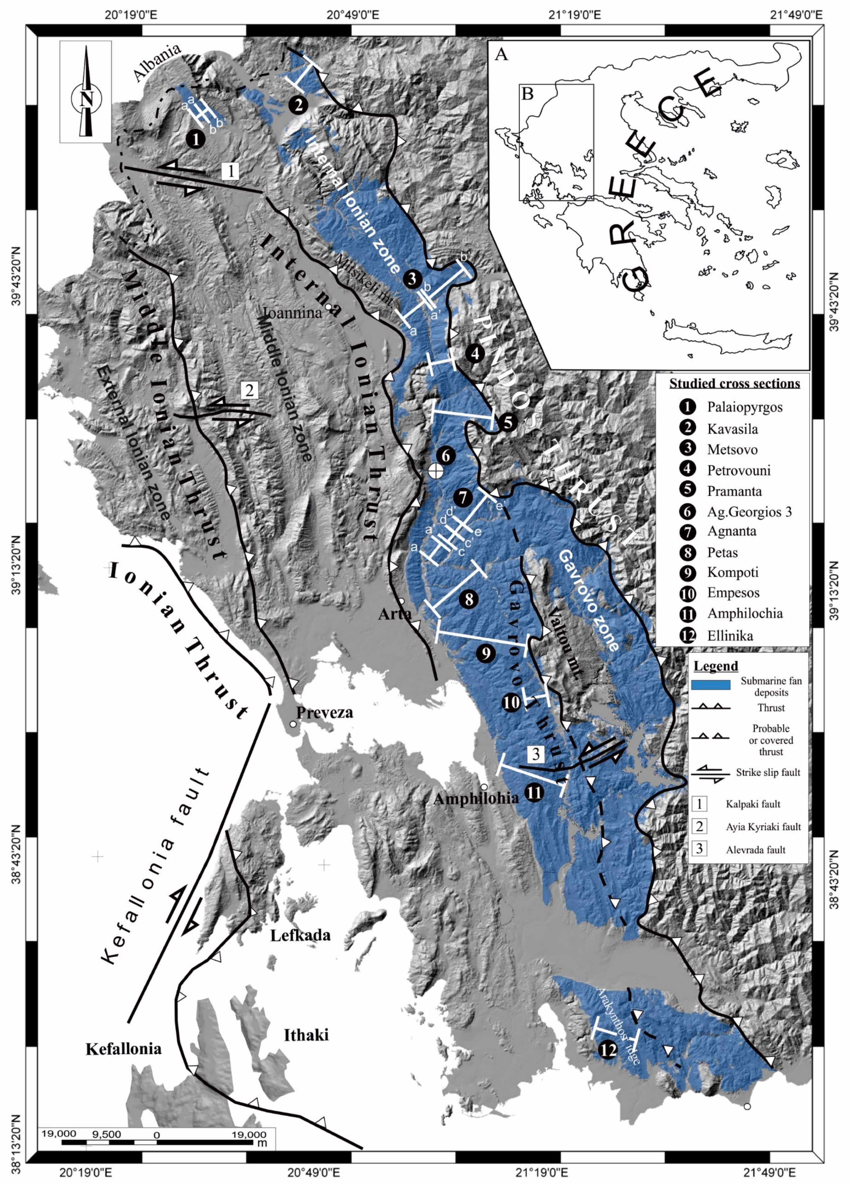
Figure 1. Internal Ionian Zone (IIZ) submarine fans extent (blue color). The major structural elements of the area are also marked, as well as the location of the measured sections.
Energies 17 00315 g001
Figure 2. Simplified chronostratigraphic correlation of available interpretations for the Ionian zone (modified from Vakalas [66] regarding the tectonostratigraphic and salt tectonics processes, suggested by various researchers [66,67,68,69,70,71]. The red rectangle corresponds to the measured stratigraphy.
Energies 17 00315 g002
Figure 3. (a) Hemipelagic mudstones (hM) overlaying Eocene limestones (bottom). (b) Very thin bedded siltstones (yellow arrows) (lS bed types). (c) Laminated mudstones. (d) Massive mudstones (mM) alternating with massive sandstones (mS). (e) Laminated mudstones. A more compacted layer probably suggests a coarser grain composition. (f) Organic material flakes oriented parallel to the lamina.
Energies 17 00315 g003
Figure 4. (a) Spaced planar-laminated sandstone corresponding to Tb3 interval after Talling [84]. (b) Massive sandstone (Ta) with planar-laminated tops (Tb2) interval in Talling [84]. (c) Massive sandstone (Ta) with rippled tops (Tc). (d) Laminated sandstones (Tb2 or Tb1) are followed by ripple cross-laminated tops. (e) Characteristic high-density turbidite with Ta interval at the base followed by laminated Tb2 interval. (f) Amalgamation surface between where subtle grain-size break occurs corresponding probably to a sandy debrite (clean sandy debrite at the base (Dcs) and discretely laminated mud (Td) at the top). (g) Mud clast (yellow arrow) floating in a medium-grained sandstone.
Energies 17 00315 g004
Figure 5. (a,b) Typical examples of cross-laminated sandstones (yellow arrows, Tc). (c,d) Well-formed convolute lamination on top of laminated sandstones. (e) Successive cross-laminated siltstones (Tc) on top of laminated fine-grained sandstones (Tb1) (the base of the succession is at the top of the photo). (f) Cross laminated sandstones (Tc).
Energies 17 00315 g005
Figure 6. (a,b) Examples of paraconglomerates alternating with sandstone and mudstone beds. (c) Well-organized, stratified, imbricated orthoconglomerate.
Energies 17 00315 g006
Figure 7. (1A) Monotonous alternations of thin- to medium-bedded sandstone with mudstones presenting an s:m ratio of 2:1 to 1:1. (1B) Alternations of thin-bedded sandstones with mudstones give an s:m ratio of 1:1 to 1:3. (2A) Thin- to medium-bedded sand-rich heterolithic facies. (2B) Sand-rich heterolytic facies characterized by an s:m ratio of >6:1. (3A) Calcareous shales overlain by bluish mudstones (CSF facies). (3B) Bluish mudstones of CSF facies passing gradually to heterolithics. (4A) Typical mud-dominated heterolithic facies. Black arrows indicate very thin sandstones corresponding to fine-grained turbidites. (4B) General view of mud-dominated heterolithic facies. Notice that the thickness of the facies is more than 60 m in the specific outcrop.
Energies 17 00315 g007
Figure 8. (1A) General view of hemipelagic mudstone facies. (1B) a pCg horizon corresponding to the DM2 interval of Talling (2012). (1C) Contorted mudstones separated by shear surfaces. (2A,B) pCg’s presenting a typical matrix-supported texture overlapped by coarse-grained sandstones. (2C) Matrix-supported pCg. (3A) Thick-bedded sandstones of MS facies. Notice the erosive basal surface of the thicker sandstone. (3B) A packet of MS facies sandstones overlaying bluish mudstones. (3C) A thickening upwards of packets of MS facies. (4A,B) Typical contorted DF facies consisting of heterolithic facies. Notice the undeformed packet overlaying the top of the DF facies. (4C) Chaotic deposits are characterized by a muddy matrix with a limestone clast floating (yellow arrow).
Energies 17 00315 g008
Figure 9. The three members of sand-matrix-supported conglomeratic facies (MCF) are (1A,C). Matrix-supported organized conglomerates of MOC facies. The deposits alternate with sandstones and mudstones, showing discrete stratification—(1B) MOC facies. The clasts are imbricated, and platy suggests reworking in a foreshore environment. (3A) Clast-supported stratified conglomerates of CsWoC facies. The specific deposits probably correspond to delta forests. (3B) General view of CsWoc facies overlapping HMF facies.
Energies 17 00315 g009
Figure 10. Biostratigraphic range of the measured sections of the Internal Ionian zone according to Vakalas [41,52]. The light reddish part of the bars indicates the uncertainty of dating due to the presence of reworked nanofossils. In the Palaiopyrgos section, a stratigraphic gap (question mark) due to a barren sample is also marked. Concerning the Pramanta section, the type of uncertainty is described in the text.
Energies 17 00315 g010
Figure 11. Stratigraphic correlation of the measured sections of the Internal Ionian Zone (IIZ) where the proposed units are also marked. The red square marks the stratigraphic extend of Agnanta E-E’ section presented in Figure 12.
Energies 17 00315 g011
Figure 12. (A) Stratigraphic correlation of Agnanta E-E’ upper part with Agnanta A-A’, C-C’, D-D’, and Petas sections. (B) Stratigraphic correlation of the northernmost measured sections (Palaiopyrgos—Kavasila sections) near the Hellenic—Albanian borders.
Energies 17 00315 g012
Figure 13. Paleocurrent directions map. Vectors are classified based on the facies associations units. Numbers in circles refer to the measured sections. The stratigraphic level of each dataset is marked in the corresponding lithostratigraphic column.
Energies 17 00315 g013
Figure 14. A schematic cross-section in an N-S orientation illustrates the five units’ proposed distribution and the various facies’ lateral correlation. The dark blue pattern indicates the calcareous Eocene basement. The Pindos thrust trace is also shown.
Energies 17 00315 g014
Figure 15. Summary maps where the evolution of the basin is shown. PT: Pindos Thrust, IIZT: Internal Ionian Zone Thrust, GT: Gavrovo Thrust, KTZ: Kastaniotikos Transfer Zone, ATZ: Alevrada Transfer zone.
Energies 17 00315 g015
Table 2. Summary of the applied facies scheme.
FaciesDescriptionLithological Types
Calcareous shaly facies (CSF)Fine-grained, light-bluish to grayish marly mudstones consisting mainly of hemipelagic mudstones (hM) interbedded with massive mudstones (mM). Planar-laminated (plS) and cross-laminated sandstones (clS) are typical. Thickness up to 30 mhM, mM, plS, clS
Mud-Dominated Heterolithic facies (MHF)Alternations of bluish to grayish massive mudstones (mM) with very thin to thin-bedded (up to 2–3 cm) siltstones or very fine-grained sandstones. Thickness up to 100 mmM, plS, clS, hM
Heterolithic facies (HF)Heterolithic facies consist of sandstones (mainly laminated sandstones (lS) and, to a lesser degree, massive sandstones (mS) that are interbedded with massive (mM) and laminated mudstones (lM) and to a lesser degree by hemipelagic mudstones (hM). Thickness up to 200 mplS, clS, mS, mM, lM, hM
Sand-Dominated Heterolithic facies (SHF)Sand-dominated heterolithic facies consist of all the lithological types of sandstones (mS, lS), various sandstones (types) interbedded with massive (mM) or laminated (lM) mudstones. Thickness up to 200 m.mS, lS, mM, lM
Massive sandstone beds facies (MS)Massive sandstone bed facies consist of packets 50 to 100 m thick formed mainly by massive sandstone beds (mS) 10–100 cm thick. Rarely, at the top of the beds, planar-laminated sandstones occur (plS) in stratification. Pebbly sandstone lags may be present (oCg lithofacies).mS, plS, oCg
Deformed facies (DF)Deformed facies consist of blocks of contorted, folded, deformed sandstone and mudstone facies of various lithological types (mS, lS, mM), with evidence of brecciation. Thickness up to 30 m.mS, lS, mM
Hemipelagic mudstone facies (HMF)Structureless, bluish to grayish mudstones consisting mainly of massive mudstone lithofacies (mM). Intervals of very thin to thinly bedded siltstones (up to 5 cm) may occur, characterized by rippled top beds (clS lithofacies)mM, clS
Matrix-supported pebbly mudstone facies (PMF)PMF facies consist almost exclusively of mud-matrix-supported pebbly to cobbled mudstones (pCg lithofacies), forming intervals that range in thickness from 4–20 m.pCg
Matrix-supported organized conglomerates facies (MOC)Sand-matrix clast-supported organized conglomerate facies are composed mainly of alternations of pCg lithological types (granular to pebbly concerning class size) with coarse-grained massive sandstone beds (mS) that at the top gradually pass to planar-laminated sandstones (plS). Thickness up to 10 mpCg, mS, plS
Poorly organized clast-supported conglomerates (CsPoC)Sand-matrix clast-supported poorly sorted conglomerates of (pCg) lithological type with extremely erosive bases, poor lateral extent, and a maximum thickness of 80 m. At the base of the conglomerates, massive mudstone fragments (mM) showing a size of 1.5 × 2.0 m are present.pCg, mM
Well-organized clast-supported conglomerates (CsWoC)Well-organized sand-matrix clast-supported conglomerates are characterized by inclined bedding planes consisting mainly of oCg lithological type. Massive sandstone beds (mS) 15 cm thick are also present at the top of the facies. Thickness up to 50 m.oCg, mS
Table 3. Summary of the biostratigraphic anal or very fine-grained sandstysis presented by Vakalas [41] & Vakalas et al. [52] SL: Stratigraphic level; NP: Calcareous nannofossil zone. Question mark (?) represents uncertainties on the determined age.
KavasilaPalaioPyrgosMetsovo AA Metsovo BBPetrovouni
SLNPSLNPSLNPSLNPSLNP
74020–2127020220018–22187524–25180020–23
61020–2119020–21185017–20165024–25175020–23
24020–21130-145017–201350-170020–23
17020–213016110016110022–23165020–23
3020–21 40013–1670021–23110020–22
020–21 7513–1640021–2298020–22
8521–22730-
68020–23
38020–22
3019–20
018–20
PramantaAgnantaPetasKompotiAmphilochiaEllinika
SLNPSLNPSLNPSLNPSLNPSLNP
398019–20318021–23180021–22 ?100024–25 ?315023–24180024–25
329019–20314021–23151021–2490024–25 ?260023–24162024–25
322019–20312021–23120021–24720-1450-140021–23
315019–20307021–23100021–2268024–25140021–23109021–23
257018–20270021–2360021–2342024–251290-108021–23
190018–20265021–2333021–2240024–251270-69021
160018–20260021–2225021–2238024–251200-380-
128018240021–2302115024–25115021–2221017–20
106018218021–23 10024–2598021–222017–20
93017138021–23 85021–22
770-127021–23 80021
480171150- 76021
3017106021–23 730-
01687021–23 68021–22
81021–23 62021–22
78021–23 55021–22
70021–23 47021–22
68021–23 42021–22
63021–23 41021
57021–22 32021
50021–22 220-
20021
170-
15021
Disclaimer/Publisher’s Note: The statements, opinions and data contained in all publications are solely those of the individual author(s) and contributor(s) and not of MDPI and/or the editor(s). MDPI and/or the editor(s) disclaim responsibility for any injury to people or property resulting from any ideas, methods, instructions or products referred to in the content.