Abstract
Phase change energy storage technology enhances the integration of renewable resources into low-carbon energy systems for grassland pastoral settlements, further addressing the balance between energy needs and environmental sustainability. This study examines a heating system using an experimental platform in an environmental chamber, where the thermal storage and release processes of phase change energy storage flooring were monitored. The results revealed that phase change energy storage flooring exhibits higher heat transfer efficiency and faster heating rates. Under 40 °C heating conditions, the heating rate of the thermal storage layer increased by 12.5% within 1 h. The flooring also demonstrated superior heat release performance, with the peak heat flux of the thermal storage layer delayed by 15 min. Higher heating temperatures shortened the heating time and extended the heat release duration of the phase change energy storage flooring. Under 45 °C heating conditions, the heat transfer efficiency of the surface temperature of the thermal storage layer increased by 38% within 1 hour and by 24.7% over 4 h. In addition, energy consumption in different tests was analyzed, and thermal conductivity was discussed according to the heat transfer model. Phase change energy storage flooring, when coupled with the abundant solar energy resources available in grassland pastoral areas, presents a viable option for the construction of low-carbon energy systems in grassland pastoral settlements.
1. Introduction
Human activities have always been closely connected to their environment. The Inner Mongolian grasslands, one of China’s largest grasslands and natural pastures, are located on the Inner Mongolian Plateau. Most of this region lies within areas rich or relatively rich in solar energy resources. According to the “Inner Mongolia Renewable Energy Development Report 2023”, the theoretical solar power potential in the Inner Mongolia Autonomous Region is estimated to be 94 billion kW, accounting for approximately 21% of the national total, indicating significant potential for solar energy utilization [1].
The climate of the Inner Mongolia Autonomous Region is classified as severely cold, with year-round cold temperatures and long winter heating periods. In 2022, the average rural household in the pastoral areas of the Inner Mongolia Autonomous Region consumed 1233 kg of loose coal per capita, significantly higher than the 724 kg average in neighboring provinces [2]. The high construction and maintenance costs required for centralized heating systems in grassland pastoral settlements make it essential to integrate renewable energy sources, especially in decentralized systems [3,4,5].
The abundant solar energy resources in grassland pastoral areas provide favorable conditions for renewable energy-based heating solutions. Considering the unique climate and lifestyle characteristics of grassland pastoral areas, the research team proposed the application of a solar water-based concrete thermal storage flooring system to improve the indoor thermal environment of grassland pastoral settlements [6]. This system includes a solar collector system, an auxiliary heating system, and a radiant floor system.
The use of a solar water-based concrete thermal storage flooring system can significantly reduce the consumption of commercial energy. With the continuous promotion of clean heating in northern China over the past few years, the energy consumption structure in rural areas has undergone significant changes. In 2022, the total energy consumption in the rural pastoral areas of the Inner Mongolia Autonomous Region was equivalent to 9.83 million tons of standard coal, with commercial energy accounting for over 90% of this total [2]. However, the application of solar water heating systems faces challenges, such as instability and complex maintenance [6].
Enhancing the thermal storage capacity of building envelopes and effectively utilizing renewable energy sources, such as solar energy, are key strategies for addressing the current energy consumption issues in grassland pastoral settlements. Integrating existing energy collection technologies with building structures is essential for improving energy efficiency. The use of thermal storage technologies within buildings can address the cyclical instability associated with solar and wind energy utilization [7,8]. Moreover, it can significantly improve the indoor thermal environment, making it a crucial approach to enhancing the energy efficiency of buildings in grassland pastoral areas and optimizing their energy consumption structure.
Advanced material technologies have demonstrated that high-energy-density phase change materials (PCMs) can provide substantial thermal storage within a narrow temperature range [9,10,11,12]. By increasing the thermal inertia of building materials and offering favorable thermal regulation effects, these materials can smooth out fluctuations in energy demand to some extent [13,14]. Mohamed Lachheb et al. [15] reviewed the impact of specific factors, such as the type, location, and number of PCMs, on improving building energy efficiency and indoor thermal comfort and showed that the use of PCMs in brick walls is a promising technology that can reduce indoor temperature fluctuations and save energy. Bence Nemeth et al. [16] conducted a study on the thermal performance and electricity demand of two container model houses and found that PCMs plasters can reduce electricity demand by 10.3% and 7.0%, respectively, over the entire winter compared to reference houses using electric radiators or heat pumps. Yuan Zhang et al. [17] designed a building with Trombe walls and PCMs, and the indoor discomfort degree-hour (IDH) and integrated indoor discomfort duration (ID) were analyzed. The results showed that ventilation in Trombe walls using PCMs is the most effective way to reduce IDH. In order to reduce the mismatch between indoor daytime and nighttime temperatures in Pakistani homes during winter, Aurang Zaib et al. [18] investigated a heat exchanger using phase change materials coupled with solar energy, and the results showed that the device could minimize the household heat load while maintaining indoor thermal comfort. Using Energy plus software, Asasei Unarine Casey Ndanduleni et al. [19] simulated temperature fluctuations on residential roofs in South Africa and showed that a 30 mm thick PCMs layer could significantly reduce indoor temperature fluctuations by reducing the temperature to between 14 and 16 °C. Oumayma Babaharra et al. [20] conducted a numerical evaluation of a heated floor with PCMs, showing that the best thermal performance improvement can be achieved by placing PCMs above the heating tubes. Ibtissam Afaynou et al. [21] studied the influence of composite PCMs type, porosity, and other parameters on the thermal properties of the material. The results show that PCMs composites with high porosity have higher heat transfer rates and more uniform melting processes. This contributes to improving overall energy utilization efficiency and reducing reliance on fossil fuels.
Incorporating PCMs into cement mortar results in thermal storage materials with excellent thermal performance, which can be further applied in the construction of solar water-based phase change energy storage flooring [7,22,23,24]. As shown in Figure 1, slag cement mortar combined with microencapsulated phase change materials (mPCM) is used as the thermal storage layer in the radiant floor system. This advanced energy storage technology addresses the cyclical variations of renewable resources in grassland pastoral areas and aligns with existing peak–valley electricity pricing policies [8], thereby balancing the energy needs of grassland pastoral dwellings with environmental considerations.
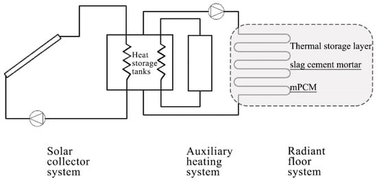
Figure 1.
Solar water-based phase change energy storage flooring.
The abundant renewable resources in the Inner Mongolian Plateau offer significant potential for developing low-carbon energy systems in grassland pastoral settlements, examining the heating system using an experimental platform in an environmental chamber, where the thermal storage and release processes of phase change energy storage flooring were monitored. The energy consumption in different tests is analyzed, and the thermal conductivity is discussed according to the heat transfer model. The emphasis is on optimizing the heating terminal while also considering future scenarios where it could be integrated with the supply side of renewable energy sources. This approach holds substantial potential for the development and utilization of renewable energy, contributing to the creation of comfortable thermal environments in grassland pastoral dwellings and advancing green energy-efficient development.
2. Materials and Methods
A field survey was first conducted in a grassland pastoral area in central Inner Mongolia to determine the indoor temperature conditions during winter, both with and without heating, and to understand the actual heating behavior patterns. Figure 2 shows an aerial photograph of a typical grassland pastoral settlement.
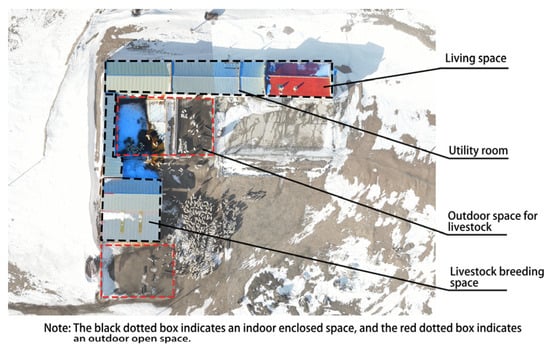
Figure 2.
Aerial photograph of a typical grassland pastoral settlement.
The field survey was conducted from 17 February to 24 February 2024. During this period, a temperature data logger (RC-4HC, Jingchuang Electric Co., Ltd., Jiangsu, China) was used to monitor the temperatures both indoors and outdoors at a height of 1.5 m. As shown in Figure 3, the average outdoor temperature at the grassland dwelling was −6 °C, with the lowest nighttime temperature reaching −17 °C. The average daily temperature in the heated room was 15 °C; in contrast, the average daily temperature in the unheated room was 3 °C, with the lowest nighttime temperature dropping to −3 °C.
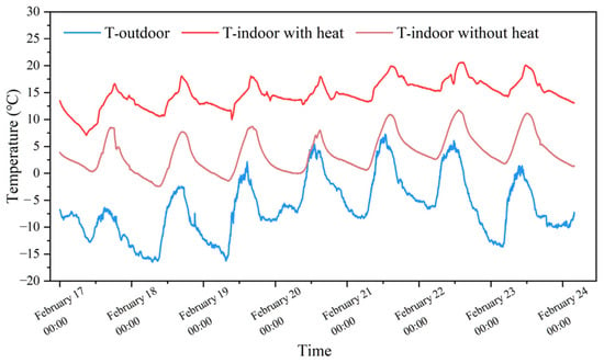
Figure 3.
Indoor and outdoor temperatures of grassland dwellings in winter.
The heated room in this building utilizes a decentralized electric heating water tank and radiant flooring as the heating system. Typically, users activate the heating equipment between 16:00 and 20:00. It is important to note that this region implements a peak–valley electricity pricing policy, with a low valley rate of 0.165 CNY/kWh from 18:00 to next day 08:00, and a high peak rate of 0.465 CNY/kWh from 08:00 to 18:00. Additionally, the heat source input is unstable. Advanced thermal storage materials hold promise for leveraging renewable energy to address heating energy consumption during non-valley hours and potentially extending heating duration.
2.1. Fabrication of the Radiant Floor Module
The phase change energy storage flooring was fabricated by incorporating mPCM (Thermalcare 32, Shanghai Xinya New Materials Technology Co., Ltd., Shanghai, China) into the thermal storage layer shown in Figure 1. This PCM consists of paraffin encapsulated in a polymer resin shell, which transitions between solid and liquid phases. The base thermal storage layer utilized slag cement (PSA32.5, Zhucheng 97 Building Materials Co., Ltd., Shandong, China) with good thermal performance [25], standard sand (ISO middle grade, Xiamen ISO Standard Sand Co., Ltd., Fujian, China), and water. Table 1 shows the material quantities used.

Table 1.
The material quantities used of the thermal storage layer of the radiant floor module.
The phase change energy storage flooring was fabricated by replacing an equal mass of fine aggregate with mPCM [11,26]. The mPCM were introduced early in the raw material mixing process [27], following these steps: (1) The slag cement and sand were weighed according to the specified proportions and mixed evenly to form a dry mix; (2) tap water was then weighed according to the specified proportions and added to the dry mix; and (3) the mortar was mixed at low speed for 60 s to form the mortar mixture.
As shown in Figure 4, the casting of the phase change energy storage flooring involved assembling all pre-prepared materials and using a manual pressurization device to inject water and apply pressure to the module. Four sets of K-type thermocouples were pre-embedded in the thermal storage layer, with each set containing seven thermocouples that recorded temperature changes at different depths within the thermal storage layer.
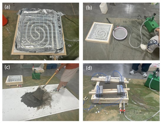
Figure 4.
Field installation of radiant floor module: (a) radiant floor module production; (b) manual water injection and pressure; (c) thermal storage mortar preparation; and (d) fixation and maintenance.
The construction and casting of the different radiant floor modules were completed within two hours for each module. Afterward, they were placed in a laboratory for natural curing, with water sprayed twice daily. The curing period for the thermal storage layer exceeded 30 days. Before testing, four heat flux sensors were attached near the temperature measurement points using thermal grease.
2.2. Testing Method for the Radiant Floor Module
The use of PCMs in flooring requires consideration of many influencing factors, including the content of phase change materials, heating temperature, and other conditions. In this study, the heat storage and release process of the floor using phase change materials is tested by controlling a single variable in a controlled thermal environment. Secondly, the heating process of grassland pastoral areas also faces the problem of unstable heat sources; in this study, adjustable heat sources are used to achieve different input heating temperatures. To evaluate the thermal performance of the phase change energy storage flooring during heating, cooling, and under different water supply temperatures, an artificial environmental chamber was used as a testing environment that closely simulates the ideal thermal conditions of a grassland pastoral settlement. The environment chamber can adjust the ambient temperature between −30 °C and 30 °C according to the requirements. According to the actual measurement shown in Figure 3, the indoor thermal environment of the residence in the grassland pastoral area can be replicated under the condition of no heating. As shown in Figure 5a, the experimental system primarily consists of a controlled electric heating water tank, a circulation pump, supply and return pipelines, the radiant floor module, a cooling air unit, and a testing system. The arrangement of the temperature measuring points and heat flow measuring points of the phase change energy storage floor is shown in Figure 5b. In the study, the phase change temperature of the thermal management material is 32 °C; thus, the thermocouple is used to monitor the temperature change during the heating and cooling process of the phase change energy storage floor. In addition, a heat flux meter is used to detect the heat release of the phase change energy storage floor.
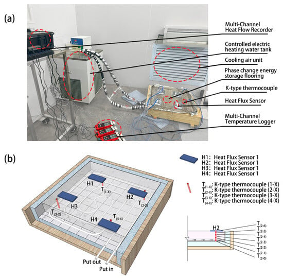
Figure 5.
The test system of phase change energy storage flooring: (a) components of the test system; (b) placement of sensors in the floor.
The controlled electric heating water tank is equipped with an electric heater, allowing for precise adjustment of the water supply temperature. This feature enables the differential adjustment of the heat input to the radiant floor module, simulating the variable heating conditions typical of grassland pastoral dwellings. The parameters of the testing instruments and equipment are listed in Table 2.

Table 2.
Test equipment and parameters.
As shown in Table 3, to test the thermal performance of the radiant floor module during heating, cooling, and under different water supply temperatures, the experiment was divided into four distinct tests. According to the results of the preliminary field investigation, the water temperature of the electric heating water tank used in the grassland pastoral area is generally 40 °C in the operation stage; in the heating phase of this experiment, a controlled electric heating water tank was used to supply hot water, with the supply temperatures set to 35 °C, 40 °C, and 45 °C. During the cooling phase, the cooling air unit of the artificial environmental chamber was used to lower the temperature, with the cooling unit set to 0 °C.

Table 3.
Experimental working condition settings.
3. Results and Analysis
3.1. Thermal Storage Characteristics of the Radiant Floor
Figure 6 shows the changes in the temperature and surface heat flux across the thermal storage layer of the radiant floor module during the heating phase in Tests 1 and 3. Figure 6a presents the results for the radiant floor module without added mPCM. As shown in the figure, the temperature trends at various measurement points in the thermal storage layer during the heating phase are generally consistent: within the first hour, due to the temperature difference between the heat source and the thermal storage layer, the average temperature of the thermal storage layer increased from 15 °C to 27 °C, with the corresponding surface heat flux rapidly increasing from 5 W/m2 to 20 W/m2.
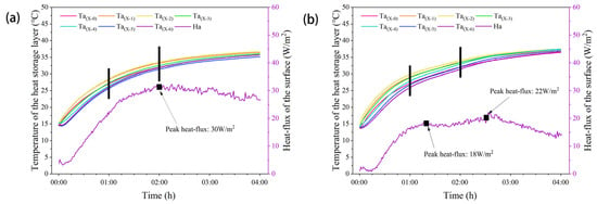
Figure 6.
Average temperature and surface heat flux of the thermal storage layer during the heating process: (a) Test 1; (b) Test 3. The short black line divides the experimental phase.
During the 1 to 2 h heating period, the rate of the temperature increases in the thermal storage layer slowed, with the average temperature rising from 27 °C to 32.5 °C, and the highest temperature reaching 33.6 °C. The corresponding surface heat flux’s rate of increase also slowed, peaking at 30 W/m2 at the 2 h mark. After 2 h of heating, as the temperature difference between the heat source and the thermal storage layer further narrowed, the rate of temperature increases in the thermal storage layer further decreased. The average temperature rose from 32.5 °C to 36 °C, and the temperature variation curves at each measurement point began to level off. During this phase, the surface heat flux of the thermal storage layer remained steady at 27 W/m2.
Figure 6a also illustrates the temperature differences across various locations within the thermal storage layer. The heat source in the radiant floor module is concentrated about 1~2 cm from the aluminum foil reflective layer, with only the upper surface able to transfer heat to the air. The highest temperature distribution within the thermal storage layer is centered around positions (X-2) and (X-1), gradually decreasing outward. The temperature distribution throughout the heating phase aligns with theoretical expectations and conforms to the basic principles of steady-state heat transfer.
Figure 6b presents the test results for the radiant floor module with added mPCM. As shown in the figure, the temperature increases at various measurement points in the thermal storage layer during the initial heating stage vary significantly, but they become more consistent over time. During the first hour, due to the temperature difference between the heat source and the thermal storage layer, the average temperature of the thermal storage layer increased from 14.5 °C to 28 °C, with the corresponding surface heat flux rapidly increasing from 5 W/m2 to 17 W/m2.
In the 1 to 2 h heating period, the rate of temperature increases in the thermal storage layer slowed, with the average temperature rising slowly from 28 °C to 31.7 °C at the 1 h 45 min mark, then gradually to 32.7 °C. The corresponding surface heat flux exhibited a first peak and a trough at 17 W/m2 at the 1 h 45 min mark. After 2 h of heating, the rate of temperature increases in the thermal storage layer slightly accelerated until 2 h 30 min, after which it slowed down again due to the further narrowing of the temperature difference between the heat source and the thermal storage layer. During this phase, the average temperature rose from 32.7 °C to 37 °C, with the surface heat flux peaking at 22 W/m2 at 2 h 30 min before decreasing.
Figure 6b also shows the temperature differences at various locations within the thermal storage layer: During the initial heating period, there were significant temperature differences within the thermal storage layer, with positions (X-1) and (X-2), which are closer to the heat source, consistently having the highest temperatures. In contrast, positions (X-5) and (X-6), which are closer to the upper surface, had the lowest temperatures within the first 2 h of heating—a phenomenon that persisted until after 2 h. Additionally, it is noteworthy that positions (X-5) and (X-6) near the upper surface of the radiant floor did not exhibit a reduction in the temperature increase rate due to phase change thermal storage.
From the perspective of surface heat flux in the thermal storage layer, the average heat flux throughout the heating process in Figure 6b was 15.1 W/m2, lower than the 24.6 W/m2 observed in Figure 6a. This difference is attributed to the lower thermophysical properties of mPCM, including lower thermal conductivity and thermal diffusivity, as previously demonstrated by earlier studies [7]. Notably, unlike the conventional thermal storage floor, the phase change thermal storage floor exhibited two peak heat fluxes during the heating process. The changes in average surface heat flux reflect the variation in heat transfer from the heat source. The slight decrease in average heat flux between 1 h 15 min and 2 h 30 min corresponds to the phase change thermal storage process, during which the rate of temperature increases in the thermal storage layer slowed.
3.2. Thermal Release Characteristics of the Radiant Floor
Figure 7 shows the changes in temperature and surface heat flux across the thermal storage layer of the radiant floor module during the cooling phase in Tests 1 and 3. Figure 7a presents the results for the radiant floor module without added mPCM. As shown in the figure, the temperature decline trends at various measurement points in the thermal storage layer during the cooling phase are generally consistent: during the first 30 min, the heat source continued to supply heat, causing the temperature of the thermal storage layer to rise further. The highest temperature at (X-1) increased to around 38 °C, while (X-6), due to direct heat exchange with the air, remained around 35.5 °C. After this period, the thermal storage layer maintained a relatively low cooling rate, with the corresponding surface heat flux rapidly increasing and reaching a peak of 186.3 W/m2 at the 1 h mark.
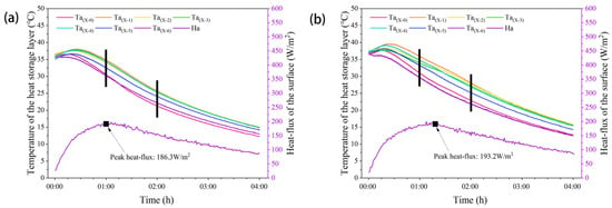
Figure 7.
Average temperature and surface heat flux of the thermal storage layer during the cooling process: (a) Test 1; (b) Test 3. The short black line divides the experimental phase.
During the 1 to 2 h cooling period, the cooling rate of the thermal storage layer increased, with the average temperature of the thermal storage layer decreasing from 32.9 °C to 25.6 °C. From the 2 h mark until the end of the experiment, the temperature difference between the thermal storage layer and the environment diminished, leading to a further reduction in the cooling rate, with the highest temperature dropping from 25.6 °C to 15 °C. Correspondingly, the surface heat flux after the 2 h mark showed a steady decline.
Figure 7a also illustrates the temperature differences at various locations within the thermal storage layer: During the initial cooling stage, the heat source in the radiant floor module is concentrated about 1–2 cm from the aluminum foil reflective layer, with the highest temperature distribution centered around positions (X-1) and (X-2), gradually decreasing outward. The cooling process began first at (X-6), which was closest to the cooling load. It is noteworthy that (X-0) had the lowest temperature at the 1 h cooling mark, and this remained the case until the end of the experiment. After 1 h of cooling, the temperature field distribution within the thermal storage layer stabilized, with the highest temperatures centered around positions (X-2) and (X-3), gradually decreasing outward.
Figure 7b presents the test results for the radiant floor module with added mPCM. As shown in the figure, during the initial cooling stage, the temperature variations at various measurement points in the thermal storage layer differed significantly. During the first 30 min, the heat source continued to supply heat, causing the average temperature of the thermal storage layer to continue rising, with the highest temperature at (X-1) reaching 39.5 °C. Subsequently, due to the high temperature within the thermal storage layer, it maintained a relatively fast cooling rate, with the corresponding surface heat flux rapidly increasing.
During the 1 to 2 h cooling period, the cooling rate of the thermal storage layer decreased, with the average temperature dropping from 33.3 °C to 28.1 °C, and the highest temperature at 1 h 15 min decreasing to 33.2 °C. The corresponding surface heat flux reached a peak of 193.2 W/m2, after which the cooling rate within the thermal storage layer increased slightly. From the 2 h mark until the end of the experiment, the cooling rate of the thermal storage layer began to decrease again.
Figure 7b also shows the temperature differences at various locations within the thermal storage layer: During the initial cooling stage, the highest temperature distribution within the thermal storage layer was centered around positions (X-1) and (X-2), gradually decreasing outward, with the surface of the thermal storage layer at (X-6) cooling first. During the 1 to 2 h cooling period, the temperature differences within the thermal storage layer were more pronounced, with the highest temperatures centered around positions (X-2) and (X-3), gradually decreasing outward.
From the perspective of surface heat flux in the thermal storage layer, the average heat flux throughout the cooling process in Figure 7b was 139.0 W/m2, slightly higher than the 137.6 W/m2 observed in Figure 7a. This increase is attributed to the higher thermophysical properties of the mPCM after melting, as demonstrated by previous studies [7]. Notably, compared to the conventional thermal storage floor, the phase change thermal storage floor reached a peak surface heat flux of 193.2 W/m2 at 1 h 15 min during the cooling process, with the peak heat release flux delayed by 15 min.
3.3. Impact of Heating Temperature on Thermal Performance
Figure 8 shows the changes in surface temperature and surface heat flux of the thermal storage layer during Tests 2, 3, and 4.
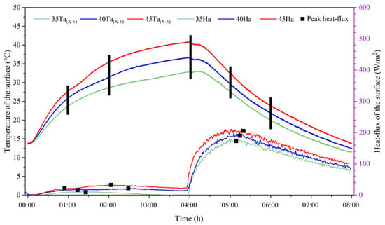
Figure 8.
Average surface temperature and surface heat flux under different water supply temperatures. The short black line divides the experimental phase.
As shown in the figure, the surface temperature of the thermal storage layer under different water supply temperatures follows the same trend: Within the first hour of heating, the surface temperature of the thermal storage layer increases rapidly. The rate of temperature rise in Test 4 is greater than in Test 3, which is greater than in Test 2, with temperature increases of 13.8 °C, 12 °C, and 10 °C, respectively. During this stage, sensible heat storage dominates, and the higher the heat source input temperature, the faster the rate of temperature increase. Compared to Test 2, Test 4 with a higher heat source improved the heat transfer efficiency by 38%.
During the 1 to 2 h heating period, the rate of temperature increase in the thermal storage layer decreases in all tests, indicating that the latent heat storage phase requires the absorption and storage of more heat. In Test 4, the phase change heat storage time is shorter, with a noticeable increase in the rate of temperature rise at around 1 h 20 min. In Test 3, the surface temperature starts to increase steadily at 1 h 30 min, while the temperature change in Test 2 during this stage is more gradual. Compared with Test 2, Test 4, with a higher heat source, reduces the time of phase transition by 50%.
After 2 h of heating, the rate of temperature increase in the thermal storage layer surface further decreases. It is noteworthy that in Test 2, the rate of temperature increase remains constant during this phase. At the end of heating, the average surface temperature of the thermal storage layer in Test 4 is 40.9 °C; in Test 3, it is 36.7 °C; and in Test 2, it is 32.8 °C. Compared with Test 2, the heat transfer efficiency of Test 4 with a higher heat source was improved by 24.7%. During the cooling phase, the average surface temperature of the thermal storage layer decreases similarly across all tests. However, due to the higher heat source input in Test 4, more heat is retained, resulting in the highest average surface temperature of approximately 13.8 °C at the end of the cooling phase.
From the perspective of surface heat flux in the thermal storage layer, different water supply temperatures alter the timing of peak heat flux in the phase change thermal storage radiant floor. During the heating phase, the two peak heat fluxes in Test 4 occurred at 50 min and 2 h 5 min; in Test 3, at 1 h 17 min and 2 h 30 min; while in Test 2, only one peak heat flux was observed at around 1 h 27 min. During the cooling phase, the peak heat flux times were 1 h 20 min for Test 4, 1 h 15 min for Test 3, and 1 h 10 min for Test 2.
4. Discussion
This study employs phase change thermal storage technology to enhance the thermal performance of radiant floors. An experimental platform was established in an environmental chamber based on the energy usage patterns of grassland pastoral dwellings. As the first step in constructing the thermal environment of grassland pastoral dwellings, this approach holds significant importance for improving building energy efficiency, optimizing energy consumption structures, and balancing the relationship between energy demand and the environment.
For the heating phase, the low physical properties of mPCM do not impact the final state of the thermal storage floor. Comparing Figure 6a,b, it can be observed that under the same heat source conditions, the addition of mPCM to the radiant floor module alters its heat transfer characteristics: Within the first hour of heating, the phase change energy storage flooring exhibits higher overall heat transfer efficiency and a faster rate of temperature increase, with the rate of temperature rise in the thermal storage layer increasing by 12.5%. During the 1 to 2 h heating period, phase change thermal storage causes the rate of temperature increase in the thermal storage layer to slow down, with the temperature rise decreasing by 14.5%, but the overall average temperature of the thermal storage layer at 2 h increased by 0.2 °C. After 2 h of heating, the phase change energy storage flooring experiences a growth in the rate of temperature increase, with the temperature slowly rising after 2 h 30 min, ultimately leading to an overall average temperature increase of 1 °C. The faster rate of temperature increase helps eliminate the initial uneven temperature distribution in the phase change energy storage flooring and results in a higher final average temperature in the thermal storage layer, which is beneficial for the heat release of the phase change energy storage flooring.
For the cooling phase, the high-energy-density mPCM improves the heat release performance of the thermal storage floor. Comparing Figure 7a,b, it is evident that under the same cooling source conditions, the addition of mPCM in the radiant floor module alters its heat transfer characteristics: The temperature change curves show that during the first hour of the initial cooling phase, the phase change energy storage flooring continues to rise in temperature, with the average temperature of the thermal storage layer increasing by 0.8 °C. During the 1 to 2 h cooling period, the phase change heat release causes the rate of temperature decrease in the thermal storage layer to slow down by 28.8%, delaying the peak heat flux by 15 min, and the overall average temperature of the thermal storage layer at 2 h increased by 2.5 °C. After 2 h of cooling, the cooling rate of the phase change energy storage flooring gradually decreases, with the temperature slowly declining after 2 h 30 min, ultimately leading to an overall average temperature increase of 0.4 °C. The delay in peak heat flux allows the phase change thermal storage floor to maintain a higher temperature and extend the heat release duration.
The power consumption of the controlled electric heating water tank during different tests is shown in Table 4; by comparing Test 1 and Test 4, phase change energy storage flooring can improve the energy efficiency of conventional flooring by 1.7%. A further analysis of the results shown in Figure 8 reveals that a higher-temperature heat source increases the energy consumption of the radiant floor module. The additional energy results in more efficient heat transfer, a faster rate of surface temperature increase, a higher surface temperature at the end of the heating period, and a longer heat release duration. This is particularly suitable for the utilization of solar energy, further coupling renewable resources with the decentralized energy systems of grassland pastoral dwellings.

Table 4.
The material quantities used of the thermal storage layer of the radiant floor module.
The optimal result in this experiment was obtained in Test 4. According to the results shown in Figure 6a and Figure 8, the final surface temperature of the floor in Test 1 after 4 h of heating was 35.7 °C, whereas in Test 4, this temperature was reached in just 2 h of heating. Based on the results shown in Figure 6b and Figure 8, after 2 h of heating, the phase change energy storage flooring had fully undergone the phase change process, with a uniform internal temperature distribution under sensible heat storage. Figure 8 also shows that during the cooling phase, the surface temperature of the floor in Test 4 took approximately 20 min longer to drop to the initial temperature compared to Test 1.
At present, the use of phase change materials in building envelope requires a lot of experimental research in the early stage, and the related research also shows that it has achieved good performance in energy efficiency. In the grassland pastoral area, the winter heating period lasts up to 6 months each year. Currently, grassland pastoral dwellings use decentralized electric heating water tanks for heating between 16:00 and 20:00 daily. If a solar water-based phase change energy storage flooring were used, heating could be provided by solar collector system from 16:00 to 18:00, with an electric auxiliary heating system from 18:00 to 20:00. This system could reduce annual heating costs by 50% per square meter of phase change energy storage floor.
Figure 9 illustrates the variations in temperature across different locations within the thermal storage layer and the surface heat flux during the cooling phase of Test 4. The surface temperature of the flooring decreases to the initial level after 3 h and 56 min of cooling. Due to the low thermal conductivity of the mPCM, the internal temperature of the flooring in Test 4 remains higher, with an average temperature of 16.5 °C. In contrast, in Test 1, as shown in Figure 7a, the surface temperature of the flooring returns to the initial level after 3 h and 32 min of cooling, with an average temperature of only 15.7 °C. Furthermore, at the end of the cooling period, the surface heat flux of Test 4 remains at approximately 100 W/m2, whereas, for the same cooling duration, the surface heat flux of Test 1 is only 85 W/m2. The higher internal temperature of the flooring in Test 4 enables a longer heat release duration.
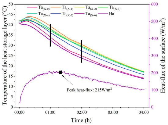
Figure 9.
Average temperature of the heat storage layer and surface heat-flux during the cooling process. The short black line divides the experimental phase.
As shown in Figure 5, a large number of thermocouples and heat flow sensors were set up in the phase change energy storage floor in this experiment to form a simple heat conduction test device. For example, Behnam Mobaraki et al. [28,29] used the temperature-based method (TBM) and the heat flux meter (HFM) method to discuss the influence of sensor position on the measurement accuracy of U value. According to Fourier’s law (law of heat conduction) formula, the heat flux is proportional to the temperature difference between the two sides of the material, the thermal conductivity of the material, and the thickness of the material is inversely proportional. We extracted the data of surface temperature, bottom temperature and surface heat flux of the phase change storage floor in the experiment and calculated the thermal conductivity of the steady-state heat transfer part.
where is the thermal conductivity of the material (W m−1 K−1), is the heat flux through the material (W), is the thickness of the material (m), and is the temperature difference between the two sides of the material (K).
Thermal conductivity reflects the ability of the material to transfer heat. In this experiment, the temperature field is centered on the heat pipe, and the heat can only be transferred towards the upper surface of the phase change energy storage floor. Therefore, Ta(X-2) and Ta(X-6) are selected as reference temperatures, and the thermal conductivity of Test 1 and Test 3 is calculated. As shown in Figure 10, PCMs can significantly reduce the thermal conductivity of the floor. Test 1: In the dynamic heating process, the thermal conductivity is proportional to the heating time, and it increases with the increase in the floor temperature. However, in Test 3, two stages of growth occurred during the dynamic heating process. Figure 6 shows that in Test 3, the temperature rise rate slowed down between 1 and 2 h, and the surface heat flow remained stable, corresponding to the thermal conductivity shown in Figure 10, which remained unchanged at this stage.
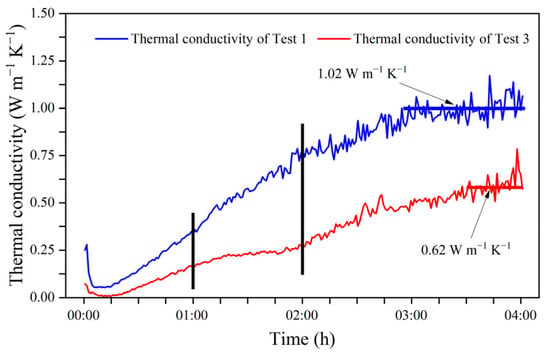
Figure 10.
Thermal conductivity calculated according to Fourier’s law. The short black line divides the experimental phase.
According to the results shown in Figure 6, the stage with reference temperature difference less than 1 °C is selected as the steady-state heat transfer model. For Test 1, its thermal conductivity is 1.02 W m−1 K−1, while that for Test 3 is 0.62 W m−1 K−1.
It is important to note that, as shown in Figure 3, the indoor temperature gradient during the night in a grassland pastoral dwelling without heating is relatively small. In this experiment, forced mechanical ventilation was used for cooling in all tests, with indoor temperatures dropping to 0 °C within 1 h, which ultimately delayed the heat release time by approximately 20 min. In the dynamic load environment of an actual grassland pastoral dwelling, the heat release time of the phase change energy storage flooring would be further delayed. Secondly, the cost of phase change energy storage floor is also the difficulty of using PCMs in the current building envelope structure. As shown in Figure 8, the higher heating temperature can improve the thermal performance of the phase change heat storage floor, which is a strong match with high-temperature renewable energy sources, such as solar energy, which will require further in-depth research after coupling with the actual solar heat collection system in the future. The use of phase change energy storage flooring in grassland pastoral areas can be achieved by integrating unstable solar energy into the building; this is very powerful for the development and utilization of renewable energy, reducing commodity energy consumption in heating processes, and reducing carbon emissions from building operation in the grassland pastoral area of Inner Mongolia. In addition, the use of phase change energy storage floor in remote grassland pastoral areas also needs to consider long-term durability issues, which is the next step in our practical experiments relating to grassland pastoral areas.
5. Conclusions
This study focused on a heating terminal system for grassland pastoral dwellings and innovatively uses an environment chamber to study the heat storage and release characteristics of the phase change energy storage floor, and the thermal conductivity was discussed according to the heat transfer model. This research aimed to address the challenges posed by the cyclical variation of renewable resources in grassland pastoral areas and the practical application scenarios of energy supply policies under peak–valley electricity pricing through advanced energy storage technology. The main conclusions are as follows:
- (1)
- Higher Heat Transfer Efficiency and Faster Heating Rate of Phase Change Energy Storage Flooring: Under a 40 °C heating condition, the heating rate of the thermal storage layer increased by 12.5% within 1 h, and the overall average temperature after 4 h of heating increased by 1 °C. The additional stored heat is beneficial for the heat release of the phase change energy storage flooring.
- (2)
- Exhibiting Superior Thermal Release Performance of Phase Change Energy Storage Flooring: In Test 3, the thermal release characteristics of the phase change energy storage flooring demonstrated significant improvements. The peak heat flux during the heat release process was delayed by 15 min, indicating a more controlled release of stored heat. Additionally, the overall average temperature after 4 h of cooling increased by 0.4 °C. This higher retained temperature contributes to a prolonged heat release period, enhancing the effectiveness of the phase change energy storage flooring in maintaining warmth over extended periods.
- (3)
- Shorter Heating Time and Extended Thermal Release Duration with Higher Heating Temperatures: Under a 45 °C heating condition, the heat transfer efficiency of the surface temperature of the thermal storage layer increased by 38% within 1 h, and the heat transfer efficiency of the final surface temperature after 4 h of heating increased by 24.7%. The overall average temperature after 4 h of cooling increased by 2.4 °C, with the heat release time delayed by 20 min. This suggests significant potential for coupling with high-temperature heat sources such as solar energy, offering great promise for the development and utilization of renewable energy.
To obtain more accurate thermal storage and release patterns of phase change energy storage flooring under real-world conditions, field construction tests should be conducted, and after coupling the phase change energy storage floor with the actual solar heat collection system, further in-depth study was conducted to test its long-term durability. These tests should analyze the dynamic heat transfer characteristics of phase change energy storage flooring in real scenarios and compare them with the thermal comfort of grassland pastoral dwellings to better understand the relationship between economic, energy, and environmental factors.
Author Contributions
Conceptualization, G.X.; Formal analysis, K.W. and G.L.; Investigation, K.W., X.Z. and L.M.; Methodology, K.W., G.X., X.Z. and L.M.; Writing—original draft, K.W.; Visualization: K.W. and X.Z.; Writing—review and editing, G.L.; Funding acquisition, G.X.; Supervision: G.X. and G.L. All authors have read and agreed to the published version of the manuscript.
Funding
This research was funded by the National Natural Science Foundation of China (grant no. 52168006) and Natural Science Foundation of Inner Mongolia Autonomous Region (grant no. 2024MS05023).
Data Availability Statement
The original contributions presented in the study are included in the article; further inquiries can be directed to the corresponding author.
Conflicts of Interest
The authors declare that they have no known competing financial interests or personal relationships that could have appeared to influence the work reported in this paper.
References
- Energy Administration of Inner Mongolia Autonomous Region, China Renewable Energy Engineering Institute. Inner Mongolia Renewable Energy Development Report 2023; China Economic Publishing House: Beijing, China, 2024. [Google Scholar]
- Building Energy Conservation Research Center, Tsinghua University. China Building Energy Efficiency Annual Development Research Report 2024 (Rural Housing Topic); China Architecture & Building Press: Beijing, China, 2024. [Google Scholar]
- Lu, Y.; Khan, Z.A.; Alvarez-Alvarado, M.S.; Zhang, Y.; Huang, Z.; Imran, M. A Critical Review of Sustainable Energy Policies for the Promotion of Renewable Energy Sources. Sustainability 2020, 12, 5078. [Google Scholar] [CrossRef]
- Nardecchia, F.; Groppi, D.; Lilliu, I.; Astiaso Garcia, D.; De Santoli, L. Increasing energy production of a ducted wind turbine system. Wind Eng. 2020, 44, 560–576. [Google Scholar] [CrossRef]
- Al-Shetwi, A.Q.; Hannan, M.A.; Jern, K.P.; Mansur, M.; Mahlia, T.M.I. Grid-connected renewable energy sources: Review of the recent integration requirements and control methods. J. Clean Prod. 2020, 253, 119831. [Google Scholar] [CrossRef]
- Xu, G.; Wang, K.; Wang, W.; Wang, Z. Application Study of Floor Radiating Heating Technology with Solar Hot Water in Residents in Grasslands and Pastoral Areas. J. Inn. Mong. Univ. Technol. (Nat. Sci. Ed.) 2018, 37, 142–148. [Google Scholar] [CrossRef]
- Li, G.; Xu, G.; Zhang, J. Experimental investigation of thermal and mechanical characteristics of slag cement mortars with PCM for radiant floors. Case Stud. Constr. Mater. 2024, 20, e02958. [Google Scholar] [CrossRef]
- Wang, Z.; Li, Z.; Lu, G.; Gao, Q.; Zhang, R.; Gu, Z. Experimental study on phase change heat storage of valley electricity and economic evaluation of commercial building heating. Sustain. Cities Soc. 2022, 86, 104098. [Google Scholar] [CrossRef]
- Sharshir, S.W.; Joseph, A.; Elsharkawy, M.; Hamada, M.A.; Kandeal, A.W.; Elkadeem, M.R.; Kumar Thakur, A.; Ma, Y.; Eid Moustapha, M.; Rashad, M.; et al. Thermal energy storage using phase change materials in building applications: A review of the recent development. Energy Build. 2023, 285, 112908. [Google Scholar] [CrossRef]
- Zhang, Y.; Zhou, C.; Liu, M.; Li, X.; Liu, T.; Liu, Z. Thermal insulation performance of buildings with phase-change energy-storage wall structures. J. Clean Prod. 2024, 438, 140749. [Google Scholar] [CrossRef]
- Vargas, V.Z.; Claros-Marfil, L.J.; Sandoval, G.F.B.; Rojas, B.H.; Santos, A.G.; González, F.J.N. Experimental assessment of energy storage in microencapsulated paraffin PCM Cement mortars. Case Stud. Constr. Mater. 2024, 20, e02959. [Google Scholar] [CrossRef]
- Refahi, A.; Rostami, A.; Amani, M. Implementation of a double layer of PCM integrated into the building exterior walls for reducing annual energy consumption: Effect of PCM wallboards position. J. Energy Storage 2024, 82, 110556. [Google Scholar] [CrossRef]
- Gencel, O.; Güler, O.; Ustaoğlu, A.; Erdoğmuş, E.; Sarı, A.; Hekimoğlu, G.; Boztoprak, Y.; Subaşı, S. Enhancing sustainability with waste hemp-shive and phase change material: Novel gypsum-based composites with advanced thermal energy storage properties. J. Clean Prod. 2024, 451, 142000. [Google Scholar] [CrossRef]
- Pirasaci, T.; Sunol, A. Potential of phase change materials (PCM) for building thermal performance enhancement: PCM-composite aggregate application throughout Turkey. Energy 2024, 292, 130589. [Google Scholar] [CrossRef]
- Lachheb, M.; Younsi, Z.; Youssef, N.; Bouadila, S. Enhancing building energy efficiency and thermal performance with PCM-Integrated brick walls: A comprehensive review. Build. Environ. 2024, 256, 111476. [Google Scholar] [CrossRef]
- Németh, B.; Ujhidy, A.; Tóth, J.; Ferencz, M.; Kurdi, R.; Gyenis, J.; Feczkó, T. Power consumption of model houses with and without PCM plaster lining using different heating methods. Energy Build. 2023, 284, 112845. [Google Scholar] [CrossRef]
- Zhang, Y.; Zhu, Z.; Peng, Z.; Luo, J.; Sun, X.; Li, J.; Peng, F. The Trombe wall equipped with PCMs for the enhancement of the indoor thermal quality. Energy Build. 2023, 297, 113407. [Google Scholar] [CrossRef]
- Zaib, A.; Mazhar, A.R.; Talha, T.; Inshal, M. Experimental investigation of a solar PCM heat exchanger for indoor temperature stabilization. Energy Build. 2023, 297, 113478. [Google Scholar] [CrossRef]
- Ndanduleni, A.U.C.; Radebe, T.B.; Huan, Z. Reduction of temperature fluctuation in a South African shack house using phase change material insulation. Build. Environ. 2023, 241, 110376. [Google Scholar] [CrossRef]
- Babaharra, O.; Choukairy, K.; Faraji, H.; Hamdaoui, S. Improved heating floor thermal performance by adding PCM microcapsules enhanced by single and hybrid nanoparticles. Heat Transf. 2023, 52, 3817–3838. [Google Scholar] [CrossRef]
- Afaynou, I.; Faraji, H.; Choukairy, K.; Arıcı, M.; Khallaki, K. Heat transfer improvement of phase change materials by metal foams and nanoparticles for efficient electronic thermal management: A comprehensive study. Int. J. Heat Mass Transf. 2024, 227, 125534. [Google Scholar] [CrossRef]
- Moreira, M.; Dias-de-Oliveira, J.; Amaral, C.; Neto, F.; Silva, T. Outline of the incorporation of phase change materials in radiant systems. J. Energy Storage 2023, 57, 106307. [Google Scholar] [CrossRef]
- Liu, Z.; Wei, Z.; Teng, R.; Sun, H.; Qie, Z. Research on performance of radiant floor heating system based on heat storage. Appl. Therm. Eng. 2023, 231, 120812. [Google Scholar] [CrossRef]
- Chen, W.; Liu, Y.; Liang, X.; Luo, F.; Liao, T.; Wang, S.; Gao, X.; Zhang, Z.; Fang, Y. Experimental and numerical investigations on radiant floor heating system integrated with macro-encapsulated phase change material. Energy 2023, 282, 128375. [Google Scholar] [CrossRef]
- Wang, Y.; Xu, G. Numerical Simulation of Thermal Storage Performance of Different Concrete Floors. Sustainability 2022, 14, 12833. [Google Scholar] [CrossRef]
- Shadnia, R.; Zhang, L.; Li, P. Experimental study of geopolymer mortar with incorporated PCM. Constr. Build. Mater. 2015, 84, 95–102. [Google Scholar] [CrossRef]
- Gbekou, F.K.; Benzarti, K.; Boudenne, A.; Eddhahak, A.; Duc, M. Mechanical and thermophysical properties of cement mortars including bio-based microencapsulated phase change materials. Constr. Build. Mater. 2022, 352, 129056. [Google Scholar] [CrossRef]
- Mobaraki, B.; Castilla Pascual, F.J.; Lozano-Galant, F.; Lozano-Galant, J.A.; Porras Soriano, R. In situ U-value measurement of building envelopes through continuous low-cost monitoring. Case Stud. Therm. Eng. 2023, 43, 102778. [Google Scholar] [CrossRef]
- Mobaraki, B.; Castilla Pascual, F.J.; García, A.M.; Mellado Mascaraque, M.Á.; Vázquez, B.F.; Alonso, C. Studying the impacts of test condition and nonoptimal positioning of the sensors on the accuracy of the in-situ U-value measurement. Heliyon 2023, 9, e17282. [Google Scholar] [CrossRef]
Disclaimer/Publisher’s Note: The statements, opinions and data contained in all publications are solely those of the individual author(s) and contributor(s) and not of MDPI and/or the editor(s). MDPI and/or the editor(s) disclaim responsibility for any injury to people or property resulting from any ideas, methods, instructions or products referred to in the content. |
© 2024 by the authors. Licensee MDPI, Basel, Switzerland. This article is an open access article distributed under the terms and conditions of the Creative Commons Attribution (CC BY) license (https://creativecommons.org/licenses/by/4.0/).