Article

Novel Recuperated Power Cycles for Cost-Effective Integration of Variable Renewable Energy

by
Carlos Arnaiz del Pozo
1,
Schalk Cloete
2,*,
Paolo Chiesa
3 and
Ángel Jiménez Álvaro
1
1
Departamento de Ingeniería Energética, Escuela Técnica Superior de Ingenieros Industriales, Universidad Politécnica de Madrid, 28040 Madrid, Spain
2
Department of Process Technology, SINTEF Industry, 4760 Trondheim, Norway
3
Department of Energy, Politecnico di Milano, 20156 Milan, Italy
*
Author to whom correspondence should be addressed.
Energies 2024, 17(19), 4826; https://doi.org/10.3390/en17194826
Submission received: 28 August 2024 / Revised: 20 September 2024 / Accepted: 23 September 2024 / Published: 26 September 2024
(This article belongs to the Section B: Energy and Environment)

Abstract

:
The ongoing transition to energy systems with high shares of variable renewables motivates the development of novel thermal power cycles that operate economically at low capacity factors to accommodate wind and solar intermittency. This study presents two recuperated power cycles with low capital costs for this market segment: (1) the near-isothermal hydrogen turbine (NIHT) concept, capable of achieving combined cycle efficiencies without a bottoming cycle through fuel combustion in the expansion path, and (2) the intercooled recuperated water-injected (IRWI) power cycle that employs conventional combustion technology at an efficiency cost of only 4% points. The economic assessment carried out in this work reveals that the proposed cycles increasingly outperform combined cycle benchmarks with and without CO2 capture as the plant capacity factor reduces below 50%. When the cost of fuel storage and delivery by pipelines is included in the evaluation, however, plants fired by hydrogen lose competitiveness relative to natural gas-fired plants due to the high fuel delivery costs caused by the low volumetric energy density of hydrogen. This important but uncertain cost component could erode the business case for future hydrogen-fired power plants, in which case the IRWI concept powered by natural gas emerges as a promising solution.

1. Introduction

The rapid expansion of variable renewables, mainly wind and solar power, is a key pillar in all decarbonization pathways outlined by reputable organizations like the International Energy Agency [1] and the Intergovernmental Panel on Climate Change [2]. Although wind and solar power have made great strides with cost reductions over the past decade, their variable and non-dispatchable production profiles pose a key challenge. Various methods are available for counteracting this challenge, but all impose considerable additional costs and complexity on the system, rising with the market share of variable renewable generators.
Gas-fired power plants arguably present the simplest and most reliable way to secure electricity supply next to variable renewables. These plants have proven highly reliable over decades of experience [3] and can be ramped up rapidly when renewable generation is lacking and ramped down equally rapidly when renewable generation ramps up. The challenge is that almost all gas-fired power plants run on natural gas, a fossil fuel with considerable direct and indirect greenhouse gas emissions. The deep decarbonization of electricity grids relying on gas-fired power plants for security of supply will therefore require either CO2 capture and storage (CCS) from natural gas-fired power plants or power plants fueled by carbon-free fuels.
Since power plants supporting high shares of variable renewables must necessarily run at low capacity factors, CCS may not be the best solution. All the capital-intensive infrastructure for CO2 capture, compression, transport, and storage mean that low utilization rates strongly increase the levelized cost of power plants with CCS [4]. Technically speaking, CO2 capture plants can achieve flexibility via strategies such as venting CO2 instead of capturing it when power demand is high [5], although the CO2 prices required to make CCS economically viable will likely render such strategies economically unviable [6]. There are also possibilities to regenerate and store solvents during times of low electricity prices, which could be mildly profitable (e.g., a~5% lower cost [7]) under certain operating conditions, but the additional capital costs involved in solvent storage may well erode this benefit when high wind/solar market shares force the plant to operate at very low capacity factors. In addition, there are technical challenges with handling large intermittent fluxes of CO2 in transport and storage networks [8]. Flexible power/hydrogen plants can alleviate this concern by processing a steady inflow of hydrocarbon fuel into a steady output of CO2 and flexible outputs of electricity and hydrogen. If hydrogen storage is assumed to be very cheap, such a plant can be highly beneficial [9], but the cost of handling the intermittent hydrogen output from such a plant will likely erode a large part of the potential benefit [4].
The alternative solution is to produce carbon-neutral fuels to displace natural gas such that power plants can be operated without CCS and still avoid greenhouse gas emissions. Technically, a power-to-gas-to-power solution is possible where electrolyzers produce hydrogen during times of excess renewable energy and this hydrogen is then combusted in gas-fired power plants or fuel cells during times of insufficient wind and solar power output. Such a solution can address the intermittency problem both during times of excess and times of shortage, but it suffers from poor round-trip efficiencies [10], high costs [4], and the safety/security risks [11] of hydrogen storage and pipelines, making it unattractive relative to dispatchable alternatives converting hydrocarbons to hydrogen with CCS [12].
The high cost of fuel storage and transmission is often neglected in economic viability studies. However, these costs become increasingly important as the power plant is used at a lower capacity factor. Hydrogen, the most commonly investigated carbon-free fuel [13], is particularly vulnerable to high fuel supply costs due to its volumetric energy density being three times lower than natural gas. That is why a recent study found that another conversion step to liquid fuels such as ammonia or methanol can become preferable to hydrogen and natural gas at likely future capacity factors because their very low costs of storage and transmission cancel out their higher production costs [14].
The attractiveness of liquid fuels in the aforementioned study [14] was enhanced by the use of chemically recuperated cycles where part of the remaining heat from the turbine exhaust is productively utilized to crack the liquid fuel and upgrade its heating value before combustion in the gas turbine. Similarly, the present study investigates two alternative recuperated power cycles striving to minimize the capital cost without significant efficiency sacrifices. At high capacity factors, capital cost reductions for gas-fired power plants offer little benefit because fuel costs tend to dominate their cost breakdowns. However, as renewable shares increase and power plant capacity factors reduce, further capital cost reductions become increasingly attractive, creating a potential market for the recuperated cycles investigated in the present work. Although such cycles have been studied for decades, the following two sections will outline how the configurations investigated in the present work extend beyond the present state of the art. In addition to the novelty of the proposed power cycles, the inclusion of fuel supply costs and an outline of the considerable impact of this oft-neglected cost element on the conclusions of this study represent another important contribution.

1.1. Near-Isothermal Hydrogen Turbine (NIHT)

The NIHT cycle is an intercooled, recuperated cycle with multiple reheats inside the gas turbine itself. Figure 1 conceptually illustrates this idea: combustion is carried out before the first expansion stage to raise the temperature from the recuperator outlet temperature to the maximum temperature achievable. Additional fuel is injected in the first expander such that the thermal energy converted to work is almost exactly canceled by the fuel combustion, resulting in a near-isothermal expansion, producing work at the highest possible temperature for maximum efficiency and power density. After the expansion stage, there will likely be fuel traces remaining, causing a mild temperature increase before the next expansion stage where the same near-isothermal expansion is completed. Only the final expansion stage sees no fuel addition to allow the temperature to fall adiabatically to the recuperator inlet temperature where it heats the incoming air to the temperature seen before the first combustion.
Clearly, such an expander would need to be very precisely designed to maximize the expansion temperature without exceeding safe operating temperatures. Variables for accomplishing this include the amount of fuel injected in each expansion stage, potential cooling air injections where hot spots might form, the manner in which fuel is injected (more dispersed injection will ensure faster combustion), and the geometry of the expander stages. Efficiency could be further maximized by injecting fuel as much as possible toward the start of the expansion to maximize the amount of gas in the expansion path across all expansion stages. This could conceivably be achieved by injecting almost all the fuel in the first expansion stage in a more concentrated manner to limit contact with the air and spacing the initial expansion stages closely together to match the rate of expansion with the faster initial rate of combustion while fuel concentrations are high.
Hydrogen is postulated to be well suited to such rapid internal reheat due to its fast combustion behavior and inherent avoidance of CO emissions from incomplete combustion. However, the current knowledge on isothermal expansion in large-scale gas turbines is insufficient to state definitively which fuels would be best suited to this application. Dedicated experimental work will be required to elucidate whether the isothermal expansion is practically achievable and whether hydrogen holds clear advantages in this application.
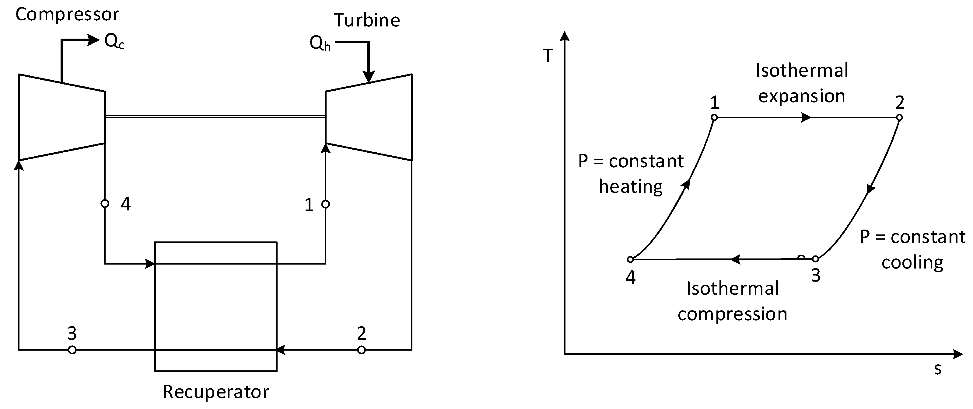
In principle, the NIHT cycle resembles the Ericsson cycle, schematically depicted in Figure 2, consisting of isothermal heat withdrawal (Qc) and injection (Qh) through isothermal compression and expansion of a working fluid, followed by a constant pressure recuperative heat exchange. The cycle is designed for maximum theoretical Carnot efficiency, when the components carry out reversible processes, with calculations applicable to a gas turbine with external combustion demonstrating the impressive efficiency gains achievable [15]. However, internal heat addition via combustion during expansion and heat removal during compression are necessary to achieve a workable large-scale solution, which is technologically challenging. Very limited work has been done on the concept of near-isothermal expansion in gas turbines with internal combustion. A relatively old thesis [16] investigated the idea numerically for application to aviation turbines fueled by kerosene. Computational fluid dynamics simulations were conducted with fuel injection at various points on the stator and rotor blades, with rotor injection achieving the most isothermal behavior. Both thermal efficiency and specific work were found to increase, and increased thermal loads on the blades were the main concern, although injection close to a recirculation zone could alleviate this issue. Another old study investigated near-isothermal expansion in a combined cycle setup, finding that very high pressure ratios are necessary to lower turbine outlet temperatures sufficiently such that the reduction in combustion irreversibility is not canceled out by the increase in heat transfer irreversibility [17]. Alternatively, higher steam cycle temperatures can also reduce heat transfer irreversibility [17], suggesting that a recuperator could be a good choice, as it can recover heat at a higher temperature than a steam cycle. On the other hand, studies evaluating the effect of compressor blade cooling to perform isothermal rather than adiabatic compression have been carried out [18], indicating that heat transfer rates may be limiting the efficiency gains achievable. Recently, efforts to develop isothermal compression technology have gained greater relevance as a result of the advent of liquid air storage systems [19].
In the present study, the NIHT is employed in the intercooled, reheated, regenerative Brayton cycle configuration illustrated in Figure 3. The NIHT cycle is configured as a two-shaft turbomachine where the first expansion stage drives the high-pressure compressor, while the remaining expansion stages drive the first low-pressure compressor stage and are coupled to a generator. The intermediate pressure ratio is selected to maximize process efficiency by maximizing heat recovery effectiveness between the HSRG and the air recuperator. The model assumes three reheated stages after hydrogen fuel injection and a fourth adiabatic stage prior to the recuperator, where a large temperature drop takes place, under the assumption that the maximum air preheat temperature is limited to 800 °C due to material limitations. Such configurations have been investigated for a long time [20] but have not found a competitive position in stationary power production where combined cycles dominate because of their high efficiency without requiring any modification to the gas turbine engine. Since the gas turbine engine is an extremely complex machine to tune, any cycle configuration that requires modification of the turbomachines involves high development costs, which represent a strong barrier to market entry. Still, there have been attempts to commercialize such cycles, indicating that competitiveness with well-established combined cycle technology is close, and the NIHT concept could tip the scales in favor of the recuperated cycle.
To maximize heat recovery efficiency, the cycle configuration also raises steam for blade cooling, as opposed to air cooling and compressor air extraction. Such additional heat recovery is beneficial because of the divergent temperature profiles in the recuperator owing to the much larger flow rate of the turbine outlet gases relative to the incoming air stream. Given the larger heat capacity of steam, steam cooling results in a comparatively smaller flow rate compared to a case where air is used.

1.2. Intercooled Recuperated Water-Injected Cycle

The intercooled recuperative cycle (ICR) is a compelling option for flexible power production because it combines the excellent part-load performance typical of recuperative cycles with the high insensitivity to ambient temperature afforded by intercooled compression. However, it has some limitations: it does not significantly increase power density to reduce specific costs, nor does it allow for complete heat recovery from flue gas, which is necessary to approach the efficiency levels of combined cycle gas turbines (CCGT). These limitations can be overcome by the intercooled recuperated water-injected (IRWI) cycle, as highlighted in previous studies [21,22].
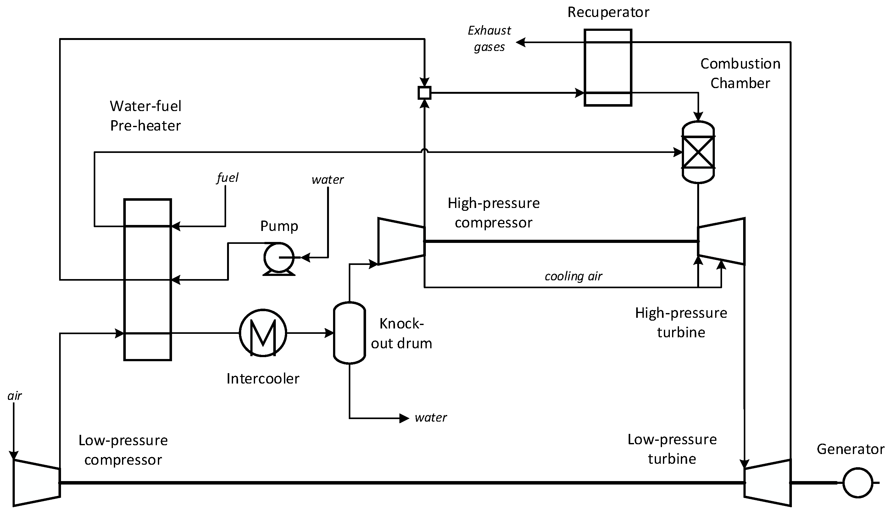
The plant flow diagram, illustrated in Figure 4, represents a two-shaft power unit designed to achieve an overall pressure ratio of 45, selected to optimize efficiency for the given turbine inlet temperature (TIT). A multi-shaft arrangement is also adopted by the Rolls-Royce WR-21 gas turbine, which is the only intercooled recuperative cycle (ICR) built and operated in recent years (since the early 2000s) as the core of the propulsion system for the United Kingdom’s Type 45 destroyer [23,24]. However, while the WR-21 largely relies on aeroderivative components, this analysis assumes that better economies of scale could be achieved for the power generation industry by using components from large, heavy-duty gas turbines, following the approach proposed by Nakhamkin et al. [25].
In this cycle, an intercooler situated between the low-pressure (LP) and high-pressure (HP) compressors preheats water and fuel using hot air from the first compressor. Air flow at the HP compressor exit is mixed with hot water from the preheater and routed to a recuperator where the liquid water is vaporized and heated up with the air to a temperature of approximately 500 °C, prior to entering a combustion chamber. The hot gases are expanded in a high-pressure turbine, which drives the high-pressure stage compressor, and subsequently in a low-pressure turbine, which delivers power to the low-pressure compressor stage and to a generator. The exhaust hot gases at approximately 540 °C are then routed to the recuperator. Cooling flows for blade refrigeration are withdrawn at several pressure levels of the high-pressure compression and from that stage discharge, amounting to around 23% of the compressor air intake. This flow distribution enables a hot end temperature approach in the recuperator, thereby reducing thermodynamic losses and achieving a final outlet gas temperature of around 200 °C.

2. Methodology

This section presents the process modeling assumptions and the cooling flow model, followed by a description of the economic assessment methodology. This methodology is consistently applied to a range of power plants, including a natural gas combined cycle (NGCC), an NGCC plant with post-combustion CO2 capture with monoethanolamine absorbent (MEA-NGCC), a hydrogen-fueled combined cycle (H2CC), the H2-fueled NIHT cycle and an enhanced variation (NIHT+), and the IRWI cycle fueled by natural gas and hydrogen.

2.1. Process Modelling

Process models of the aforementioned power cycles were developed in Unisim Design R481, using the Politecnico di Milano GS code from the Group of Energy Conversion Systems to validate the gas turbine components. The thermodynamic package employed in the Unisim software is the Peng-Robinson equation of state using a modified set of coefficients in the specific heat correlations adjusted to fit the JANAF database for enthalpy calculations, for a consistent comparison with output from the GS code. A lumped cooling flow model based on Jonsson et al. [26] was developed in Unisim Design to predict the air flow rates for gas turbine blade cooling. Certain technological assumptions were made in order to construct the models of the novel cycles, based on the outcomes of the calibration for existing turbomachinery from the GS code. These assumptions are based on H-class gas turbine technology using natural gas as fuel, where the main characteristics are reflected in Table 1.
The results of the calibration for this turbomachine are provided in Table 2. For a comprehensive comparison between the subsequent cases, the TIT was kept the same for all power cycles evaluated, and the size of each cycle was constrained to reach the same volumetric outlet flow as the H-class turbine. However, for the NIHT configurations, the air intake was modified to achieve 63% of the volumetric outlet flow of the NGCC case, which is the relation between the 3rd and 4th rotor flow areas of the H-class gas turbine. The rationale is that the turbine outlet temperature of the NIHT is approximately 840 °C, similar to the exit of the 3rd stage of an H-class gas turbine. To withstand this temperature, the features of the last stage of the NIHT cycle turbine are expected to be closer to the 3rd rather than to the 4th stage of an H-class gas turbine.
The steam cycle process assumptions and efficiencies for the combined cycle configuration are consistent with prior published work [14]. The bottoming cycle consists of a three-pressure level heat recovery steam generator (HSRG) with intermediate reheat. The post-combustion capture scope added to the MEA-NGCC case was developed based on EBTF [27] guidelines and assumptions. Finally, several additional process modeling assumptions for the novel NIHT and IRWI power cycles were considered, as reflected in Table 3.
The enhanced NIHT+ cycle assumes that all H2 fuel is injected in the 1st stator while achieving the required fuel conversion in each stage so that the inlet rotor temperature corresponds to the TIT calibrated for the H-class turbine. This effectively increases the volumetric flow across the expansion path, resulting in a larger power output compared to the base case with sequential fuel injection. Additionally, high-pressure steam at 120 bar and 500 °C is raised in the HSRG and expanded in a backpressure turbine to the pressure required by the cooling steam used in 2nd stage of the NIHT turbine, thereby producing extra power and improving heat recovery performance. A pressure level in the HSRG for steam cooling of the 1st stage of the NIHT turbine was maintained, which resulted in the gas turbine’s overall pressure ratio with a small overpressure.

2.2. Blade Cooling Flow Model

Blade cooling flows are often estimated by the following correlation applied to each row of stators and each row of rotors [28]:
m ˙ c c ¯ p , c m ˙ g c ¯ p , g = b T g T b T b T c
The required coolant flow rate, m ˙ c [kg/s], increases proportionately with the hot gas flow rate across the blade row, m ˙ g [kg/s], and the difference between the hot gas temperature, T g [K], and the maximum blade temperature, T b [K], while scaling inversely proportionally to the difference between the blade temperature and the coolant temperature, T c [K]. The factor b is an empirical constant that can be tuned, largely depending on the efficiency of the cooling design. Due to the large irreversibility of injecting a cold coolant into a hot gas stream, the objective is to minimize the required coolant flow. This can be done via technological advances to increase T b and decrease b . Active research in the field of gas turbine blade cooling [29] and materials [30] could further improve these numbers to reduce cooling flow requirements. Alternatively, there is a trade-off involved in decreasing T g or T c to decrease the coolant flow in exchange for lower expander power output and greater irreversibility in the mixing of cold and hot streams. The blade temperatures considered were 900 °C for 1st row stator and 875 °C for the 1st row rotor of the H-class turbine, while the remaining rows assumed a stator and rotor temperature of 870 °C and 845 °C, respectively [31]. For the NIHT cycles, it was assumed that the three reheated stages comprised stator and rotor rows with blade temperatures corresponding to the values of the 1st stage H-class turbine, while the 4th stage blade temperatures are equivalent to the 2nd and subsequent stages of the H-class turbomachine.
This correlation was adjusted for application to the stators and rotors in the NIHT and H2-fueled IRWI cycles by tuning against the cooling flows predicted by detailed gas turbine simulations for five different gas turbine configurations: (1) standard H-class pressure ratio of 23.6 with 4 blade rows, (2) pressure ratio of 15 with 4 blade rows, (3) pressure ratio of 15 with 3 blade rows, (4) pressure ratio of 45 with 5 blade rows, and (5) pressure ratio of 45 with two shafts having 3 and 2 blade rows, respectively. The adjustment showed that the standard correlation could be used for the stators (Equation (2)), while a small modification to the temperature dependency and an adjustment for the pressure was needed for the rotors (Equation (3)).
Stators :   m ˙ c c ¯ p , c m ˙ g c ¯ p , g = 0.042 T g T b T b T c
R o t o r s :   m ˙ c c ¯ p , c m ˙ g c ¯ p , g = 0.042 T g T b T b T c 1.1 / P g 0.182
Here, P g [bar] is the geometric mean of the pressure at the start and end of the blade row.
Another influential parameter is the pressure at which the coolant needs to be injected, i.e., the extraction pressure from the compressor, P c [bar]. In this case, the correlations derived for the stators and rotors are as follows:
Stators :   P c P g = 0.0783 m ˙ c 0.62 P g 0.66
R o t o r s :   P c = 1.33 P g
Here, P g is the blade row inlet pressure for the stators and the geometric mean of the row inlet and outlet pressures for the rotors.

2.3. Economic Assessment

The economic assessment was carried out using a bottom-up approach employing the SEA tool v1.4 [32] based on correlations from Turton et al. [33]. For the power plants, gas turbine costs were the most important component, of which the equipment cost was determined using the following formula derived from prices in the 2020 Gas Turbine World handbook [34]:
55240 m ˙ a i r 0.7 P G T 0.34 R G T 0.1 1 + 0.08 S 1 + 0.2 I 1.68 / 1.1
Here, m ˙ a i r [kg/s] is the air mass flow rate going through the turbine, P G T [kJ/kg] is the power density of the gas turbine, R G T is the gas turbine pressure ratio, S is a switch for whether the turbine has one shaft S = 0 or two shafts S = 1 , and I is a switch for whether I = 1 or not I = 0 the gas turbine has intercooled compression. The factor 1.68 is the installation factor of the turbine [27], and the factor 1.1 is the $/€ conversion rate.
For the cases considering fuel supply costs, the costs in Table 4 were employed. Although there is great variability in the fuel transmission distance and scale and the cavern storage volume, the present study assumed that fuel would be transported for 500 km in large pipelines of the scale given in Table 4 and another 50 km in smaller pipelines to the plant location where the specific cost is increased due to uneconomies of (smaller) scale using a scaling exponent of 0.5. In addition, the plant is assumed to need fuel storage equivalent to 3 days of full power output in underground caverns to handle the variability of wind and solar.
Other general assumptions employed in the economic assessment are shown in Table 5.

3. Results

This section will be presented in three parts: technical, economic, and the effect of capacity factor on plant economics (with and without the cost of delivering the gaseous fuel).

3.1. Technical Performance

Table 6 shows the power output and efficiency of the different power cycles evaluated. The NGCC benchmark with the off-the-shelf H-class gas turbine achieves a standard LHV efficiency of 62.1% with more than two-thirds of the power coming from the gas turbine and the remainder from the steam turbines in the bottoming cycle. An open cycle configuration (NGOC) using the same gas turbine without a bottoming cycle was also assessed. When adding post-combustion CO2 capture to the NGCC plant (MEA-NGCC), the power output from the bottoming cycle declines due to steam extraction for the MEA stripper, and the auxiliary power demand increases, mainly due to the CO2 compressors. The overall energy penalty for CO2 capture is 7.8% points. Using hydrogen instead of natural gas as fuel in the combined cycle power plant achieves a 1.1%-point gain in efficiency due to the higher specific enthalpy drop for equivalent pressure ratio and TIT when expanding water-enriched gases that result from hydrogen combustion, relative to methane.
The two NIHT cycles deliver similar power from the gas turbine as the combined cycle plants, even though the turbine architecture differs strongly. As shown in Table 7, the multiple reheats in the NIHT allow the same power to be produced with a 2.6 times lower air flow, making the turbine considerably smaller with a very high specific power. The air flow rate was limited to achieve a similar volumetric flow rate at the turbine outlet to that of the second-to-last row of the conventional H-class turbine, which corresponds approximately to the outlet temperature of the NIHT. The effect of improved economies of scale in case the turbine can be larger will be explored in the next section. Table 6 also shows the high ratio of expansion to compression power of the NIHT cycles where the near-isothermal expansion facilitates high power output from a given amount of compressed air and the intercooled compression reduces the relative compression power. In terms of efficiency, the NIHT cycle delivers similar performance to the combined cycles, indicating that the recuperation can deliver similar efficiency benefits to the bottoming cycle. These benefits are enhanced in the NIHT+ cycle, which significantly outperforms the combined cycles in terms of efficiency as a result of the first stage fuel injection to increase the volumetric flow across the expansion path, and the backpressure steam turbine after the HSRG, which maximizes power output. Notably, the steam expansion in this unit to relatively high outlet pressures of approximately 25 bar results in a small equipment size compared to combined cycle steam turbines with typical expansions to vacuum pressures, resulting in large volumetric outlet flows.
The IRWI cycle achieves a very high power output from the gas turbine due to the large amount of water injection increasing the power delivery of the expander, while the compression power remains similar to that of the conventional H-class machine (Table 6). Despite not having a bottoming cycle, the IRWI cycle delivers the highest power output of the evaluated plants. Even though the added steam significantly increases the mass flow at the turbine outlet relative to the conventional H-class turbine, the volumetric turbine outlet flow is similar because the IRWI cycle has a lower turbine outlet temperature, suggesting that such large turbine power outputs should be feasible with an expander geometry similar to established technology. The efficiency is also reasonable—only 3.8% points below the combined cycle benchmarks, indicating that the strongly simplified heat recovery section of this concept can almost replicate the performance of a considerably more complex bottoming cycle. Similar to the combined cycles, the IRWI cycle powered by hydrogen achieves a 1.1%-point greater efficiency than the equivalent turbine powered by natural gas.
Table 7 indicates that the NIHT and IRWI cycles use a considerably higher pressure ratio, requiring two shafts and intercooled compression. This more complex gas turbine design will cancel out some of the economic benefits of the high specific power delivered by these machines, as will be discussed in the following section.
Finally, a brief discussion on operational flexibility will be presented because the capacity for rapid startup and ramping is essential for operation next to high shares of variable renewables. Overall, the IRWI cycle is expected to be significantly more flexible than modern combined cycle benchmarks, as it avoids the steam cycle and presents a significantly higher power density. The multi-shaft design adds complexity but may facilitate faster ramping thanks to the faster acceleration of the HP spool [38]. The NIHT can offer even faster ramping due to its very high power density, but startup may be more challenging due to the requirement of steam cooling. Thus, a combustor or steam storage will be required to provide blade cooling for a few minutes under startup until hot turbine outlet gases are available for steam generation. At 30 €/kWh [39], 15 min of steam storage under startup will inflate the NIHT cycle capital costs by less than 1%. Combustion in the expansion path may present additional constraints on flexibility for the NIHT concept, both regarding NOx formation and combustion rate for maintaining isothermal expansion. Experimental studies will be required to further elucidate these challenges.

3.2. Economic Performance

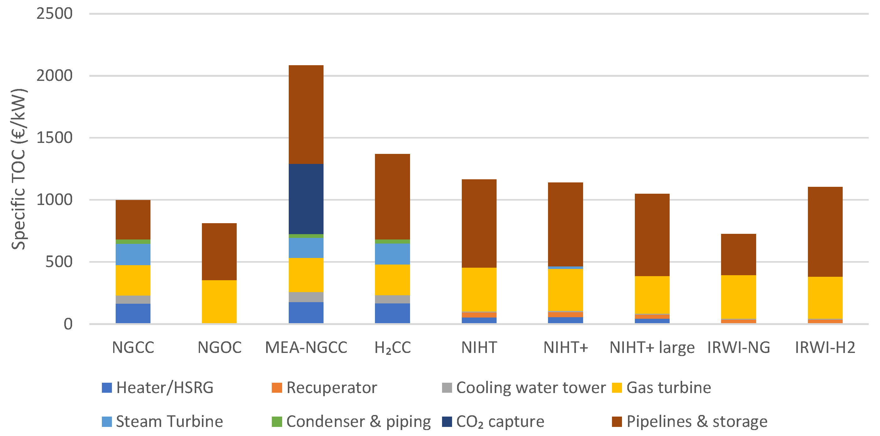
The capital cost breakdowns of the different plants are shown in Figure 5. The first noticeable feature is the prominent contribution of pipelines and storage for secure fuel supply and CO2 handling. This important cost component is often neglected, and it becomes particularly important when discussing hydrogen, which is considerably more expensive than natural gas to handle. For example, the pipeline and storage capital cost for the H2CC plant is more than twice that of the NGCC plant. The present study will present results with and without accounting for this important, but also highly uncertain, cost component. The impact of pipeline distance and storage size was investigated in a previous study by the authors [14].
Aside from the MEA-NGCC plant, where the CO2 capture system is the next-largest capital cost component, the gas turbine contributes the second-most important cost. The combined cycle plants have somewhat lower gas turbine costs than the open or recuperated cycle plants, but adding the cost of the steam turbines increases the total turbomachine cost well above that of the novel NIHT and IRWI cycles. The NIHT and NIHT+ cases have a somewhat higher gas turbine cost than the IRWI cycle, largely because of their smaller scale. If the NIHT cycle can be scaled to the size of the IRWI cycle (NIHT+ large in Figure 5, its very high power density gives it a lower specific capital cost.
Heat recovery and rejection also become much cheaper in the novel cycles. A relatively large temperature difference was assumed in the recuperator to minimize its cost and to respect material temperature limits, and the steam generation section is much smaller than it would be in a combined cycle power plant. The high power density of the novel power cycles strongly reduces the amount of gas that needs to pass through the heat recovery section, further reducing the size of the stack and associated costs. In addition, these cycles reject heat directly to the environment via the exhaust gas, avoiding the need for a condenser and cooling tower. Relative to NIHT, IRWI offers considerable savings in the low-temperature water heater because only water economization is required, whereas the NIHT concept requires evaporation and superheating.
Overall, the novel power cycles reduce specific capital costs almost down to the level of an open cycle configuration, only without the considerable efficiency sacrifices. However, since most of these plants operate with hydrogen, this capital cost benefit is more than canceled out by the large cost of fuel pipelines and storage for ensuring a reliable fuel supply. The novel cycle operating on natural gas (IRWI-NG) has the lowest total capital costs because it further reduces fuel supply costs relative to the NGOC plant thanks to its higher efficiency.
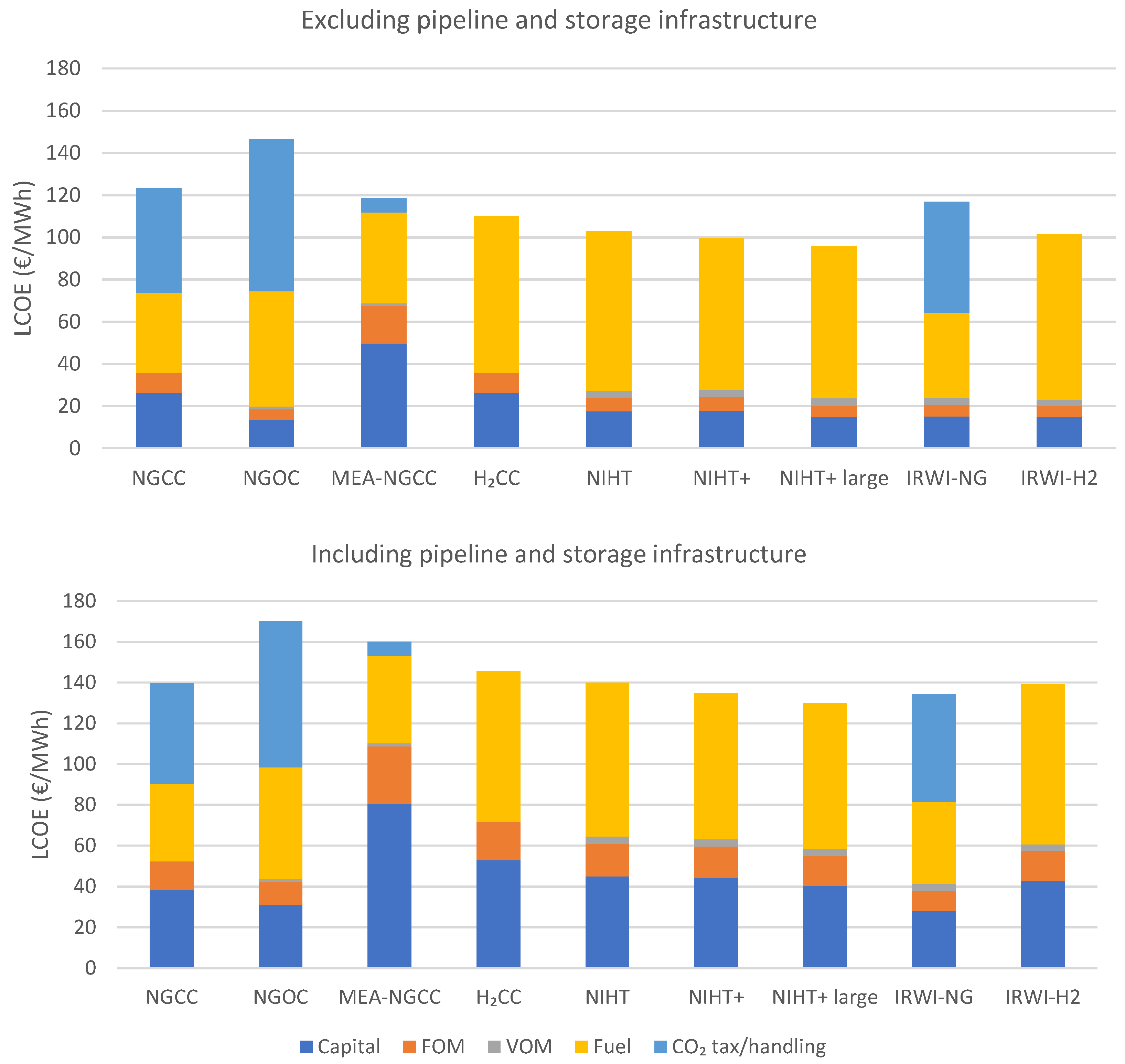
Figure 6 shows the broader economic performance of the different cycles via the levelized cost of electricity at a low capacity factor of 30%, relevant for gas-fired power plants in renewable-rich electricity systems. When pipeline and storage infrastructure is neglected, the advanced cycles using hydrogen fuel have a clear economic advantage. Under the assumed natural gas and hydrogen prices, carbon-free hydrogen fuel breaks even with natural gas combustion (and the associated direct emissions) at a CO2 price of 114 €/ton, so the chosen CO2 price of 150 €/ton gives the advantage to hydrogen fuel. In addition, Table 6 shows that hydrogen leads to slightly more efficient power production (comparing the H2CC and NGCC power plants), extending the advantage. Furthermore, the significant capital cost savings of the advanced plants relative to the H2CC plant (Figure 5) further reduces the LCOE in the case of the NIHT and IRWI plants. For example, the large NIHT+ plant can break even with the NGCC plant at a CO2 price of only 67 €/ton.
The NGOC plant is much more expensive than the NGCC plant because of the large CO2 emissions tax levied on its higher specific emissions. Without CO2 taxes, the LCOE of NGOC and NGCC would be similar, and NGOC would increasingly be the preferred option as the capacity factor reduces further.
Adding CO2 capture in the MEA-NGCC plant slightly reduces the cost relative to the NGCC plant, implying a high CO2 avoidance cost of 135 €/ton. This high cost is largely due to the high capital cost of the MEA-NGCC plant, which makes it uneconomical at the low capacity factor (30%) assumed. In general, power plants with CCS are better suited to steady operation at a higher capacity factor.
Among the advanced H2-fired plants, the simpler IRWI cycle compares well with the NIHT cycle. Only in the case that the NIHT+ cycle can be scaled to the same power output as the IRWI cycle, thereby reducing capital costs to a similar level, does NIHT offer a clear economic advantage due to its higher efficiency reducing fuel costs. IRWI also has slightly lower VOM than NIHT because of slightly lower water consumption. Although water constitutes a minor cost under the present European assumptions, the water demand of NIHT and IRWI could represent a higher cost (and environmental impact) in dry regions. It is also worth noting that the IRWI-NG plant offers slightly better performance than the NGCC plant because its lower capital costs, which become increasingly important at low capacity factors, cancel out higher fuel and emissions costs from its lower efficiency.
The inclusion of pipeline and storage infrastructure for supplying fuel and removing CO2 changes the picture considerably. The NGCC plant is the least affected because delivering natural gas to the plant is not as expensive. The NGOC further loses competitiveness to the NGCC plant because its lower efficiency requires more fuel supply infrastructure per unit of power produced. The MEA-NGCC plant also loses competitiveness because of the lower efficiency requiring more fuel supply infrastructure and the addition of CO2 handling infrastructure. Although the IRWI-NG plant has slightly higher fuel supply costs due to its lower efficiency, it still offers lower levelized costs than the NGCC benchmark.
The high cost of hydrogen pipeline and storage infrastructure shown in Figure 5 worsens the economic case for all H2-fired power cycles relative to natural gas-powered benchmarks. Whereas the H2CC plant was significantly cheaper than NGCC without fuel supply infrastructure considered, it is now considerably more expensive. The advanced H2 cycles still offer a significant benefit, but the basic NIHT and IRWI cycles only barely break even with NGCC under the selected assumptions. The NIHT+ cycle’s improved efficiency also lowers fuel supply costs, making it a slightly improved proposition. Due to the significant efficiency advantage of NIHT+ over IRWI, the LCOE advantage of the fully scaled NIHT+ cycle grows further. However, the CO2 avoidance cost of the large NIHT+ cycle relative to the NGCC benchmark grows from 67 €/ton without accounting for fuel supply infrastructure to 121 €/ton when fuel supply costs are added. Similar to the combined cycles, the addition of fuel supply infrastructure costs makes the IRWI-NG plant cheaper than the IRWI-H2 plant.
An additional factor that could erode the business case for advanced H2-fired power plants is a high premium on H2 fuel relative to NG. The base H2 price assumption in Table 5 assumes advanced blue H2 production pathways such as gas switching reforming [40] or membrane-assisted autothermal reforming [41]. Conventional blue H2 production would be 10–20% more expensive [42], and green hydrogen would be considerably more expensive still. Figure 7 shows that H2-fired plants start losing competitiveness relative to the NGCC benchmark in the 15–18 €/GJ H2 price range when the CO2 price is set to 150 €/ton, even without accounting for fuel supply costs. Thus, a loss in competitiveness due to the high costs of H2 fuel is an important factor to consider in H2-fired concepts.
Thus, the H2-fired concepts can be disadvantaged by high fuel production costs or high fuel distribution and storage costs. Limiting these costs is essential for the commercial viability of these concepts. On-site hydrogen production would eliminate the need for costly hydrogen transmission and storage. However, operating these plants at low capacity factors to intermittently supply fuel to flexible power plants would strongly inflate the hydrogen production cost and introduce technical challenges to the hydrogen production process. One potential solution is flexible power/hydrogen production from natural gas [9] or solid fuels [43] where the hydrogen production process operates continuously, using the hydrogen product for power production when electricity is scarce and exporting it to the market when electricity is abundant. When coupled with a power cycle operating at a low capacity factor, the pipelines exporting hydrogen from this flexible plant can still be utilized at a reasonably high capacity factor, limiting hydrogen handling costs. However, such an arrangement requires a sufficiently large market for consuming the exported hydrogen.

3.3. Effect of Capacity Factor

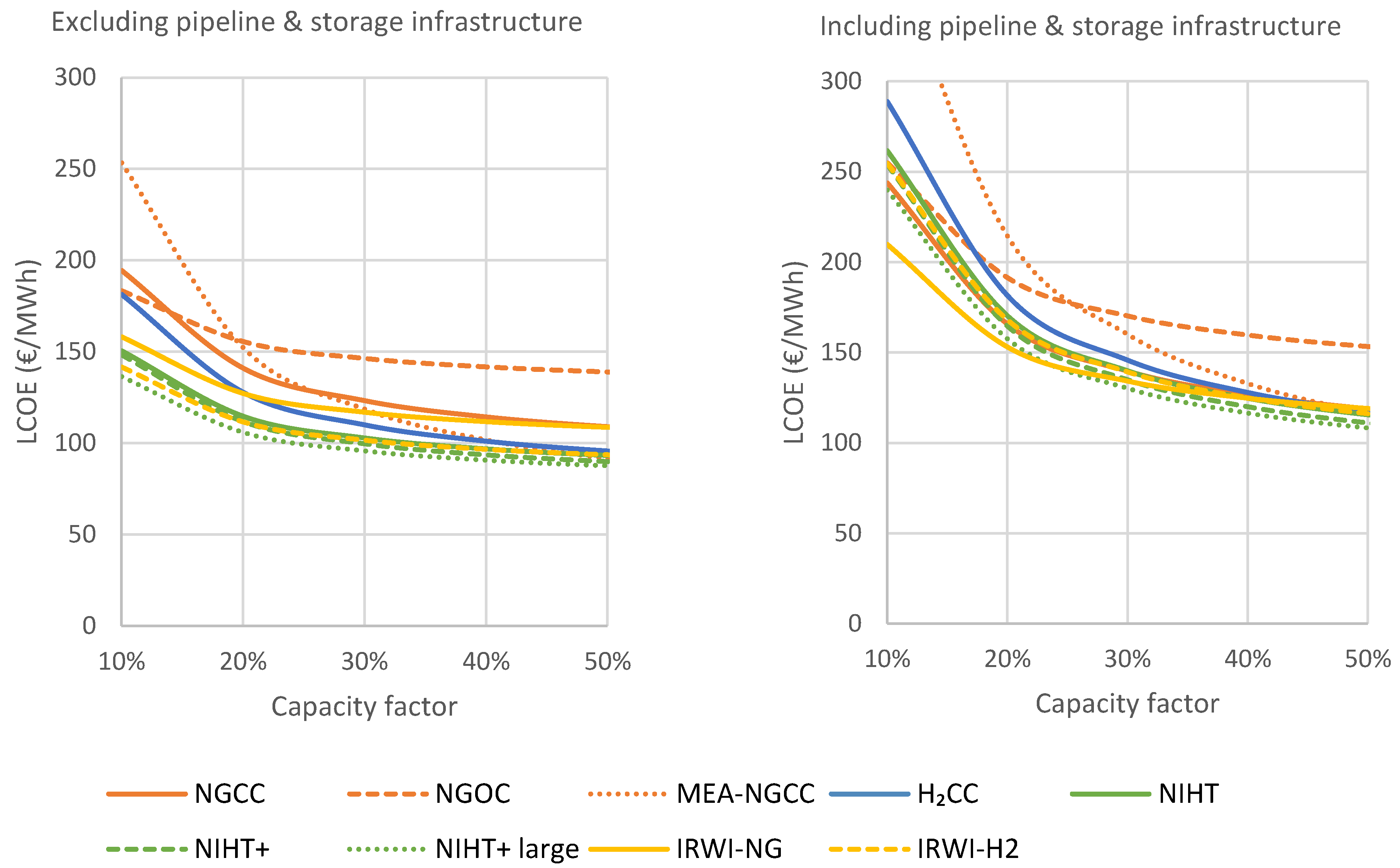
Figure 8 shows that, when pipeline and storage infrastructure are excluded, lower capacity factors increasingly favor the plants with lower capital costs, i.e., the OCGT and the advanced H2 cycles. The more capital-intensive MEA-NGCC becomes more competitive at higher capacity factors.
However, including fuel supply infrastructure cancels out the capital cost advantage of the advanced H2 plants relative to the NGCC plant (Figure 5). Hence, the response to changes in the capacity factor is similar between the different plants. At the lowest capacity factor considered (10%), not even the fully scaled NIHT+ cycle can outcompete the standard NGCC plant. Under such operating conditions, the IRWI-NG plant offers a considerable economic advantage because it is substantially less capital-intensive than the NGCC plant with only slightly reduced efficiency.
The large effect of including pipeline and storage infrastructure on the conclusions shows the importance of this often neglected and highly uncertain factor. For power plants located close to the fuel supply, the standard conclusion that plants with a low capital cost will become increasingly competitive at lower capacity factors will still hold. However, a significant distance from the fuel source, or a high need for energy security (and the associated fuel storage requirement), strongly reduces the case for cheaper power cycles operating at a lower efficiency, especially when hydrogen is used as fuel.
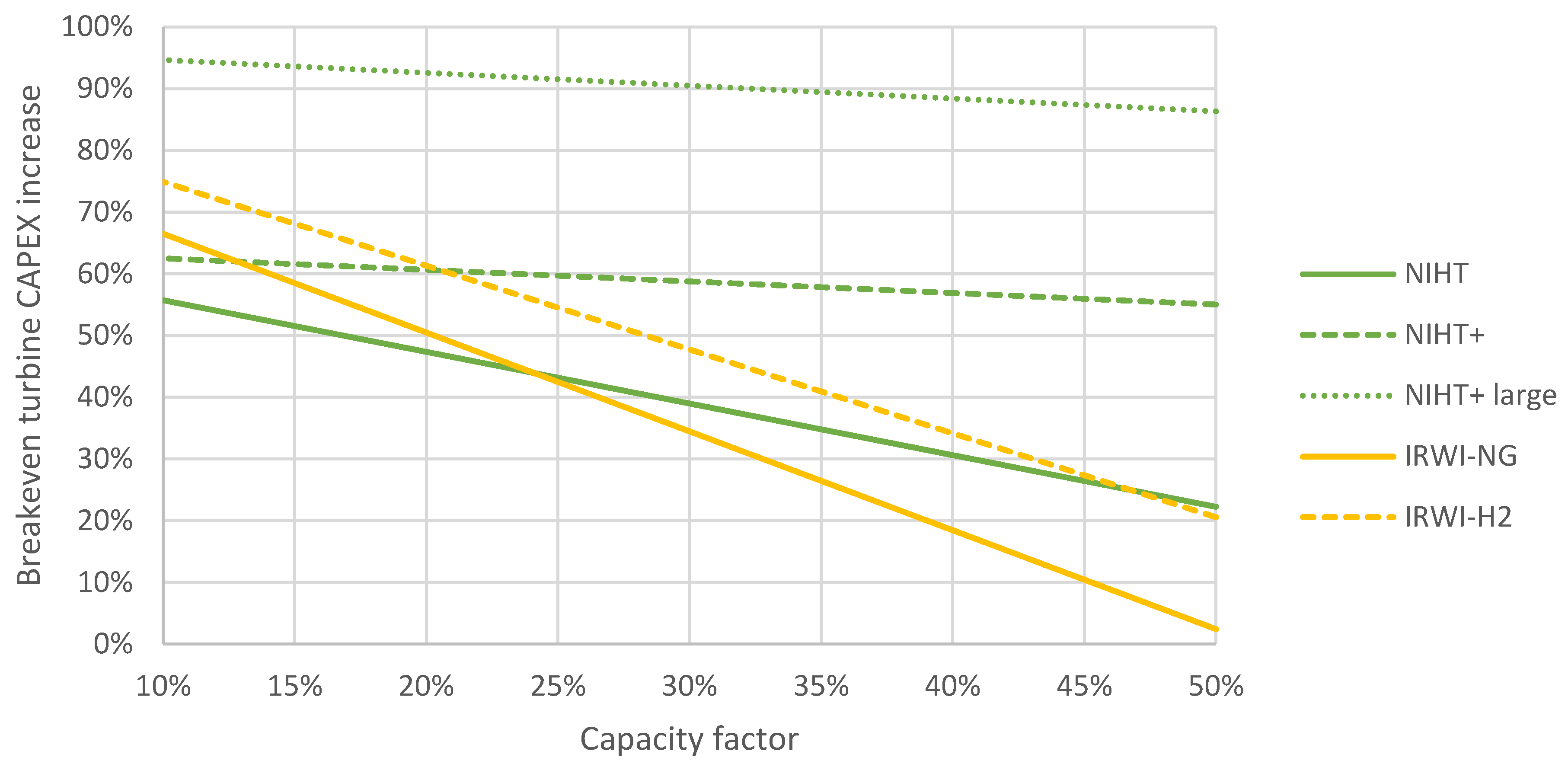
Finally, another important sensitivity will be evaluated in Figure 9: the level of cost inflation of the novel turbines that would erode their cost advantage relative to established combined cycle technology. Estimating the cost of novel turbine technology is difficult, and a large amount of trial-and-error learning may be required before the novel machines are optimized and refined to the same degree as the H-class machines used in the combined cycle benchmarks. The IRWI cycles show a strong dependency on the capacity factor because their attractively low capital costs come at a significant efficiency penalty. As the capacity factor reduces, the efficiency penalty becomes less influential, as capital costs have a larger weight on the LCOE, thereby permitting greater novel turbine cost inflation before the business case is eroded. The NIHT cycles have a higher efficiency, preserving their economic benefit also at higher capacity factors. In particular, the NIHT+ cycle that has a slightly higher efficiency than H2CC shows little sensitivity to the capacity factor, maintaining its economic advantage over H2CC even when 50% additional costs are assumed for the gas turbine. If the NIHT+ cycle can be scaled to the same power output as the IRWI cycle, almost a doubling of the estimated turbine cost can be permitted before the LCOE rises to the level of the combined cycle benchmark.

4. Conclusions

In this work, novel power cycle designs were investigated from a techno-economic perspective. The near isothermal hydrogen turbine (NIHT) pursues the theoretically ideal cycle for a direct power-producing thermal machine, carrying out an intercooled compression of the working fluid, heat recuperation, and quasi-isothermal expansion by the sequential combustion of a carbon-free fuel (hydrogen) across the expansion path. The principle is that the fast-burning hydrogen fuel can be near-isothermally combusted in the expansion path without concerns about incomplete combustion and CO emissions. On the other hand, the intercooled recuperated water-injected (IRWI) cycle increases the flow rate across the expansion path to maximize power output by economizing water in a compressor intercooler and, after mixing with the air compressor discharge, vaporizing it in a recuperator against the turbine exhaust flow, achieving an effective heat recovery while avoiding the bulky elements (condenser, steam turbine) of a Rankine cycle in a combined cycle power plant.
Both novel cycles were proposed for the purpose of economical operation at low capacity factors for integrating high shares of wind and solar power. When only considering the power plant infrastructure, both configurations show promise, achieving similar efficiency to a combined cycle with considerably lower capital costs. Compared to a conventional combined cycle benchmark, the novel cycles showed 7–13% lower power production costs when operating at a capacity factor of 30%. Lower capacity factors further extend this advantage due to the lower capital cost of the novel cycles.
Most of the novel power cycles were simulated with hydrogen fuel to avoid CO2 emissions. Under the assumed fuel costs (6.5 €/GJ for natural gas and 13 €/GJ for hydrogen) and CO2 price (150 €/ton), hydrogen firing was clearly more profitable than natural gas firing. Specifically, the proposed hydrogen-fueled cycles could avoid CO2 for 67–85 €/ton relative to a natural gas combined cycle (NGCC) benchmark at a capacity factor of 30%. However, increases in the cost of H2 fuel quickly erode the attractiveness of H2-fueled plants, reaching parity with NGCC in the 15–18 €/GJ H2 price range.
Furthermore, the storage and transmission infrastructure required for reliable fuel supply adds substantial capital costs to hydrogen-fired power plants because the low volumetric energy density of hydrogen makes it costlier to handle than natural gas. Under the assumption that the plant is located 550 km away from the fuel source and requires storage for at least three days at full capacity, the additional fuel supply costs erode the economic benefits of the proposed hydrogen-fired power cycles.
In conclusion, promising new hydrogen-fueled power cycles should only be considered in cases where the plant is located close to a reliable fuel supply and a reliable and low-cost hydrogen fuel supply is secured. Unless flexible hydrogen/power production concepts are commercialized, natural gas firing will be more profitable in most cases, even if the use of hydrogen fuel enables advanced designs like NIHT. In this event, the IRWI plant fired by natural gas appears to be a promising solution for the integration of high wind/solar shares.

Author Contributions

Conceptualization, S.C. and P.C.; methodology, C.A.d.P., S.C., P.C. and Á.J.Á.; software, P.C. and Á.J.Á.; validation, C.A.d.P., S.C., P.C. and Á.J.Á.; formal analysis, C.A.d.P., S.C. and P.C.; investigation, C.A.d.P., S.C. and P.C.; resources, Á.J.Á.; data curation, C.A.d.P. and S.C.; writing—original draft preparation, C.A.d.P. and S.C.; writing—review and editing, P.C. and Á.J.Á.; visualization, C.A.d.P. and S.C.; funding acquisition, Á.J.Á. All authors have read and agreed to the published version of the manuscript.

Funding

This research received funding from the European Union NextGenerationEU, Ministerio de Universidades grant RD 289/2021 (UP2021-035).

Data Availability Statement

Raw data will be provided upon request.

Acknowledgments

The authors would like to acknowledge Honeywell for the free academic license of Unisim Design R481.

Conflicts of Interest

The authors declare no conflicts of interest.

Nomenclature

Acronyms:
BECBare erected cost
CCCombined cycle
CCSCarbon capture and storage
COTCombustor outlet temperature
EPCEngineering procurement and construction
FOMFixed operating and maintenance
HSRGHeat recovery steam generator
IRWIIntercooled recuperated water-injected cycle
LCOELevelized cost of electricity
LHVLower heating value
MEAMonoethanolamine
NGNatural gas
NGCCNatural gas combined cycle
NGOCNatural gas open cycle
NIHTNear isothermal hydrogen turbine
OCOwner’s costs
PTProject contingency
SEAStandardized economic assessment
TITTurbine inlet temperature
TOCTotal overnight cost
VOMVariable operating and maintenance
List of symbols
b Blade cooling empirical constant (-)
T Temperature (K)
Q Heat duty (MW)
m ˙ Mass flow (kg/s)
c p Specific heat capacity (kJ/kgK)
P g Geometric mean pressure (bar)
P c Compressor extraction pressure (bar)
P G T Gas turbine power density (kJ/kg)
R G T Gas turbine pressure ratio (-)
Subscripts/Superscripts
b Blade
g Hot gases
c Coolant

References

  1. IEA. World Energy Outlook; International Energy Agency: Paris, France, 2023. [Google Scholar]
  2. IPCC. Climate Change 2022: Mitigation of Climate Change. Contribution of Working Group III to the Sixth Assessment Report of the Intergovernmental Panel on Climate Change; IPCC: Geneva, Switzerland, 2022. [Google Scholar]
  3. NREL. Annual Technology Baseline: Natural Gas Plants. 2019. Available online: https://atb-archive.nrel.gov/electricity/2019/index.html?t=cg (accessed on 18 January 2024).
  4. Cloete, S.; Ruhnau, O.; Hirth, L. On capital utilization in the hydrogen economy: The quest to minimize idle capacity in renewables-rich energy systems. Int. J. Hydrog. Energy 2021, 46, 169–188. [Google Scholar] [CrossRef]
  5. van der Wijk, P.C.; Brouwer, A.S.; van den Broek, M.; Slot, T.; Stienstra, G.; van der Veen, W.; Faaij, A.P.C. Benefits of coal-fired power generation with flexible CCS in a future northwest European power system with large scale wind power. Int. J. Greenh. Gas Control 2014, 28, 216–233. [Google Scholar] [CrossRef]
  6. Oates, D.L.; Versteeg, P.; Hittinger, E.; Jaramillo, P. Profitability of CCS with flue gas bypass and solvent storage. Int. J. Greenh. Gas Control 2014, 27, 279–288. [Google Scholar] [CrossRef]
  7. Zaman, M.; Lee, J.H. Optimization of the various modes of flexible operation for post-combustion CO2 capture plant. Comput. Chem. Eng. 2015, 75, 14–27. [Google Scholar] [CrossRef]
  8. Mac Dowell, N.; Staffell, I. The role of flexible CCS in the UK’s future energy system. Int. J. Greenh. Gas Control 2016, 48, 327–344. [Google Scholar] [CrossRef]
  9. Cloete, S.; Hirth, L. Flexible power and hydrogen production: Finding synergy between CCS and variable renewables. Energy 2020, 192, 116671. [Google Scholar] [CrossRef]
  10. de Boer, H.S.; Grond, L.; Moll, H.; Benders, R. The application of power-to-gas, pumped hydro storage and compressed air energy storage in an electricity system at different wind power penetration levels. Energy 2014, 72, 360–370. [Google Scholar] [CrossRef]
  11. Moradi, R.; Groth, K.M. Hydrogen storage and delivery: Review of the state of the art technologies and risk and reliability analysis. Int. J. Hydrog. Energy 2019, 44, 12254–12269. [Google Scholar] [CrossRef]
  12. Cloete, S.; Arnaiz del Pozo, C.; Jiménez Álvaro, Á. System-friendly process design: Optimizing blue hydrogen production for future energy systems. Energy 2022, 259, 124954. [Google Scholar] [CrossRef]
  13. Nazir, H.; Muthuswamy, N.; Louis, C.; Jose, S.; Prakash, J.; Buan, M.E.; Flox, C.; Chavan, S.; Shi, X.; Kauranen, P.; et al. Is the H2 economy realizable in the foreseeable future? Part II: H2 storage, transportation, and distribution. Int. J. Hydrog. Energy 2020, 45, 20693–20708. [Google Scholar] [CrossRef]
  14. Arnaiz del Pozo, C.; Jiménez Álvaro, Á.; Cloete, S.; García del Pozo Martín de Hijas, J.A. The Potential of Chemically Recuperated Power Cycles in Markets with High Shares of Variable Renewables. Energies 2023, 16, 7046. [Google Scholar] [CrossRef]
  15. Kraszewski, B. On an improvement of Carnot-like cycles devoted to turbines with isothermal expansion. Trans. Inst. Fluid-Flow Mach. 2018, 140, 3–21. [Google Scholar]
  16. Rice, M. Simulation of Isothermal Combustion in Gas Turbines; Virginia Polytechnic Institute and State University: Blacksburg, VA, USA, 2004. [Google Scholar]
  17. El-Masri, M.A.; Magnusson, J.H. Thermodynamics of an Isothermal Gas Turbine Combined Cycle. J. Eng. Gas Turbines Power 1984, 106, 743–749. [Google Scholar] [CrossRef]
  18. Shah, P.N.; Tan, C.S. Effect of Blade Passage Surface Heat Extraction on Axial Compressor Performance. J. Turbomach. 2005, 129, 457–467. [Google Scholar] [CrossRef]
  19. Kim, T.; Lee, C.-Y.; Hwang, Y.; Radermacher, R. A review on nearly isothermal compression technology. Int. J. Refrig. 2022, 144, 145–162. [Google Scholar] [CrossRef]
  20. El-Masri, M.A. Thermodynamics and Performance Projections for Intercooled/Reheat/Recuperated Gas Turbine Systems. In Proceedings of the GT1987, Volume 2: Aircraft Engine; Marine; Microturbines and Small Turbomachinery, Anaheim, CA, USA, 31 May–4 June 1987. [Google Scholar] [CrossRef]
  21. El-Masri, M.A. A Modified, High-Efficiency, Recuperated Gas Turbine Cycle. J. Eng. Gas Turbines Power 1988, 110, 233–242. [Google Scholar] [CrossRef]
  22. Chiesa, P.; Lozza, G.; Macchi, E.; Consonni, S. An Assessment of the Thermodynamic Performance of Mixed Gas–Steam Cycles: Part B—Water-Injected and HAT Cycles. J. Eng. Gas Turbines Power 1995, 117, 499–508. [Google Scholar] [CrossRef]
  23. English, C.R.; McCarthy, S.J. Qualification Testing the WR21 Intercooled and Recuperated Gas Turbine. In Proceedings of the GT2001, Volume 1: Aircraft Engine; Marine; Turbomachinery; Microturbines and Small Turbomachinery, New Orleans, LA, USA, 4–7 June 2001. [Google Scholar] [CrossRef]
  24. Little, G.T.; Erskine, P.A.; Norton, P. Demonstrating the Electric Ship. Nav. Eng. J. 2003, 115, 91–105. [Google Scholar] [CrossRef]
  25. Nakhamkin, M.; Swensen, E.C.; Scheibel, J.R.; Cohn, A. CHAT Technology: An Alternative Approach to Achieve Advanced Turbine Systems Efficiencies With Present Combustion Turbine Technology. In Proceedings of the GT1998, Volume 3: Coal, Biomass and Alternative Fuels; Combustion and Fuels; Oil and Gas Applications; Cycle Innovations, Stockholm, Sweden, 2–5 June 1998. [Google Scholar] [CrossRef]
  26. Jonsson, M.; Bolland, O.; Bücker, D.; Rost, M. Gas turbine cooling model for evaluation of novel cycles. Proc. ECOS 2005, 2005, 641–650. [Google Scholar]
  27. Franco, F.; Anantharaman, R.; Bolland, O.; Booth, N.; van Dorst, E.; Ekstrom, C.; Sanchez Fernandez, E.; Macchi, E.; Manzolini, G.; Nikolic, D.; et al. European Best Practice Guidelines for CO2 Capture Technologies. 2011. Available online: https://www.ctc-n.org/sites/default/files/resources/d_4_9_best_practice_guide.pdf (accessed on 18 January 2024).
  28. El-Masri, M.A. On Thermodynamics of Gas-Turbine Cycles: Part 2—A Model for Expansion in Cooled Turbines. J. Eng. Gas Turbines Power 1986, 108, 151–159. [Google Scholar] [CrossRef]
  29. Unnikrishnan, U.; Yang, V. A review of cooling technologies for high temperature rotating components in gas turbine. Propuls. Power Res. 2022, 11, 293–310. [Google Scholar] [CrossRef]
  30. Vaferi, K.; Vajdi, M.; Nekahi, S.; Nekahi, S.; Sadegh Moghanlou, F.; Shahedi Asl, M.; Mohammadi, M. Thermo-mechanical simulation of ultrahigh temperature ceramic composites as alternative materials for gas turbine stator blades. Ceram. Int. 2021, 47, 567–580. [Google Scholar] [CrossRef]
  31. Martelli, E.; Girardi, M.; Chiesa, P. Breaking 70% Net Electric Combined Cycle Efficiency With CMC Gas Turbine Blades. In Proceedings of the GT2022, Volume 4: Cycle Innovations; Cycle Innovations: Energy Storage, Rotterdam, The Netherlands, 13–17 June 2022. [Google Scholar] [CrossRef]
  32. Arnaiz del Pozo, C.; Cloete, S.; Jiménez Álvaro, Á. Standard Economic Assessment (SEA) Tool. 2021. Available online: https://bit.ly/3IXPWC8 (accessed on 18 January 2024).
  33. Turton, R.; Bailie, R.C.; Whiting, W.B.; Shaeiwitz, J.A. Analysis, Synthesis and Design of Chemical Processes: Appendix A; Pearson Education: London, UK, 2008. [Google Scholar]
  34. GTW. Gas Turbine World Handbook; Pequot Publishing: Essex, CT, USA, 2020. [Google Scholar]
  35. DeSantis, D.; James, B.D.; Houchins, C.; Saur, G.; Lyubovsky, M. Cost of long-distance energy transmission by different carriers. iScience 2021, 24, 103495. [Google Scholar] [CrossRef] [PubMed]
  36. Walker, I.; Madden, B.; Tahir, F. Hydrogen Supply Chain Evidence Base; Elemental Energy: Vancouver, BC, Canada, 2018. [Google Scholar]
  37. Ahluwalia, R.K.; Papadias, D.D.; Peng, J.-K.; Roh, H.S. System Level Analysis of Hydrogen Storage Options; US Department of Energy: Washington, DC, USA, 2019.
  38. Abudu, K.; Igie, U.; Roumeliotis, I.; Szymanski, A.; Di Lorenzo, G. Aeroderivative gas turbine back-up capability with compressed air injection. Appl. Therm. Eng. 2020, 180, 115844. [Google Scholar] [CrossRef]
  39. Beck, A.; Sevault, A.; Drexler-Schmid, G.; Schöny, M.; Kauko, H. Optimal Selection of Thermal Energy Storage Technology for Fossil-Free Steam Production in the Processing Industry. Appl. Sci. 2021, 11, 1063. [Google Scholar] [CrossRef]
  40. Nazir, S.M.; Cloete, J.H.; Cloete, S.; Amini, S. Pathways to low-cost clean hydrogen production with gas switching reforming. Int. J. Hydrog. Energy 2020, 46, 20142–20158. [Google Scholar] [CrossRef]
  41. Cloete, S.; Khan, M.N.; Amini, S. Economic assessment of membrane-assisted autothermal reforming for cost effective hydrogen production with CO2 capture. Int. J. Hydrog. Energy 2019, 44, 3492–3510. [Google Scholar] [CrossRef]
  42. Pruvost, F.; Cloete, S.; Arnaiz del Pozo, C.; Zaabout, A. Maximizing the Techno-Economic Performance of Steam Methane Reforming for Near-Term Blue Hydrogen Production. Int. J. Hydrog. Energy 2021. preprint. Available online: https://bit.ly/3lViy4r (accessed on 18 January 2024). [CrossRef]
  43. Szima, S.; Arnaiz del Pozo, C.; Cloete, S.; Chiesa, P.; Jiménez Alvaro, Á.; Cormos, A.-M.; Amini, S. Finding synergy between renewables and coal: Flexible power and hydrogen production from advanced IGCC plants with integrated CO2 capture. Energy Convers. Manag. 2021, 231, 113866. [Google Scholar] [CrossRef]
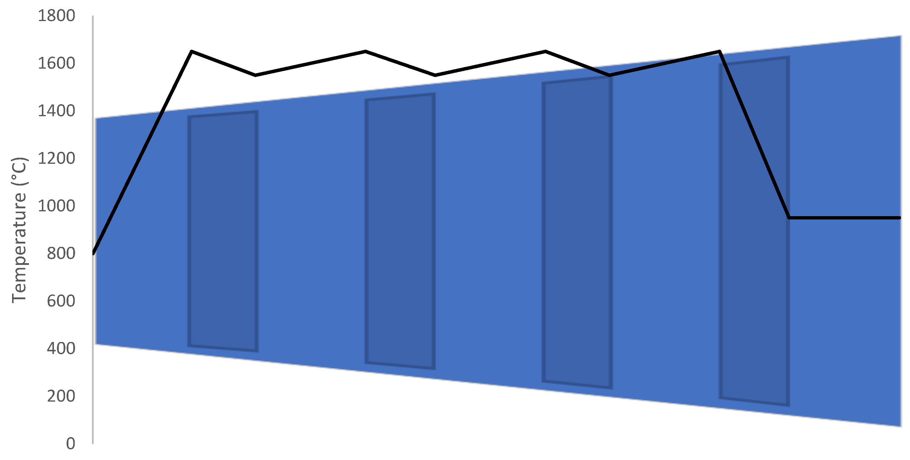
Figure 1. Conceptual outline of the NIHT, showing near-isothermal combustion-expansion in the first three expansion stages followed by an adiabatic expansion in the last stage.
Energies 17 04826 g001
Figure 2. Ericsson cycle and corresponding Temperature (T)—Entropy (s) diagram.
Energies 17 04826 g002
Figure 3. Power cycle configuration including the NIHT.
Energies 17 04826 g003
Figure 4. Schematic of the IRWI power cycle.
Energies 17 04826 g004
Figure 5. Specific total overnight cost for the plants evaluated in this study.
Energies 17 04826 g005
Figure 6. Levelized costs of electricity for the different power cycles without (top) and with (bottom) accounting for the added capital cost involved in delivering a secure supply of fuel and handling the captured CO2. The capacity factor is set to 30% and the CO2 tax to 150 €/ton.
Energies 17 04826 g006
Figure 7. Sensitivity of the economic performance of the different plants to the hydrogen price, excluding pipeline and storage infrastructure. The capacity factor is set to 30% and the CO2 tax to 150 €/ton.
Energies 17 04826 g007
Figure 8. The effect of capacity on the LCOE of the different power cycles without (left) and with (right) accounting for the added capital cost involved in delivering a secure supply of fuel and handling the captured CO2.
Energies 17 04826 g008
Figure 9. The gas turbine cost increase relative to the value calculated using Equation (6) that sets the novel cycle LCOE equivalent to that of a combined cycle (powered by the same fuel) for different capacity factors. The assessment was done without considering fuel supply infrastructure.
Energies 17 04826 g009
Table 1. H-class gas turbine specifications at air intake temperature of 15 °C and 60% relative humidity.
SpecificationValueUnits
Turbine inlet temperature (TIT)1550°C
Pressure ratio23.6-
Filter pressure loss0.75%
Heat losses0.4%LHV
Combustor pressure drop3%
Turbine backpressure3.5kPa
Compressor leakage0.4%
Gas turbine auxiliaries2.2MW
Fuel temperature220°C
Air flow at compressor inlet956.1kg/s
Generator efficiency98.7%
Mechanical efficiency99.865%
Table 2. Calibrated parameters for the H-class gas turbine.
Calibrated ParameterValueUnits
Combustor outlet temperature (COT)1651°C
Turbine outlet temperature (TOT)638.3°C
Gas turbine open cycle net efficiency42.78%
Gas turbine net power513.8MW
Compressor polytropic efficiency92.86%
Expansion stage polytropic efficiency87.58%
Table 3. NIHT and IRWI design parameters.
Design ParameterValueUnits
Recuperator temperature approach (IRWI)40°C
Economizer temperature approach (IRWI)15°C
Intercooler outlet temperature30°C
Maximum air preheat temperature800°C
NIHT HSRG pinch point10°C
Steam coolant temperature350°C
Backpressure steam turbine polytropic efficiency85%
Pump hydraulic efficiency80%
Table 4. Summary of assumed storage and transmission costs [35,36,37].
FuelCavern Storage
($/kWh)
Pipeline Scale
(GW)
Pipeline Cost
(M$/km)
H22.18.361.29
NG0.717.391.57
Table 5. General economic assumptions.
Capital Estimation Methodology
Bare erected cost (BEC)SEA tool or GT correlation
Engineering, procurement, and construction (EPC)10% BEC
Project contingency (PT)20% (BEC+EPC)
Owner’s costs (OC)15% (BEC+EPC+PT)
Total overnight costs (TOC)BEC+EPC+PT+OC
Operating and maintenance costs
Fixed
Maintenance2.6%TOC
Insurance1%TOC
Variable
NG fuel6.5€/GJLHV
H2 fuel13€/GJLHV
CO2 tax150€/ton
Process water6€/ton
Cooling water0.35€/ton
Cash flow analysis assumptions
Discount rate8%
Construction period2Years
Plant Lifetime25Years
Table 6. Technical performance of the power cycles evaluated in the present study.
NGCCNGOCMEA-NGCCH2CCNIHTNIHT+IRWI-NGIRWI-H2
Heat input1201.01201.01201.01180.5832.5850.21504.11546.1MW
Compression441.0441.0441.0433.4179.4182.5443.0454.3MW
Expansion963.5963.5963.5968.1707.1722.91336.41392.7MW
Gas turbine net513.8513.8513.8523.3519.7532.2879.4922.0MW
Steam turbine241.8 179.6232.80.024.80.00.0MW
Auxiliaries−10.0 −41.4−10.3−2.8−3.3−3.0−3.1MW
Net power745.6513.8652.0745.8516.9553.7876.4918.9MW
LHV efficiency62.142.854.363.262.165.158.359.4%
Table 7. Gas turbine specifications for the power cycles evaluated in the present study.
NGCCMEA-NGCCH2CCNIHTNIHT+IRWI-NGIRWI-H2
Air flow956.1956.1963.5365365956.1956.1kg/s
Specific power537.4537.4561.61458.11561.9919.8965.2kJ/kg
Pressure ratio23.623.623.645454545-
Shafts1112222-
Intercooled compressionnononoyesyesyesyes
Disclaimer/Publisher’s Note: The statements, opinions and data contained in all publications are solely those of the individual author(s) and contributor(s) and not of MDPI and/or the editor(s). MDPI and/or the editor(s) disclaim responsibility for any injury to people or property resulting from any ideas, methods, instructions or products referred to in the content.