Abstract
Fuel cell systems often utilize a hydrogen recirculation system to redirect and transport surplus hydrogen back to the anode, which enhances fuel consumption and boosts the efficiency of the fuel cell. Hydrogen recirculation pumps and ejectors are the most investigated systems. Ejectors are gaining recognition as an essential device in fuel cell systems. However, their application in hydrogen recirculation systems is often limited by a narrow operational range. Therefore, it is advantageous to compile the present condition of the study on various ejector shapes as well as configurations that can accommodate a broader operational range, along with the numerical simulations employed in these studies. This paper begins by examining the structure and operation of ejectors. It then compares and analyzes the latest advancements in research on ejector-based hydrogen recirculation systems with extended operating ranges and reviews the details of numerical simulations of ejectors, which are crucial for the development of innovative and efficient ejectors. This study provides key insights and recommendations for integrating hydrogen ejectors into the hydrogen cycle system of fuel cell engines.
1. Introduction
In recent years, fuel cells have garnered significant attention because of their high specific energy density, absence of combustion emissions, and minimal maintenance needs. These characteristics make them particularly suitable for a variety of applications, including vehicles, portable devices, and stationary power generation [1]. Fuel cells transform the chemical energy of a fuel directly into electricity through a pair of redox reactions using an oxidizing agent (usually oxygen), but without combustion. Hydrogen, recognized for its high gravimetric energy density and the fact that its oxidation product is pure water, is emerging as a promising clean energy vector, if produced using renewable energy sources. Fuel cells can be powered directly by hydrogen, making them a completely sustainable energy source when renewable hydrogen is utilized as fuel. As the world increasingly seeks green energy solutions, hydrogen fuel cells are emerging as a promising alternative to traditional fossil-fueled internal combustion engines. The transport sector, dominated by road vehicles, has been identified as a major contributor to global CO2 emissions [2,3]. Therefore, the adoption of hydrogen fuel cells in this sector could play a crucial role in mitigating the impacts of global warming.
Proton Exchange Membrane Fuel Cells (PEMFCs) are a kind of fuel cell that utilizes pure hydrogen as fuel and offer numerous pros like low noise, large specific power, high efficiency, and excellent dynamic characteristics [4,5,6,7]. As such, they hold significant potential in various sectors, including transportation, mobile power stations, and aerospace. As the world aims to reduce emissions, the spread of electric vehicles, especially those powered by fuel cells and batteries, is seen as a viable solution. The automotive industry, in particular, has shown a keen interest in hydrogen PEMFC technology, with leading manufacturers investing heavily in the development of fuel-cell vehicles (FCVs) [8]. Fuel Cell Vehicles (FCVs) based on PEMFC powertrains, such as Toyota Mirai and Hyundai NEXO, the most diffused on the market [9], are a research hotspot due to their zero emissions, high conversion efficiency, and other benefits. These significant technical advancements in sustainable mobility could play a crucial role in slowing the increase in emissions as we transition to low-carbon electricity sources [10,11].
PEMFCs generate electricity and a significant amount of water, necessitating effective management strategies to maintain optimal performance [12]. These strategies include supplying an excess stoichiometric ratio of reaction gas to the PEMFCs and implementing various gas management strategies such as a dead-end anode and exhaust gas recirculation [7,13]. In fuel cell vehicles, hydrogen is stored in high-pressure cylinders. Since PEMFCs operate at near ambient pressure, unreacted hydrogen cannot be reinjected in the storage due to the impracticality of installing a high-pressure hydrogen compressor on a vehicle, and if a recirculation system is not present, it must be released into the environment, strongly reducing the utilization rate and the vehicle efficiency. To address this, researchers have proposed several hydrogen circulation methods, including the use of an ejector or hydrogen recirculation pump [14,15]. The ejector, specifically, offers more practical benefits in fuel cell systems because it consumes less power, operates more quietly, and is more durable than mechanical pumps [16,17,18,19].
The recirculation of hydrogen in PEMFC systems is crucial for several reasons. Firstly, it improves the utilization rate of hydrogen by recirculating the excess hydrogen at the anode outlet back to the anode inlet, allowing it to continue participating in the electrochemical reaction. This not only enhances fuel efficiency but also reduces hydrogen waste [19]. Secondly, recirculation helps in discharging accumulated water and impurity gases at the anode, ensuring the efficient operation of the fuel cell stack. Without effective recirculation, these impurities can lead to anode flooding, which significantly impairs the performance and durability of the fuel cell. Additionally, hydrogen recirculation can increase the gas flow velocity in the anode flow channel, further preventing anode flooding and improving overall system efficiency [20].
In the realm of ejector design and operation, the role of Computational Fluid Dynamic (CFD) simulations and experimental studies is pivotal. The sensitivity of ejectors to geometry and operating conditions necessitates meticulous investigation, as even minor deviations can significantly impair efficiency [21]. CFD simulations, with their extensive applications in fuel cell technology, have proven instrumental in design optimization, performance enhancement, and the resolution of thermal and water management issues. Concurrently, experimental studies offer more accurate and precise results, serving as a benchmark for validating the reliability and predictive capabilities of CFD models. The historical application of CFD in ejector analysis dates back to the early 1900s, with supersonic ejectors used in cooling and refrigeration applications. Over the years, CFD has facilitated a deeper understanding of flow characteristics and has been instrumental in optimizing ejector geometry. Despite the computational intensity and complexity of CFD simulations, their capability to offer detailed insights into flow characteristics underscores their invaluable contribution to ejector analysis. Thus, the synergy of CFD simulations and experimental studies is crucial for advancing ejector technology [22].
Despite the importance of ejectors, their current performance is not yet adequate for practical application due to their narrow operating range and strict operational requirements. However, recent studies have shown promising advancements in developing hydrogen ejectors with a wider operating range. This review uniquely uses bibliometric tools to systematically examine the research condition and improvement trends of ejectors in fuel cell technology. Considering factors like price, material availability, performance, and technological advancement, ejectors are anticipated to become a key area of development in the fuel cell industry. Some automakers are already concentrating on designing and developing ejectors that can operate across the entire power range.
This review begins by detailing the ejector, focusing on its structure and operating principle. Following this, it presents the relevant classification methods and performance indicators. Moreover, various hydrogen recirculation ejectors mentioned in published studies and their configurations are analyzed. In addition, the numerical analyses developed in these studies were scrutinized in terms of turbulence model, grid size, and other relevant criteria to emphasize the importance of numerical analysis and the reliability of the results, along with a comparison with experimental results.
2. Search Strategy, Eligibility Criteria, and Study Selection
A thorough investigation was conducted across Scopus [23] and Web of Science [24] databases to identify research papers using the keywords (ejector), (CFD), (Simulation), and (Fuel cell). The specific search syntaxes are detailed in Table 1. Additionally, a manual search of the bibliographies of selected articles was performed to complement the database search and enrich the research.

Table 1.
Syntax used for search in electronic databases.
The selected articles were chosen from among published peer-reviewed articles, focusing on the numerical modeling of any type of ejector. Publications were excluded if they met any of the following criteria: (1) literature reviews or prospective studies, (2) studies not written in English, and (3) studies that did not include numerical analysis of ejectors. Once the relevant papers were collected and duplicate entries were eliminated, the titles and abstracts of the remaining articles were assessed. Data such as author(s), year of publication, ejector type, nozzle type, power range, dimensions of numerical analysis, turbulence model, and experimental validations were extracted from the included studies.
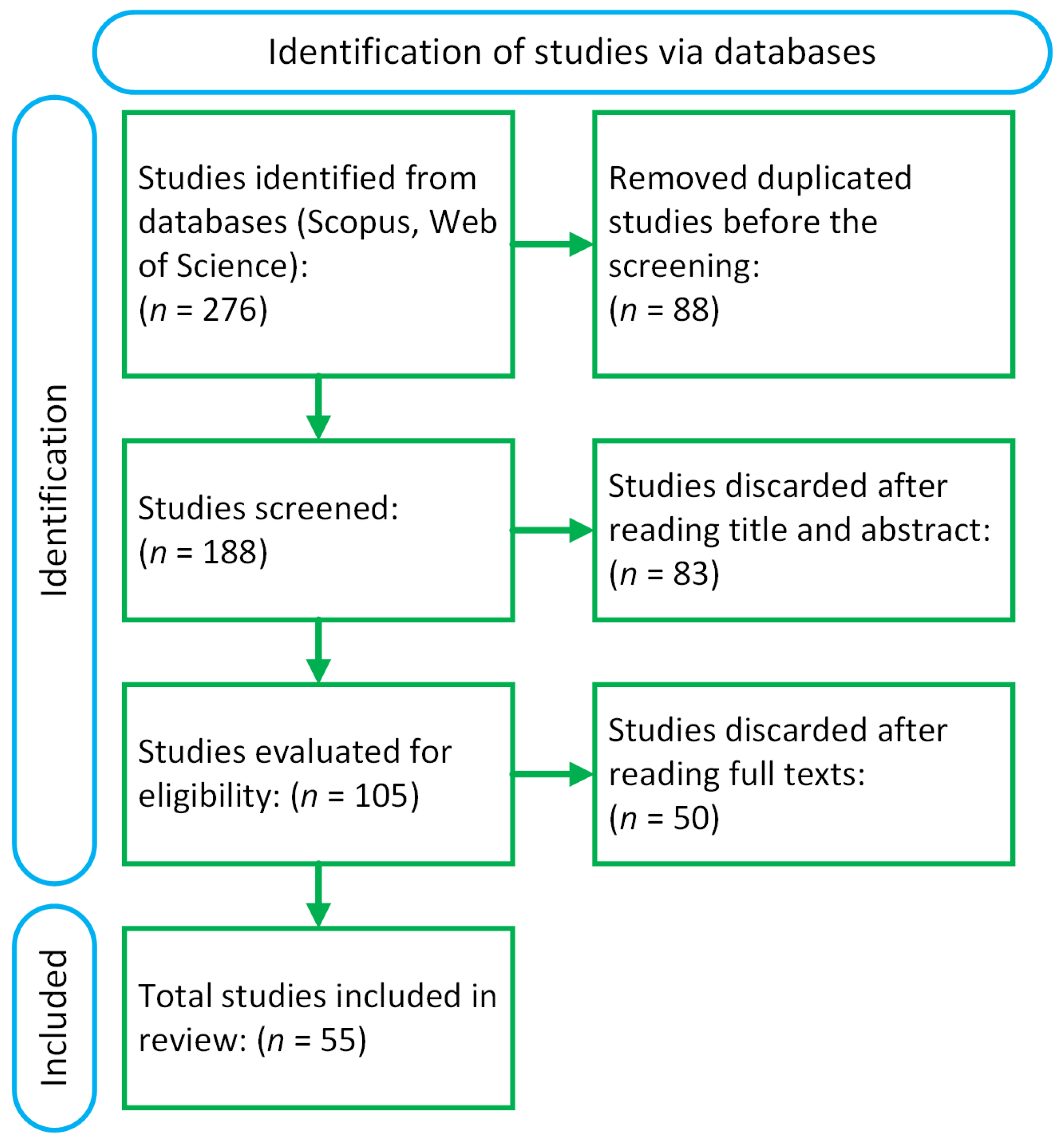
A total of 276 references were found from the database search, with 135 from Scopus and 141 from Web of Science. Once duplicates were removed, 188 studies were left. From these, 83 were eliminated after reviewing their titles and abstracts. After a full-text review, an additional 50 studies were removed because they did not meet the eligibility criteria. In the end, 55 studies that fulfilled the criteria were selected for this systematic review (See Figure 1).
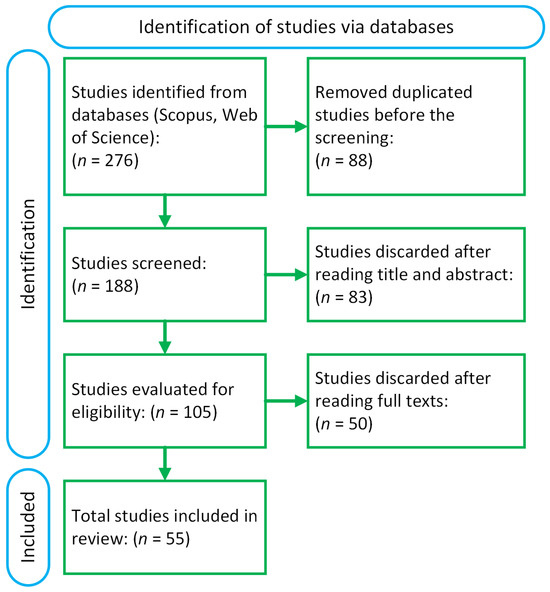
Figure 1.
Flowchart of the literature review and results.
3. Results
3.1. Ejector
3.1.1. Structure
Ejectors have been a research focus in the refrigeration field for several years [25,26]. Recently, many researchers have explored the implementation of ejectors for fuel recirculation purposes in fuel cell systems, primarily PEMFCs. The ejector is a highly efficient device designed to extract gas from a specified container or hose without the need for any moving parts. It operates based on the principle of creating a pressure drop through a high-velocity jet of the working fluid. This jet induces a low-pressure region within the ejector, which in turn facilitates the continuous suction of the ejected gas. The absence of moving parts not only reduces maintenance requirements but also enhances the reliability and longevity of the system. Additionally, the high-speed jet ensures a consistent and stable flow, making the ejector an ideal choice for applications requiring uninterrupted gas extraction.
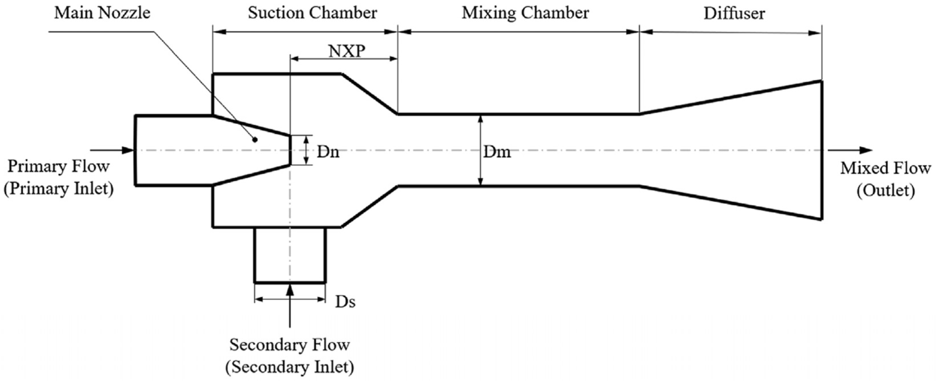
While alternative methods for gas recirculation exist, such as active recirculation pumps, ejectors offer distinct advantages over pumps. These advantages include lower noise levels, compact size, low maintenance costs, no parasitic power consumption, reduced system weight and volume, and a simple structure and design [27,28]. Moreover, ejectors assist in effectively recirculating unreacted hydrogen within the fuel cell system, which minimizes hydrogen consumption and ensures a more consistent fuel supply. This consistent supply helps maintain optimal operating conditions, reducing the stress on the fuel cell components [29,30]. Figure 2 illustrates the geometry of a common ejector, which contains four main components, namely: nozzle, suction chamber, mixing chamber, and diffuser. It also includes some important design parameters, including nozzle diameter (Dn), secondary inlet diameter (Ds), nozzle exit position (NXP), and mixing chamber diameter (Dm). The value of these parameters affects the performance of the ejector [16,31].

Figure 2.
Schematic diagram of an ejector [32].
When the ejector functions within the hydrogen cycle of the fuel cell anode, the primary flow from the hydrogen storage tank experiences a drop in pressure and an increase in velocity as it passes through the nozzle. At the same time, the secondary flow, which is the unreacted hydrogen exiting the stack outlet as a jet flow, is directed into the mixing chamber by the shearing effect of the primary flow. In this chamber, the secondary flow combines with the primary flow, creating what is known as the supply flow. As this combined flow enters the diffusion chamber, its pressure rises. After thorough mixing, it exits the ejector outlet and enters the hydrogen inlet of the fuel cell anode, effectively achieving the goal of pressurized recovery of the circulating fluid [33].
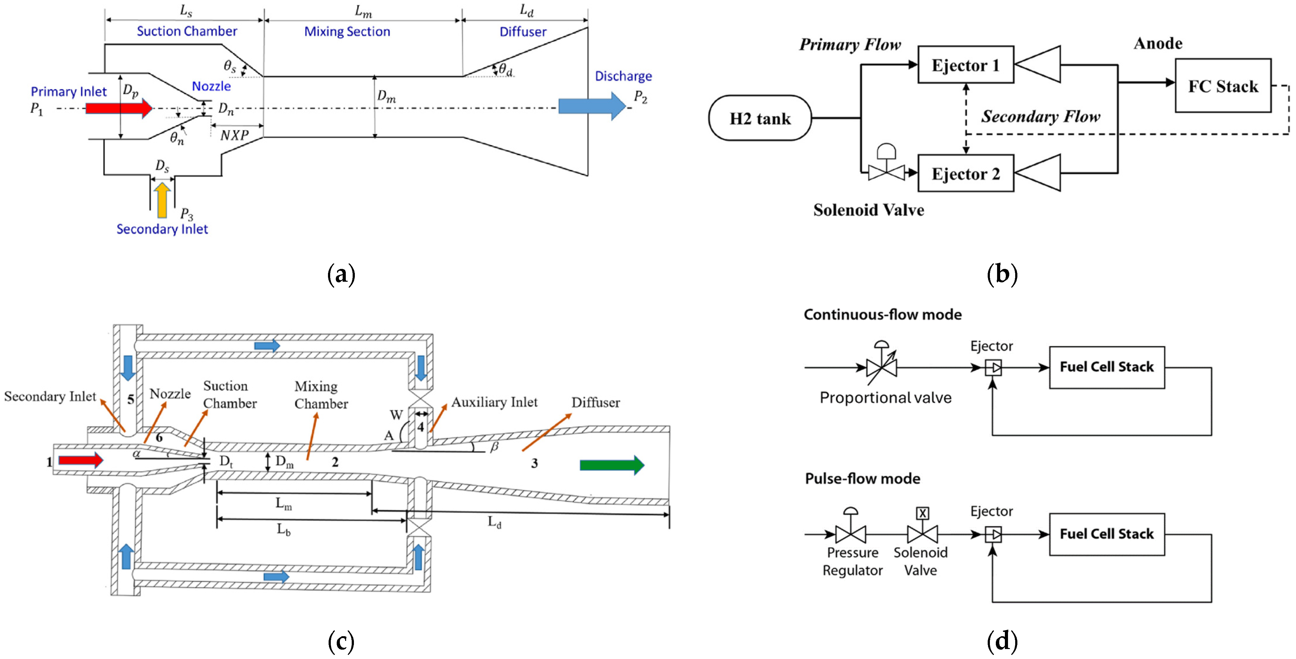
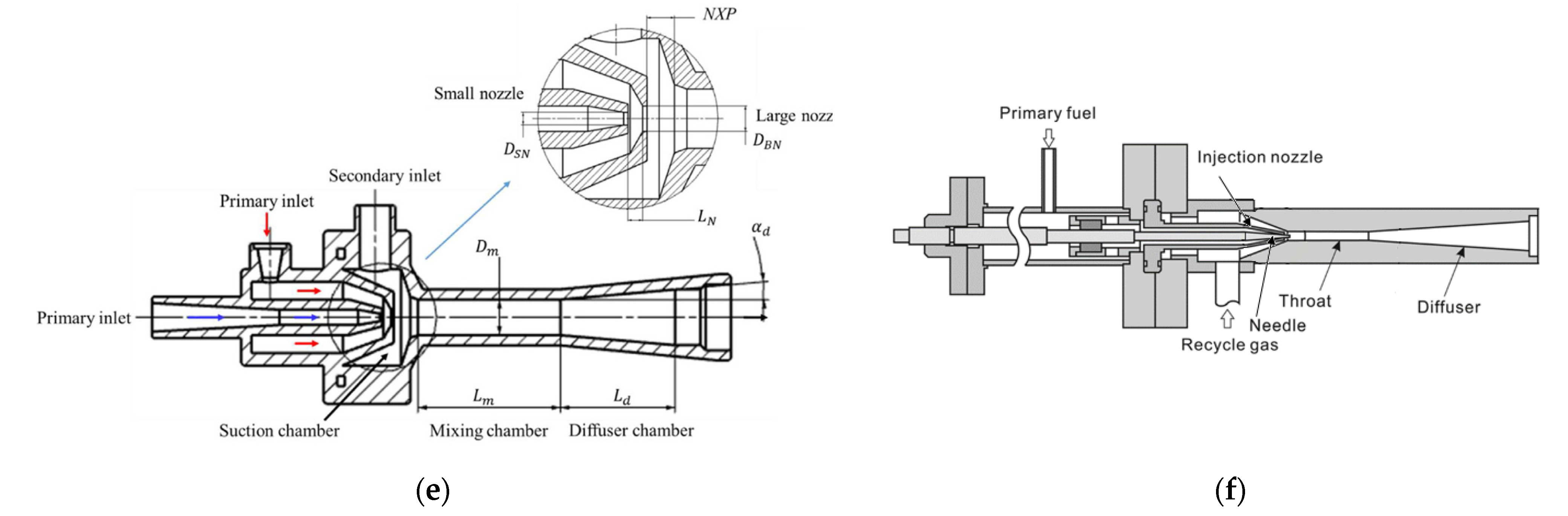
Various ejectors and configurations have been investigated. Ejectors can be categorized, on one hand, into different types, including fixed-geometry (conventional) ejectors, double ejectors, bypass ejectors, pulsed ejectors, multi-nozzle ejectors, and variable ejectors (Figure 3).
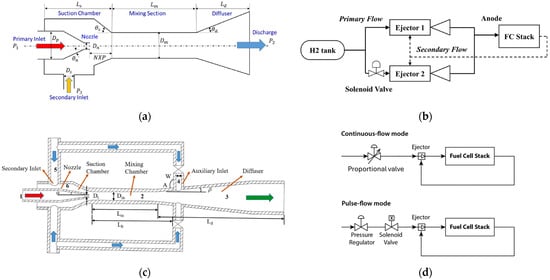
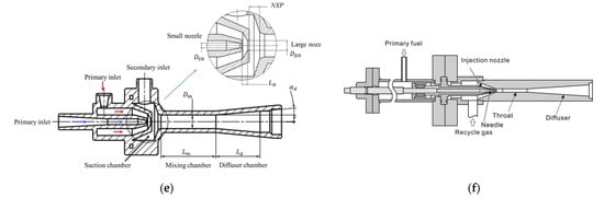
Figure 3.
Various ejector types in the literature: (a) conventional ejector with narrow operation range [34], and wide-operating-range ejector, (b) double ejector [1], (c) bypass ejector [35], (d) pulsed ejector [36], (e) multi-nozzle ejector [37], and (f) variable-geometry ejector (adapted from [38]).
On the other hand, they can be distinguished based on the nozzle shape, which can be either subsonic or supersonic (Figure 4).
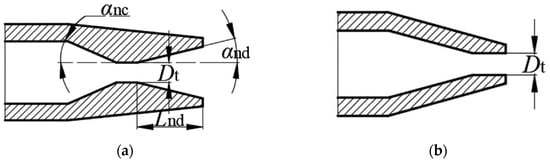
Figure 4.
(a) Supersonic nozzle and (b) subsonic nozzle [39].
3.1.2. Operational States
In an ejector-based system, the entrainment ratio (ω) is a key metric for evaluating ejector performance. This ratio indicates the ability of the primary flow to pass through the nozzle and draw in a secondary flow. Specifically, the entrainment ratio is the ratio of the mass flow rate of the secondary fluid to that of the primary working fluid, as defined by the following equation [40,41,42,43,44]:
where ms and mp denote the secondary and primary mass flow rates, respectively.
In practical scenarios, an ejector might experience two instances of choking. The initial choking happens for the primary flow following the convergent nozzle. After exiting the nozzle, the flow expands within the ejector, leading to the second instance of choking for the secondary flow in the mixing chamber. As a result, the ejector performance can be categorized into three operational states (see Figure 5), which are determined by the ejector discharge or back pressure under constant primary and secondary flow conditions [45].
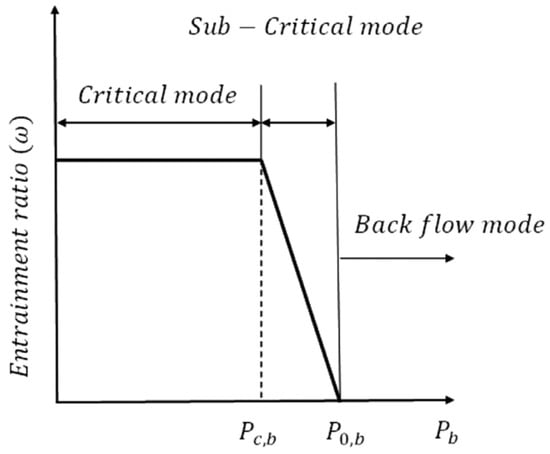
Figure 5.
Common operational states of the ejector [41].
- Critical or dual choking state: This mode is characterized by the discharge pressure being lower than the critical pressure. In this state, the entrainment ratio remains relatively stable, and the ejector operates at its highest efficiency;
- Subcritical or single choking state: In this mode, the discharge pressure (Pc,b < Pb < P0,b) exceeds the critical pressure. As a result, the entrainment ratio experiences a significant reduction as the discharge pressure increases;
- Backflow or malfunction mode: In this mode, Pb > P0,b, the entrainment is reversed, the ejector is not able to work, and no suction occurs.
3.1.3. Various Ejector-Based Hydrogen Recirculation Configuration in Fuel Cell Systems
In the field of PEMFC-based powertrains, FCV manufacturers have selected different solutions for hydrogen management in the anodic loop. For instance, Toyota’s Mirai model employs a single hydrogen recirculation pump, while Hyundai’s NEXO fuel cell vehicle utilizes a unique single-ejector hydrogen recovery scheme. Some vehicles even combine both ejector and pump for hydrogen recirculation in parallel to enhance the efficiency of the fuel cycle system [44].
The use of ejectors in PEMFCs encompasses several areas, including the design and optimization of geometrical features, analyzing the performance characteristics of the PEMFC stack with an ejector, creating ejectors that operate over a wide range, and managing fuel delivery systems. Various configurations for ejector-based hydrogen recirculation were examined to improve ejector performance across a broader operational range, as stated in Table 2.
Table 2.
Summary of characteristics of ejectors and power range condition in reviewed articles.
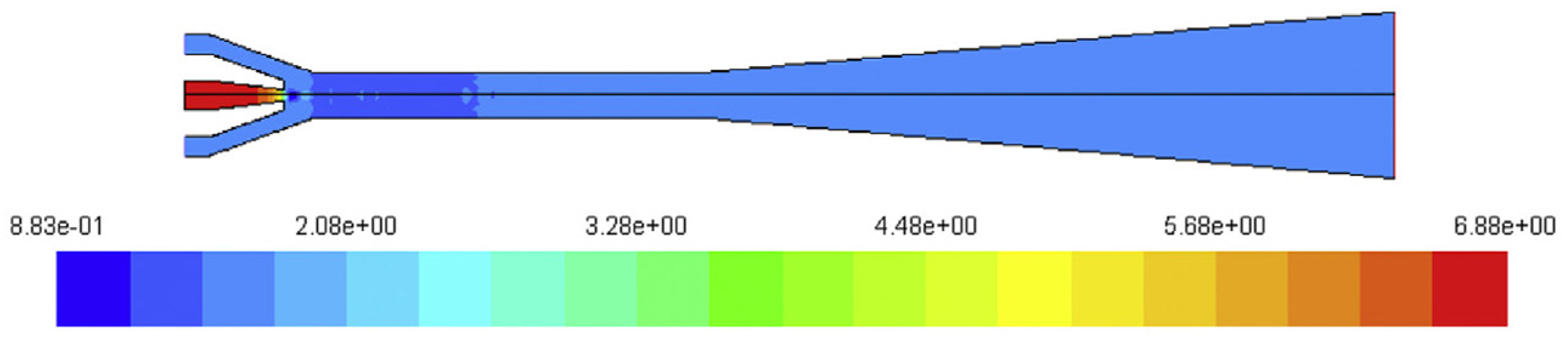
Brunner et al. [50] investigated a variable geometry ejector with a subsonic nozzle, which is controlled by a needle and can be used for a PEMFC with output power from 7 to 17 kW. Their experiments showed that using a variable geometry ejector can significantly influence the entrainment ratio and, ultimately, the performance of the ejector. Hosseinzadeh et al. [41] studied a double ejector with a subsonic nozzle to provide the flow required for a forklift PEMFC. They concluded that the studied configuration can be utilized for a power range from 1.3 to 12.5 kW. They also conducted the same experiments with a variable-geometry ejector and discovered that it is able to operate in a similar mode as the double-ejector configuration. Nonetheless, from a practical point of view, the latter requires a more complex method in order to control the system and is more challenging from a manufacturing point of view. Another important result regarding the fluid dynamics behavior of the ejector was the pressure drop inside the ejector. As illustrated in Figure 6, the primary pressure starts at 6.88 bar and decreases as it passes through the nozzle throat, where the flow transitions into the supersonic regime. This supersonic flow creates a low-pressure region of 0.8 bar, effectively drawing the secondary flow into the ejector. In the mixing chamber, the primary and secondary flows combine, resulting in a pressure recovery of 1.7 bar. As the mixed flow progresses into the diffuser section, the pressure further increases to 1.764 bar.

Figure 6.
Pressure drop profile inside the ejector [41].
Hwang et al. [36] carried out a study on a pulsed ejector using a supersonic nozzle to supply hydrogen for a 1.45 kW PEMFC stack. Their findings demonstrated that hydrogen stoichiometry of the anode could be effectively maintained between 1.4 and 1.6. This was achieved with an entrainment ratio of 40–50% under a steady system power of 1.45 kW.
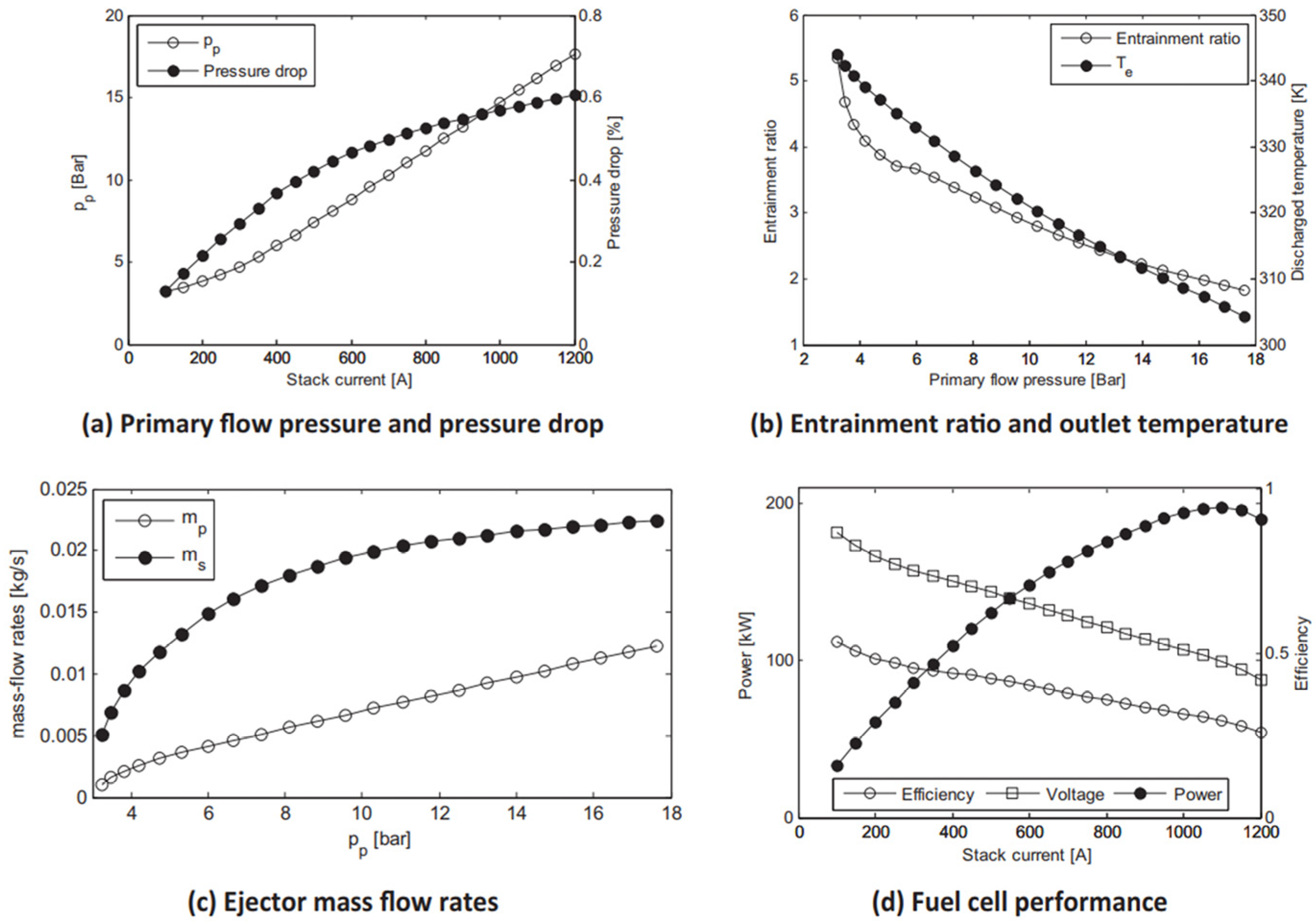
Besagni et al. [54] employed an integrated approach using a CFD model based on lumped parameters to assess the performance of a conventional ejector with a subsonic nozzle required for recirculation of the anode in PEMFC systems. According to their simulation results (Figure 7), they observed that there is a reduction in the efficiency of the fuel cell while the current of the stack rises, which is expected due to polarization effects. On the contrary, there would be an increase in the magnitude of the power of the fuel cell until it arrives at a maximum amount. It is important to note that the studied ejector does not ensure the optimal entrainment ratio for the fuel cell all the time.
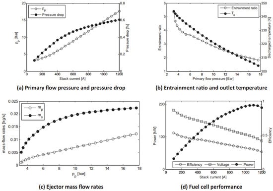
Figure 7.
PEMFC system: simulation results [46].
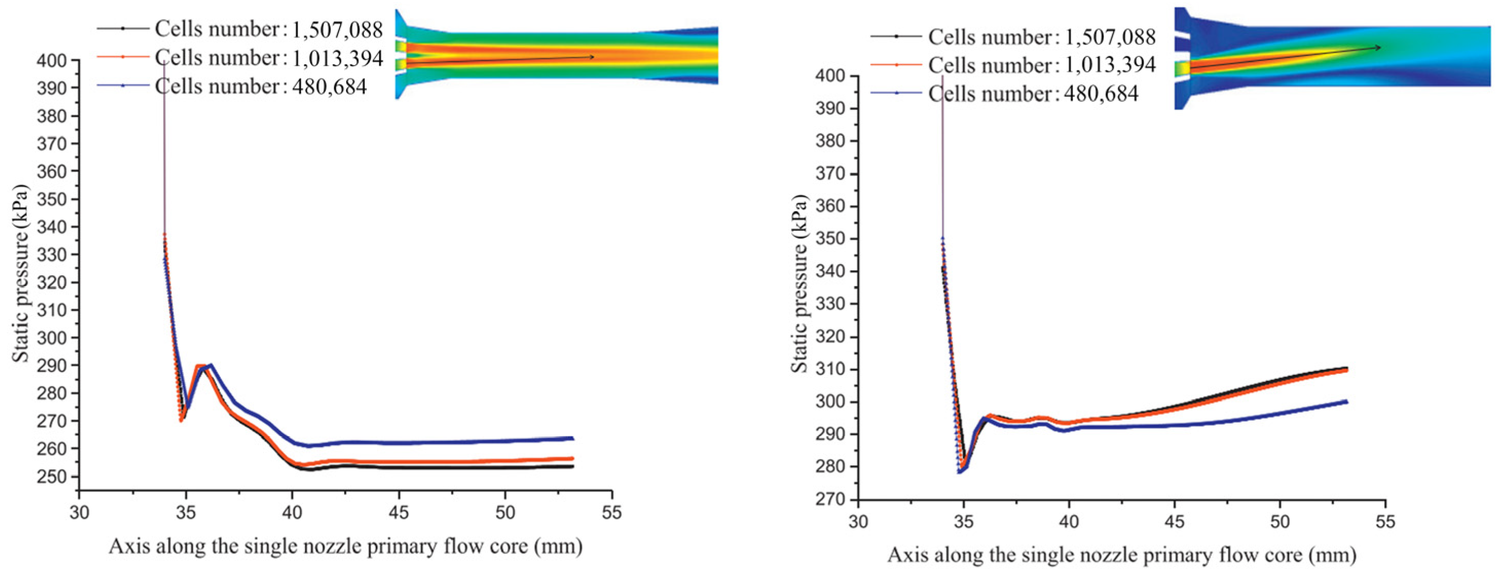
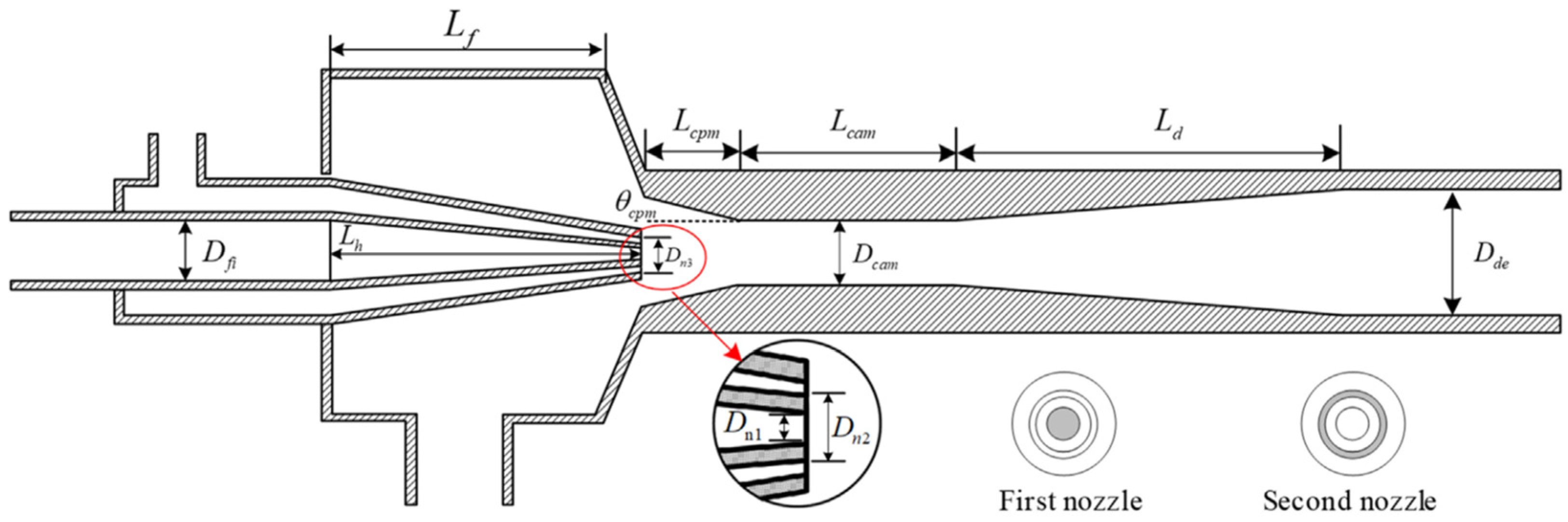
Xue et al. [17] designed, built, and evaluated an innovative multi-nozzle ejector (see Figure 8) capable of covering a broad range of output power from 20 kW to 100 kW, devoid of considerable differences in the magnitude of pressure at the primary inlet, simply by changing the nozzle operation modes. It was observed that when the nozzles are open and work simultaneously, some issues like vortices would be efficiently managed. Furthermore, the two-nozzle operation mode is able to obtain the greatest recirculation capacity. They also analyzed the magnitude of pressure drop in two different operation modes along the ejector. As can be seen in Figure 9, the pressure dramatically drops in both cases, and then, after combining with secondary flow, the pressure rises.
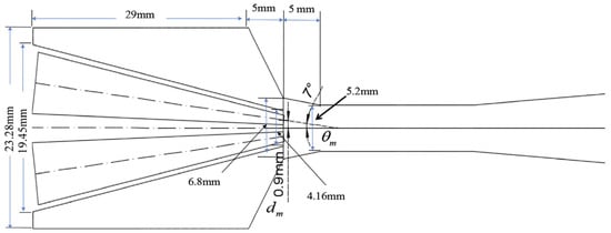
Figure 8.
Multi-nozzle ejector studied in [17].
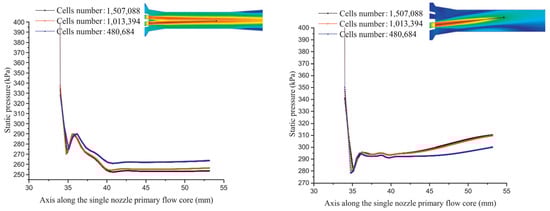
Figure 9.
Pressure drop magnitude along the ejector [17].
Another multi-nozzle ejector, a so-called coaxial-nozzle ejector, has been designed and analyzed by Du et al. [61], which can meet the needs of the PEMFC system across various power output ranges (Figure 10). The results indicated that the examined ejector could function effectively within a broad power range of 17.90–84 kW, provided there is an adequate hydrogen supply at pressures between 4 and 7 bar. Additionally, the ejector maintains a recirculation ratio above 0.9 across the entire power range and achieves a high recirculation ratio exceeding 2.0 at lower power outputs.

Figure 10.
Multi-nozzle (coaxial-nozzle) ejector studied in [61].
Han et al. [62] studied a multi-nozzle ejector that includes one central nozzle (CN) and two symmetrical nozzles (SNs). The CN condition is utilized when low power is required, while the SNs condition is activated for high power conditions. Their findings revealed that the multi-nozzle ejector can operate within a range of 0.27 to 1.6 g/s (22–100 kW).
Chen et al. [34] assessed the performance of a double ejector configuration for PEMFC in order to cover a wide operational range from 5.6 kW to 70 kW. They found that the ideal geometric configuration allowed each ejector to support a particular range of power while increasing entrainment efficiency. Additionally, by optimally controlling the flow of hydrogen and timing the opening and closing of the two ejectors, they diminished variations in the pressure of the anode gas, thereby decreasing potential damage to the PEMFC’s operational lifespan. Yu et al. [35] investigated a bypass-based ejector in order to widen the operating range of PEMFCs. They have found that the performance of the ejector is highly sensitive to the position, width, and angle of the bypass port. The performance of the proposed ejector seemed to be satisfactory while covering the output power of 17.9 to 84 kW.
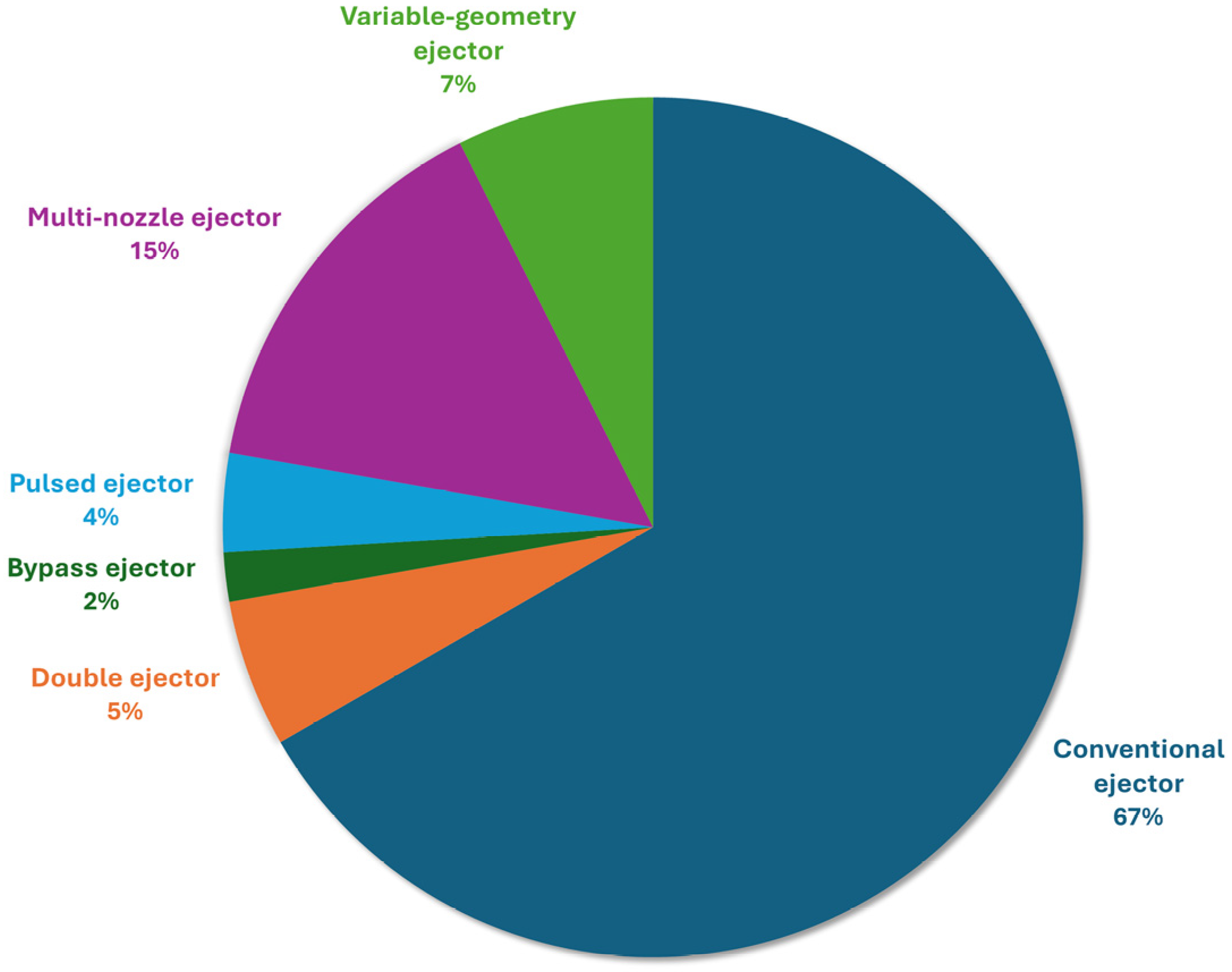
The distribution of ejector types and configurations examined in the surveyed literature is presented in Figure 11. Conventional ejectors, accounting for 67% of the studies, are the predominant method for hydrogen recirculation. The multi-nozzle ejector, despite only representing 15% of the studies, is noteworthy. This is particularly significant considering that the first study on multi-nozzle ejectors, within the scope of the reviewed articles, was published by Xue et al. in 2020 [17]. Subsequently, an increasing number of research groups have focused their efforts on multi-nozzle ejectors, leading to the development of a variety of geometries [37,50,61,62].
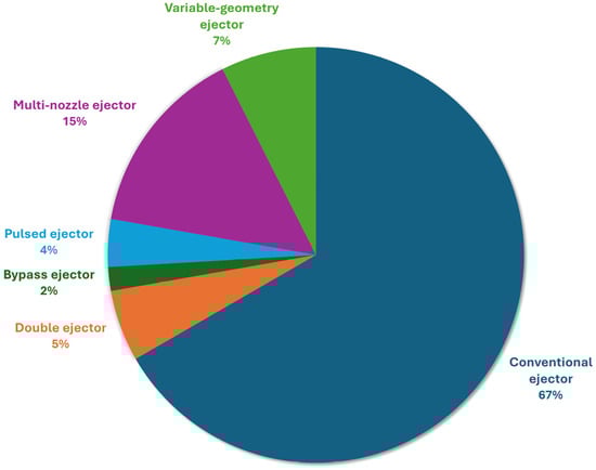
Figure 11.
Distribution of different ejector types and configurations examined in the reviewed articles.
As previously stated, a primary concern with conventional ejectors was their inability to adapt to a broader power range. Consequently, alternative configurations were introduced to encompass a larger output power range. Figure 12 illustrates the power range that some of the proposed ejector-based hydrogen recirculation methods, as discussed in the literature, can cover.
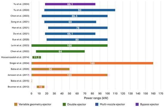
Figure 12.
Power range covered by each ejector-based hydrogen recirculation configuration in the literature [17,19,21,34,35,37,38,41,50,58,61,62,64,81,82].
3.2. Numerical Modeling
Numerical modeling, particularly CFD, is recognized as a consistent approach for modeling fluid flow within ejectors [45,63]. It accurately captures a wide range of flow phenomena such as shock waves, mixing, boundary layer, phase change, compressibility, supersonic flow, and complex flow. This tool has been instrumental in researchers gaining a more profound knowledge of the hydrodynamic performance of ejectors, thereby leading to enhanced designs as well as optimization. However, the complexity and computational intensity of CFD simulations make them more resource-demanding compared to analytical models, which can pose challenges in scenarios with limited computational resources. Additionally, selecting a suitable physical model, especially for turbulence, is of paramount importance [65]. Furthermore, the proper handling of numerical settings and discretization schemes is crucial for achieving a stable and converged solution, emphasizing the precision required in CFD studies.
The mesh quality is a pivotal factor that demands careful consideration. This is particularly true in scenarios where shock waves, boundary layers, and mixing processes significantly influence the performance of the simulation [41]. To accurately capture these local flow features, it is essential to refine the mesh in these critical regions. However, this is not a straightforward task. Researchers often find themselves experimenting with various mesh qualities, observing the changes in results as the mesh size varies. The objective of this iterative process is to identify a mesh that yields what can be considered mesh-independent results. This step is of paramount importance, as denser meshes, while potentially offering more precise results, also lead to a substantial increase in computation time [1]. This can render the simulation prohibitively expensive and, in some instances, beyond the reach of the available resources. Therefore, striking a balance between accuracy and computational efficiency is a key challenge in CFD simulations. Among the reviewed articles, 36 studies mentioned the number of grids (19 with 2D axisymmetric simulation and 17 with 3D simulation), with some also specifying the type of grid. Kuo et al. [44] reported the lowest density grid, demonstrating that a 25,058-cell grid strikes a trade-off between model accuracy and cost. Conversely, Huang et al. [68] investigated ejector performance using a grid of around 500,000 cells, employing the entrainment ratio as a criterion for mesh independence. Overall, 160,000 cells have been proven to be sufficient to carry out a 2D axisymmetric simulation considering the mesh independence analysis (See Table 3). Moreover, the 3D simulation conducted by Kuo et al. [77] could gain convergence with a 436 million mesh, which is the most intense mesh applied for 3D simulation of ejector performance among the reviewed articles. However, other studies demonstrated the convergence of their results with 213,264 [39], 387,974 [62], and 400,000 [58].
Table 3.
Summary of CFD analysis in reviewed articles.
Numerical setup is a critical aspect of CFD simulations. Generally, CFD simulations fall into two main categories: density-based and pressure-based solvers. Supersonic flows, characterized by shock waves, typically demand the use of density-based solvers to accurately capture the flow behavior. Conversely, pressure-based solvers are commonly employed for simulating low-speed, incompressible flows. Selecting the appropriate solver type is essential for ensuring accurate and reliable results in CFD simulations tailored to the specific characteristics of the flow under investigation.
In CFD simulations, the Reynolds-Averaged Navier–Stokes (RANS) equations are of importance. The RANS method is a numerical technique that models turbulent flow by disintegrating flow quantities into their time-averaged and fluctuating components, a process known as Reynolds decomposition. This decomposition leads to the derivation of the RANS equations, which are time-averaged equations of motion for fluid flow. The averaging of the Navier–Stokes equations results in a nonlinear Reynolds stress term that necessitates additional modeling to fully resolve the system. This is where turbulence models come into play. They provide a means to close the system of equations by modeling the Reynolds stresses that appear in the RANS equations due to the averaging process. A variety of turbulence models are typically employed in the context of the RANS equations, including k-ε based models (Standard, Realizable, and Re-Normalization Group (RNG)), k-ω based models (Standard and Shear Stress Transport (SST)), and the Reynolds Stress Model (RSM). The Large Eddy Simulation (LES) model, on the other hand, is a different approach that resolves large energy-containing scales of the flow and models the smaller scales. The turbulence transport equations are given below.
Standard k-ε transport equation:
RNG k-ε transport equation:
Realizable k-ε transport equation:
Standard k-ω Transport equation:
SST k-ω Transport equation:
The k-ε and k-ω models necessitate the solution of two equations to assess turbulence kinetic energy (k) and dissipation rates (ε and ω). They rely on the Boussinesq approximation method, as depicted in Equation (7), to determine the turbulent viscosity (µt), which is appropriate in terms of cost of computation, rendering them broadly adopted. Nevertheless, they are limited by the assumption of isentropic scalar turbulent viscosity. Nonetheless, this assumption does not significantly impact ejector modeling, as it functions effectively for jets, mixing layers, and boundary layers [32]. The LES technique calculates flow details through spatial averaging rather than time averaging, thereby retaining the evolving traits of turbulent structures crucial for fluid entrainment and mixing within ejectors. It adeptly tackles the shortcomings of RANS methods, demonstrating significant promise in representing turbulent behavior in supersonic jet contexts [81]. RSM needs advanced computational resources, hence the use of more governing equations. The additional computational burden is only warranted in scenarios where the anisotropy of turbulence, such as swirling, has a significant impact. However, this is typically not the case for the flow within an ejector, especially for 2D axisymmetric domains where transverse effects are disregarded [32].
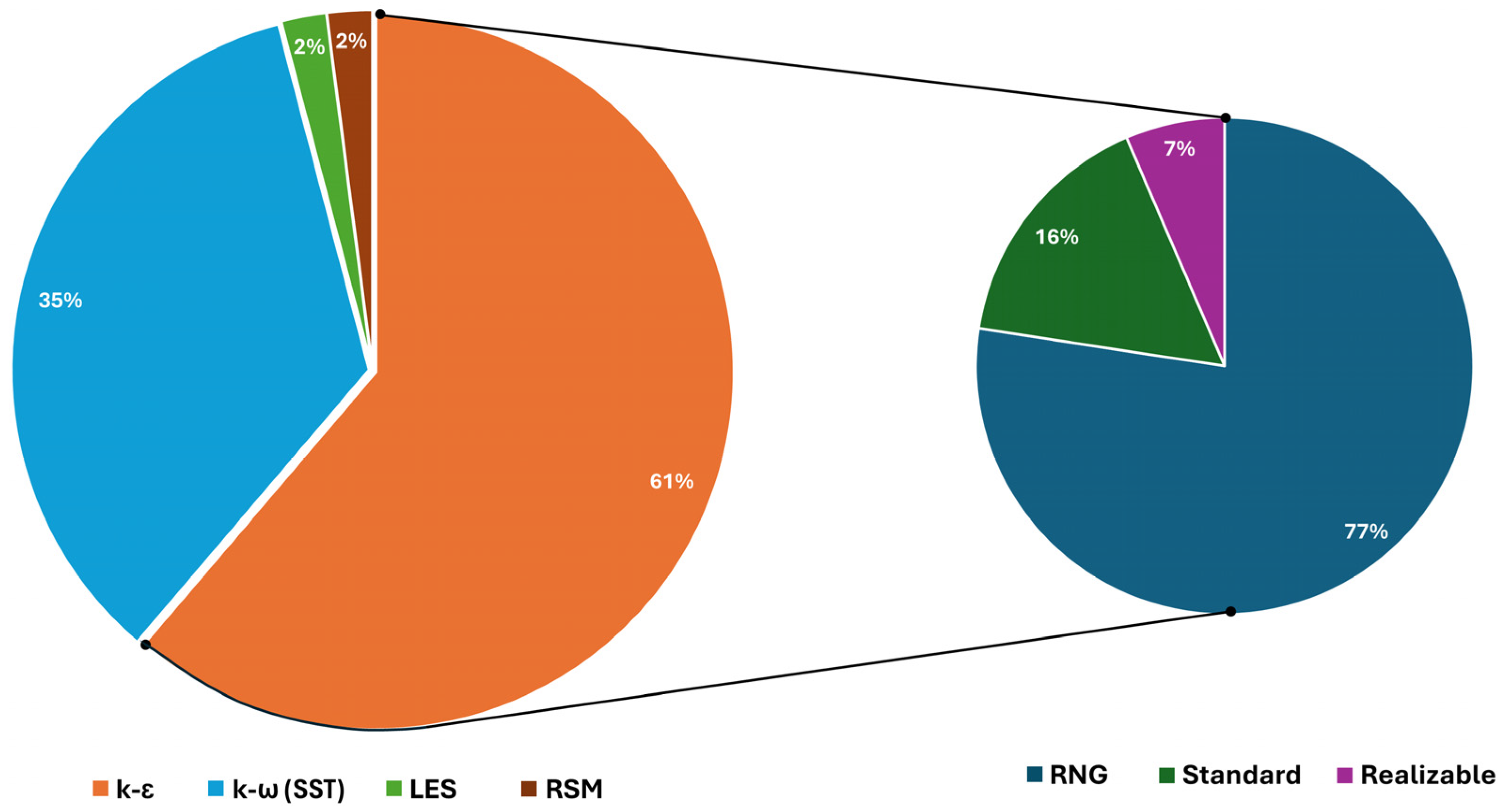
When considering overall operational factors such as flow rates and entrainment ratio, both k-ε and k-ω models have proven effective, enhancing the utility of CFD simulation for predicting and exploring these parameters. However, discrepancies may arise in predicting local flow characteristics when comparing results from different turbulence models. These local features encompass shock wave structures, velocity, and pressure profiles, as well as contours, with conflicting preferences evident across various literature sources. According to Figure 13, k-ε (RNG) was the most utilized turbulence model among the reviewed articles (See Table 3), and only 35% of studies used the k-ω (SST).
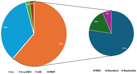
Figure 13.
Distribution of different turbulence models in reviewed articles.
Nikiforow et al. [52] utilized k-ω (SST) and k-ε (RNG and Realizable) turbulence models to analyze ejector efficiency. They found that the results based on the k-ω (SST) model were more accurate and aligned with their experimental results. Furthermore, they suggested that the k-ω (SST) is appropriate to predict the performance of the ejector, whereas, for optimization purposes, the k-ε models can be considered. Chen et al. [60] evaluated various turbulence models and found that the k-ε (Standard) model is more accurate for lower flow rates compared to other models. Additionally, at higher flow rates, the k-ε (Realizable) model performed better with more accuracy compared with other models. Singer et al. [21] compared different turbulence models to validate the performance of an ejector in a PEMFC. They identified the RSM as the optimal turbulence model, as it could achieve a variation of 6.1% in the entrainment ratio comparing the experimental results and those of simulations, which was significantly lower compared to that of traditional models.
4. Limitations and Future Directions
This study acknowledges several limitations. Firstly, the availability of publications is limited, which constrains the breadth of the analysis. Single samples can significantly influence the overall results, potentially skewing the findings. Although ejector design has a long history, its application in fuel cell hydrogen cycle systems is relatively recent, which may bias the analysis. Additionally, this study lacks a cost market analysis related to the ejector, focusing instead on methodological improvement and analysis. The publications analyzed are sourced from Scopus and Web of Science, excluding non-scientific bases, and only English publications were considered, potentially omitting relevant studies in other languages. The review is confined to various ejector shapes and configurations, along with numerical analysis, leading to certain research limitations.
Future research should expand the review’s scope to improve bibliometric analysis accuracy and capture industry development trends. Incorporating innovative methodologies, such as AI applied to big data analytics, sophisticated computer-based algorithms, developing databases, and enhancing graphic-based methodologies, could significantly advance the field. Specific research areas to focus on include optimizing ejector design by investigating new materials and configurations, studying the integration of ejectors with PEMFC systems to enhance overall performance, conducting detailed cost-benefit analyses to improve economic viability, assessing the environmental impact of ejectors in hydrogen recirculation systems, and performing extensive experimental studies to validate numerical models and simulations. This comprehensive approach will help address current limitations and pave the way for future advancements in fuel cell technology.
5. Conclusions
A review of global research patterns indicates that ejector research is experiencing a period of swift growth, with an annual increase in the number of publications in recent years. The emergence of keywords such as “ejector”, “hydrogen recirculation”, and “fuel recirculation” suggests that the use of ejectors for hydrogen recirculation purposes has become a trending research subject lately. This paper offers an overview of ejectors and a review of the progress in research. Initially, the study outlines the structure, operational principle, classifications, and pertinent performance metrics of ejectors. Subsequently, it provides a comprehensive review and synthesis of different ejector shapes and configurations with the aim of wide operating range coverage, as well as the specifications of numerical analysis employed in the studies simulating the ejector performance. Despite extensive research conducted by scholars on ejectors, there is a need for additional work to address existing knowledge gaps, including the following:
- More precise numerical simulations should be performed in order to state the significance of pressure drops across various ejector designs, highlighting the impact of shape and configuration on performance;
- Although some studies consider various ejector shapes and configurations to cover a wide operating range, including multi-nozzle and double ejector designs, further research is required to optimize these designs;
- More detailed and sophisticated numerical analysis should be considered to better mimic the ejector’s performance and decrease the limitations of simulation. This can be achieved by employing more advanced turbulence models together with 3D simulations.
Author Contributions
Conceptualization, M.A. and M.M.; methodology, M.A. and M.M.; formal analysis, M.A. and M.M.; investigation, M.A.; resources, M.A.; data curation, M.A.; writing—original draft preparation, M.A.; writing—review and editing, M.M. and D.F.; visualization, M.A.; supervision, M.S.; project administration, M.S., D.F., and M.M.; funding acquisition, M.S. and D.F. All authors have read and agreed to the published version of the manuscript.
Funding
The work for this publication is part of the project NODES, which has received funding from the MUR—M4C2 1.5 of PNRR funded by the European Union—NextGenerationEU (Grant agreement no. ECS00000036).
Data Availability Statement
Data are contained within the paper.
Acknowledgments
The authors would like to acknowledge the support of Raicam Driveline S.r.l. for the development of this review manuscript.
Conflicts of Interest
The authors declare no conflicts of interest.
References
- Liu, Y.; Tu, Z.; Chan, S.H. Applications of ejectors in proton exchange membrane fuel cells: A review. Fuel Process. Technol. 2021, 214, 106683. [Google Scholar] [CrossRef]
- Wu, S.; Liu, Z.; Du, J.; Liu, Y. Change of global ocean temperature and decadal variability under 1.5 °C warming in FOAM. J. Mar. Sci. Eng. 2022, 10, 1231. [Google Scholar] [CrossRef]
- Gu, L.; Chen, J.; Yin, J.; Slater, L.J.; Wang, H.M.; Guo, Q.; Feng, M.; Qin, H.; Zhao, T. Global increases in compound flood-hot extreme hazards under climate warming. Geophys. Res. Lett. 2022, 49, e2022GL097726. [Google Scholar] [CrossRef]
- Lü, X.; Qu, Y.; Wang, Y.; Qin, C.; Liu, G. A comprehensive review on hybrid power system for PEMFC-HEV: Issues and strategies. Energy Convers. Manag. 2018, 171, 1273–1291. [Google Scholar] [CrossRef]
- Peighambardoust, S.J.; Rowshanzamir, S.; Amjadi, M. Review of the proton exchange membranes for fuel cell applications. Int. J. Hydrogen Energy 2010, 35, 9349–9384. [Google Scholar] [CrossRef]
- Başar, M.S.; Çağlayan, B.S.; Aksoylu, A.E. A study on catalytic hydrogen production: Thermodynamic and experimental analysis of serial OSR-PROX system. Fuel Process. Technol. 2018, 178, 301–311. [Google Scholar] [CrossRef]
- Wang, X.; Qin, Y.; Wu, S.; Shangguan, X.; Zhang, J.; Yin, Y. Numerical and experimental investigation of baffle plate arrangement on proton exchange membrane fuel cell performance. J. Power Sources 2020, 457, 228034. [Google Scholar] [CrossRef]
- Walters, M.; Wick, M.; Tinz, S.; Ogrzewalla, J.; Sehr, A.; Pischinger, S. Fuel Cell System Development. SAE Int. J. Altern. Powertrains 2018, 7, 335–350. [Google Scholar] [CrossRef]
- Hassan, Q.; Azzawi, I.D.; Sameen, A.Z.; Salman, H.M. Hydrogen fuel cell vehicles: Opportunities and challenges. Sustainability 2023, 15, 11501. [Google Scholar] [CrossRef]
- Fragiacomo, P.; Genovese, M.; Piraino, F.; Corigliano, O.; De Lorenzo, G. Hydrogen-fuel cell hybrid powertrain: Conceptual layouts and current applications. Machines 2022, 10, 1121. [Google Scholar] [CrossRef]
- Bethoux, O. Hydrogen fuel cell road vehicles and their infrastructure: An option towards an environmentally friendly energy transition. Energies 2020, 13, 6132. [Google Scholar] [CrossRef]
- Shen, J.; Liu, Z.; Liu, F.; Liu, W. Numerical simulation of water transport in a proton exchange membrane fuel cell flow channel. Energies 2018, 11, 1770. [Google Scholar] [CrossRef]
- Song, Y.; Zhang, C.; Jia, Q.; Birgersson, E.; Han, M.; Zhang, P. Novel closed anode pressure-swing system for proton exchange membrane fuel cells. Int. J. Hydrogen Energy 2020, 45, 17727–17735. [Google Scholar] [CrossRef]
- Liu, J.; Li, Q.; Chen, W.; Cao, T. A discrete hidden Markov model fault diagnosis strategy based on K-means clustering dedicated to PEM fuel cell systems of tramways. Int. J. Hydrogen Energy 2018, 43, 12428–12441. [Google Scholar] [CrossRef]
- Liu, Z.; Liu, Z.; Jiao, K.; Yang, Z.; Zhou, X.; Du, Q. Numerical investigation of ejector transient characteristics for a 130-kW PEMFC system. Int. J. Energy Res. 2020, 44, 3697–3710. [Google Scholar] [CrossRef]
- Maghsoodi, A.; Afshari, E.; Ahmadikia, H. Optimization of geometric parameters for design a high-performance ejector in the proton exchange membrane fuel cell system using artificial neural network and genetic algorithm. Appl. Therm. Eng. 2014, 71, 410–418. [Google Scholar] [CrossRef]
- Xue, H.; Wang, L.; Zhang, H.; Jia, L.; Ren, J. Design and investigation of multi-nozzle ejector for PEMFC hydrogen recirculation. Int. J. Hydrogen Energy 2020, 45, 14500–14516. [Google Scholar] [CrossRef]
- Zhang, X.; Wang, L.; Zhang, H.; Jia, L. Optimization of ejector structure for the PEMFC hydrogen recirculation system. In Proceedings of the 2020 Chinese Automation Congress (CAC), Shanghai, China, 6–8 November 2020; pp. 2954–2959. [Google Scholar]
- Jenssen, D.; Berger, O.; Krewer, U. Improved PEM fuel cell system operation with cascaded stack and ejector-based recirculation. Appl. Energy 2017, 195, 324–333. [Google Scholar] [CrossRef]
- Liu, Y.; Tu, Z.; Chan, S.H. Performance analysis and dynamic characteristics of a proton exchange membrane fuel cell with dual recirculation pumps for air-free applications. J. Power Sources 2023, 566, 232926. [Google Scholar] [CrossRef]
- Singer, G.; Pinsker, R.; Stelzer, M.; Aggarwal, M.; Pertl, P.; Trattner, A. Ejector validation in proton exchange membrane fuel cells: A comparison of turbulence models in computational fluid dynamics (CFD) with experiment. Int. J. Hydrogen Energy 2024, 61, 1405–1416. [Google Scholar] [CrossRef]
- Little, A.B.; Garimella, S. A review of ejector technology for refrigeration applications. Int. J. Air-Cond. Refrig. 2011, 19, 1–15. [Google Scholar] [CrossRef]
- Scopus. Available online: https://www.scopus.com/ (accessed on 17 August 2024).
- Web of Science. Available online: https://www.webofscience.com/ (accessed on 17 August 2024).
- Gil, B.; Kasperski, J. Performance estimation of ejector cycles using ethers and fluorinated ethers as refrigerants. Appl. Therm. Eng. 2018, 133, 269–275. [Google Scholar] [CrossRef]
- Rusly, E.; Aye, L.; Charters, W.; Ooi, A. CFD analysis of ejector in a combined ejector cooling system. Int. J. Refrig. 2005, 28, 1092–1101. [Google Scholar] [CrossRef]
- Li, M.; Lin, M.; Wang, L.; Wang, Y.; Pan, F.; Zhao, X. Observation and Analysis of Ejector Hysteresis Phenomena in the Hydrogen Recirculation Subsystem of PEMFCs. Entropy 2023, 25, 426. [Google Scholar] [CrossRef]
- Li, K.; Wang, C.; Li, J.; Wang, L.; Li, Z.; Zhang, C. Experimental Investigation into the Performance of PEMFCs with Three Different Hydrogen Recirculation Schemes. Inventions 2024, 9, 33. [Google Scholar] [CrossRef]
- Tang, X.; Yang, M.; Shi, L.; Hou, Z.; Xu, S.; Sun, C. Adaptive state-of-health temperature sensitivity characteristics for durability improvement of PEM fuel cells. Chem. Eng. J. 2024, 491, 151951. [Google Scholar] [CrossRef]
- Tang, X.; Shi, L.; Zhang, Y.; Li, B.; Xu, S.; Song, Z. Degradation adaptive energy management strategy for FCHEV based on the Rule-DDPG method: Tailored to the current SOH of the powertrain. In IEEE Transactions on Transportation Electrification; IEEE: Piscataway, NJ, USA, 2024. [Google Scholar]
- Bai, S.; Wang, L.; Wang, X. Optimization of ejector geometric parameters with hybrid artificial fish swarm algorithm for PEM fuel cell. In Proceedings of the 2017 Chinese Automation Congress (CAC), Jinan, China, 20–22 October 2017; pp. 3319–3322. [Google Scholar]
- Ma, T.; Cong, M.; Meng, Y.; Wang, K.; Zhu, D.; Yang, Y. Numerical studies on ejector in proton exchange membrane fuel cell system with anodic gas state parameters as design boundary. Int. J. Hydrogen Energy 2021, 46, 38841–38853. [Google Scholar] [CrossRef]
- Le Tri, D.T.; Vu, H.N.; Woo, J.; Kim, Y.; Yu, S. Optimization of the ejector parameters for anodic recirculation systems in high-performance dual-stack proton-exchange membrane fuel cells. Energy Convers. Manag. 2023, 296, 117712. [Google Scholar] [CrossRef]
- Chen, L.; Xu, K.; Yang, Z.; Yan, Z.; Dong, Z. Optimal design and operation of dual-ejector PEMFC hydrogen supply and circulation system. Energies 2022, 15, 5427. [Google Scholar] [CrossRef]
- Yu, M.; Wang, C.; Wang, L.; Wang, X.; Li, D. Auxiliary-ejector-based hydrogen recirculation system to broaden PEMFC operating range. Int. J. Hydrogen Energy 2024, 57, 515–529. [Google Scholar] [CrossRef]
- Hwang, J.-J. Passive hydrogen recovery schemes using a vacuum ejector in a proton exchange membrane fuel cell system. J. Power Sources 2014, 247, 256–263. [Google Scholar] [CrossRef]
- Chen, L.; Xu, K.; Yang, Z.; Yan, Z.; Zhai, C.; Dong, Z. Optimal design of a novel nested-nozzle ejector for PEMFC’s hydrogen supply and recirculation system. Int. J. Hydrogen Energy 2023, 48, 27330–27343. [Google Scholar] [CrossRef]
- Baba, S.; Kobayashi, N.; Takahashi, S.; Hirano, S. Development of anode gas recycle system using ejector for 1 kW solid oxide fuel cell. J. Eng. Gas Turbine. Power 2015, 137, 021504. [Google Scholar] [CrossRef]
- Feng, J.; Han, J.; Hou, T.; Peng, X. Performance analysis and parametric studies on the primary nozzle of ejectors in proton exchange membrane fuel cell systems. In Energy Sources, Part A: Recovery, Utilization, and Environmental Effects; Taylor & Francis: Abingdon, UK, 2020; pp. 1–20. [Google Scholar]
- Han, J.; Zhao, B.; Pang, Z.; Feng, J.; Peng, X. Transient characteristics investigation of the integrated ejector-driven hydrogen recirculation by multi-component CFD simulation. Int. J. Hydrogen Energy 2022, 47, 29053–29068. [Google Scholar] [CrossRef]
- Hosseinzadeh, E.; Rokni, M.; Jabbari, M.; Mortensen, H. Numerical analysis of transport phenomena for designing of ejector in PEM forklift system. Int. J. Hydrogen Energy 2014, 39, 6664–6674. [Google Scholar] [CrossRef]
- Huang, P.-H.; Kuo, J.-K.; Wu, C.-B. Simulation and experimental measurements of 10-kW PEMFC passive hydrogen recovery system. Int. J. Hydrogen Energy 2023, 48, 16790–16801. [Google Scholar] [CrossRef]
- Huang, Y.; Jiang, P.; Zhu, Y. Shape optimization and flow irreversibility mechanism analysis of normal temperature, high temperature and wet stream ejectors. Appl. Therm. Eng. 2024, 242, 122468. [Google Scholar] [CrossRef]
- Kuo, J.-K.; Jiang, W.-Z.; Li, C.-H.; Hsu, T.-H. Numerical investigation into hydrogen supply stability and IV performance of PEM fuel cell system with passive Venturi ejector. Appl. Therm. Eng. 2020, 169, 114908. [Google Scholar] [CrossRef]
- He, J.; Ahn, J.; Choe, S.-Y. Analysis and control of a fuel delivery system considering a two-phase anode model of the polymer electrolyte membrane fuel cell stack. J. Power Sources 2011, 196, 4655–4670. [Google Scholar] [CrossRef]
- Bernardi, D.; Bozzolo, M.; Marsano, F.; Tarnowski, O.; Agnew, G. Ejectors Design in the Rolls-Royce 1MW Hybrid System. In Proceedings of the ASME Turbo Expo 2005: Power for Land, Sea, and Air, Reno, NV, USA, 6–9 June 2005. [Google Scholar]
- Ferrari, M.L.; Bernardi, D.; Massardo, A.F. Design and testing of ejectors for high temperature fuel cell hybrid systems. J. Fuel Cell Sci. Technol. 2006, 3, 284–291. [Google Scholar] [CrossRef]
- Zhu, Y.; Li, Y. New theoretical model for convergent nozzle ejector in the proton exchange membrane fuel cell system. J. Power Sources 2009, 191, 510–519. [Google Scholar] [CrossRef]
- Zhu, Y.; Li, Y.; Cai, W. Control oriented modeling of ejector in anode gas recirculation solid oxygen fuel cell systems. Energy Convers. Manag. 2011, 52, 1881–1889. [Google Scholar] [CrossRef]
- Brunner, D.A.; Marcks, S.; Bajpai, M.; Prasad, A.K.; Advani, S.G. Design and characterization of an electronically controlled variable flow rate ejector for fuel cell applications. Int. J. Hydrogen Energy 2012, 37, 4457–4466. [Google Scholar] [CrossRef]
- Hwang, J.-J.; Cho, C.-C.; Wu, W.; Chiu, C.-H.; Chiu, K.-C.; Lin, C.-H. Numerical and experimental investigation into passive hydrogen recovery scheme using vacuum ejector. J. Power Sources 2015, 275, 539–546. [Google Scholar] [CrossRef]
- Nikiforow, K.; Koski, P.; Karimäki, H.; Ihonen, J.; Alopaeus, V. Designing a hydrogen gas ejector for 5 kW stationary PEMFC system–CFD-modeling and experimental validation. Int. J. Hydrogen Energy 2016, 41, 14952–14970. [Google Scholar] [CrossRef]
- Yin, Y.; Fan, M.; Jiao, K.; Du, Q.; Qin, Y. Numerical investigation of an ejector for anode recirculation in proton exchange membrane fuel cell system. Energy Convers. Manag. 2016, 126, 1106–1117. [Google Scholar] [CrossRef]
- Besagni, G.; Mereu, R.; Inzoli, F.; Chiesa, P. Application of an integrated lumped parameter-CFD approach to evaluate the ejector-driven anode recirculation in a PEM fuel cell system. Appl. Therm. Eng. 2017, 121, 628–651. [Google Scholar] [CrossRef]
- Genc, O.; Toros, S.; Timurkutluk, B. Determination of optimum ejector operating pressures for anodic recirculation in SOFC systems. Int. J. Hydrogen Energy 2017, 42, 20249–20259. [Google Scholar] [CrossRef]
- Chen, J.; Chen, Y.; Zhang, H.; Weng, S. Effect of different operating strategies for a SOFC-GT hybrid system equipped with anode and cathode ejectors. Energy 2018, 163, 1–14. [Google Scholar] [CrossRef]
- Pei, P.; Ren, P.; Li, Y.; Wu, Z.; Chen, D.; Huang, S.; Jia, X. Numerical studies on wide-operating-range ejector based on anodic pressure drop characteristics in proton exchange membrane fuel cell system. Appl. Energy 2019, 235, 729–738. [Google Scholar] [CrossRef]
- Baba, S.; Ohguri, N.; Suzuki, Y.; Murakami, K. Evaluation of a variable flow ejector for anode gas circulation in a 50-kW class SOFC. Int. J. Hydrogen Energy 2020, 45, 11297–11308. [Google Scholar] [CrossRef]
- Wang, X.; Lu, Y.; Zhang, B.; Liu, J.; Xu, S. Experimental analysis of an ejector for anode recirculation in a 10 kW polymer electrolyte membrane fuel cell system. Int. J. Hydrogen Energy 2022, 47, 1925–1939. [Google Scholar] [CrossRef]
- Chen, F.; Hou, M.; Li, J.; Pei, Y.; Wang, Y. Proton exchange membrane fuel cell ejector test platform design and ejector test analysis. World Electr. Veh. J. 2021, 12, 103. [Google Scholar] [CrossRef]
- Du, Z.; Liu, Q.; Wang, X.; Wang, L. Performance investigation on a coaxial-nozzle ejector for PEMFC hydrogen recirculation system. Int. J. Hydrogen Energy 2021, 46, 38026–38039. [Google Scholar] [CrossRef]
- Han, J.; Feng, J.; Hou, T.; Peng, X. Performance investigation of a multi-nozzle ejector for proton exchange membrane fuel cell system. Int. J. Energy Res. 2021, 45, 3031–3048. [Google Scholar] [CrossRef]
- Kuo, J.-K.; Hsieh, C.-Y. Numerical investigation into effects of ejector geometry and operating conditions on hydrogen recirculation ratio in 80 kW PEM fuel cell system. Energy 2021, 233, 121100. [Google Scholar] [CrossRef]
- Song, Y.; Wang, X.; Wang, L.; Pan, F.; Chen, W.; Xi, F. A twin-nozzle ejector for hydrogen recirculation in wide power operation of polymer electrolyte membrane fuel cell system. Appl. Energy 2021, 300, 117442. [Google Scholar] [CrossRef]
- Singer, G.; Gappmayer, G.; Macherhammer, M.; Pertl, P.; Trattner, A. A development toolchain for a pulsed injector-ejector unit for PEM fuel cell applications. Int. J. Hydrogen Energy 2022, 47, 23818–23832. [Google Scholar] [CrossRef]
- Fan, A.M.; Fan, D.X.; Xiao, W.P.; Ye, C.L. Simulation and optimization design of hydrogen ejector in proton exchange membrane fuel cell system. In Proceedings of the 2nd International Conference on Energy, Power and Advanced Thermodynamic Systems (EPATS 2022), Nanjing, China, 21–24 July 2022. [Google Scholar]
- Han, J.; Feng, J.; Peng, X. Phase change characteristics and their effect on the performance of hydrogen recirculation ejectors for PEMFC systems. Int. J. Hydrogen Energy 2022, 47, 1144–1156. [Google Scholar] [CrossRef]
- Huang, Y.; Jiang, P.; Zhu, Y. Quasi-two-dimensional ejector model for anode gas recirculation fuel cell systems. Energy Convers. Manag. 2022, 262, 115674. [Google Scholar] [CrossRef]
- Li, C.; Sun, B.; Luo, Q. Effect of Structural Parameters and Operational Characteristic Analysis on Ejector Used in Proton Exchange Membrane Fuel Cell. Sustainability 2022, 14, 9205. [Google Scholar] [CrossRef]
- Liu, Y.; Tu, Z.; Chan, S.H. Performance enhancement in a H2/O2 PEMFC with dual-ejector recirculation. Int. J. Hydrogen Energy 2022, 47, 12698–12710. [Google Scholar] [CrossRef]
- Liu, Q.; Xu, Z.; Wang, A.; Ping, Z.; Wang, L. Weight analysis on geometric parameters of ejector under high back pressure condition of SOFC recirculation system. Int. J. Hydrogen Energy 2022, 47, 27150–27165. [Google Scholar] [CrossRef]
- Sun, W.; Zhang, H.; Jia, L.; Xue, H. Study on multicomponent and multiphase of the ejector for proton exchange membrane fuel cell hydrogen recirculation. J. Therm. Anal. Calorim. 2022, 147, 13681–13697. [Google Scholar] [CrossRef]
- Zhang, T.; Wang, L.; Dong, Z.; Zhou, X. Numerical analysis of key structural parameters of ejector for PEMFC system under low power conditions. Vibroengineering Procedia 2022, 44, 117–123. [Google Scholar] [CrossRef]
- Bian, J.; Zhang, Y.; Liu, Y.; Gong, L.; Cao, X. Structural optimization of hydrogen recirculation ejector for proton exchange membrane fuel cells considering the boundary layer separation effect. J. Clean. Prod. 2023, 397, 136535. [Google Scholar] [CrossRef]
- Chen, Y.; Maji, L.; Huang, Y. Design and Analysis on Separator-Ejector Integrated Device of Hydrogen Recirculation System in Proton Exchange Membrane Fuel Cell; SAE Technical Paper; 2023; Available online: https://www.researchgate.net/publication/356672552_Designing_and_performance_investigations_on_an_ejector_with_auxiliary_inlet_for_PEMFC_hydrogen_recirculation_system (accessed on 18 August 2024).
- Ding, H.; Dong, Y.; Zhang, Y.; Yang, Y.; Wen, C. Energy efficiency assessment of hydrogen recirculation ejectors for proton exchange membrane fuel cell (PEMFC) system. Appl. Energy 2023, 346, 121357. [Google Scholar] [CrossRef]
- Kuo, J.-K.; Wu, P.-R.; Yang, T.-F.; Yan, W.-M. Optimal technical analysis of vacuum ejector for passive hydrogen recovery. Int. J. Hydrogen Energy 2023, 48, 8260–8272. [Google Scholar] [CrossRef]
- Ping, Z.; Chen, B.; Wang, C.; Xu, Z.; Wang, L. High performance ejector enhanced by heat exchanger in solid oxide fuel cell anode recirculation system. Appl. Therm. Eng. 2023, 221, 119856. [Google Scholar] [CrossRef]
- Yin, B.; Li, Z.; Dong, F.; Xu, S.; Ni, H. A novel dual-nozzle ejector for enhancement of hydrogen recirculation applied to proton exchange membrane fuel cell system. J. Power Sources 2023, 580, 233444. [Google Scholar] [CrossRef]
- Zhang, L.; Li, C.; Liu, Q.; Wan, X.; Fu, J. A Novel Ejector with Water-Separator Function for Proton Exchange Membrane Fuel Cell System Based on a Transient 3D Model. J. Energy Eng. 2023, 149, 04023012. [Google Scholar] [CrossRef]
- Le Tri, D.T.; Vu, H.N.; Nguyen, H.L.; Kim, Y.; Yu, S. A comparative study of single and dual ejector concepts for anodic recirculation system in high-performance vehicular proton exchange membrane fuel cells. Int. J. Hydrogen Energy 2023, 48, 27344–27360. [Google Scholar] [CrossRef]
- Yu, M.; Wang, C.; Wang, L.; Wang, X. Flow characteristics of coaxial-nozzle ejector for PEMFC hydrogen recirculation system. Appl. Therm. Eng. 2024, 236, 121541. [Google Scholar] [CrossRef]


Disclaimer/Publisher’s Note: The statements, opinions and data contained in all publications are solely those of the individual author(s) and contributor(s) and not of MDPI and/or the editor(s). MDPI and/or the editor(s) disclaim responsibility for any injury to people or property resulting from any ideas, methods, instructions or products referred to in the content. |
© 2024 by the authors. Licensee MDPI, Basel, Switzerland. This article is an open access article distributed under the terms and conditions of the Creative Commons Attribution (CC BY) license (https://creativecommons.org/licenses/by/4.0/).