Article

Independent Pitch Adaptive Control of Large Wind Turbines Using State Feedback and Disturbance Accommodating Control

School of Electrical Engineering, Shenyang University of Technology, Liao Shen West Road 111, Shenyang 110027, China
*
Author to whom correspondence should be addressed.
Energies 2024, 17(18), 4619; https://doi.org/10.3390/en17184619
Submission received: 15 August 2024 / Revised: 4 September 2024 / Accepted: 9 September 2024 / Published: 14 September 2024
(This article belongs to the Special Issue Wind Generators Modelling and Control: 2nd Edition)

Abstract

:
Wind turbines experience significant unbalanced loads during operation, exacerbated by external disturbances that challenge the stability of the pitch control system and affect output power. This paper proposes an independent pitch adaptive control strategy integrating state feedback and disturbance accommodating control (DAC). Initially, nonlinear wind turbine dynamics are globally linearized, and DAC is applied to mitigate the impact of wind disturbances dynamically. Subsequently, the entire range of wind speeds is segmented, and controllers are individually designed to optimize gain settings according to specific control objectives at each wind speed interval. Scheduling parameters such as collective pitch angle and tower fore-aft displacement are identified and trained using Radial Basis Function Neural Networks (RBFNN). Finally, based on the output gain values determined by RBFNN, the full-state feedback controller group is adaptively adjusted, and the optimal controller is selected for the final output. Simulations conducted on the NREL 5MW reference wind turbine model using FAST and Simulink demonstrate that compared to the ROSCO controller, the proposed strategy ensures smoother output power and effectively reduces blade and tower loads, thereby extending the turbine’s operational lifespan.

1. Introduction

During the operation of wind turbines, uneven wind speeds within the rotating region are influenced by factors such as wind shear, tower shadow, and wind turbulence, leading to uneven structural loads on the turbine blades [1,2]. These loads exacerbate fatigue on the blades, pitch bearings, main shaft, and tower components, thereby reducing the expected service life of wind turbine generators (WTGs) [3]. As WTGs increase in capacity and size, the disparity in wind speed across the rotating area intensifies, amplifying the issue of unbalanced blade structural loads [4]. Consequently, studying active control technologies for managing WTG loads is crucial for enhancing the longevity of large-scale WTGs and lowering future power generation costs.
Independent pitch control (IPC) technology has emerged as a prominent area of research in active load control aimed at reducing unit loads [5]. The traditional IPC strategy is to use the Coleman transform method to convert the blade root moment in rotating coordinates into the tipping moment and yaw moment in fixed coordinates [6]. According to the analysis of control theory, Coleman coordinate transformation will bring serious coupling between the capsizing moment control closed-loop and yaw moment control closed-loop [7]. The traditional single-input, single-output (SISO) independent pitch controller ignores this coupling, which makes it difficult to ensure the control performance of the system. Many studies optimize PID parameters using intelligent algorithms such as the fuzzy PID, ant colony algorithm, whale swarm algorithm, and immunogenetic algorithm [8,9]. While these approaches, combined with optimal control strategies like PID, yield improved results compared to traditional methods, they still ignore the inherent coupling between controllers.
Many scholars have employed multi-objective optimization methods, including game theory and multi-criteria decision-making, to design independent pitch controllers that achieve balanced optimization of load control responses [10,11]. A nonlinear pitch control strategy based on the dynamic inversion method has been proposed to enhance speed control performance and reduce tower load [12]. However, the implementation of such nonlinear algorithms in engineering practice remains challenging. Lidar wind measurement technologies can enhance load control stability through feed-forward control, although they increase unit costs [13]. Multi-objective optimization algorithms can leverage the coupled dynamics of wind turbine rotation and tower motion to achieve coordinated optimization of power loads [14]. Linear quadratic regulators have garnered significant attention for their efficacy in stabilizing speed fluctuations and tower motion. Additionally, [15] discusses pitch controllers designed for adaptive generator speed regulation and disturbance suppression in high wind speed regions. Robust control methods have also been incorporated into pitch controller designs for coordinated optimization of power loads [16].
Wind disturbances can exacerbate tower loading and significantly impact the stability of wind turbine speed. Therefore, researching effective methods for suppressing wind disturbances is crucial for optimizing power and load fluctuations [17]. The concept of disturbance adaptive controllers, first proposed by Johnson in 1976, has been successfully applied to the speed regulation of wind turbines [18]. This concept was later expanded to multivariate control design methods to address sustained wind speed perturbations [10,11,12]. For instance, reference [19] introduced a state-space approach for managing the dynamic coupling of wind turbines using DAC to mitigate the effects of wind perturbations on overall system dynamics, thereby stabilizing speed and power output. However, this approach does not account for blade oscillations and edge loading. Refs. [20,21] applied DAC to regulate rotor speed and reduce blade waving loads at the rated operating point. Ref. [22] employs a robust disturbance regulation controller in conjunction with an adaptive pitch controller for speed regulation and load management. Ref. [23] extends observer-based pitch control to floating offshore wind turbines to enhance load alleviation and power regulation. Nonetheless, these controllers are designed for specific operating points and are ineffective under varying conditions. Since the operating point of a wind turbine varies with wind speed, an adaptive control strategy is needed. This strategy employs several parallel control loops, with only one connected to the output, and integrates multi-objective control to comprehensively address rotor speed fluctuations, tower load, and blade load.
Therefore, in order to improve the robustness and stability of the system, an adaptive control strategy is adopted, which uses several parallel control loops, but only one control loop is connected to the output [24]. The multi-objective control to reduce the rotor speed fluctuation, tower load, and blade load is considered comprehensively. This paper develops an independent pitch adaptive control strategy based on full-state feedback (FSFB) and DAC on the basis of the above research, adopts the DAC to eliminate the dynamic effect of wind disturbance on the system and designs a set of IPC controllers, selects RBFNN for scheduling gain parameter adjustment, and the combination of the output values and controllers are switched to different operating points, which ensures the performance of the pitch system and the robustness between the appropriate trade-off between performance and robustness of the pitch system. The NREL 5MW wind turbine is simulated by FAST and Simulink and compared with the ROSCO controller and DAC controller under different wind conditions, and the simulation results show that the control strategy proposed in this paper can ensure the stability of the output power of the wind turbine, and can further reduce the fluctuation of the rotor speed, and the structural loads of the tower and blades.
The paper is structured as follows. Section 2 describes the wind turbine model used in this paper. Section 3 details the design of the FSFB controller and DAC controller. Section 4 discusses the RBFNN based adaptive IPC controller in detail. Section 5 presents the simulation results and their analysis under different operating conditions. Finally, Section 6 presents the conclusions.

2. Wind Turbine Model

OpenFAST adopts a hypothetical modal approach to model the dynamics of the flexible components and uses the theory of foliation momentum to calculate the aerodynamic loads. For a three-bladed horizontal axis WT, OpenFAST uses 24 degrees of freedom (DoFs) for modeling. To simplify the model, Considering the model accuracy as well as the requirements of the control algorithm, six relevant DoFs are selected for the controller design. The selected DoFs encompass drive-train rotational flexibility, generator motion, e, the first blade flap-wise (F-W) bending modes, and the first tower fore-aft (F-A) bending mod. The generalized equation of motion for a wind turbine is expressed as [25]:
M ( q , u , t ) q ¨ + f ( q , q ˙ , u , u d , t ) = 0
where q = q 1   q 2   q 3   q t   q v   q g is the vector displacement, where q 1 , q 2 , q 3 are the corresponding blade F-W displacement, q t is the tower F-A displacement, q v is the drivetrain torsional displacement, q g is the generator angle of rotation, and f is the nonlinear function.   M is the mass matrix coefficient, q ˙ is the vector velocity, u and u d denotes the control input vectors and wind disturbance input vectors, respectively, q ¨ is the acceleration, and t is time.
OpenFAST was used to linearize the nonlinear model 1 around a steady-state operating point with a wind speed of 12 m/s, a rotor speed of 12.1 rpm, and a blade pitch angle of 4.06 degrees [26]. A linearised model with small perturbations can be obtained to be used as a control object for pitch controller design. The generalized dynamical equations are described as follows:
x ˙ = A x + B Δ u + B d Δ u d y = C x + D Δ u + D d Δ u d
where A R 11 × 11 denotes the linearised system state matrix, B R 11 × 3 , B d R 11 × 1 denotes the control input matrix and the perturbation matrix, C R 4 × 11 , D R 11 × 3 , D d R 11 × 1 all denote the output-related matrices, and u R 3 × 1 denotes the independent pitch angle of the perturbation [ β 1   β 2   β 3 ] T , the perturbed hub wind speed v is denoted by u d R 1 × 1 , and the output measurements y R 4 × 1 denotes the generator rotational speed ω g and the blade F-W displacement β a v g , β c , β s .
Transforming individual blade dynamics into a non-rotating coordinate system using the MBC transform is essential for facilitating the design of the IPC controller. Subsequently, The effect of azimuth on wind speed can be eliminated, thus reducing the effect of periodicity on the control model and improving the accuracy of the linear time-invariant model. The MBC coordinate transformation transforms as:
T ( φ ) = 2 3 1 2 cos φ 1 2 cos ( φ + 2 π 3 ) 1 2 cos ( φ + 4 π 3 ) sin φ sin ( φ + 2 π 3 ) sin ( φ + 4 π 3 )
where φ is the azimuth angle of the reference blade.

3. Full State Feedback Control

3.1. LQR Control Design

To achieve full-state feedback control, which determines the placement of all closed-loop system poles and thus influences its dynamic response, we employ the linear quadratic minimum quadratic performance index design method to formulate the objective function for Equation (2):
J Q R = 0 x i T Q x i + u i T R u i d t
Design the control gain matrix:
K = R 1 B i T P
Use the Riccati equation to solve for the gain matrix P .
A i T P + P A i P B i R 1 B i T P + Q = 0
It is assumed that the pair A i B i is fully controllable. Q and R denote the weight matrices of the state variables and inputs, respectively, which are non-negative definite diagonal matrices.
Real-time feedback of all state variables is essential in an LQR control system; however, not all state variables can be directly measured. Therefore, an observer system must be constructed using available measurements. Given that the dynamics are influenced by a random wind field and the measurement signals typically include noise, a Kalman filter is employed to estimate the states x ^ i for FSFB control. It is assumed that the system experiences two main types of noise: process noise d and measurement noise v . Both types are modeled as uncorrelated, zero-mean Gaussian white noise. The disturbance covariance matrix is denoted as Q f = w w T and the measurement noise covariance matrix as R f = v v T .
Determining that all A i C i are fully observable, the covariance error E ( x i x ^ i x i x ^ i T ) is used to design the observer gain L = P f C i T R 1 while solving for the filter:
A i P f + P f A i T P f C i T R f 1 C i P f + Q f = 0
where the index f denotes the observer-based system and P f = P T 0 is the solution to Equation (7). The optimal FSFB control is achieved using the estimated states as u i = K i x ^ i .
Due to uncertain perturbations u d in the wind turbine model, the generator speed cannot be effectively regulated using only LQR control. Therefore, we introduce the DAC controller, which employs a state observer to reconstruct the perturbation model. The reconstructed perturbation variables are then integrated into the state feedback to mitigate the effects caused by these perturbations.

3.2. Disturbance Accommodating Control Design

Fluctuations in rotor effective wind speed affect the power, torque, and cyclic load of the turbine. To mitigate these effects, a hypothetical wind disturbance model is incorporated into the state observer, and a DAC controller is designed. This controller adjusts its feedback gain to counteract the disturbance effects by estimating the wind disturbance state x d . The linear perturbation model is given by:
d = θ x d x ˙ d = F x d
where x d denotes the wind disturbance state, while θ and F are known matrices based on the properties of the interference.
Assuming a step disturbance model that approximates sudden uniform fluctuations in rotor effective wind velocity, the state space matrices are selected as θ = 1 and F = 0 [17]. In principle, combining the disturbance model with a suitable high gain yields a practical solution. The extended model of the model (2) is:
x ˙ x ˙ d = A B d θ 0 F x x d + B 0 u y = C 0 x x d
The observability of the system (10) is an extension of the reduced order model (2), where the system (10) is assumed to be fully observable, and both system and disturbance states are estimated using extended observers:
x ^ ˙ x ^ ˙ d = A B d θ 0 F x ^ x ^ d + B 0 u + L ( y - y ^ ) y ^ = C 0 x ^ x ^ d
where L denotes the state observer gain, which is calculated using the LQR approach and the estimated state is used to implement FSFB control:
u = u x + u d = K x x ^ K d x ^ d
where K x represents the full state feedback gain for rotor speed regulation and tower load reduction, and K d denotes the disturbance suppression controller gain, both of which are individually designed to eliminate the effects of wind disturbances [18].

4. Adaptive Independent Pitch System Design

4.1. RBF Neural Network Architecture

A typical RBFNN topology comprises an input layer, a hidden layer activated by a radial basis function, and an output layer. The advantages of RBF neural networks include rapid learning speed, a simple structure, and superior approximation capabilities for nonlinear systems. Utilizing RBF neural networks for the learning and optimization of gain scheduling parameters can significantly enhance overall system performance. In this study, collective pitch angle and tower fore-and-aft displacement are employed as input parameters for training the RBFNN. Figure 1 illustrates the schematic diagram of the RBFNN structure.
In the architecture of RBFNN, H = h 1   ,   h 2   , h m T denote the radial basis vector, X = x 1   ,   x 2   , x m T denote the input vector, and h i denotes the Gaussian function.
h i = exp ( | | X C i | | 2 2 b i 2 ) , i = 1 , 2 m
where B = b 1   ,   b 2   , b m T denote the basic width vector. The expression of the network output vector is as follows:
y m ( k ) = ω 1 h 1 + ω 2 h 2 + + ω m h m
where W = ω 1 , ω 2 , ω m T denote the weight vector.
To ensure the accuracy of the Radial Basis Function (RBF) neural network training, The linearized collective pitch angle and tower fore-aft displacements are selected as inputs. The hidden layer utilizes a Radial Basis Function, while the output layer predicts the variable pitch angle and tower fore-aft displacement. Normalization is applied to facilitate the design of the controller, and the final output represents the value of the runnable controller. The training process focuses on determining the center and variance of the RBF, as well as learning the weights. During training, the update step size is set to 2000, and the sampling time is T = 0.00125 s, which is consistent with the time step used in the overall MATLAB/Simulink 2023 simulation system.
Initially, h randomly selected centers are chosen, and iterative optimization is performed to continuously update the clustering centers and reassign data points to the nearest centers until the optimal clustering effect is achieved. For the radial basis function of the Gaussian kernel, the variance is determined using Equation (14).
σ i = c max 2 h ( i = 1 , 2 h )
c m a x denotes the maximum distance between the selected center points.
The centers of the hidden neurons are determined using the k-means algorithm to cluster the input data. The average distance from each cluster center to its assigned data points, denoted by σ , is then computed. The specific steps of the algorithm implementation are as follows:
Step 0: Randomly initialize the clustering centers and weight matrix.
Step 1: Enter the loop and check if there is remaining data to be processed.
Step 2: Calculate the activation and output values according to Equation (13).
Step 3: Calculate the mean square error according to Equation (14). If the mean square error exceeds 1, iterate through each data point to update the centers.
Step 4: Evaluate the activation values and update the temporary cluster centers.
Step 5: Return to Step 2 and repeat the calculations until the cluster centers and weights meet the specified criteria.
Given the known center, variance, and weight vectors of the hidden layer basis functions, the outputs from the hidden layer are combined linearly to determine the gain that achieves the target value. Subsequently, the appropriate operating point for the outputs is selected in conjunction with an independent pitch controller.

4.2. Adaptive Independent Pitch Control System Design

When a wind turbine is in operation, variations in wind speed can alter aerodynamic loads, thereby impacting the stability and transient response of the turbine. Especially during gusts or extreme weather conditions, rapid fluctuations in wind speed may subject the mechanical structure to significant impacts or even lead to fatigue damage. Consequently, gain scheduling control is employed to design distinct controllers for varying wind speeds and to adjust controller gains based on the wind speed. This approach utilizes a range of linearized models that best represent the wind turbine. The linearized models used to design each individual pitch controller were extracted from the nonlinear wind turbine generator model (1), as shown in Table 1, for various operating points. Each linear model, characterized by a constant wind speed and corresponding blade pitch angle, is used to derive the individual pitch controllers.
As shown in Table 1, Seven independent variable pitch controllers are designed for wind speeds ranging from 12 m/s to 25 m/s to determine the operating point gain. A RBFNN is utilized to predict the approximate linear operating point. To better integrate with gain scheduling, the collective pitch angle, and tower displacement are selected as inputs to the RBFNN to determine the appropriate operating point for the wind turbine. Both scheduling parameters can be directly derived from rotor speed. Parameter values obtained from linearization are used as inputs x R B F to the RBFNN.
x R B F = β 0 γ = 3.960 8.520 11.80 14.57 17.63 19.82 22.36 0.307 0.237 0.201 0.178 0.152 0.136 0.113
γ denotes the tower F-A displacement, and β 0 denotes the collective pitch angle. The Gaussian function is chosen as the RBF for neural network training. To simplify controller selection, the output is set to a value indicating whether the controller should be activated, ranging from 1 to 7. The trained neural network model is converted into a Simulink visual model, facilitating its integration with the controller.
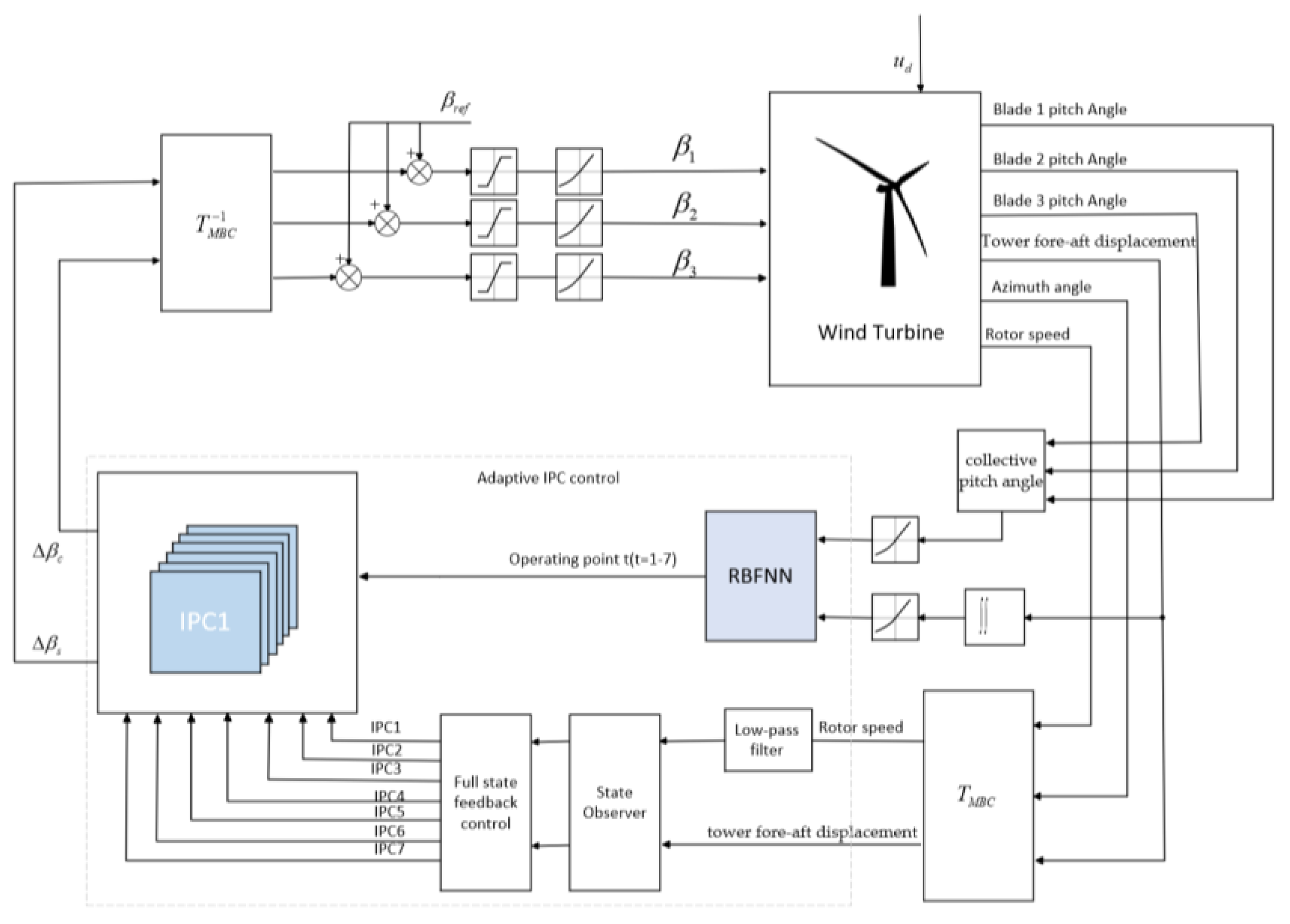
The structure of the adaptive independent pitch control system is shown in Figure 2. The measured output y of the full-state feedback control loop varied by MBC passes through a low-pass filter and is used as the input to the controller, which updates the outputs β c and β s according to Equations (10) and (11) and combines them with the RBF training loop to form the adaptive control, and the outputs are inverted by the MBC and added with the reference value of the steady-state operating point of the pitch angle β r e f and then pass through the pitch angle saturation module, the pitch input signals β 1 , β 2 , β 3 of each blade are obtained from the pitch angle saturation module and the speed limiting module. The independent pitch angle modifies the collective pitch signal to create the control input for the FAST wind turbine model. Given that the IPC gain is designed using a control method that ensures closed-loop stability and targets specific objectives, the robustness and stability of the RBF + AIPC combined control strategy is assured.

5. Simulations Results

5.1. Adaptive Disturbance Control

The state space control accuracy of a wind turbine depends on the number and type of dynamic states modeled. The NREL 5MW wind turbine model is selected for simulation. The model simulation parameters are shown in Table 2 [27].
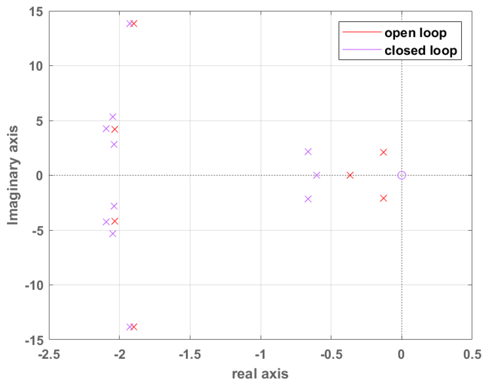
This paper adopts a control system utilizing an 11-state model, which incorporates the damping force of the tower, in contrast to the 9-state model previously considered. To reduce the loads on the wind turbine tower and to perform active control, two additional states are introduced to the 9-state model: tower fore-aft displacement along with its time derivatives. The state matrix A is presented as an 11 × 11 matrix, and the input matrix B is an 11 × 3 matrix. Analysis of the state matrix A gives the open-loop pole −0.37, 1.9 ± 13.8i, −2.03 ± 4.22i, −2.04 ± 2.79i, −2.05 ± 5.32i, −0.13 ± 2.08i. The eigenvectors of the open-loop poles are analyzed, and, following LQR control optimization, the controller gain K x is derived as a 3 × 11 matrix. This adjustment shifts the poles further to the left in the complex plane, enhancing damping and transient response. The closed-loop poles of the system have been derived and are presented in Table 3. Figure 3 gives the open and closed loop pole comparison plot of the system.
To implement a full-state feedback controller for a wind turbine, all states included in the full-state feedback control law (12) must be accurately measured. Achieving this in practical applications is challenging. Therefore, a state observer is designed to replicate the functionality of the full-state feedback controller. A detailed description of the observer design is provided in Section 3.2. The pole positions of the closed-loop system states were selected as −0.6, −0.67 ± 2.13i, −1.92 ± 13.86i, −2.04 ± 2.79i, −2.05 ± 5.32i, −2.09 ± 4.25i. The poles of the state estimator are selected to be positioned further to the left in the complex plane than those of the states being estimated. Following LQR control optimization, the resulting controller gain K d is a 3 × 11 matrix. The closed-loop pole positions estimated by the system are −0.15, −1.54 ± 2.39i, −1.86 ± 13.84, −1.94 ± 4.27i, −2.04 ± 2.81i, and −2.05 ± 5.32i.
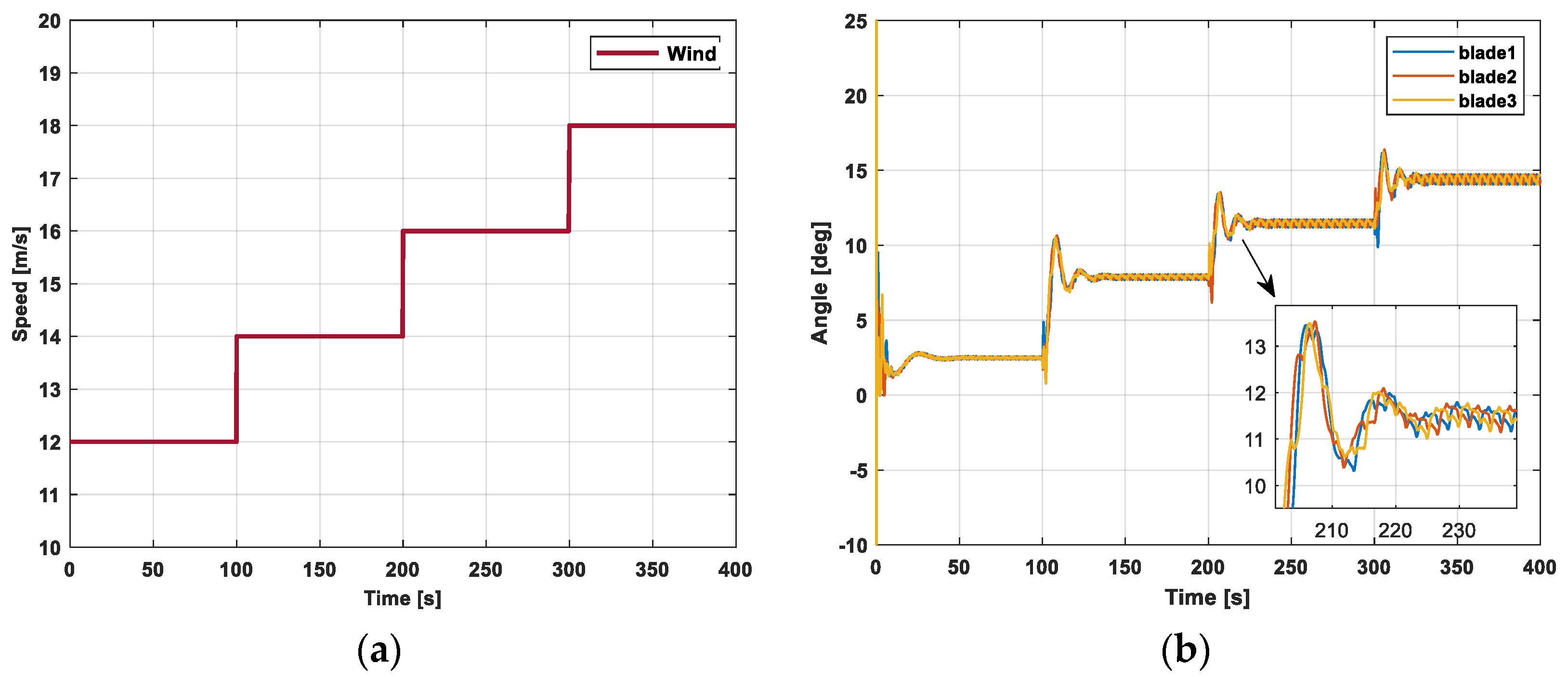
To assess the closed-loop control performance of the DAC-IPC at varying operating points, the step wind profile depicted in Figure 4 is utilized. The hub height wind speed ranges from 12 m/s to 18 m/s. The step size is 2 m/s, and the simulation time is 400 s.
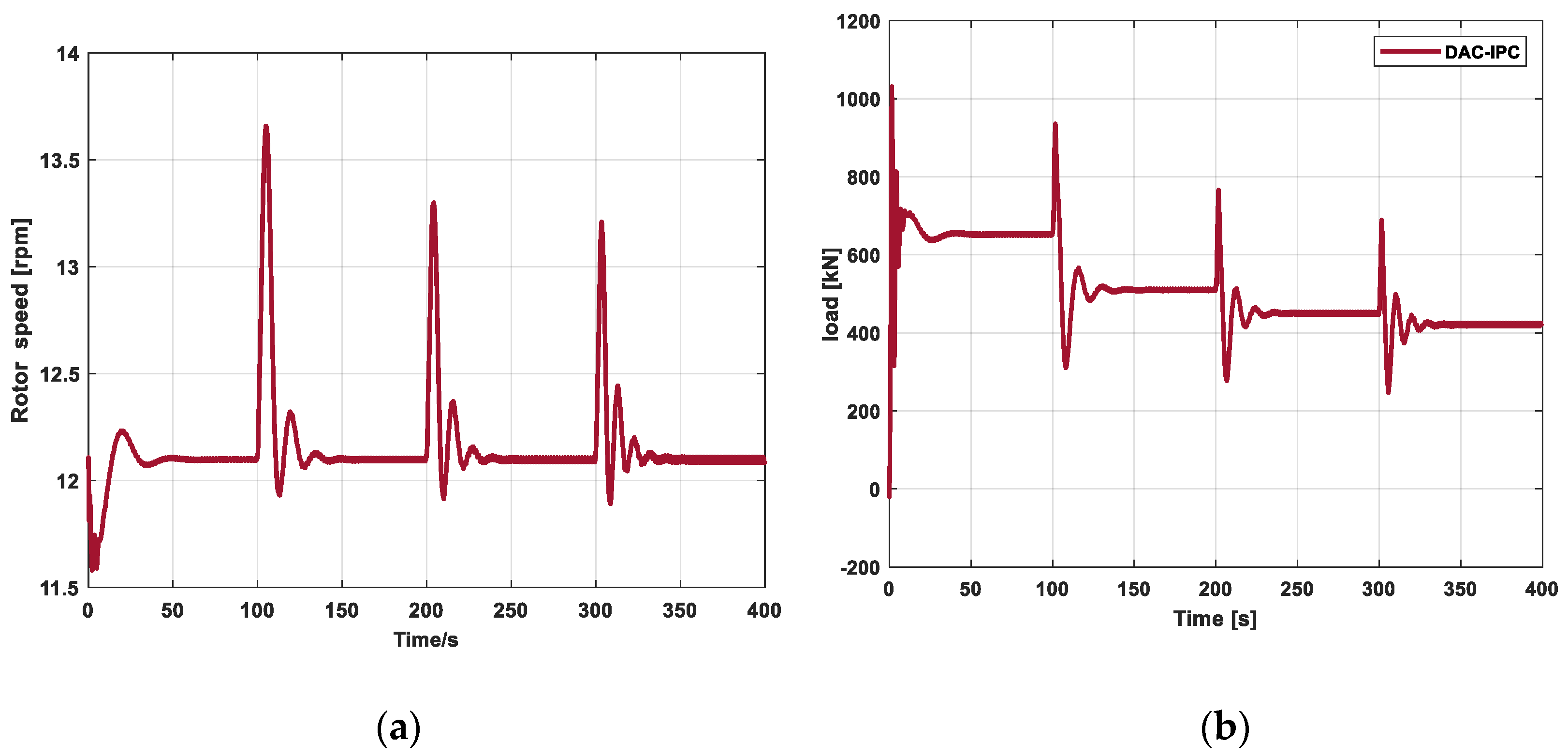
The simulation results are shown in Figure 5, where the rotor speed is regulated very smoothly to keep the rotor speed at 12.1 r/min while keeping the pitch angle within a reasonable range. Compared with the 9-state controller, using the 11-state controller significantly reduces the tower vibration. Therefore, the DAC-IPC controller can both regulate the rotor speed and reduce the tower fore-aft load.
Two scenarios will be implemented to assess the controller’s feasibility in order to validate the RBF neural network adaptive independent pitch controller (AIPC). The first one is the DLC1.1 case. Turbulent winds with different combinations of wind speed, turbulence intensity, and random seeds are generated with Turbsim according to the IEC 61400-1 standard [28]. The turbulent winds are applied to the WTGs, and the response is analyzed. The fatigue loads on the main components are evaluated when operating in a turbulent, full field. The second scenario, DLC1.3, involves extreme operating gusts (EOG) generated by IECWind. These gusts occur within the cut-in and cut-out speeds of the wind turbines and are used to evaluate their dynamic behavior.

5.2. DLC1.1 Working Condition Analysis of RBF-AIPC

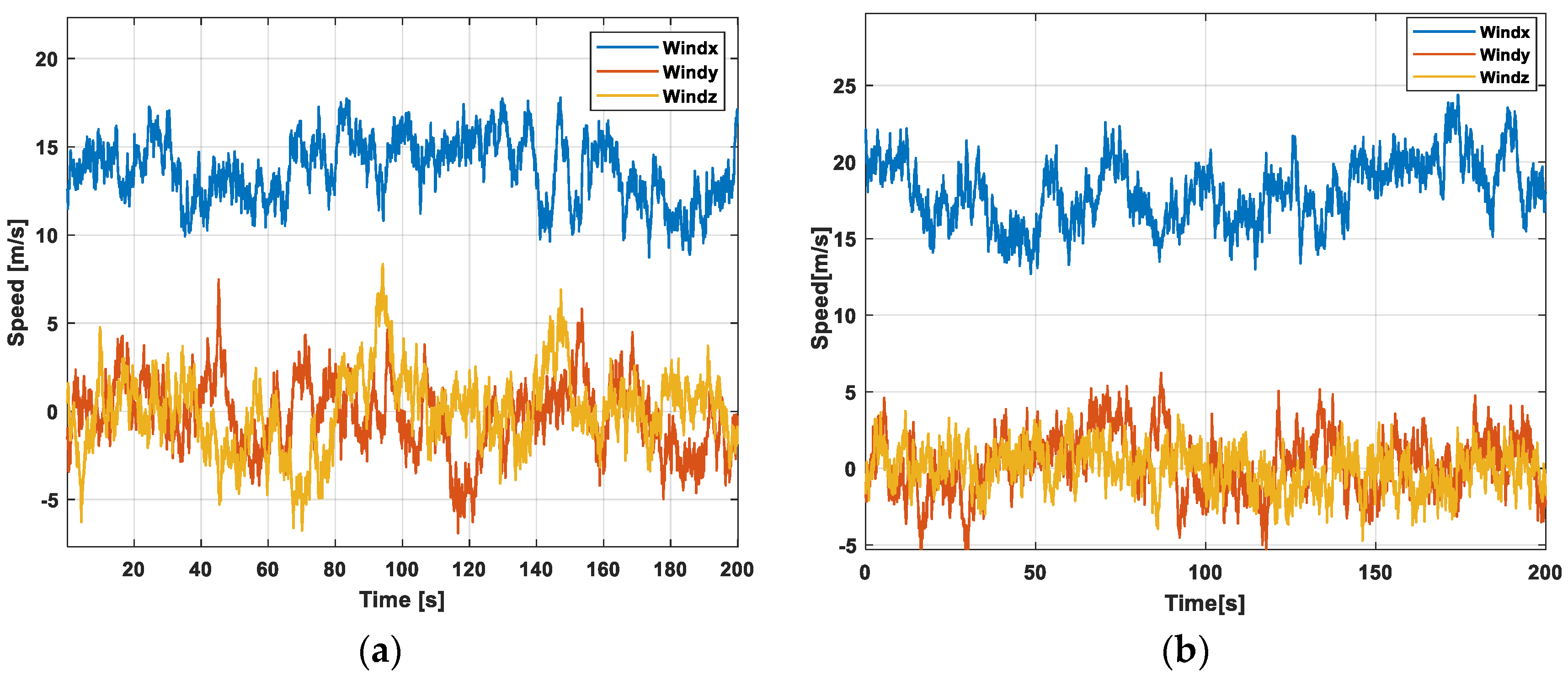
A normal turbulent wind model was generated using TurbSim. The turbulent wind selected for simulation is shown in Figure 6; their average wind speeds are 14 m/s and 18 m/s, respectively. A turbulence intensity of 14.9%, a wind shear coefficient of 0.2, and a simulation time of 200 s.
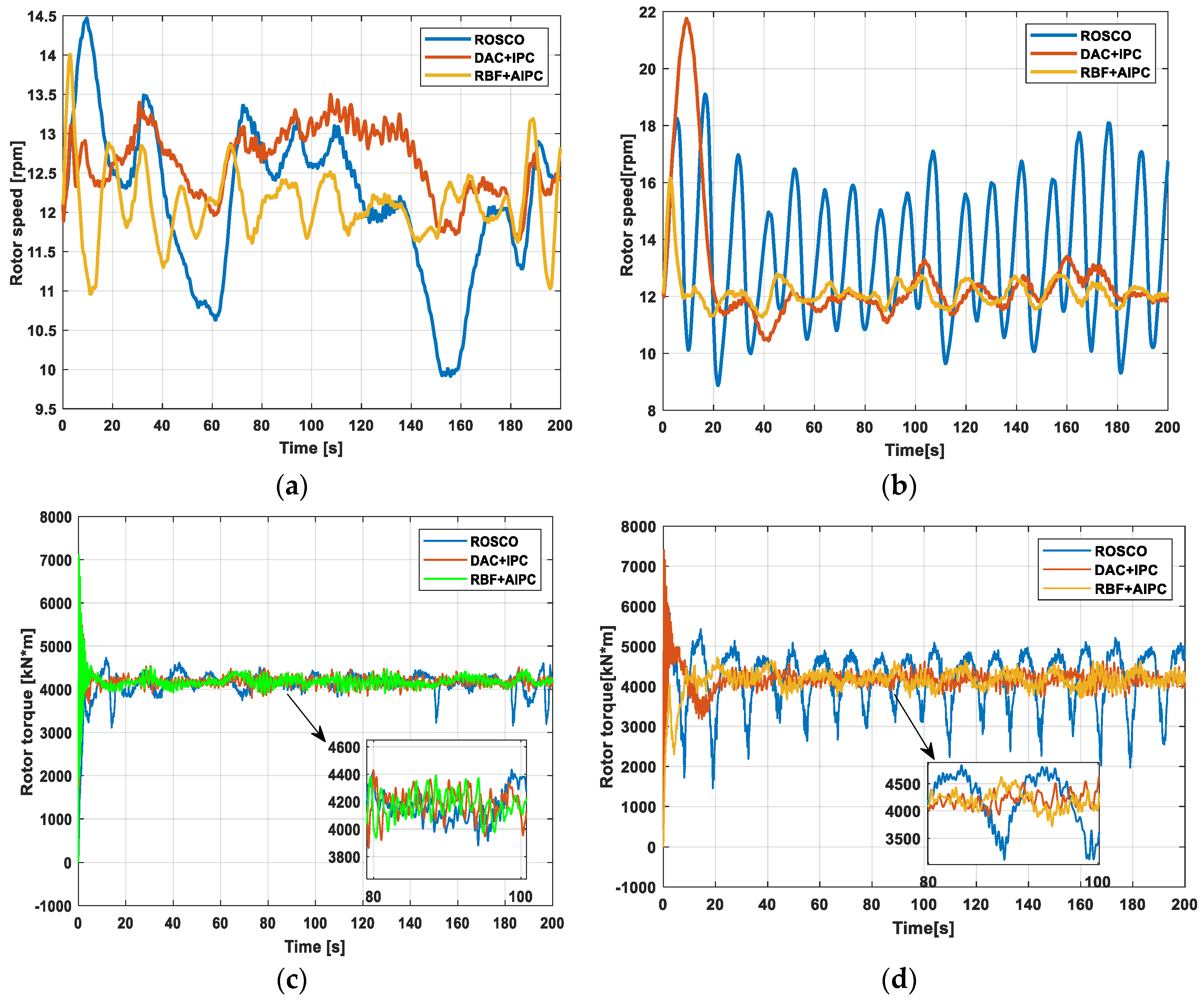
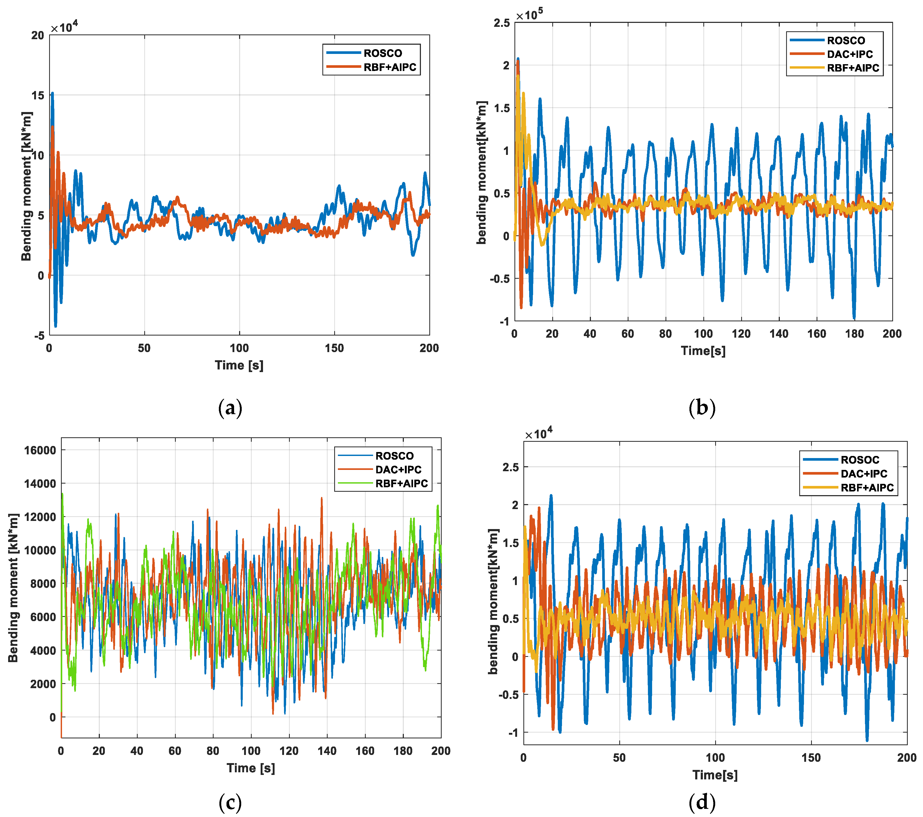
The turbulent wind speed depicted in Figure 6 fluctuates violently with a wide range of variations, which can reflect the uncertainty of the turbine operating conditions and stimulate the nonlinear characteristics of the pitch system. Two experiments were conducted to evaluate the effectiveness of the RBF + AIPC control scheme’s adaptive mechanism across various wind speeds. Separate IPC controllers were designed using linear models based on average wind speeds of 14 m/s and 18 m/s, respectively. Figure 7 and Figure 8 illustrate the control effects, while Table 4 presents the performance results for structural load reduction. As wind speed increases, the DAC + IPC controller exhibits improved performance at the operating point of 18 m/s. Regarding structural load mitigation, the RBF + AIPC controller performs better in reducing blade F-W and tower F-A bending moments at wind speeds beyond the operating point while also maintaining effective rotor speed and torque regulation. This is because the RBF + AIIPC controller requires fewer trade-offs when adapting to varying wind speeds to mitigate loads. Therefore, the proposed adaptive controller demonstrates superior load mitigation by adapting to varying wind speeds without significantly compromising rotor speed and power regulation.
Figure 7 illustrates the variation in rotor speed and torque over time at different wind speeds. When compared to the ROSCO and DAC + IPC controllers at an average wind speed of 14 m/s, the proposed controller effectively regulates the rotor speed to 12.1 r/min and reduces rotor torque fluctuations. Stable operation of the generator is maintained. Quantitative analysis reveals that at 92.2 s, the rotor speed under ROSCO control is 13.08 m/s, whereas under RBF + AIPC control, it is 12.37 m/s, representing a 5.43% reduction. The rotor speed under DAC + IPC control is 13.25 m/s, which is slightly higher than that under ROSCO control. This is attributed to the greater trade-off required between load reduction and speed regulation for the DAC + IPC controller. From Figure 7c, it can be seen that the RBF + AIPC controller has a similar torque control performance to the other controllers with no significant performance degradation or fluctuation. However, at a wind speed of 18 m/s, the rotor speed fluctuates significantly, and the torque exhibits periodic variations. The ROSCO controller’s performance appears inferior compared to the DAC + IPC and RBF + AIPC controllers, which are both effective in reducing rotor and torque fluctuations. Specifically, the average rotor speed is reduced by 7.27% and 10.24%, respectively, under DAC + IPC and RBF + AIPC control. The average torque value was reduced by 1.31% and 2.36%, respectively, for DAC + IPC and RBF + AIPC controls.
Figure 8 illustrates the structural load reduction performance for the tower and blades. The proposed control scheme significantly reduces the variation in blade F-W and tower F-A bending moments. At an average wind speed of 14 m/s, the standard deviations of the tower F-A and blade F-W bending moments are reduced by 34.98% and 7.97%, respectively, compared to the ROSCO controller. When the wind speed increases to 18 m/s, the RBF + AIPC demonstrates superior adaptability, reducing the standard deviations of the tower F-A and blade F-W bending moments by 65.8% and 53.3%, respectively, compared to the ROSCO controller. Table 4 provides the load reduction performance for different controllers. Due to the fewer control objectives, the trade-off between the blade root waving bending moment and generator speed regulation results in only minimal improvement in the mean value of the blade root waving bending moment. However, the unbalanced load is effectively mitigated.

5.3. DLC1.3 Working Condition Analysis of RBF-AIPC

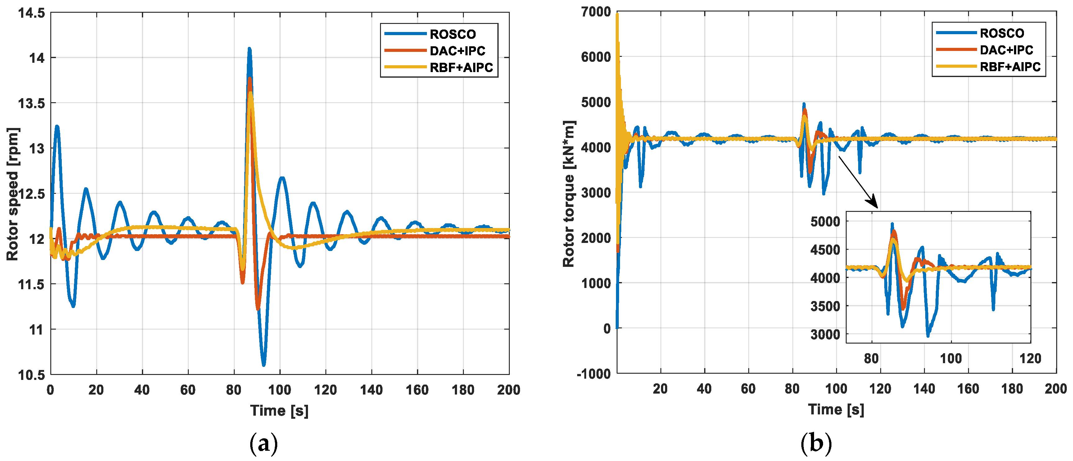
The extreme operating gust generated using IECWind, simulation time 200 s, and simulation time 85 s encountered a sudden increase in extreme wind speed. As shown in Figure 9.
Figure 10 shows the variations in rotor speed and torque over time under extreme wind conditions. Statistical analysis reveals that the standard deviation of rotor speed is reduced by 44.9% and 24.44%, and the standard deviation of rotor torque is reduced by 49.57% and 11.53% with the proposed controller compared to the ROSCO and DAC + IPC controllers, respectively. The ROSCO controller exhibits larger overshoots and slower dynamic response, while the DAC + IPC controller demonstrates better dynamic performance but is associated with more pronounced steady-state errors. Although the RBF + AIPC controller also experiences some steady-state error, its dynamic response is faster than that of the DAC + IPC controller. More detailed comparison parameters with different controllers are given in Table 5.
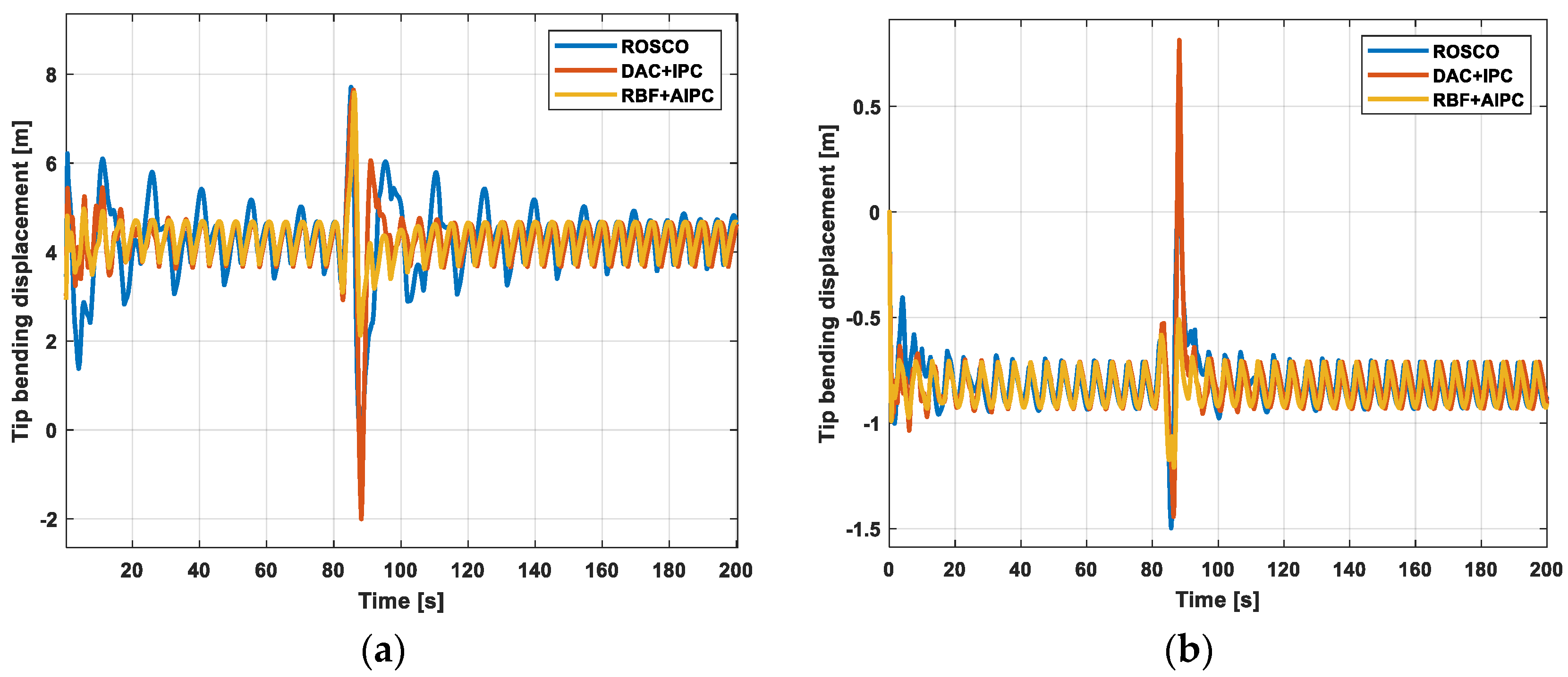
These results indicate that the proposed controller offers superior adaptive and anti-interference capabilities, effectively maintaining stable generator operation. Figure 11 shows the internal and external bending displacement of the blade tip surface. As shown in Figure 11a, there is no significant difference in the maximum values of the internal and external bending displacements of the blade tip surface across the three controllers. However, Figure 11b indicates that the fluctuation in the maximum value of the external displacement is more pronounced. Compared to the ROSCO controller, the standard deviation of the external bending displacement of the blade tip surface is reduced by 31.8%. This reduction effectively mitigates wind perturbations and alleviates fluctuations in both the blades and the associated loads. Table 6 provides the standard deviations of both in-plane and out-of-plane displacements at the tip of the blade for each controller.
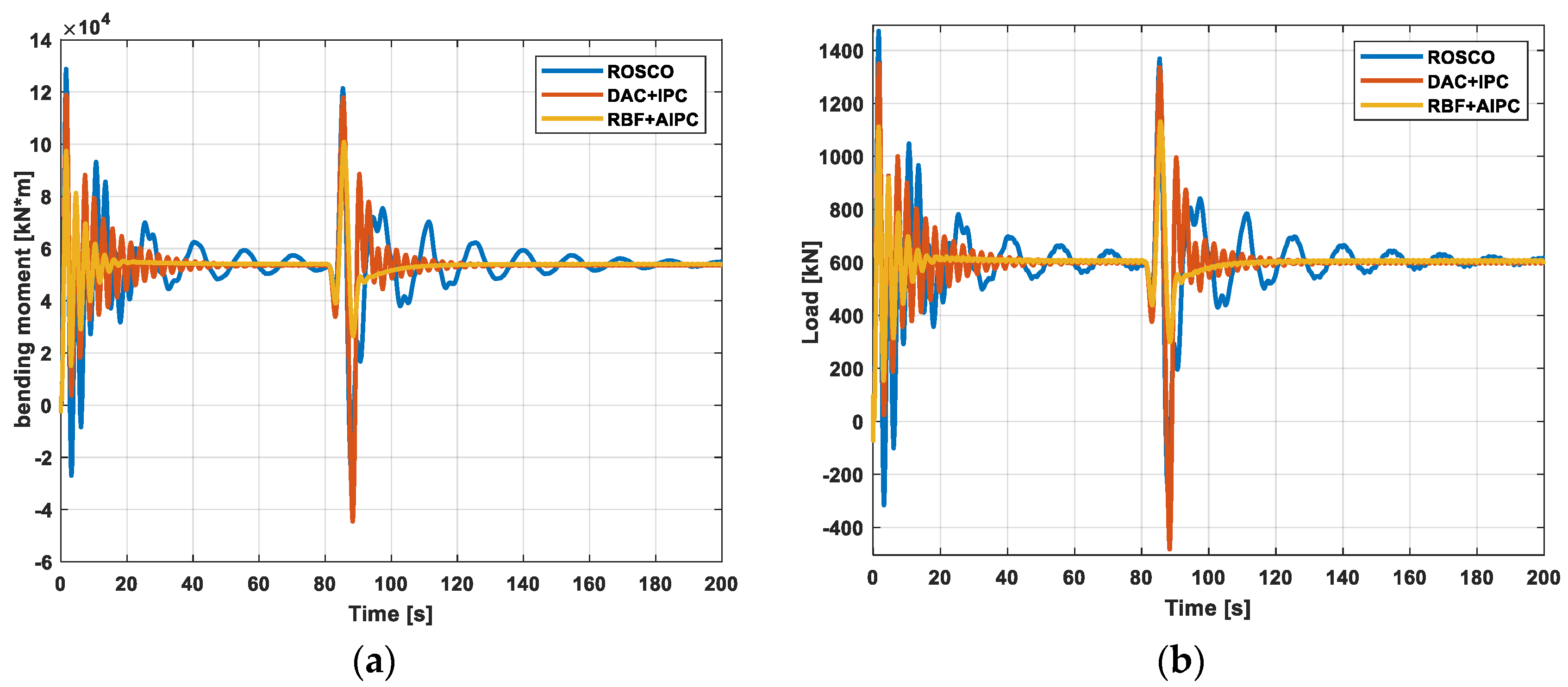
Figure 12 shows the performance of tower load mitigation under extreme gust conditions. Analysis reveals that the proposed control scheme reduces the maximum tower bending moment by 17.13% and 14.53% and the maximum tower longitudinal load by 17.68% and 15.64% compared to the ROSCO and DAC + IPC controllers. This indicates that the RBF + AIPC controller effectively mitigates tower unbalanced loads and vibrations during extreme wind disturbances, enhancing tower load mitigation performance.

6. Conclusions

To enhance system stability and robustness, a multi-objective control approach is employed to comprehensively address rotor speed fluctuation, tower load, and blade load. An independent pitch adaptive control strategy utilizing full-state feedback and perturbation regulation is proposed. A suitable linear time-invariant state space equation is established. Perturbation regulation control is implemented to mitigate the impact of wind disturbances. Additionally, a set of IPC controllers is designed for various operating points, RBF neural networks are employed to train scheduling parameters, and these components are integrated to form an adaptive control loop. The simulation results demonstrate that the proposed controller shows superior performance overall in reducing structural loads and controlling velocity. It is robust to wind turbine modeling errors and nonlinearities and adapts to operating point variations caused by wind disturbances. Additionally, it further reduces tower and blade loads and enhances the stability of wind turbine operation.
The primary limitation of this research is the use of a linearized reduced-order model in the controller design process, which may not fully account for the stability and uncertainty of the closed-loop system. Additionally, unstructured uncertainty has not been analyzed in detail. In practical wind turbine operations, the mobility of the blade pitch actuator is crucial, especially in high wind speeds and turbulent conditions. Future work could explore the use of robust controllers and the development of appropriate weighting functions to reduce the 1P frequency in the blades and enhance control performance. Furthermore, to better characterize uncertainty, future research could incorporate additional system parameter uncertainties, particularly when the wind turbine operates below rated power, which may enhance control robustness.

Author Contributions

Conceptualization, Y.L. and Y.W.; methodology, X.W.; software, Y.W.; validation, Y.W.; formal analysis, Y.L. and Y.W.; resources, Y.L.; writing—original draft preparation, Y.W.; writing—review and editing, Y.W. and X.W.; funding acquisition, Y.L. All authors have read and agreed to the published version of the manuscript.

Funding

This research was funded by the National Natural Science Foundation of China (No.52007124) and Liaoning Province Central Leading Local Science and Technology Development Funds Program Project (2021JH6/10500166) and the unveiling of the list of hanging science and technology research and development special (2021JH1/10400009).

Data Availability Statement

The data that support the research of this paper are available upon reasonable request from the corresponding author and with the permission of the Shenyang University of Technology.

Conflicts of Interest

The authors declare no conflicts of interest.

References

  1. Gambier, A. Pitch control of three bladed large wind energy converters—A review. Energies 2021, 14, 8083. [Google Scholar] [CrossRef]
  2. Didier, F.; Liu, Y.-C.; Laghrouche, S.; Depernet, D. A comprehensive review on advanced control methods for floating offshore wind turbine systems above the rated wind speed. Energies 2024, 17, 2257. [Google Scholar] [CrossRef]
  3. Lio, W.H.; Jones, B.L.; Rossiter, J.A. Estimation and Control of Wind Turbine Tower Vibrations Based on Individual Blade-Pitch Strategies. IEEE Trans. Control Syst. Technol. 2019, 27, 1820–1828. [Google Scholar] [CrossRef]
  4. Lara, M.; Mulders, S.P.; van Wingerden, J.-W.; Vázquez, F.; Garrido, J. Analysis of Adaptive Individual Pitch Control Schemes for Blade Fatigue Load Reduction on a 15 MW Wind Turbine. Appl. Sci. 2023, 14, 183. [Google Scholar] [CrossRef]
  5. El Yaakoubi, A.; Bouzem, A.; El Alami, R.; Chaibi, N.; Bendaou, O. Wind turbines dynamics loads alleviation: Overview of the active controls and the corresponding strategies. Ocean. Eng. 2023, 278, 114070. [Google Scholar] [CrossRef]
  6. Hu, X.Q.; Tan, W.; Hou, G.L. PIDD2 Control of Large Wind Turbines Pitch Angle. Energies 2023, 16, 5096. [Google Scholar] [CrossRef]
  7. Lim, C.-W. A study of a gain-scheduled individual pitch controller for an NREL 5 MW wind turbine. Energies 2024, 17, 246. [Google Scholar] [CrossRef]
  8. Kumar, A.; Kumar, B. Pitch angle Control of Variable Speed Wind Turbine by using Fuzzy Logic. In Proceedings of the 2018 2nd IEEE International Conference on Power Electronics, Intelligent Control and Energy Systems (ICPEICES), Delhi, India, 22–24 October 2018; pp. 56–60. [Google Scholar]
  9. Shawqran, A.M.; El-Marhomy, A.; Attia, M.A. Pitch angle Adaptive PI controller based on heuristics optimization algorithms. In Advanced Machine Learning Technologies and Applications: Proceedings of AMLTA 2021; Springer International Publishing: Cham, Switzerland, 2021; pp. 674–687. [Google Scholar]
  10. Brandetti, L.; Mulders, S.P.; Liu, Y.; Watson, S.; van Wingerden, J.-W. Analysis and multi-objective optimisation of wind turbine torque control strategies. Wind Energy Sci. 2023, 8, 1553–1573. [Google Scholar] [CrossRef]
  11. Lara, M.; Garrido, J.; Ruz, M.L.; Vázquez, F. Multi-objective optimization for simultaneously designing active control of tower vibrations and power control in wind turbines. Energy Rep. 2023, 9, 1637–1650. [Google Scholar] [CrossRef]
  12. Han, Y.; Liu, X. Collective pitch sliding mode control for large scale wind turbines considering load reduction. In Proceedings of the 2014 International Conference on Mechatronics and Control, Jinzhou, China, 3–5 July 2014. [Google Scholar]
  13. Fu, D.Y.; Kong, L.X.; Gong, L.C.; Wang, A.; Jia, H.; Zhao, N. Wind Turbine Load Optimization Control Strategy Based on LIDAR Feed-Forward Control for Primary Frequency Modulation Process with Pitch Angle Reservation. Energies 2023, 16, 510. [Google Scholar] [CrossRef]
  14. Sarkar, S.; Fitzgerald, B.; Basu, B. Individual blade pitch control of floating offshore wind turbines for load mitigation and power regulation. IEEE Trans. Control Syst. Technol. 2020, 29, 305–315. [Google Scholar] [CrossRef]
  15. Bashetty, S.; Guillamon, J.I.; Mutnuri, S.S.; Ozcelik, S. Design of a robust adaptive controller for the pitch and torque control of wind turbines. Energies 2020, 13, 1195. [Google Scholar] [CrossRef]
  16. Kipchirchir, E.; Do, M.H.; Njiri, J.G.; Soffker, D. Mixed-Sensitivity Robust Disturbance Accommodating Control for Load Mitigation and Speed Regulation of Wind Turbines. In Proceedings of the 2022 European Control Conference (ECC), London, UK, 12–15 July 2022; pp. 1012–1017. [Google Scholar]
  17. Kipchirchir, E.; Söffker, D. IPC-based robust disturbance accommodating control for load mitigation and speed regulation of wind turbines. Wind Energy 2024, 27, 382–402. [Google Scholar] [CrossRef]
  18. Wen, H.Y.; Liu, Y.; Lee, S.M.; Park, J.H. Optimal Power Regulating for Wind Turbine with LQR and Disturbance Accommodation Pitch Control. In Proceedings of the 2023 9th International Conference on Control, Automation and Robotics (ICCAR), Beijing, China, 21–23 April 2023. [Google Scholar]
  19. Menezes, E.J.N.; Araújo, A.M.; Rohatgi, J.S.; del Foyo, P.M.G. Active load control of large wind turbines using state-space methods and disturbance accommodating control. Energy 2018, 150, 310–319. [Google Scholar] [CrossRef]
  20. Wang, N.; Wright, A.D.; Johnson, K.E. Independent Blade Pitch Controller Design for a Three-Bladed Turbine Using Disturbance Accommodating Control. In Proceedings of the 2016 American Control Conference (ACC), Boston, MA, USA, 6–8 July 2016; pp. 2301–2306. [Google Scholar]
  21. Wang, N.; Wright, A.D.; Balas, M.J. Disturbance accommodating control design for wind turbines using solvability conditions. J. Dyn. Syst. Meas. Control 2017, 139, 41007. [Google Scholar] [CrossRef]
  22. Kipchirchir, E.; Do, M.H.; Njiri, J.G.; Söffker, D. Adaptive robust observer-based control for structural load mitigation and speed regulation in commercial wind turbines. IEEE Access 2024, 12, 38335–38350. [Google Scholar] [CrossRef]
  23. Fitzgerald, B.; Sarkar, S. Observer based pitch control for load mitigation and power regulation of floating offshore wind turbines. J. Phys. Conf. Ser. 2024, 2647, 032003. [Google Scholar] [CrossRef]
  24. Asgharnia, A.H.; Jamali, A.; Shahnazi, R.; Maheri, A. Load mitigation of a class of 5-MW wind turbine with RBF neural network based fractional-order PID controller. ISA Trans. 2020, 96, 272–286. [Google Scholar] [CrossRef]
  25. Routray, A.; Sivakumar, N.; Hur, S.H.; Bang, D.J. A comparative study of optimal individual pitch control methods. Sustainability 2023, 15, 10933. [Google Scholar] [CrossRef]
  26. Jonkman, J.M.; Jonkman, B.J. FAST modularization framework for wind turbine simulation: Full-system linearization. J. Phys. Conf. Ser. 2016, 753, 082010. [Google Scholar] [CrossRef]
  27. Abbas, N.J.; Zalkind, D.S.; Pao, L.; Wright, A. A reference open-source controller for fixed and floating offshore wind turbines. Wind Energy Sci. 2022, 7, 53–73. [Google Scholar] [CrossRef]
  28. Wind Turbines—Part 1: Design Requirements. Available online: https://webstore.iec.ch/publication/64648 (accessed on 14 August 2024).
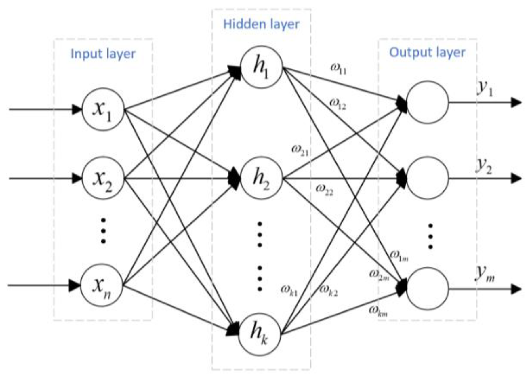
Figure 1. RBF neural network structure diagram.
Energies 17 04619 g001
Figure 2. Block diagram of adaptive independent pitch control system.
Energies 17 04619 g002
Figure 3. Zero-pole contrast diagram.
Energies 17 04619 g003
Figure 4. Step wind response. (a) Hub height wind speed. (b) Blade pitch angles.
Energies 17 04619 g004
Figure 5. Speed regulation response and structural loading in the tower. (a) Rotor speed. (b) Tower fore-aft lode.
Energies 17 04619 g005
Figure 6. Turbulent wind. (a) mean wind speed—14 m/s. (b) mean wind speed—18 m/s.
Energies 17 04619 g006
Figure 7. Speed/Torque regulation response. (a) Rotor speed (14 m/s wind). (b) Rotor speed (18 m/s wind). (c) Rotor torque (14 m/s wind). (d) Rotor torque (18 m/s wind).
Energies 17 04619 g007
Figure 8. Structural loading in blade and tower. (a) Tower F-A bending moment. (b) Tower F-A bending moment. (c) Bladed F-W bending moment (14 m/s wind). (d) Bladed F-W bending moment (18 m/s wind).
Energies 17 04619 g008
Figure 9. Extreme working gusts.
Energies 17 04619 g009
Figure 10. Speed/Torque regulation response. (a) Rotor speed. (b) Rotor torque.
Energies 17 04619 g010
Figure 11. Tip in plane/out of plane bending displacement. (a) In-plane. (b) Out of the plane.
Energies 17 04619 g011
Figure 12. Structural loading in and tower. (a) Tower fore-aft bending moment (b) Tower fore-aft load.
Energies 17 04619 g012
Table 1. Design operating points for the IPC controllers.
IPCWind Speed (m/s)Angle (Deg)Rotor Speed (rpm)
1123.8312.1
2148.7212.1
31612.0612.1
41814.9212.1
52017.4712.1
62219.9412.1
72422.3512.1
Table 2. Simulation parameters of 5MW wind turbine.
ParameterValueUnit
Rated power5MW
Cut-in, rated, cut-out wind speed3, 11.4, 25m/s
Blade pitch range0–90°
Cut-in, rated rotor speed6.9, 12.1rpm
Gearbox ratio1:97-
Rotor, hub radius63, 1.5m
Optimum pitch angle ( β o p t )0°
Hub height90m
Maximum power coefficient ( ρ m a x )0.482-
Optimal tip-speed-ratio ( λ o p t )7.55-
Table 3. System pole configuration.
System ModeOpen Loop PoleLQR Pole Configuration after
Rotor speed−0.37−0.6
Drivetrain torsional mode1.9 ± 13.8i−1.92 ± 13.86i
Blade 1 F-W mode−2.03 ± 4.22i−2.04 ± 2.79i
Blade 2 F-W mode−2.04 ± 2.79i−2.05 ± 5.32i
Blade 3 F-W mode−2.05 ± 5.32i−2.09 ± 4.25i
Tower F-A mode−0.13 ± 2.08i−0.67 ± 2.13i
Table 4. Load control performance indicators.
Load Channel [kNm]ControllerAvg (14 m/s)Avg (18 m/s)Std (14 m/s)Std (18 m/s)
Tower F-A [104]ROSCO4.79904.9661.59744.885
RBF + AIPC4.60413.5061.03801.672
Blade F-WROSCO6619.27012.82311.14267.5
DAC + IPC7188.75155.22116.43145.6
RBF + AIPC6619.44795.62126.81992.3
Table 5. Rotor control performance indicators.
ParameterControllerStd.%
Rotor speedROSCO2.47-
DAC + IPC1.80−27.12
RBF + AIPC1.36−44.90
Rotor torqueROSCO989.94-
DAC + IPC564.26−43.00
RBF + AIPC499.22−49.57
Table 6. Control performance indicators.
ParameterControllerStd.%
In planeROSCO3.52-
DAC + IPC4.22−19.88
RBF + AIPC2.33−33.80
Out of planeROSCO5.63-
DAC + IPC5.823.02
RBF + AIPC3.84−31.8
Disclaimer/Publisher’s Note: The statements, opinions and data contained in all publications are solely those of the individual author(s) and contributor(s) and not of MDPI and/or the editor(s). MDPI and/or the editor(s) disclaim responsibility for any injury to people or property resulting from any ideas, methods, instructions or products referred to in the content.