Abstract
This paper presents the design of an innovative scalable wind turbine emulator. The system’s hardware and software components are described in detail including test results, demonstrating the research potential of the proposed design. The uniqueness of the proposed solution lies in its scalability, achieved despite the use of physical devices with fixed parameters. This scalability allows for the flexible shaping of the system’s structure and parameters, allowing it to emulate both individual wind turbines with a capacity ranging from kilowatts to megawatts as well as aggregated models of entire wind farms. The emulator was developed using the hardware-in-the loop (HIL) concept and consists of a digital part including aerodynamic and mechanical models (wind, rotor, shaft models, disturbances, etc.) and control systems for mechanical and electrical devices within the wind turbine. The digital component has a modular structure, which allows for the replacement of any module of the native control system with the user’s custom designed one and testing its properties over a broad range of parameters. The test results presented in the article demonstrate a satisfactory level of accuracy of the developed emulator.
1. Introduction
The concept of the physical modelling of a wind turbine is based on the use of the physical properties of the environment or a device in combination with a real-time simulation. Typically, these are solutions in which a simulation software produces real-time waveforms of selected signals using an input model coupled to the input signals. The signals are connected via analogue and binary I/O cards. These—usually low-voltage and low-current—signals (e.g., ±10 V, 0.1 A) can be amplified to a level corresponding to the ratings of typical voltage and current transformers used in automation systems in the power industry (e.g., 100 V, 5 A) [1,2]. Such a physical model of a wind turbine is known as a Wind Turbine Emulator—WTE [3,4], Wind Turbine Simulator—WTS [5,6] or Wind Turbine Hybrid Model—WTHM.
This paper describes the authors’ concept and implementation of a Scalable Wind Turbine Emulator (SWTE), which is an improved version of the WTE. The scalability of SWTE is understood primarily as the ability to model wind turbines in a wide range of their rated powers as well as turbine rotor and generator rotor inertia constants. Scalability understood in this way assumes the scaling of WT power to DFIM SWTE power while maintaining the dynamic properties of the modelled one. Obtaining this feature should be considered a significant advantage of the proposed solution, because with one device, it is possible to conduct research on the behaviour of individual wind turbines of different sizes as well as with certain limitations of wind farms. The solution described in this paper provides the widest range of inertia modelling among the WTE variants described in the literature.
The system consists in coupling the engine-generator unit to a digital model of a wind turbine (WT) running in a real-time environment. The aerodynamic and mechanical aspects of the WT are implemented in the digital part of the model. The wind turbine generator is emulated by a suitably controlled physical doubly fed induction machine (DFIM), which can be electrically connected to the power grid and other equipment. The DFIM, which is a part of the SWTE, is driven by a motor controlled via a converter (MI). The use of the low-power DFIM allows for its natural electrical properties to be used to model an actual WT with DFIM.
The novel SWTE solution proposed in this work is an extension of the WTE concept, which combines its advantages with those of other wind turbine test methods and tools:
- (a)
- Simulation programmes;
- (b)
- Wind tunnel testing of scaled wind turbine models;
- (c)
- Wind turbine field tests;
- (d)
- Nacelle test bench;
- (e)
- Physical model of a wind turbine—WTE.
The SWTE (developed from e) is based on the solutions used in the hardware-in-the-loop technique (which is the basis of methods e and d). The technique used combines the versatility of digital models (a) coupled in real time with electrical devices with suitably adjusted properties (modified method d). This concept allows for the safe and reproducible testing of the modelled devices, which would not be possible under real conditions (e) due to the threat of damage to the object under test or the difficulty of triggering and controlling the disturbance. The approach proposed in this article has clear cost-related benefits. The cost of testing using a physical model is a fraction of the cost of equivalent field tests or bench testing of wind turbine nacelles (d). When considering the cost of testing, one must also bear in mind the risk of failure or damage as a result of field tests (c) resulting in costs that are incomparably higher than those of a scalable wind turbine model. The SWTE proposed in this paper allows for the aerodynamic characteristics of the turbine rotor and mechanical parameters to be modelled, making it a sensible alternative to the wind tunnel testing of turbine models (b). This allows for the testing of interactions with the power system and the electrical power equipment within the system in disturbed states, similarly to the wind turbine nacelle test bench, but at a much lower cost and with improved versatility.
2. Literature Review
2.1. Physical–Digital Modelling of Wind Turbines
The idea of creating a physical model of a wind turbine by coupling a computer simulation to an electrical machine that exploits the natural properties of the machine is not entirely new [7,8,9,10,11,12,13,14,15]. The first descriptions of WTEs were published at in the early 2010s [3,5,16]. One of the first descriptions of a physical model of a wind power plant constructed using a 92 kW asynchronous motor—the permanent magnet synchronous generator machine unit—was presented in [5]. In the described system, the angular velocity of the asynchronous motor and the output of the synchronous generator are controlled by appropriately controlled converters. The control signals are generated on the basis of the introduced power characteristics as a function of wind speed and rotor angular velocity. The model does not take into account the inertia of the turbine rotor or the generator. It is a simple model used to emulate steady or slowly varying states.
The literature review has identified key elements of the WTEs described in the literature:
- Software environment/driver;
- Wind modelling;
- Inertia modelling;
- Selected applications.
The coupling of WTEs via analogue and binary inputs requires the handling of these signals in a real-time simulation. Depending on the actuator and the software platform (environment) used, the following physical models of the wind turbine can be specified:
- Models with A/D and D/A converters, possibly using a power amplifier:
- (a)
- In a real-time simulator;
- (b)
- In a simulation program running in a real-time environment.
- Models with an electrical machine:
- (a)
- In a simulation program running in a real-time environment;
- (b)
- In a real-time simulator;
- (c)
- In programmable controllers.
Specialised real-time simulators (1a) that enable the simulation of the electrical waveforms of selected state variables of electrical devices operating in the power grid have the greatest real-time simulation capabilities. Real-time simulators are used for the rapid control prototyping (RCP) of the control system being designed and for the testing of systems or devices electrically connected to the simulator (hardware-in-the-loop—HIL). The best-known real-time simulators are the following:
- RTDS (real-time digital simulator) from RTDS Technologies [17], the leading platform for real-time simulators. An example of modelling a wind power plant performed in the RTDS real-time simulator is presented in [18].
- Opal-RT—a family of hardware products and real-time environments (HYPERSIM, eMEGAsim, eFPGAsim, ePHASORsim). An example of a WT model implementation was described in 2004 [16], where a WT with DFIM was the subject of the study. The simulation part of the model was built from elements available in the electrical model library SimPowerSystem coming from MATLAB Simulink.
The first group of software platforms is completed by simulation software adapted to work in a real-time environment (1b). The manufacturers of the software that simulate the operation of the power grid and its components have extended their functionality by adding a real-time environment and interfacing with input/output cards. Examples of implementations of WTEs based on Simulink Real-Time (SLRT) and Netomac can be found in the literature:
- Simulink Real-Time. Owing to the SLRT environment, the simulation models of MATLAB Simulink can run in real time in coupling. An example of the use of WTE models is described in [19,20,21], and WTE with PMSG and WTE with DFIM performed in the LINTE^2 Laboratory.
- Netomac. Software for the simulation of power system operation, in particular for the study of dynamic states. An example of a wind turbine model operating in real time with a sampling time of Tp = 1 ms is described in [22].
The second group of WTEs includes emulators that use a real electrical machine as the emulating element of the WT generator (2) together with a programmable circuit or signal processor-based controller. Examples grouped by software platform include the following:
- dSPACE from dSPACE GmBH—together with a specialised real-time card, e.g., DS1104 allows the use of MATLAB Simulink models in the form of code written in C, used for example in [7,15,23];
- Programmable circuits based on digital signal processor (DSP-based) [8,10,13,24];
- Circuits based on field programmable gate array (FPGA) [25].
Software development environments dedicated to control and measurement systems from National Instruments are used for programmable systems:
- For programming in C—LabWindows/CVI [8,14],
- For graphics—LabView [26,27].
Analysing the software platforms used for physical models, it can be concluded that real-time simulators are the most expensive, fastest (typically fp = 20 kHz), have extensive libraries, and provide software-in-the-loop testing capabilities with simulated machines and power electronic devices, as well as allowing the creation of models in a convenient environment and convenient real-time access to parameters, variables, and signals. In contrast, simulation software running in a real-time environment is less expensive than real-time simulators, has extensive libraries, and offers software-in-the-loop testing with simulated machines and power electronic devices. The creation of models and control panels in a convenient environment and real-time access to parameters, variables and signals are among the advantages of the solution.
Programmable systems are widely used in control systems, are less expensive than real-time simulators, fast (typically fp = 5–10 kHz), and can be programmed in C or in a graphical environment (e.g., LabView), with libraries for control system applications and with no software-in-the-loop testing.
An analysis of the software platforms used for physical models led to the conclusion that Simulink Real-Time is the optimal choice, due to the convenience of creating the digital part of the model and the extensive library of models and modules, the availability of tools for creating the operator station, and the widespread familiarity with Simulink software among engineers. Simulink Real-Time achieves a sampling rate of 1 kHz sufficient to build a usable real-time digital model at an acceptable software cost.
2.2. Wind and Engine Inertia Modelling in WTE
Disturbances and rapid changes in wind speed can be observed on the mechanical torque waveform on the shaft. By including the phenomena causing the disturbances in the WTE, it is possible to carry out individual studies of the influence of wind phenomena on wind turbine operation. In most publications on physical models of wind turbines, a simple model of medium or slow variable wind is utilised [19,23]. In some publications, the authors describe an enhanced wind model with a turbulence component [24,25,28]. In [24], the turbulence component is modelled in a simple way using the harmonic series. In [25,28], the Kaimal model, recommended in IEC 61400-1 [29], is used as a turbulence generator.
The tower shadow effect is a phenomenon often included in wind turbine simulation models [13,24,30,31]. At times, it is the main phenomenon simulated and described in the publication [3]. The authors of [31] modelled the shear effect, which is the change in wind speed with height [32,33,34]. Although these phenomena are associated with the wind, unlike the variable components of wind speed such as turbulence, their effect on the shaft torque depends on the turbine rotor angle (the position of the blades relative to the tower).
The dynamic properties of a wind turbine can be observed during the disturbance states on the generator rotor speed and active power waveforms. A key aspect that determines the dynamic properties of the physical model is the inertia of the rotating elements in the machine unit. The use of a single-mass model without compensation [5,10,27] or a single-mass model with a simple moment of inertia correction [13] or with compensation from the generator rotor speed [3,11] or with compensation from the speed derivative [9,31,35,36,37] was common in the physical model implementations described in the reviewed publications. A high-power WT emulation using a single-mass model does not take into account torsional oscillations on the shaft between the generator and the turbine rotor.
The correctly modelled dynamic properties of a wind turbine require an accurate representation of the WT-simulated generator speed of the WTE generator. It is necessary to use a two-mass model of the turbine shaft, as implemented in SWTE.
2.3. Selected Implementations of WTE
Physical models of wind turbines described in the literature are simple implementations with the modelling scope usually limited to the CP power conversion function, focusing on the presentation of a selected aspect, e.g., the tower shadow effect. The publications include descriptions of model implementations where the focus is on qualitative modelling (preserving the waveform of the emulated phenomenon) rather than quantitative modelling (preserving the exact scale between signal/measurement quantities). Some publications on wind turbine emulation examine the issue of the different inertia of the rotating elements of the modelled wind turbine and the machine unit of the physical model of the wind turbine. The first proposal to address the aforementioned issue in the emulator, through the appropriate compensation of the generator inertia, was presented in [13]. The essence of these solutions is that the simulation is entirely software-based. The purpose of most published presentations of physical models of wind turbines is to emulate static or slow-moving operating points with the accompanying visual effect given by the running generator. Even when the authors refer to them as ‘educational workstations’, it can be usually concluded that they serve as the ‘demonstration workstations’ of a machine unit rather than wind turbine models. This is due to the black box approach—the implementation of input–output characteristics without the introduction of typical turbine rotor model structures and control system.
Notable studies involving physical models of wind turbines include the following:
- Testing of protection systems, e.g., grid and wind power plant model in Netomac software, interface—Dinemo [22].
- Comparative studies of the waveforms of two wind turbine physical model systems [38]. In the first system, the driving torque on the turbine rotor shaft was produced by blowing a rotor with a stream of air simulating wind. In the second system, the turbine rotor was replaced by an asynchronous motor.
- Emulation of the microgrid model operation [39]. Possibility of synchronous operation with the grid and transition to island operation. Developed for, among other things, power quality studies.
- Use of a physical model of a wind turbine for testing control algorithms. In [12,40], the use of an MRAS (model reference adaptive system) observer in a wind turbine control system is described.
- Study of the use of Electromagnetic Frequency Regulator in a wind turbine [4,41].
- Study of the effectiveness of passive turbine power control using a furling angle mechanism in a small 1.2 kW wind turbine [42].
- Study of vibrations in the gearbox and stress in the rotor blades [28].
- Studies using a wind speed signal from a current measurement for emulation [43].
The literature review carried out by the authors allows us to conclude that, although numerous physical models have been developed, they were intended to analyse a narrow set of research problems, always for a specific wind turbine (with specific mechanical and electrical parameters). Dynamic phenomena occurring in a wind turbine are seldom addressed. Most of the models found in the literature focus on the static characteristics of the conversion of wind energy into electricity (conversion function).
The physical model presented in this paper builds on and extends the models described in the literature. The developed solutions facilitate the analysis of a wide range of issues related to the operation of modern wind turbines with different power ratings. The model allows for investigating energy conversion issues, mechanical and electrical issues, as well as analysing and testing control systems.
3. Implementation—SWTE Test Bench
The result of the work on the concept presented in this paper is the SWTE test bench (Figure 1b). The test bench is located in the Laboratory of Innovative Electrical Technologies and Integration of Renewable Energy Sources LINTE^2 of the Faculty of Electrical Engineering and Automation of the Gdansk University of Technology [44].
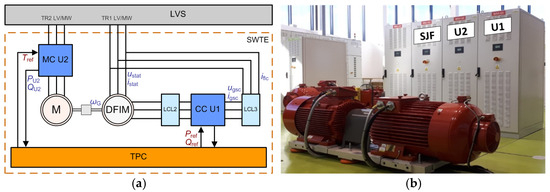
Figure 1.
Wind turbine emulator in the LINTE^2 Laboratory: (a) schematic diagram; and (b) test bench.
A schematic diagram of the SWTE concept is shown in Figure 1a. According to the concept, the main components include the following:
| TPC | – | simulation computer, also known as Target PC in HIL technology; |
| DFIM | – | doubly fed induction machine, which works as a generator; |
| M | – | asynchronous squirrel cage induction motor driving the machine unit; |
| MC (U2) | – | rectifier and inverter of the converter controlling the asynchronous motor; |
| CC (U1) | – | rectifier and inverter of the coupling converter of the doubly fed machine; |
| LCL2 | – | LCL filter of the coupling converter on the rotor side of the DFIM; |
| LCL3 | – | LCL filter of the coupling converter on the stator side of the DFIM. |
The SWTE is connected to the low-voltage configuration switchgear (LVS).
The electrical signals of the unit are available on the simulation computer:
| ustat, istat | – | phase voltage and stator current, instantaneous values in the three phases; |
| ugsc, igsc | – | phase voltage and current at the converter terminals in the rotor circuit of the coupling converter at grid side converter (at the converter terminals before the filter), instantaneous values in three phases; |
| iflc | – | current in the rotor circuit behind the capacitive filter connected to the converter in the rotor circuit of the coupling converter at grid side, instantaneous values in three phases; |
| PU2, QU2 | – | active and reactive power feeding the asynchronous motor. |
Signals controlling the machine unit through the converters:
| Tref | – | pre-set electromagnetic torque of the converter controlling the asynchronous motor; |
| Pref, Qref | – | pre-set active and reactive power of the stator DFIM controlled by the coupling converter. |
In Figure 1b, in the foreground, a machine unit can be seen: an asynchronous squirrel-cage induction motor (left) and a doubly fed generator (right). Behind the machine unit, the converter cabinets, of which the two on the right are part of the SWTE (the asynchronous squirrel cage induction motor control converter U2 and the coupling converter of the doubly fed machine U1).
The implementation of the physical–digital model of the wind turbine in question is based on the hardware-in-the-loop (HIL) technique. HIL works particularly well for testing prototype systems and testing systems with modified software.
At the core of the HIL workstation is a computer (Target PC) with input/output cards together with isolation circuits, and a real-time environment to run applications of the device part model, control systems, and the environment. The applications simulate the behaviour of the modelled components in real time, which translates into the ability to track input signals with a sufficiently short sampling period and to respond to them without delay, which is relevant for the observed phenomena.
A functional diagram of a physical–digital model of a wind turbine with a two-sided asynchronous generator is shown in Figure 2.
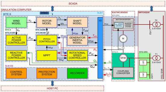
Figure 2.
Block diagram of SWTE with a doubly fed induction machine (the description of signals can be found in Appendix A).
The main components of the bench together with the operating environment of the scalable physical model of the wind turbine (Figure 2) include the following:
- Simulation computer—with Simulink Real-Time environment (SLRT);
- Electrical equipment—with machine unit (motor–generator set);
- Switchgear—consisting of two parts, supplying the equipment emulators and supplying the auxiliaries;
- An operator station.
The SWTE consists of two main components: the digital part of the physical model of the wind turbine—WTE.S and the generator, emulated by the DFIM with a coupling converter—WTE.G. The setup is completed by the actuators (electric drive)—WTE.DRV: an asynchronous squirrel cage induction motor (M) and the converter supplying it, which together make up the drive of the machine unit.
The digital part of the physical model of the wind turbine (WTE.S) is made up of three main functional components: the WT aerodynamic and mechanical models (WTE.A&MM), the controllers of the mechanical part of the SWTE (WTE.MCSM), and the electrical power controllers (WTE. ECSM). The MCSM includes a pitch controller, a speed controller, and a maximum power point tracking (MPPT) module. The WTE.A&MM together with the WTE.DRV emulate the rotor and shaft of a wind turbine by applying a mechanical torque to the rotor shaft of the generator.
The ambient model of the modelled WT consists of a simulated part (WTE.S), modelling the wind speed, and an emulated power system (WTE.GRD). The model of the power system to which the SWTE is connected is emulated in a separate part of the low-voltage switchgear (LVS1). LVS1 is fed by a separate 0.4/1 kV transformer (T1), and models of other power or electrical devices UE1–UEn can be connected to it. The WTE.DRV, as well as actuators of the other emulated devices, are connected to the switchgear LVS2, which is fed by a separate 0.4/1 kV transformer T2. By feeding the models of the devices and their actuators with separate LV/MV transformers, unwanted electrical interactions between the devices were eliminated. Transformers T1 and T2 were supplied from the medium-voltage switchgear (MVS) of the Gdansk University of Technology.
The simulation computer is responsible for controlling the machine unit via the M power converter, in particular the speed and active and reactive power of the generator. The key functions of the model application include the following:
- Simulation of the operation of the mechanical part of the wind turbine (WTE.A&MM);
- Simulation of the operating environment of an emulated wind turbine (WM);
- Simulation of the operation of the control and protection systems of the wind turbine (C&PS);
- User interface and operation of override systems;
- Protection system for the operation of the physical model of the wind turbine;
- Recording of fault conditions causing an emergency shutdown.
The simulation computer is a PC running in the Simulink Real-Time (SLRT) environment equipped with input/output (I/O) cards. Algorithms emulating the selected elements of the wind turbine (models: wind, blades, inertia, faults, control of the machine unit including converters, protection systems and the recording module) together with all control systems operate with a sampling period Tp = 1 ms. The components of the model can be grouped as follows:
- Aerodynamic and mechanical system model (A&MM):
- ▪
- Wind turbine rotor and inertia models;
- ▪
- Shaft model;
- ▪
- Generator inertia model;
- ▪
- Disturbances and mechanical phenomena affecting the moment on the shaft.
- Wind model (WM)—model of wind speed and disturbances;
- Mechanical control systems model (MCSM);
- ▪
- Pitch controller;
- ▪
- Maximum power point tracking system (MPPT);
- ▪
- Rotational speed controller.
- Electrical control systems model (ECSM):
- ▪
- Active power controller;
- ▪
- Reactive power controller.
The I/O RT-DAC4 card allows the timing circuits on the card to trigger the processing of input signals (Figure 3a). The implementation of the SWTE required adapting the hardware-in-the-loop structure of the model to stabilise the synchronised operation of the simulation model with other laboratory units in coupling with the converters and the machine unit. Simulink Real-Time interacts with the I/O card via the interrupt system. Measurements are read by the card reporting a system interrupt, which is then implemented by the BIOS interrupt handling system. This action extends the reading time of the analogue inputs of all cards by the execution time of the system interrupts. The use of the available interrupt handling functions on the PCI bus, which is not adapted to the physical system operation, resulting, at times, in non-synchronous operation and even a loss of (unhandled) interrupts. For the project presented in this paper, a new way of interfacing the model’s SLRT application with the I/O cards in the Simulink Real-Time environment was developed. The original method of interfacing used by the card manufacturer was based on handling interrupts that were initiated sequentially. In order to significantly accelerate data exchange, the method of operation of the cards was changed by introducing a function to initiate processing with the edge of an external rectangular pulse. The completion of input reading triggers the execution of the model calculation cycle and sending of control signals to the outputs. If the controller is equipped with more than one card, they are all triggered simultaneously by an external synchronising rectangular signal. This solution eliminates delays resulting from the use of the BIOS interrupt system on the computer’s motherboard to trigger the cards. The author’s synchronisation algorithms were implemented by the card manufacturer InTeCo, Kraków, Poland (Version: RT-DAC4/PCI XILINX version 9.05/Gdańsk). The schematic diagram of the synchronisation of the card’s analogue input reading from the RT-DAC4 card is shown in Figure 3b.
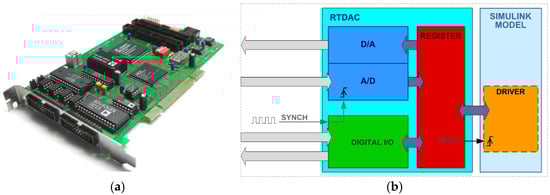
Figure 3.
RT-DAC4/PCI I/O card: (a) view of the card; and (b) schematic diagram of the implementation of the external synchronisation of the RT-DAC4/PCI card input reading process XILINX version 9.05/Gdansk.
The developed solution allows for the synchronised operation of multiple Target PC units of different physical models employed in the research experiment in a joint configuration. In each of the physical models, the signals are sampled at the same time.
The electrical devices of the physical–digital model include a motor-generator machine unit on a common shaft, together with the converters and their control systems. The purpose of the operation of the physical–digital model is to replicate the behaviour of a real WT high-power generator with the SWTE machine unit generator. An asynchronous squirrel-cage induction motor is controlled from the SWTE controller by means of a power converter. The appropriately controlled asynchronous motor emulates a wind turbine and drives a doubly fed asynchronous generator via a common shaft.
- The SWTE units comprise the following:
- An asynchronous squirrel-cage induction motor (M);
A transistorised converter with controller controlling the asynchronous motor (MC—in Figure 1b: WG2-U2).
Both of which are part of the structural part of the WTE.M&MM:
- Doubly fed induction machine (DFIM);
- Transistor converter together with the controller feeding the rotor winding of the doubly fed induction machine (CC—in Figure 1b: WG2-U1),
Both of which form part of the structural part of the SWTE: GEN.
The digital part of the physical model of the wind turbine was created in Simulink and has a clear hierarchical 6-level modular structure. Level I controls the I/O card drivers and the synchronisation of the digital part of the SWTE (Levels II–VI). The digital model contains all the key elements of a real wind turbine. Owing to the graphical representation of the modules depicting the performed functions, the model is intuitively readable with clear signal waveforms, which significantly increases its educational value (Figure 4).
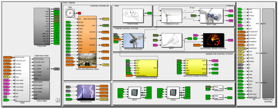
Figure 4.
Structural organisation of the Simulink Real-Time SWTE simulation model—Level II view of the structure.
Table A2 Laboratory. The model parameters are loaded using a file written in MATLAB R2016b. The SWTE includes an extensive control module, incorporating the functions available on the wind turbine control panel. The model can be managed via a remote computer (Host PC) in the slrtexplr application in the Simulink R2016b environment, via a terminal desktop designed for this purpose, or from the laboratory desktop of the SCADA system (Figure 5).
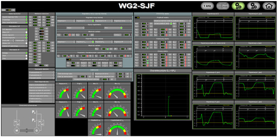
Figure 5.
View of the SWTE control panel in the LINTE^2 Laboratory SCADA system.
The compiled model runs in the controller as an application in the Simulink Real-Time environment. The application performs the differential equations of the model’s algorithms with a sampling period of Tp = 1 ms, which from the point of view of the simulated processes is short enough not to affect the quality of the simulation.
The power system emulator consists of an LV/MV transformer emulating the point of connection to the rigid network and emulators of devices operating in the network in the vicinity of the WT under study. Elements of the emulated grid can include physical models of synchronous generators, receivers, HV/MV lines, ULTC transformers, HVDC links, FACTS systems (STATCOM, SVC, UPFC), photovoltaic sources and others. A description of the Laboratory’s testing capabilities and example tests can be found in Chapter 5.
4. Coherence of the Parameters and Characteristics—Scalability of the Physical Model
4.1. Data Determining the Modelled WT and Operating Conditions
In this paper, scalability is understood as the ability to emulate a wind turbine with a doubly fed asynchronous generator of any capacity. With this in mind, special attention has been paid to the coherence of all parameters and characteristics. Inconsistencies in the parameters and characteristics can significantly distort the results obtained and, in extreme cases, lead to incorrect model operation. This issue also applies to the modelling of wind turbines in simulation software, where dynamic aerodynamic and mechanical states are factored in.
It is virtually impossible to find a consistent and complete set of data in turbine catalogues. What can be found in the literature is a description of the relationships existing between the state variables (operating parameters) and example characteristics. This is usually a dataset designed for the issue described in a specific publication and specific to the wind turbine under analysis. The available literature also does not describe a methodology for preparing a coherent set of data based on partial data. For the purpose of this project, a methodology was developed to prepare a coherent set of complete parameters and characteristics needed for modelling a wind turbine. This methodology enables scaling up while maintaining the consistency and relevance of the input data. The preparation of the WT parameters, the environment and the work, as well as checking the coherence of the TW data is carried out using the following scripts developed in MATLAB:
- I.
- Script defining the basic data and parameters of the modelled wt;
- II.
- Script defining the basic data and parameters of the wind speed and its disturbances;
- III.
- Script defining the control signal variables from the scada system;
- IV.
- Script defining the parameters of the voltage, current, and power measurement transducers;
- V.
- Script defining supplementary parameters (such as filter parameters, correction characteristics of a/d converters);
- VI.
- Script of parameters of automatically executed sequences, which allows the automatic start-up of the model and simulation of a sequence of events (e.g., change of wind parameters, change of operation modes of control systems, etc.).
- VII.
- Application that prepares and verifies a complete coherent set of data of the modelled wind turbine prepdat (preparation of a complete coherent set of data and parameters for emulated wind turbine).
The basic data and parameters of the modelled wind turbine are defined using MATLAB scripts (scripts I–VI). The application (script VII) is crucial for defining the parameters of the wind turbine model to ensure its stable operation. The completeness and consistency of the data are verified and, if necessary, the data are supplemented or corrected. The application contains a comprehensive set of defined characteristics described in the source literature, from which any one can be selected, adjusted to the remaining parameters, and entered into the model. Based on the basic catalogue data of the actual wind turbine, the software verifies its consistency and calculates the remaining parameters. The set of data is scaled up to the rated generator output of the machinery unit and then integrated into the SWTE. By integrating the coherent parameters of the high-power WT with the hardware-in-the-loop station of the machine unit, a scalable physical model of the wind turbine can be obtained.
Figure 6 shows the steps in the method for preparing the basic parameters of the WT model. Each step is implemented by a statement defining or calculating parameter values.
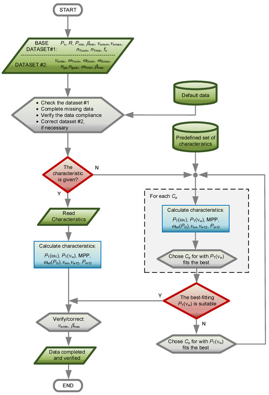
Figure 6.
Simplified diagram of the SWTE parameter preparation and verification algorithm.
This procedure for parameter selection and verification can also be applied to WT simulation models where the model takes into account aerodynamic and mechanical phenomena and where wind speed disturbances are simulated. The detailed methodology for preparing the SWTE model parameters is presented in Appendix B.
4.2. Correct Representation of Machine System Inertia as a Condition for Model Scalability
In the development of a scalable physical–digital model of a wind turbine, the focus was on scalability, understood as the possibility of modelling different wind turbines and, with some simplification, wind farms. In the case of a single wind turbine, it is possible to reproduce disturbances such as turbulence, tower shadow phenomena or mechanical interference, which, when partially attenuated, can be visible on the current and, to a lesser extent, voltage waveforms. In the case of a wind farm, these phenomena are not observable at the terminals of the farm transformer. With the SWTE, a wind farm can be simulated in a manner suitable for the laboratory testing of the modelled grid.
4.2.1. Generator Rotor Inertia—Simulation Methods Using a Two-Mass Model
There are several methods of inertia modelling applicable to WTEs. Depending on how the shaft torque is controlled and implemented, the methods can be grouped as follows:
- Open-loop shaft torque controlRequirements: knowledge of motor loss characteristics:
- ▪
- Mechanical solution with the use of additional rotating massDisadvantages: the need to mount a large rotating mass on the shaft, inconvenient scalability, difficulty of compensating for losses in the motor;
- ▪
- Software solution with the use of a conversion function;Disadvantages: difficulty of compensating for losses in the motor.
- Shaft torque control with the use of torque controllerRequirements: the need to install a high-class shaft-to-shaft rotating torque sensor:
- ▪
- Mechanical solution with the use of additional rotating mass;Disadvantages: the need to mount a large rotating mass on the shaft, inconvenient scalability, lack of a torque sensor, reduced accuracy of the torque sensor in dynamic states;
- ▪
- Software solution with the use of a conversion function;Disadvantages: reduced accuracy of the torque sensor in dynamic states.
- Indirect control of shaft torque with the use of a shaft speed controllerRequirements: the need to install of a rotary encoder:
- ▪
- Software solution using an inertia model:Disadvantages: the implementation requires reprogramming of the converter controllers.
Due to the convenience, properties, capabilities of the WTE and costs, an original method of modelling inertia was used for implementation of SWTE.
4.2.2. Implementation of SWTE on Basis of the Method Using an Inertia Model with a Speed Controller
In order to correctly represent the operation of both an individual wind turbine and the entire wind farm, it is important to correctly represent their dynamic properties. The dynamic properties of a wind turbine determine the waveforms of the state variables in transient states. They are related to the parameters of the control systems and to the inertia of the rotating elements. The dynamic properties of the WTE related to the parameters of the control systems are modifiable, as in the case of the modelled SW. For a physical model of a wind turbine, its ability to model the inertia of the generator of the wind turbine being modelled is crucial. Modelling the inertia of the wind turbine is among the key issues that determine the quality of the wind turbine operation.
In the solution presented in this paper, an additional generator inertia model is used to determine the expected velocity ωGM (taking into account the required inertia), which the controller maintains on the shaft of the machine unit by controlling the M converter (ωref = ωGM). The speed controller is implemented in the M control converter controller (Figure 7).
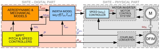
Figure 7.
Variant of the DFIM of the SWTE control concept using an inertia model with a speed controller in the M control converter controller.
The M control converter controller measures the angular velocity using an absolute encoder. The controller operates at a much higher sampling frequency of 16 kHz than the physical model controller (1 kHz), which achieves a better control performance than the speed controller executed in the SWTE simulation computer.
Several validation tests were carried out to confirm the validity of the proposed solution, including a study involving emulation of a WF operation. The detailed model of the wind farm available in Simulink (power_wind_dfig_det.slx), which was developed based on [45,46,47], was adopted as the validation model. The authors of [45] presented a validation study of the presented model in [48]. The simulation waveforms of the model were compared with the waveforms obtained with the accurate model in GE Windtrap—the electromagnetic phenomena sensitive simulation programme (EMTP)—obtained for the simulation of the GE 1.5 and GE 3.6 wind turbines with a doubly fed asynchronous generator, and with the waveforms of field tests [46,48].
5. Laboratory Tests of the SWTE
5.1. Tests at the LINTE^2 Laboratory
The SWTE (model version: v21.05) was tested in the laboratory, where it was operated connected to the LINTE^2 Laboratory power grid. SWTE was tested over a wide range of disturbances and operating conditions:
- In each of the control modes;
- Over the full ranges of wind speed and power;
- Over a wide range of programmable wind components;
- With modelled tower shadow phenomenon;
- With all of the modelled resistive torque disturbances.
SWTE can emulate WT operation with predefined wind speed as well as aerodynamic, mechanical, and electrical disturbances. The wind speed and wind disturbances can be changed dynamically during testing. A novice user can familiarise themselves with the simulation potential of SWTE by running it in self-presentation mode. All operating modes and parameters, wind conditions, and disturbances are available in this mode. Once the self-presentation is started, the SWTE presents the WT operation in a pre-programmed sequence, followed by an automatic operational shutdown. Laboratory tests of the SWTE were carried out using an appropriately programmed self-presentation mode. The tests were carried out by emulating the connection of the modelled WT to a rigid network in the circuit shown in Figure 8.
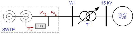
Figure 8.
Simplified diagram of the power grid configuration in the LINTE^2 Laboratory for SWTE testing in the system: wind turbine—rigid grid.
5.2. Model Response to Wind Disturbances
In the tests conducted, the results of which are presented below, the SWTE emulated a GE 1.5 turbine (Pn = 1.5 MW, R = 38.5 m, nT = 20 rpm, TmG = 1.92 s, TmT = 8.66 s). The aim of the study was to show the response of the SWTE to velocity disturbances with two types of a high absolute value of rate of rise. The first group of disturbances comprised gusts, extreme gusts, and coherent gusts with large changes in wind speed. The testing involving these disturbances was intended to demonstrate the dynamic properties of the WT. Testing the response to spikes is one of the basic methods for analysing the performance of the control systems. Instead of non-existent real-world wind spikes, changes with a large rate of rise were taken as excitation. The second type of disturbances comprised turbulence and changes in wind speed due to the tower shadow phenomenon. The tests aimed to show the effect of high-frequency disturbances on speed and power waveforms in particular.
Figure 9 shows the emulated wind speed, which, in addition to the programmable average speed in the rotor axis, was also composed of additive components: faults, gusts, and components related to turbulence and tower shadow phenomena.
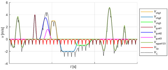
Figure 9.
Wind speed disturbance components: gusts vgust, extreme gusts vegust, coherent gusts vchg (wind shear), tower shadow component v3p, and resultant disturbance component vΣ.
Figure 10, Figure 11 and Figure 12 show the waveforms selected from those recorded during the laboratory tests of the phenomena and disturbances emulated using the SWTE. Figure 10 illustrates the operation of the modelled WT during gusts and extreme gusts and after a step change in turbulent wind speed for two initial speeds: 8 m/s—with a step change to 12 m/s (a) and 12 m/s—with a step change to 8 m/s (b). The wind speed waveform from the Figure 10 is co-created by the wind disturbance components from Figure 9.
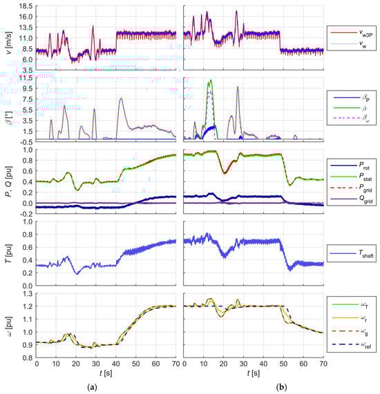
Figure 10.
Model response to forcefully involving a series of gusts including extreme gusts and disturbances (turbulence, 3p effect). The step change in wind speed for an initial wind speed of (a) 8 m/s; and (b) 12 m/s (the description of signals can be found in Appendix A).
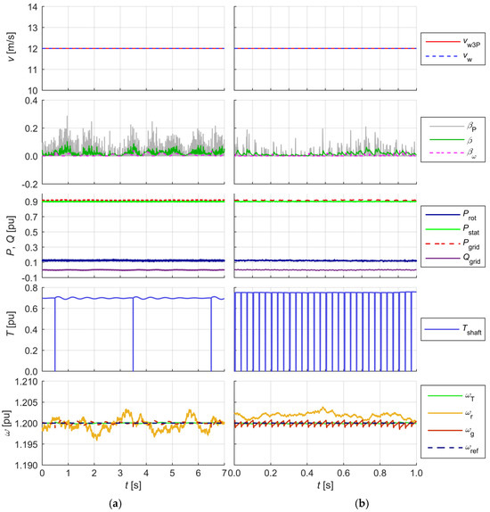
Figure 11.
The waveforms recorded during the SWTE tests. Modelled wheel tooth breakouts of (a) first; and (b) third tooth of a two-stage gearbox.
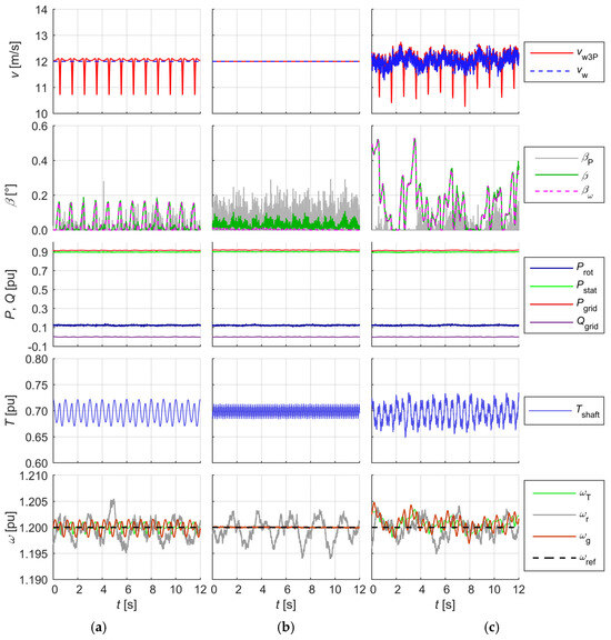
Figure 12.
The waveforms recorded during the SWTE tests: modelled phenomena: 3p effect (k3p = 0.25) (a); mechanical gear tooth stiffness phenomenon (Kd = 0.02) (b); turbulence, misalignment of gear elements (Kncav = 0.05), movement resistance of gear elements related to viscous friction (Bvf = 0.01), mechanical gear tooth stiffness (Kd = 0.02) (c).
Simulated changes in wind speed (Figure 9) induced a change in the mechanical torque on the shaft Tsh, and thus a change in the rotational speed of the turbine rotor. Oscillations on the shaft torque waveform were caused by the 3p effect and turbulence, and due to the inertia of the turbine rotor, they had no noticeable effect on the angular velocity waveforms ωT and ωg. The wind speed disturbances also did not cause noticeable torsional oscillations between the turbine rotor and the generator. The response of the WT control systems to dynamic changes in wind speed can be seen in the waveforms of the turbine rotor blade angle β—an increase in rotational speed above the MPPT setpoint ωref caused an increase in angle β. An increase in rotor speed resulted in an increase in the generated power, which is the effect of the operation of the speed controller, whereas a decrease in speed resulted in a decrease in generated power. The control systems maintained the optimal WT speed (for which power generation was the most efficient) by keeping the angular velocity within the permissible operating range (e.g., 0.7–1.2 p.u.) and electrical power (e.g., 0.2–0.9 p.u.) (the electrical power in relative units was related to the rated apparent power of the generator. The case study assumed a rated active power of the modelled WT of 1.5 MW and a rated apparent power of 1.5/0.9 MVA = 1.67 MVA).
5.3. Investigation of the Effect of a Broken Gear Tooth on WT Operation
Wind turbine accelerating gearboxes typically consist of a planetary stage and two bevel gear stages with a gear ratio of approximately one hundred [49,50,51]. For example, in a GE 1.5 turbine, the gear ratio is either 90:1 or 108:1 (depending on the grid frequency fgrid = 50 Hz and fgrid = 60 Hz at which it is designed to operate at). In order to model the effect of a broken tooth, simplifying assumptions were made: the WT under investigation was equipped with a two-stage gearbox, and the modelling of the broken tooth effect was carried out by zeroing the driving torque on the shaft, synchronised with the shaft rotation, for the duration of which the gear with the broken tooth rotated through the angle between two consecutive teeth. It was further assumed that tooth breakage did not cause jamming, no further damage with rapidly progressive effects occurred, and the turbine shaft continued to rotate. For the purpose of this study, the number of teeth on the first wheel was assumed to be 1260, on the second wheel 70 and on the third wheel 14 (with step ratios of I—18:1, II—5:1). Figure 11 shows the recorded waveforms after one tooth breakage on the first (a) and third (b) gear wheel.
In the example shown, the broken tooth gear had 1260 teeth in case (a) and 14 in case (b). When operating at the rated power at wind speed vw = 12 m/s and 20 revolutions per minute of the turbine rotor, one revolution of the rotor and the first gear (the gear wheels were numbered from the turbine rotor side) took 3 s. A single rotation of the third gear wheel took 0.033 s. The duration time of one wheel tooth rotation was 2.4 ms. In order to better assess the impact of the defect on the operation of the WT, the modelling of other phenomena was turned off.
The reasons for the difference in angular velocities between the turbine rotor and the DFIM rotor result from the properties of the shaft connecting them (stiffness, elasticity) and from mechanical disturbances (friction, damage). After a mechanical disturbance (which results in a change in the total drive torque), torsional vibrations of the rotors in relation to each other appear on the shaft. Oscillations are extinguishing, amplitude damping depends on the stiffness, elasticity, and damping coefficient of the shaft. In the presented example of a disturbance, a gear tooth is broken. This effect is simulated by zeroing the mechanical torque from the moment the gear teeth are lost in contact by the time the gear with the broken tooth rotates by an angle between two consecutive teeth in the gear. The shaft is affected by a braking torque related mainly to the conversion of the kinetic energy of the rotor into electrical energy (fed into the grid). Figure 11 shows the oscillograms of the simulated angular velocity of the turbine rotor ωT and the mechanical torque Tshaft on the turbine rotor. The torque is transmitted through the gearbox to the generator side. The broken tooth causes a disturbance of the angular velocity of the generator rotor ωg—visible in the form of sawtooth deflections. These deflections, if the time interval between successive disturbances allows it, turn into extinguishing oscillations (Figure 11a). The maximum deflection is close to 0.001 p.u. The regulator controls the speed on the shaft (ωr). The maximum adjustment error under these conditions is |ωr − ωg| ≈ 0.0025 p.u. The disturbances caused by the broken tooth are visible on the shaft, but due to the small magnitude of the disturbance, it is not possible to reflect it on the DFIM rotor speed (ωr). The effect can only be seen in the oscillograms of state variables. The impact on voltages and currents fed into the grid is practically imperceptible.
The impact of the broken tooth was clearly visible on the shaft torque waveform as the angular velocity waveforms of the turbine rotor and the generator rotor did not coincide. The implication was that the turbine rotor connected by a shaft to the generator rotor was, to a good approximation, a two-mass system, which was mapped by an appropriate turbine shaft model.
5.4. Investigating the Effects of Other Aerodynamic and Mechanical Disturbances on WT Operation
A further test involved the emulation of the following phenomena:
The aim of this study was primarily to observe the effects of these phenomena on the waveforms, in particular, active and reactive power and the angular velocity of the turbine rotor and generator rotor.
In all three recordings, the effect of the analysed phenomena on the course of the torque on the shaft could be observed. The phenomenon of the mechanical gear tooth stiffness did not significantly affect the course of the generator rotor angular velocity. The determined instantaneous accuracy of the SWTE generator rotor speed emulation (by comparing the angular velocity ωg simulated in the digital part and the measured rotor velocity DFIM ωr included in the hardware part of the SWTE) in static and slow-moving states was higher than 1%. As the signal waveforms of the presented selected tests show, the SWTE allows for the investigation of, among other things, the impact of individual phenomena on the operation of a wind turbine. The physical model of the wind turbine operated correctly in each tested operating mode and simulated conditions.
5.5. Functional Testing of a Physical Model of a Wind Turbine
The aim of the test was to evaluate the dynamic properties of the WT, in particular its mechanical and electrical parts, and control systems. The tests were carried out in the modelled operating system of a WT connected to a rigid grid (Figure 8). The response of the modelled WT to a step change in wind speed vw with a limitation of the absolute value of the derivative of the wind speed component in the turbine rotor axis to 2 m/s2 was investigated. In the test with frequency compensation attached, a frequency change in the range of 48.0–50.1 Hz was simulated. The following measurable operating point parameters of the modelled wind turbine were observed:
- Active power fed back into the grid Pgrid;
- Reactive power fed back into the grid Qgrid;
- Stator active power Pstat;
- Stator reactive power Qstat;
- Rotor active power Prot;
- The rotor angular velocity of the machinery unit ωr.
The observable state variables of the modelled wind turbine and the control signals observed in the tests included the following:
- Drive torque at the shaft Tshaft;
- Angular velocity of the turbine rotor ωT;
- Angular velocity of the generator rotor ωg;
- Pre-set angular velocity ωref determined by the MPPT system;
- Angle control signal β from the blade pitch angle controller;
- Pitch angle component in the speed controller track βω;
- Pitch angle component in the power limiter track βP;
- Estimated achievable active power for the measured wind speed Pest (remark: Pest (as well as the simulated other mechanical capacities) in relative units is related to the rated (mechanical) power of the modelled WT, which is equal to the rated active power, which in the case investigated is 1.5 MW. This is a typical approach in wind turbine modelling).
Modelled disturbances were included, in particular turbulence, tower shadow effect, and disturbances on the shaft.
The waveforms recorded during the tests in the different operating modes are shown in Figure 13, Figure 14, Figure 15, Figure 16, Figure 17 and Figure 18 in the following conditions:
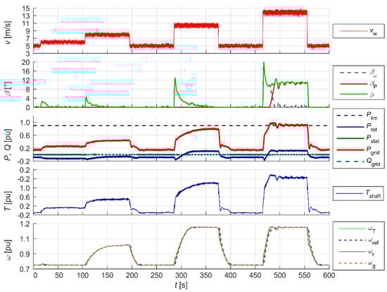
Figure 13.
Wind turbine operation at maximum available power.
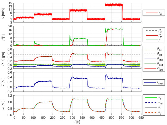
Figure 14.
Wind turbine operation with power limitation Plim.
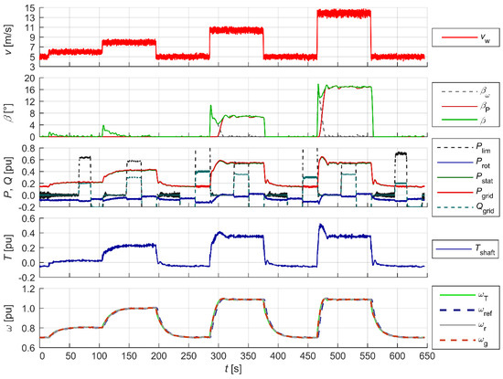
Figure 15.
Wind turbine operation with power limitation Plim with enabled reactive power control.

Figure 16.
Wind turbine operation with power limitation Plim with enabled power factor control cosφ.
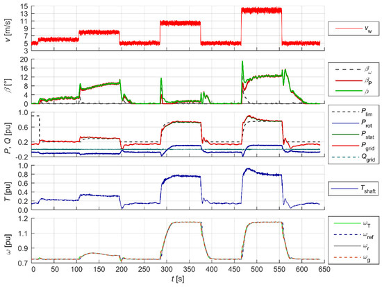
Figure 17.
Wind turbine operation with delta power dP.
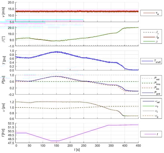
Figure 18.
Wind turbine operation with power limitation with frequency compensation.
- With maximum available (In that mode WT generates maximum available power for current wind speed) power (Figure 13);
- With power limitation (Figure 14);
- With power limitation with enabled reactive power control (Figure 15);
- With power limitation with enabled cosφ power factor control (Figure 16);
- With delta power (Figure 17);
- With power limitation with enabled frequency compensation (Figure 18).
The oscillograms in each figure show the following waveforms recorded during the tests in different operating modes:
- (a)
- Of the wind speed vw, pitch angle of the blades β, and its components from the speed controller βω and the power limiter βP—the top oscillogram;
- (b)
- Of the rotor active power Prot, stator active power Pstat and the power incoming to the grid Pgrid and stator reactive power Qstat—the middle oscillogram;
- (c)
- Of the driving torque on the shaft Tshaft, the angular velocity of the turbine rotor ωT, the generator rotor ωg and the pre-set angular velocity ωref from the MPPT—the bottom oscillogram.
In addition, Figure 18 shows the fourth oscillogram with the waveform of the following:
- (d)
- Grid frequency fgrid.
The active power and angular velocity waveforms show the correct operation of the two basic control systems in the modes tested. The blade pitch angle controller limited the generated power to the pre-set value within the accepted acceptable range (0.2–0.9 p.u.), which can be seen in the β angle waveforms. The generator rotor angular velocity ωg was maintained within the acceptable range (0.7–1.2 p.u.) by means of appropriate active power loading (Pstat). The Pest waveform represents the estimated achievable active power for the measured wind speed, which is used in the delta power control mode dP (Figure 17). Figure 15 and Figure 16 show the operation of the reactive power controller operating independently of the power and speed controllers. The operation of the reactive power controller in two modes is shown: reactive power control (Figure 15) and cosφ power factor control (Figure 16). The reactive power control worked within the rated apparent power of the generator. Figure 18 shows the operation of the WT in reduced and increased grid frequency states. At the elevated grid frequency, the WT limited the generated power in accordance with the characteristics pre-set for the controller; at reduced grid frequency, the WT, as long as it operated in power-limited (Plim), or delta power control (dP) mode, had the ability to have a voltage-raising effect by increasing the generated power in accordance with the characteristics pre-set for the controller within the range achievable for a given wind speed.
5.6. Effects of Inertia and Electrical Parameters on Model Accuracy
The accuracy of the model was investigated in regard to the effects of the inertia of the rotating elements of the SWTE machine unit, the modelled wind turbine, and the electrical parameters. Figure 19 shows the waveforms of selected simulation variants utilising the validation model. A step change in load—a short-circuit disturbance in the 110 kV network lasting 0.1 s (Figure 19a,b) and a step change in the mechanical torque on the shaft lasting 0.1 s (Figure 19a,b)—were pre-set. The simulation model ignored the operation of the FRT (fault ride through) system and abstracted from the physical possibility of a momentary loss of drive torque. The magnitude of the resulting voltage collapse could pose a risk to the converter, which was ignored in the dynamic tests. The waveforms observed were the mechanical torque Tsh, electromagnetic torque Tem, generator angular velocity ωG, power returned to the grid PG, stator voltage Ustat of the reference model FW, and the model SWTE (Figure 19a,b). A difference in the waveforms of angular velocity, electromagnetic moments, stator power, and power returned to the grid of the compared models was observed. The accuracy of the simulations was evaluated based on the maximum root mean square mapping error calculated over a 100 ms moving window of measurement time in static and slow-moving operating conditions, as well as in transient states during and after disturbances.
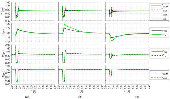
Figure 19.
The waveforms of the shaft mechanical torque Tsh and the shaft electromagnetic torque Tem, the rotor angular velocity DFIM ωG, the generated power PG, and the stator voltage DFIM Ustat of the reference model FW and the model SWTE: (a) reference model (index M) and the same SWTE model (index L), inertia constant HM = HL = 0.96 s—a study of the effect of the electrical parameters of the reference and SWTE models, short circuit in WN dt = 0.1 s; (b) reference model (index M, HM = 0.96 s) and the same model with generators with constant inertia HL = 0.56 s (index L), other generator parameters identical—a study of the effect of constant inertia, short circuit in WN dt = 0.1 s; (c) reference model (index M, HM = 0.96 s) and the same model with generators and with constant inertia HL = 0.56 s (index L), the remaining generator parameters identical—a study of the effect of constant inertia, step change of the mechanical torque on the shaft to zero, dt = 0.1 s.
The waveforms in Figure 19a were recorded when testing the effects of the electrical parameters of the reference model and SWTE, with the same constant inertia of the rotating elements. A difference was observed in the waveform of the electromagnetic moments, which were more oscillatory in the SWTE. In response to a step decrease in voltage, there occurred a step transient increase in SWTE power not present in the reference model waveforms. The rotational speed waveforms overlapped well, with the absolute value of the difference between the two being less than 0.01 in transients as above. The waveforms in Figure 19a,b were recorded when investigating the effect of the rotating elements’ constant inertia on the dynamic properties of the reference model and the SWTE. The comparison shows a clear difference in the rotational speed waveforms. The ratio of the velocity derivatives corresponds to the ratio of the inertia constants. The results obtained for all the tests show that the presented model met the accuracy criterion defined by the condition that the root mean square error of the simulated waveform calculated over a sliding time window of 100 ms did not exceed 5% (IEEE recommendations [52] specified an accuracy of 5% for power system simulation operation as typical). In the wind turbine model, the cumulative error of the measured electrical values (voltage, current, power) was contained in the range of 3–5% in steady-state operation [53].
6. Conclusions
The physical model of the wind turbine presented in this paper significantly develops and improves the solutions presented in the existing literature. The proposed solution features the following key advantages:
- Scalability—it is possible to emulate the operation of both small (single kW), large (tens of MW) wind turbines, and (allowing for some simplifying assumptions) whole wind farms.
- Coherence—the software developed for the model verifies the completeness and adequacy of the digital data provided. In cases of inconsistencies or missing data, the data are corrected and supplemented using an extensive library of data and equations.
- Multifunctionality—the solution presented by the authors facilitates the study and emulation of a wide range of phenomena related to the operation of a wind power plant, from wind-related aspects, through mechanical system elements, to control systems.
- Flexibility—the control algorithms described in this paper have been verified and allow the emulation the operation of a wind turbine(s) with satisfactory accuracy. Since all control algorithms have been implemented in the Simulink Real-Time environment, they can be freely modified, and custom, innovative algorithms can also be implemented.
The model described in this paper allows, among other things, to emulate electrical phenomena that are measurable and physically controllable (e.g., voltages, currents, power, angular velocity of a doubly fed machine). It allows for controlling and observing parameters and state variables of models (turbine, controllers and phenomena) that are only simulated—the environment (e.g., wind speed), the aerodynamic and mechanical part of the turbine (power derived from kinetic energy of the wind, angular velocity of the turbine rotor, shaft torque), and the control algorithms (e.g., angular velocity controllers, power). The modular structure of the digital part facilitates the replacement of any native control system with one’s own and testing its properties over a wide range of parameters. It enables the examination of the impact of specific phenomena on the wind power plant operation individually as well as the effects of their simultaneous (in any configuration) interaction.
Scalable Wind Turbine Emulator combines its advantages with those of other wind turbine simulation and test methods, in particular the flexibility of computer simulations, the use of immanent properties of real electrical devices, the simulation of real electrical waveforms scaled to a power level allowing the study of operation in electrical coupling with emulators or devices of similar power. SWTE is designed for research in laboratories in connection to the power grid in configuration with other devices, real or scaled models of real power equipment. SWTE in configuration with other physical-digital models works well for laboratory tests of smart rids. The choice of the method of implementation of the physical model ensures that the accuracy of simulation of the waveforms with the largest range of parameters of the modelled turbines is optimal in terms of costs, the ability to modify and control the behaviour of the modelled object.
The uniqueness of the presented solution lies in its scalability, despite the use of physical devices with unchangeable parameters. This feature allows for the free shaping of the structure and parameters, and, as a result, it is possible to map both a single wind power plant (of the order of kilowatts or megawatts) and an aggregated wind farm model.
This concept allows for the safe and reproducible testing of the modelled devices, which would not be possible under real conditions due to the threat of damage to the object under test or the difficulty of triggering and controlling the disturbance. The SWTE serves as a suitable and convenient tool for testing new control systems and algorithms for both the WT itself and the master control and protection systems.
Considering the hazards and risks of wind turbine failures posed by field testing, it can be concluded that using the scalable physical model of the wind turbine proposed in this paper is an effective and safe alternative method for testing wind turbines.
Author Contributions
Conceptualisation, R.R. and R.M.; methodology, R.R. and R.M.; software R.R. (model version v21.05 has been used in experiments); validation, R.R. and R.M.; formal analysis, R.R., R.M., B.G., and K.J.; investigation, R.R. and R.M.; writing—original draft preparation, R.R. and R.M.; visualisation, R.R. and R.M.; writing—review and editing, R.R., R.M., B.G., and K.J. All authors have read and agreed to the published version of the manuscript.
Funding
This research received no external funding.
Data Availability Statement
The original contributions presented in this study are included in the article. Further inquiries can be directed to the corresponding author.
Conflicts of Interest
The authors declare no conflict of interest.
Appendix A. List of Symbols
| PG, QG | – | measured active and reactive power |
| Plim | – | active power limit from the power regulator |
| Pref, Qref | – | value of active and reactive power from the speed controller and reactive power controller |
| Pstat, Prot | – | active power of the stator and rotor of the DFIM |
| Pgrid, Qgrid | – | components of active and reactive power returned to the grid |
| Tshaft | – | mechanical torque on the rotor shaft of the generator (simulated) |
| TshM | – | torque on the rotor shaft of the generator of the modelled WT |
| TT | – | torque on the turbine rotor shaft (modelled) |
| vw, vw3p | – | wind speed and wind speed including 3p effect |
| β | – | pitch angle (modelled) |
| βP, βω | – | pitch angle components from power and rotational speed control |
| ωG | – | angular velocity of the generator rotor of the modelled WT |
| ωGL | – | measured shaft speed of the machine unit |
| ωGref | – | pre-set angular velocity of the machine unit generator rotor (ωGref = ωGM) |
| ωref | – | the optimum angular velocity of the WT |
| ωr | – | angular velocity of the SWTE generator rotor |
| ωT | – | angular velocity of the turbine rotor (modelled) |
Appendix B. Method for Determining the Basic Parameters of the Model
Table A1 presents the method for determining the basic parameters of the model. Each step is executed using a statement defining or calculating parameter values.

Table A1.
Methodology for preparing the basic model parameters for SWTE.
Table A1.
Methodology for preparing the basic model parameters for SWTE.
| STEP | PARAMETER | NOTES | ||
|---|---|---|---|---|
| Symbol | Unit | Description | ||
| 1 | Basic parameters | Data normally available | ||
| W | Rated mechanical power of the turbine | |||
| m | Distance of the blade tip from the turbine rotor axis | |||
| m/s | Catalogue value | |||
| m/s | Maximum wind speed of the operating range of the wind turbine | |||
| rpm | Nominal rotational speed of the turbine rotor | |||
| rpm | Minimum operating rotational speed of the turbine rotor | |||
| p.u. | Minimum wind turbine operating range power | |||
| ˚ | Minimum wind turbine rotor blade pitch angle adjustment range angle | 0° | ||
| Hz | Rated grid frequency | |||
| 2 | Adjustable basic parameters | |||
| Interdependent parameters, may be partially available or selected | ||||
| 1 | number of field pole pairs of the DFIM | |||
| m/s | Minimum wind speed of the operating range, wind turbine | |||
| p.u. | Minimum rotor angular velocity of the generator operating range | [p.u.], 0.6–0.7 (a) | ||
| p.u. | Maximum rotor angular velocity of the generator operating range | [p.u.], 1.2–1.3 (a) | ||
| 1 | ~90 (for fn = 50 Hz)/ ~108 (for fn = 60 Hz) | |||
| rad/s | ) | |||
| rad/s | ) | |||
| ° | Maximum angle of the wind turbine rotor blade pitch angle adjustment range | 30° | ||
| 3 | Parameters to be determined | |||
| 1 | Maximum value of the conversion function—maximum efficiency | |||
| 4 | Selection of the conversion factor function | |||
| Conversion factor characteristics are very rarely available for a given WT | ||||
| 1 | For the model to be developed, a characteristic is selected from the available characteristics described in the scientific or technical literature that best fits the assumed parameters. | Conversion factor characteristics are very rarely available for a given WT Table A2: Cp1–Cp12, | ||
| If the conversion factor characteristics are known, then it forms the basis of the calculation and analysis in the following steps performed | ||||
| 5 | Determination of MPP characteristics | Data normally available | ||
| ; | ||||
| MPP | Determination of maximum power point (MPP) curves | (b) | ||
| p.u. | for MPPT module | is the inverse function of MPP | ||
| 6 | ||||
| p.u. | ||||
| m/s | Determination of Rated wind speeds (c) | ; | ||
| m/s | p.u. | |||
| m/s | ||||
| 7 | Selection of the optimum conversion factor function | |||
| . | are satisfactory, go to step 9 | |||
| If the results are satisfactory, GOTO STEP 9 else GOTO STEP 8 | ||||
| 8 | ||||
| and repeat the analysis from step 5. | ||||
| GO TO STEP 5 | ||||
| 9 | Verification/correction | |||
| m/s | Corrected when the power: | |||
| ° | Corrected when | |||
(a) p.u. Referred to: ; (b) MPP—maximum power point (for a given wind speed); (c) —value calculated from the selected characteristics
Appendix C. Wind Power to Mechanical Power Conversion Factor Function
The aerodynamic properties of a turbine are modelled using a two-dimensional power factor function , which is provided by the turbine manufacturer. The function faithfully describes the aerodynamic properties of a turbine with power angle control, and in turbines with power jet detachment control, the function takes the form . The function is a nonlinear function. Numerous variants of the approximation of the shape of the curve describing the power factor function for a three-bladed wind turbine can be found in the literature, with most of the formulae being variants of the general Formula (A1):
Table A2 shows a summary of the conversion factor function formulae used in wind turbine rotor models described in the scientific literature.
Table A2.
Summary of conversion function formulas published in the scientific literature.
Table A2.
Summary of conversion function formulas published in the scientific literature.
| CP Variant | Source | ||
|---|---|---|---|
| Cp5 | [49,54] | ||
| Cp6 | 1 | [49,55] | |
| Cp7 | 1 | [49] | |
| Cp8 | 1 | [55,56] | |
| Cp3 | 1 | [49,57] | |
| Cp9 | 1 | [49,57] | |
| Cp1 | 2 | [58] | |
| Cp10 | 2 | [59,60] | |
| Cp12 | 3 | [61] | |
| Cp2 | [59] | ||
| Cp11 | 4 | [45,48] | |
| Cp4 | Tabulated CP in DigSilent’s PowerFactory programme, | [62,63] | |
| 1 | |||
| 2 | |||
| 3 | |||
| 4 | The coefficients are shown in the Table A3 |
Table A3.
The coefficients of the power function Cp11 from Table A2.
Table A3.
The coefficients of the power function Cp11 from Table A2.
| i | j | αij | i | j | αij |
|---|---|---|---|---|---|
| 4 | 4 | 4.9686 × 10⁻¹⁰ | 2 | 1 | −1.0996 × 10⁻² |
| 4 | 3 | −7.1535 × 10⁻⁸ | 2 | 0 | 1.5727 × 10⁻² |
| 4 | 2 | 1.6167 × 10⁻⁶ | 1 | 4 | −2.3895 × 10⁻⁵ |
| 4 | 1 | −9.4839 × 10⁻⁶ | 1 | 3 | 1.0683 × 10⁻³ |
| 4 | 0 | 1.4787 × 10⁻⁵ | 1 | 2 | −1.3934 × 10⁻² |
| 3 | 4 | −8.9194 × 10⁻⁸ | 1 | 1 | 6.0405 × 10⁻² |
| 3 | 3 | 5.9924 × 10⁻⁶ | 1 | 0 | −6.7606 × 10⁻² |
| 3 | 2 | −1.0479 × 10⁻⁴ | 0 | 4 | 1.1524 × 10⁻⁵ |
| 3 | 1 | 5.7051 × 10⁻⁴ | 0 | 3 | −1.3365 × 10⁻⁴ |
| 3 | 0 | −8.6018 × 10⁻⁴ | 0 | 2 | −1.2406 × 10⁻² |
| 2 | 4 | 2.7937 × 10⁻⁶ | 0 | 1 | 2.1808 × 10⁻¹ |
| 2 | 3 | −1.4855 × 10⁻⁴ | 0 | 0 | −4.1909 × 10⁻¹ |
| 2 | 2 | 2.1495 × 10⁻³ |
References
- Coemans, J.; Maun, J.C. Using the EMTP and the Omicron for developing and testing a transient based digital ground-fault relay far isolated or compensated networks. In Proceedings of the ICDS ‘95. First International Conference on Digital Power System Simulators, College Station, TX, USA, 5–7 April 1995; pp. 265–270. [Google Scholar] [CrossRef]
- Lerch, E.; Ruhle, O. NETOMAC real-time simulator—A new generation of standard test modules for enhanced relay testing. In Proceedings of the Eighth IEEE International Conference on Developments in Power System Protection, Amsterdam, The Netherlands, 5–8 April 2004; pp. 669–674. [Google Scholar] [CrossRef]
- Dolan, D.S.L.; Lehn, P.W. Real-Time Wind Turbine Emulator Suitable for Power Quality and Dynamic Control Studies. In Proceedings of the International Conference on Power Systems Transients (IPST’05), Montreal, QC, Canada, 19–23 June 2005. [Google Scholar]
- dos Santos, T.F.; Chacon, I.V.; de A. Souza, G.C.; de C. A. Pessoa, G.A.P.; Gama, F.O.S.; de A. Teixeira, R.; Salazar, A.O. Wind Turbine Emulator with DC Motor. In Proceedings of the 2019 IEEE 15th Brazilian Power Electronics Conference and 5th IEEE Southern Power Electronics Conference (COBEP/SPEC), Santos, Brazil, 1–4 December 2019; pp. 1–6. [Google Scholar] [CrossRef]
- Chang, L.; Doraiswami, R.; Boutot, T.; Kojabadi, H. Development of a wind turbine simulator for wind energy conversion systems. In Proceedings of the 2000 Canadian Conference on Electrical and Computer Engineering Conference Proceedings, Navigating to a New Era (Cat. No.00TH8492), Halifax, NS, Canada, 6 August 2000; Volume 1, pp. 550–554. [Google Scholar] [CrossRef]
- Lim, C.W. Design and manufacture of small-scale wind turbine simulator to emulate torque response of MW wind turbine. Int. J. Precis. Eng. Manuf -Green Technol. 2017, 4, 409–418. [Google Scholar] [CrossRef]
- Arribas, J.R.; Veganzones, C.; Blazquez, F.; Platero, C.A.; Ramirez, D.; Martinez, S.; Sanchez, J.A.; Martinez, N.H. Computer-Based Simulation and Scaled Laboratory Bench System for the Teaching and Training of Engineers on the Control of Doubly Fed Induction Wind Generators. IEEE Trans. Power Syst. 2011, 26, 1534–1543. [Google Scholar] [CrossRef]
- Li, W.; Xu, D.; Zhang, W.; Ma, H. Research on Wind Turbine Emulation based on DC Motor. In Proceedings of the 2007 2nd IEEE Conference on Industrial Electronics and Applications, Harbin, China, 23–25 May 2007; pp. 2589–2593. [Google Scholar] [CrossRef]
- Li, W.; Yin, M.; Chen, Z.; Zou, Y. Inertia compensation scheme for wind turbine simulator based on deviation mitigation. J. Mod. Power Syst. Clean Energy 2017, 5, 228–238. [Google Scholar] [CrossRef]
- Martínez-Márquez, C.I.; Twizere-Bakunda, J.D.; Lundback-Mompó, D.; Orts-Grau, S.; Gimeno-Sales, F.J.; Seguí-Chilet, S. Small Wind Turbine Emulator Based on Lambda-Cp Curves Obtained under Real Operating Conditions. Energies 2019, 12, 2456. [Google Scholar] [CrossRef]
- Guerrero, J.M.; Lumbreras, C.; Reigosa, D.D.; Garcia, P.; Briz, F. Control and Emulation of Small Wind Turbines Using Torque Estimators. IEEE Trans. Ind. Appl. 2017, 53, 4863–4876. [Google Scholar] [CrossRef]
- Cardenas, R.; Peña, R.; Clare, J.; Asher, G.; Proboste, J. Observers for Sensorless Control of Doubly-Fed Induction Generators. IEEE Trans. Power Electron. 2008, 23, 1075–1084. [Google Scholar] [CrossRef]
- Song, S.H.; Jeong, B.-C.; Lee, H.-I.; Kim, J.-J.; Oh, J.-H.; Venkataramanan, G. Emulation of output characteristics of rotor blades using a hardware-in-loop wind turbine simulator. In Proceedings of the Twentieth Annual IEEE Applied Power Electronics Conference and Exposition, APEC 2005, Austin, TX, USA, 6–10 March 2005; Volume 3, pp. 1791–1796. [Google Scholar] [CrossRef]
- Kojabadi, H.M.; Chang, L.; Boutot, T. Development of a novel wind turbine simulator for wind energy conversion systems using an inverter-controlled induction motor. IEEE Trans. Energy Convers. 2004, 19, 547–552. [Google Scholar] [CrossRef]
- Lopes, L.A.; Lhuilier, J.; Khokhar, M.F.; Mukherjee, A. A Wind Turbine Emulator that Represents the Dynamics of the Wind Turbine Rotor and Drive Train. In Proceedings of the 2005 IEEE 36th Power Electronics Specialists Conference, Dresden, Germany, 6 June 2005; pp. 2092–2097. [Google Scholar] [CrossRef]
- Dufour, C.; Bélanger, J. A Real-Time Simulator for Doubly Fed Induction Generator based Wind Turbine Applications. In Proceedings of the 2004 IEEE 35th Annual Power Electronics Specialists Conference, Aachen, Germany, 20–25 June 2004; Volume 5, pp. 3597–3603. [Google Scholar] [CrossRef]
- Kuffel, R.; Giesbrecht, J.; Maguire, T.; Wierckx, R.P.; McLaren, P. RTDS-a fully digital power system simulator operating in real time. In Proceedings of the IEEE WESCANEX 95, Communications, Power, and Computing, Conference Proceedings, Winnipeg, MB, Canada, 15–16 May 1995; Volume 2, pp. 300–305. [Google Scholar] [CrossRef]
- Moustafa, M.M.Z.; Nzimako, O.; Dekhordi, A. Real time simulation of a wind turbine driven doubly fed induction generator. In Proceedings of the 2017 19th European Conference on Power Electronics and Applications (EPE’17 ECCE Europe), Warsaw, Poland, 11–14 September 2017; pp. P.1–P.10. [Google Scholar] [CrossRef]
- Kouadria, S.; Belfedhal, S.; Berkouk, E.M.; Meslem, Y. Development of real time wind turbine emulator based on DC motor controlled by PI regulator. In Proceedings of the 2013 Eighth International Conference and Exhibition on Ecological Vehicles and Renewable Energies (EVER), Monte Carlo, Monaco, 27–30 March 2013; pp. 1–5. [Google Scholar] [CrossRef]
- Kumsup, S.; Tarasantisuk, C. Real-time wind turbine emulator for testing wind energy conversion systems. In Proceedings of the 2010 IEEE International Energy Conference, Manama, Bahrain, 18–22 December 2010; pp. 7–9. [Google Scholar] [CrossRef]
- Pak, L.; Dinavahi, V. Real-Time Simulation of a Wind Energy System Based on the Doubly-Fed Induction Generator. IEEE Trans. Power Syst. 2009, 24, 1301–1309. [Google Scholar] [CrossRef]
- Lerch, E.; Ruhle, O. Dynamic simulation of DFIGs for wind power plants. In Proceedings of the 2005 International Power Engineering Conference, Singapore, 29 November–2 December 2005; pp. 1–98. [Google Scholar] [CrossRef]
- Chinchilla, M.; Arnaltes, S.; Rodriguez-Amenedo, J.L. Laboratory set-up for wind turbine emulation. In Proceedings of the 2004 IEEE International Conference on Industrial Technology, IEEE ICIT ’04, Hammamet, Tunisia, 8–10 December 2004; Volume 1, pp. 553–557. [Google Scholar] [CrossRef]
- Abo-Khalil, A.G. A new wind turbine simulator using a squirrel-cage motor for wind power generation systems. In Proceedings of the 2011 IEEE Ninth International Conference on Power Electronics and Drive Systems, Singapore, 5–8 December 2011; pp. 750–755. [Google Scholar] [CrossRef]
- Peretti, L.; Särkimäki, V.; Faber, J. A wind turbine emulator for generator control algorithm development. In Proceedings of the 2013 IEEE International Conference on Industrial Technology (ICIT), Cape Town, South Africa, 25–28 February 2013; pp. 228–233. [Google Scholar] [CrossRef]
- Hardy, T.; Jewell, W. Emulation of a 1. In 5MW Wind Turbine with a DC Motor. In Proceedings of the 2011 IEEE Power & Energy Society General Meeting, Detroit, MI, USA, 24–29 July 2011; pp. 1–8. [Google Scholar] [CrossRef]
- Martinello, D.; Carati, E.G.; da Costa, J.P.; Cardoso, R.; Stein, C.M. Emulation of Wind Turbines. In Wind Turbines—Design, Control and Applications; IntechOpen: London, UK, 2016; Available online: https://www.intechopen.com/chapters/50818 (accessed on 1 May 2022). [CrossRef]
- Oh, K.Y.; Lee, J.K.; Bang, H.J.; Park, J.Y.; Lee, J.S.; Epureanu, B.I. Development of a 20 kW wind turbine simulator with similarities to a 3 MW wind turbine. Renew. Energy 2014, 62, 379–387. [Google Scholar] [CrossRef]
- IEC 61400-1:2019; Wind Energy Generation Systems—Part 1: Design Requirements. International Electrotechnical Commission: Geneva, Switzerland, 2019.
- Gan, L.K.; Shek, J.K.H.; Mueller, M.A. Modeling and Characterization of Downwind Tower Shadow Effects Using a Wind Turbine Emulator. IEEE Trans. Ind. Electron. 2017, 64, 7087–7097. [Google Scholar] [CrossRef]
- Lu, L.; Xie, Z.; Zhang, X.; Yang, S.; Cao, R. A Dynamic Wind Turbine Simulator of the Wind Turbine Generator System. In Proceedings of the 2012 Second International Conference on Intelligent System Design and Engineering Application, Sanya, China, 6–7 January 2012; pp. 967–970. [Google Scholar] [CrossRef]
- Manwell, J.F.; McGowan, J.H.; Rogers, A.L. Wind energy explained. In Theory, Design and Application, 2nd ed.; John Wiley & Sons Ltd.: Hoboken, NJ, USA, 2009; ISBN 978-0-470-01500-1. [Google Scholar]
- Dolan, D.S.L.; Lehn, P.W. Simulation Model of Wind Turbine 3p Torque Oscillation due to Wind Shear and Tower Shadow. IEEE Trans. Energy Convers. 2006, 21, 717–724. [Google Scholar] [CrossRef]
- Thiringer, T.; Dahlberg, J.A. Periodic Pulsations from a Three-Bladed Wind Turbine. IEEE Trans. Energy Convers. 2001, 16, 128–133. [Google Scholar] [CrossRef]
- Li, W.; Yin, M.; Zhou, R.; Jiang, M.; Zou, Y. Investigating instability of the wind turbine simulator with the conventional inertia emulation scheme. In Proceedings of the 2015 IEEE Energy Conversion Congress and Exposition (ECCE), Montreal, QC, Canada, 20–24 September 2015; pp. 983–989. [Google Scholar] [CrossRef]
- Gong, B.; Xu, D. Real time wind turbine simulator for wind energy conversion system. In Proceedings of the 2008 IEEE Power Electronics Specialists Conference, Rhodes, Greece, 15–19 June 2008; pp. 1110–1114. [Google Scholar] [CrossRef]
- Liu, B.; Nishikata, S.; Tatsuta, F.; Suzuki, K. A wind turbine simulator considering various moments of inertia using a DC motor. In Proceedings of the 2014 International Symposium on Power Electronics, Electrical Drives, Automation and Motion, Ischia, Italy, 18–20 June 2014; pp. 866–870. [Google Scholar] [CrossRef]
- Neely, J.; Glover, S.; Finn, J.; White, F.E.; Loop, B.; Wasynczuk, O. Wind turbine emulation for intelligent microgrid development. In Proceedings of the 2012 IEEE International Conference on Cyber Technology in Automation, Control, Bangkok, Thailand, 27–31 May 2012, and Intelligent Systems (CYBER); pp. 28–33. [CrossRef]
- Zhangang, Y.; Yanbo, C.; Chengshan, W. Construction, operation and control of a laboratory-scale microgrid. In Proceedings of the 2009 International Conference on Sustainable Power Generation and Supply, Nanjing, China, 6–7 April 2009; pp. 1–5. [Google Scholar] [CrossRef]
- Cardenas, R.; Pena, R. Sensorless vector control of induction machines for variable-speed wind energy applications. IEEE Trans. Energy Convers. 2004, 19, 196–205. [Google Scholar] [CrossRef]
- do Nascimento, T.F.; Nunes, E.A.D.F.; Villarreal, E.R.L.; Pinheiro, R.F.; Salazar, A.O. Performance Analysis of an Electromagnetic Frequency Regulator under Parametric Variations for Wind System Applications. Energies 2022, 15, 2873. [Google Scholar] [CrossRef]
- Hussain, J.; Mishra, M.K. Design and development of real-time small-scale wind turbine simulator. In Proceedings of the 2014 IEEE 6th India International Conference on Power Electronics (IICPE), Kurukshetra, India, 8–10 December 2014; pp. 1–5. [Google Scholar] [CrossRef]
- Han, S.G.; Yu, I.K.; Park, M. PSCAD/EMTDC-based simulation of wind power generation system. Renew. Energy 2007, 32, 105–117. [Google Scholar] [CrossRef]
- Małkowski, R.; Jaskólski, M.; Pawlicki, W. Operation of the Hybrid Photovoltaic-Battery System on the Electricity Market—Simulation, Real-Time Tests and Cost Analysis. Energies 2020, 13, 1402. [Google Scholar] [CrossRef]
- Miller, N.W.; Sanchez-Gasca, J.J.; Price, W.W.; Delmerico, R.W. Dynamic Modeling of GE 1.5 and 3.6 MW Wind Turbine-Generators for Stability Simulations. In Proceedings of the IEEE Power Engineering Society General Meeting, Toronto, ON, Canada, 13–18 July 2003. [Google Scholar] [CrossRef]
- Pena, R.; Clare, J.C.; Asher, G.M. Doubly fed induction generator using back-to-back PWM converters and its application to variable-speed wind-energy generation, Electric Power Applications. IEE Proc. 1996, 143, 231–241. [Google Scholar] [CrossRef]
- Akhmatov, V. Variable-Speed Wind Turbines with Doubly-Fed Induction Generators, Part I: Modelling in Dynamic Simulation Tools. Wind. Eng. 2002, 26, 85–108. [Google Scholar] [CrossRef]
- Clark, K.; Miller, N.W.; Sanchez-Gasca, J.J. Modeling of GE Wind Turbine-Generators for Grid Studies, Technical Report version 4.5; General Electric International: Schenectady, NY, USA, 2010. [Google Scholar]
- Gawarkiewicz, R.; Wasilczuk, F.; Wasilczuk, M. Drivetrain of a Wind Turbine. Mach. Dyn. Res. 2015, 39, 83–95. [Google Scholar]
- Girsang, I.P.; Dhupia, J.S.; Muljadi, E.; Singh, M.; Pao, L.Y. Gearbox and drivetrain models to study dynamic effects of modern wind turbines. In Proceedings of the 2013 IEEE Energy Conversion Congress and Exposition, Denver, CO, USA, 15–19 September 2013; pp. 874–881. [Google Scholar] [CrossRef]
- Taherian-Fard, E.; Sahebi, R.; Niknam, T.; Izadian, A.; Shasadeghi, M. Wind Turbine Drivetrain Technologies. IEEE Trans. Ind. Appl. 2020, 56, 1729–1741. [Google Scholar] [CrossRef]
- IEEE Std 399-1997; IEEE Recommended Practice for Industrial and Commercial Power Systems Analysis. IEEE: Piscataway, NJ, USA, 1998.
- Asmine, M.; Brochu, J.; Fortmann, J.; Gagnon, R.; Kazachkov, Y.; Langlois, C.E.; Larose, C.; Muljadi, E.; MacDowell, J.; Pourbeik, P.; et al. Model Validation for Wind Turbine Generator Models. IEEE Trans. Power Syst. 2011, 26, 1769–1782. [Google Scholar] [CrossRef]
- Anderson, P.M.; Bose, A. Stability Simulation of Wind Turbine Systems. IEEE Trans. Power Appar. Syst. 1983, 102, 3791–3795. [Google Scholar] [CrossRef]
- Heier, S. Grid Integration of Wind Energy Conversion Systems; John Wiley & Sons Ltd.: Hoboken, NJ, USA, 1998; ISBN 9780471971436. [Google Scholar]
- Thin, A.; Kyaing, N. Performance Analysis of Doubly Fed Induction Generator Using Vector Control Technique. Int. J. Electr. Comput. Eng. (IJECE) 2015, 5, 929–938. [Google Scholar] [CrossRef]
- Wind Turbine. Implement Model of Variable Pitch Wind Turbine. Available online: https://www.mathworks.com/help/physmod/sps/powersys/ref/windturbine.html (accessed on May 1st, 2021).
- Slootweg, J.; Polinder, H.; Kling, W. Dynamic modelling of a wind turbine with doubly fed induction generator. In Proceedings of the 2001 Power Engineering Society Summer Meeting, PESSM, Vancouver, BC, Canada, 15–19 July 2001; pp. 644–649. [Google Scholar] [CrossRef]
- Devabhaktuni, S.; Kumar, S.V.J. Modeling and Analysis of Wind turbine Driven Self-Excited Induction Generator Connected to Grid Interface with Multilevel H-Bridge Inverter. J. Energy Technol. Policy 2012, 2, 2. [Google Scholar]
- Yoon, G.; Lee, H.; Lee, J.; Yoon, G.G.; Park, J.K.; Kang, Y.C. Optimal Reserve Allocation to Maximize Kinetic Energy in a Wind Power Plant. J. Electr. Eng. Technol. 2015, 10, 709–718. [Google Scholar] [CrossRef]
- Muyeen, S.M.; Tamura, J.; Murata, T. Stability Augmentation of a Grid-Connected Wind Farm—Wind Turbine Modeling; Springer: London, UK, 2009; ISBN 13 978-1848003156. [Google Scholar]
- Hansen, A.D.; Iov, F.; Sørensen, P.E.; Cutululis, N.A.; Jauch, C.; Blaabjerg, F. Dynamic Wind Turbine Models in Power System Simulation Tool DIgSILENT, Risoe-R-1400 ed2; Technical University of Denmark: Roskilde, Denmark, August 2007. [Google Scholar]
- Dynamic Modelling of Doubly-Fed Induction Machine Wind-Generators; Technical Documentation; DIgSILENT GmbH: Gomaringen, Germany, 2003.
Disclaimer/Publisher’s Note: The statements, opinions and data contained in all publications are solely those of the individual author(s) and contributor(s) and not of MDPI and/or the editor(s). MDPI and/or the editor(s) disclaim responsibility for any injury to people or property resulting from any ideas, methods, instructions or products referred to in the content. |
© 2025 by the authors. Licensee MDPI, Basel, Switzerland. This article is an open access article distributed under the terms and conditions of the Creative Commons Attribution (CC BY) license (https://creativecommons.org/licenses/by/4.0/).