Abstract
This study introduced a novel control approach based on fuzzy logic control (FLC) to enhance the frequency regulation capacity of variable-speed wind turbines (VSWTs). The proposed method integrates FLC within droop and inertia control loops. Real-time measurements of the system frequency and the rate of change of frequency (ROCOF) serve as inputs to the FLC, enabling the method to improve the frequency response by VSWTs. In addition, the method employs FLC for pitch angle frequency control, optimizing reserve power for frequency regulation under varying wind speed levels. The innovative aspect of this study lies in the simultaneous application of FLC to pitch angle frequency control and droop/inertia control, leading to the enhanced frequency regulation capability of VSWTs and smoother operation across a range of wind speeds. Compared with traditional methods, the proposed approach provides a comprehensive and effective solution to the challenges associated with frequency regulation in VSWTs. Through simulations across different wind speed scenarios, the proposed control method demonstrated the best performance among various mature methods, highlighting the efficacy of the proposed method on the frequency regulation of VSWTs under different wind speeds. This study’s findings highlight the potential of the proposed FLC-based method to optimize frequency regulation and contribute to more reliable and efficient wind energy systems.
1. Introduction
Wind energy is rapidly growing globally; the United States aims for a 20% share of wind energy by 2030, while Canada achieved 2 GW by 2008, and is progressing toward a 20% target by 2025 [1]. To meet the energy and climate goals in the EU, the EU Commission issued a specific strategy for developing offshore renewable energy in 2020 [2]. This strategy outlined concrete measures to facilitate the long-term sustainable development of offshore wind, with targets of achieving a minimum installed capacity of 60 GW by 2030 and 300 GW by 2050 [3]. Irish regulators caution about potential stability issues when wind plants contribute to 60–70% of the total instantaneous power generation [4,5,6,7]. That is, as wind power penetration rises, ensuring system frequency regulation becomes more crucial.
The frequency support function of a VSWT falls into two main categories: power reserve control [8,9,10] and inertial control [11,12,13,14]. The former extracts reserved power through de-loading control to support continuous frequency control, and the later releases stored kinetic energy (SKE) in response to the initial time of a disturbance. The utilization of power reserve control faces economic challenges, as it prevents VSWTs from operating with the maximum power point tracking (MPPT). Additionally, the reserve power from VSWTs can be stored in energy storage systems, which incurs extra costs. However, the operating cost of this method is high, and its economic benefit is low [15,16]. Consequently, the practical application of power reserve control in existing wind farms is infrequent.
References [17,18] propose de-loading controls by adjusting the pitch angle, which will reduce the controller’s life and raise maintenance costs. Several references [16,19,20] have suggested fixed de-loading percentages. Reference [21] recommends a control method for the operation of wind turbines by maintaining a power reserve. In [8], an alternative method is proposed to create a spinning reserve by VSWTs, which operates at a low set-point torque; if additional reserve is required, the set-point torque is increased. This approach, however, has its limitations at high wind speeds and the inability to respond to positive frequency changes. Previous studies noted that maintaining constant de-loading can enhance the primary frequency regulation, but it lacks guidance on selecting an appropriate de-loading percentage [22,23]. Furthermore, the fuzzy logic control (FLC) was applied in the pitch angle control. Reference [24] proposes the FLC-PI pitch angle controller. Both the mentioned paper [24] and our paper discuss the control strategies for wind turbine systems using FLC, but they focused on different aspects. The key difference lies in the control focuses, where [24] focused on smoothing performance DFIG wind turbine operation utilizing FLC pitch angle control, while this study aimed to enhance the frequency regulation of VSWTs.
To enhance the performance of frequency regulation of VSWTs, various hybrid control approaches have been proposed [13,25,26,27,28]. For instance, a combination of droop and virtual inertia control loops within the rotor-side converter (RSC) of VSWTs is suggested in [11,15,16,29,30]. References [31,32] combined the real-time pitch angle control with inertia and droop control loops to achieve power reserve control. Reference [27] applied power reserve control using variable coefficient rotor kinetic energy control, which can dynamically adjust real-time coefficients based on the inertial energy and reserve power of VSWTs. In addition to frequency-based inertial control, there exists another method called stepwise inertial control (SIC), which is capable of rapidly increasing the output power of VSWTs and maintaining the power reference for a predetermined curve at the early stage of frequency regulation [33,34,35,36,37]. Additionally, FLC is a widely utilized technique in wind power systems [38,39,40,41]. In [42], FLC was employed to design the adaptive control at the rotor-speed recovery stage when VSWTs implement frequency regulation control, which enhances the frequency control in power systems.
Pitch angle control frequency regulation emulates the governor control of a synchronous generator, limiting active power below nominal values. This approach allows for a change in the active power reserve by adjusting the pitch angles. An adaptive pitch angle control was proposed in [43], and its design considers initial pitch angle manipulation with a look-up table for different wind speed regions. However, this control relies on accurate wind speed measurements, making it challenging to estimate the de-loading percentage during a rapid wind speed change. To eliminate an inaccurate operation by using a look-up table, FLC was applied in de-loading control to optimize the active power reserve for frequency regulation [44,45,46,47]. In addition, references [46,47] applied FLC to the frequency regulation of VSWTs, which aims to optimize the reserve power by considering energy storage systems and pitch angle control. However, these FLC studies only considered fixed wind speeds to determine the VSWTs’ reserve power and neglected continuous wind speed fluctuations in reality. Furthermore, the previous FLC studies relied on wind speeds to determine the SKE and de-loading ratio. Hence, an inaccurate wind speed measurement will bring a large error in FLC outputs, especially when a large wind speed variation appears.
Large wind speed variations can occur during the frequency regulation of VSWTs. The research in [48] indicated that a change in wind speed can affect the operation of frequency regulation in VSWTs. The effect of wind characteristics, such as the wake effect, aerodynamic model, and mechanical fatigue, should be also considered to improve the frequency regulation capability. Reference [49] introduces an active power dispatch mechanism (APDM) and a power reference tracking mechanism (PRTM) that accounts for the wake effect in wind farms. Furthermore, a similar hybrid APDM and PRTM approach [49] was proposed to optimize active power regulation from wind farms by considering the wake effect. In [50], the control method combined yaw control with pitch control to track a power reference signal and optimize power sharing. Reference [51] adopted the Jensen model to establish a power optimization model in a wind farm and introduces a droop control strategy with variable coefficients for primary frequency regulation. These papers provide innovative methods to enhance wind farm control and efficiency by considering wake effects, power dispatch, yaw control, and droop control.
However, this paper focuses on electrical power control. Therefore, it does not directly address the recent works related to aerodynamic performance and wake characteristics, including the effects of blade number on aerodynamic performance, wind turbine wake velocity prediction, or flow patterns and forces in different flow conditions. These areas are outside the scope of this paper. However, the above topics provide valuable insights into the complete frequency regulation capability of a VSWT by considering the aerodynamic aspect.
The motivation behind the proposed method was to enhance the efficiency of wind turbines in frequency regulation, contributing to a more robust and sustainable energy infrastructure. The target was to optimize the performance of VSWTs in frequency control, ensuring they can adapt quickly and effectively to changing conditions in the power grid. By making adaptive adjustments based on real-time data, this innovative control strategy enhances the performance of VSWTs and improves the reliability and efficiency of wind energy generation. The method achieves this by using FLC within droop and inertia control loops, as well as for pitch angle frequency control, enabling VSWTs to better regulate frequency under varying wind speed levels. This leads to a more stable and efficient integration of wind energy into the grid and enhances the overall sustainability of renewable energy sources.
Thus, the innovation of this paper includes the integration of FLC into both pitch angle frequency control and droop/inertia control loops, creating a comprehensive strategy for frequency regulation in VSWTs. The designed FLC employs real-time measurements of frequency deviation and the ROCOF, enabling precise and adaptive control responses. Simulations demonstrated that the proposed method outperformed four established approaches, showing superior effectiveness in frequency regulation. By applying FLC simultaneously with multiple control aspects, the proposed method allows for a more resilient and adaptable integration of wind energy into the power system. Additionally, it optimizes active power reserves by adjusting the pitch angle across a broad range of wind speeds, optimizing the reserved SKE for frequency control and ensuring smoother power output under varying conditions.
This paper proposes a novel frequency control method for VSWTs. The main contributions of this study are listed below:
- By integrating pitch angle control with droop and inertia control loops, VSWTs can implement the required frequency control capability.
- The incorporation of FLC into the pitch angle frequency control loop enhances the performance of frequency regulation by VSWTs, ensuring a consistently smooth and stable operation and reducing stress on the blade during pitch angle operation.
- The proposed simplified FLC within the pitch angle frequency control loop effectively overcomes the complexity of traditional FLC calculations, thereby raising the calculation efficiency.
- Through a comprehensive system simulation that encompassed various wind speed scenarios, this study verified the efficacy of the proposed control strategy.
- This paper demonstrates a comparative analysis with contemporary control methods.
In summary, this paper introduces a novel control method designed to address existing challenges in frequency regulation for VSWTs across different wind speed scenarios. By implementing FLC within both inertia droop loops and pitch angle frequency control loops, this study aimed to enhance the frequency regulation capability of VSWTs. The addition of FLC in pitch angle frequency control plays a crucial role in providing the SKE and maintaining the stable operation of VSWTs under various wind speeds. This innovative approach is motivated by the need for more responsive and efficient control methods that can adapt to changing operational conditions, ensuring consistent and reliable power output. The proposed control method demonstrates significant potential to optimize the performance of wind turbines, leading to improved frequency regulation and greater grid stability. As wind energy becomes a more prominent component of the power system, effective control strategies, such as this one, are essential to harnessing its full potential. By providing a more robust and adaptable solution, this study contributes to the advancement of sustainable energy practices and the continued integration of wind power into modern energy grids.
2. DFIG-VSWT Modeling
The dynamic model of a typical DFIG-based VSWT is described in Figure 1. The mechanical power of a VSWT, which represents the relationship between wind speed and the characteristics of the turbine blade, is shown in (1)–(4) [52,53,54]. The mechanical system can be represented by a mass model [53,54].
where Pm is the mechanical power of the VSWT, CP(λ,β) is a function of both the tip speed ratio λ and pitch angle β, A is the swept area of the VSWT’s blade in m2, ρ is the air density of 1.225 kg/m3, v is the wind speed in m/s, and the coefficients c1 to c6 refer to [48,49].
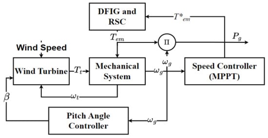
Figure 1.
Schematic representation of the simplified DFIG-VSWT.
To optimize the economic efficiency to capture the maximum wind energy, the speed controller in VSWTs commonly utilizes an MPPT operation [55]. Figure 2 shows the MPPT operation of a DFIG-VSWT based on different rotor speed regions. The curve A–B is the initial zone. In the B–C zone, known as the zone for MPPT operation, the rotor speed is controlled, which ensures the relationship between rotor speed and power follows a specific MPPT curve. From C to D, the rotor speed only changes a little until the power of a VSWT reaches its rated value. Beyond D, pitch angle control takes over the rotor speed control to limit the output power of VSWTs [54].
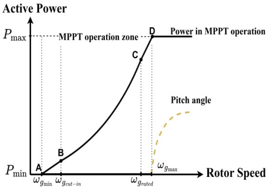
Figure 2.
MPPT curve and pitch angle operating curve.
In high-wind-speed operation, VSWTs must be controlled by the pitch angle control. Figure 3 shows the block diagram of a typical pitch angle controller, where the pitch blades are controlled by pitch servos with hydraulic or electrical systems. In Figure 3, the error in the rotor signal Δωg is the difference between the maximum rotor speed ωg,max and the actual rotor speed ωg,meas. It is sent to a PID controller, and then the PID controller generates the pitch angle reference βref [54,56]. In addition, the servo motor can be represented by a transfer function with a servo time constant Ts for the rotor speed control. The pitch angle actuator model captures the dynamic relationship between the pitch angle reference βref and the initial pitch angle β0.

Figure 3.
Block diagram of a typical pitch angle control.
3. Frequency Regulation by VSWTs
3.1. De-Loading Techniques
Conventional VSWTs are designed for MPPT operation, which would limit their capability in frequency regulation. To resolve it, the de-loading operation was proposed to cooperate with frequency control loops to reserve power for frequency regulation. This ensures a specified reserve Pdeload that is predetermined based on a desired de-loading level. A de-loading level may be restricted between 10 and 20% of rated power, which depends on the constraints for the rotor speed limit, available wind speeds, and converter rating [23]. Under a de-loading operation, the output power of VSWTs is reduced by a predetermined ratio. That is, a de-loading level d% needs to be pre-determined for commercial applications. The de-loading power of a VSWT is calculated by
where Pdeload is the de-loading power, d% is the de-loading level, and PMPPT is the MPPT power. Furthermore, based on the de-loading level d%, the de-loading utilization coefficient Cp,deload is calculated by (6):
To reduce the calculation burden of the de-loading control, refs. [56,57,58] utilized a look-up table to obtain Cp.deload.
The normalized de-loading power Pdeload is calculated by
where kdeload is the magnitude of the de-loading factor, which can be determined by
Typically, VSWTs employ the technique of de-loading through pitch angle control or over-speed operations based on wind speeds. At low wind speeds or rotor speeds that are below the rated value, an over-speed control is preferred for VSWT’s de-loading. At a medium wind speed, an operation that combines over-speeding with pitch angle control is commonly utilized. At a high wind speed, pitch control becomes crucial for power limitation and generator protection, which makes the control more effective than an over-speeding method. In [57], the authors noted that an under-speed and de-loading operation could reduce the performance of VSWTs, posing a threat to mechanical system equilibrium and frequency control.
The pitch angle frequency control in VSWTs can limit the active power below nominal levels by using the β–f droop coefficient. Instead of adjusting the active power directly, the droop coefficient can influence the pitch angle, impacting both the de-loading and frequency response. This method modulates active power reserves by adapting pitch angles against system frequency changes. Figure 4 shows a typical structure of the pitch angle frequency control, where the pitch angle reference is affected by the real-time frequency deviation and the rotor speed measurements.
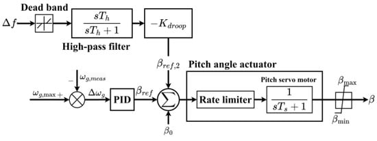
Figure 4.
Pitch angle frequency control.
3.2. Conventional Inertia and Droop Control Loops
The conventional inertia and droop control behave like the frequency response characteristics of a synchronous generator. It uses the real-time ROCOF and frequency deviation measurements to adjust the active power output from VSWTs, which is presented in Figure 5 [11,15,16,29,30].
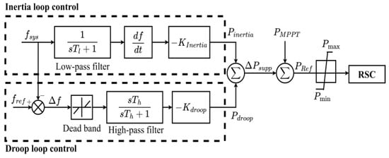
Figure 5.
Conventional inertia and droop control.
The inertia control loop adjusts a VSWT’s power output based on the ROCOF; meanwhile, the droop control loop regulates a VSWT’s power output based on frequency deviation [9,13,51,56,57,58,59,60]. To minimize artificial delays and noise impacts, the corresponding filter should be designed and integrated into the control loop. Combining inertia with droop controls improves a VSWT’s frequency response. Equation (9) represents the supporting active power of a VSWT using inertia and droop control loops.
where KInertia is the inertial gain, which is emulated using the inertia constant of a synchronous generator; Δf is frequency deviation; and KDroop is the droop gain.
3.3. Adaptive Droop Control
The droop controller enables VSWTs to provide additional power for frequency regulation. Furthermore, an adaptive droop coefficient based on the system frequency can optimize the capability of the frequency regulation for VSWTs. For instance, a low coefficient is appropriate for small disturbances because the power deviation from the MPPT point can be minimized, while a high coefficient for significant deviations ensures sufficient power support from VSWTs. A typical adaptive droop control approach is shown in Figure 6. The equation that describes the adaptive droop-gain-based frequency deviation is expressed in (10). Figure 7 represents the function of the adaptive droop coefficient based on the frequency deviation [27,61,62].
where Δfmin and Δfmax are the minimum and maximum dead bands for the frequency control, respectively. Kmin and Kmax indicate the allowable range of the droop gain coefficient; Δf is the frequency deviation; and KDroop is the droop gain.
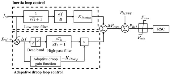
Figure 6.
Frequency-based adaptive droop control [61,62].
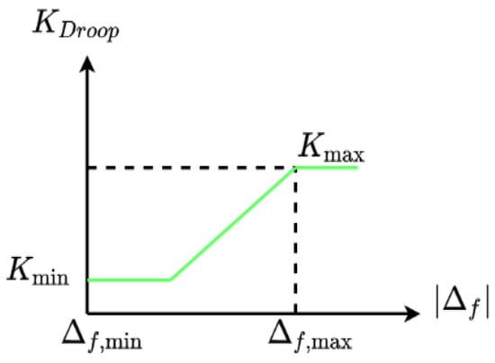
Figure 7.
Adaptive droop control trajectory based on frequency.
Adaptive droop controls may potentially cause a secondary frequency drop by VSWTs due to excessive SKE. It also requires an advanced computation for the droop rate. Using FLC to estimate adaptive droop coefficients should be an appropriate solution. For instance, references [45,63,64,65] applied FLC for the adaptive droop gain, which considers the required reserved power according to wind speeds and de-loading ratios. However, the previous studies provided complex calculations and resulted in slow responses for frequency controls.
Moreover, earlier FLC methods for frequency controls depended on the precise measurement of the wind speed and de-loading ratio, making it difficult to assess the system performance in different operating scenarios. This limitation reduces its overall applicability. The traditional fuzzy rule for the adaptive droop control of VSWTs is listed below and the corresponding control diagram is shown in Figure 8 [63].
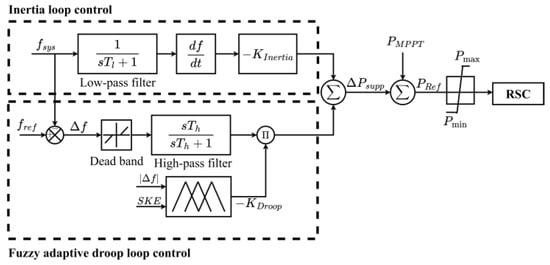
Figure 8.
FLC-based adaptive droop control [63].
- If Δf is significant and the SKE in the VSWTs is minimal, a moderate droop rate is recommended.
- If Δf is substantial and the SKE is significant, the droop rate is large.
- If Δf is small and the SKE is either substantial or minimal, the droop is set to a small value.
The above FLC method requires accurate measurements of wind speeds to determine the SKE. Thus, inaccurate wind speed measurements can cause a large error in both the SKE and droop gain. To improve the performance of the frequency control, wind speed measurements should be avoided.
4. The Proposed Method to Improve Frequency Regulation by VSWTs
Figure 9 shows the flowchart of the proposed method. First, the rotor speed is measured to ensure that the VSWT has enough SKE to provide frequency regulation. If the rotor speed is less than the minimum rotor speed, the VSWT does not participate in frequency regulation. In addition, the system frequency is also measured to determine whether the VSWT should participate in frequency regulation or not.
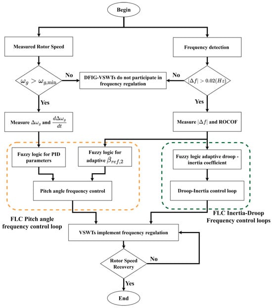
Figure 9.
Flow chart of the proposed method.
Starting from the right side of the flowchart, a VSWT regulates its power output based on the measured system frequency and ROCOF. According to these measurements, the FLC is utilized to determine the appropriate droop and inertia gains.
On the left side of Figure 9, the proposed FLC method utilizes the difference in rotor speed and its rate of change to adjust the PID parameters of the FLC. This guarantees a stable operation of VSWTs, even during a large wind speed change. Meanwhile, the pitch angle frequency control also incorporates FLC to determine the β–f droop gain βref,2, which depends on the system frequency and ROCOF. Therefore, the adjustment of the pitch angle frequency controller can optimize the SKE modulation.
Combining droop and inertia control loops with pitch angle frequency control maximizes the frequency regulation capacity of VSWTs. This is crucial for system stability under varying wind speeds. The control process is complete if the rotor speed begins to recover. With the developed FLC mechanism, VSWTs can help to minimize the negative impacts on the system frequency.
4.1. Adaptive Fuzzy Inertia and Droop Control Loops
Traditional FLCs based on the reserved power of VSWTs highly depend on key factors like wind speeds. Hence, adjusting the control strategy to accommodate the inertia and droop coefficients is difficult. It would potentially lead to an incorrect droop adjustment. In this paper, the proposed adaptive coefficient method takes the frequency deviation and ROCOF as the inputs for the FLC to continuously adjust the inertia and droop gains. Therefore, the operating performance of VSWTs can be improved.
The proposed control method is illustrated in Figure 10, where the ROCOF serves as one of the fuzzy inputs, providing a rapid response to disturbances. It ensures the system’s adaptability to sudden events. The use of the ROCOF as an input enhances the control performance and potentially reduces the computational demands when determining the VSWT reserve power. To avoid signal delays and minimize possible noises, a filter is added in the control loop. Compared with traditional fuzzy adaptive droop controls [44,62,63,64], the proposed method can simplify the implementation of frequency regulation and improve the frequency response of VSWTs.
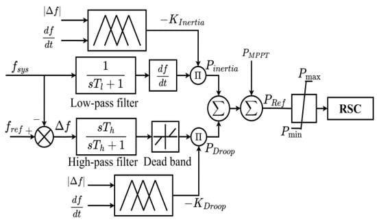
Figure 10.
The proposed fuzzy adaptive inertia and droop control.
The inputs of FLC include the frequency deviation and ROCOF, and Figure 11 and Figure 12 define their membership functions, respectively.
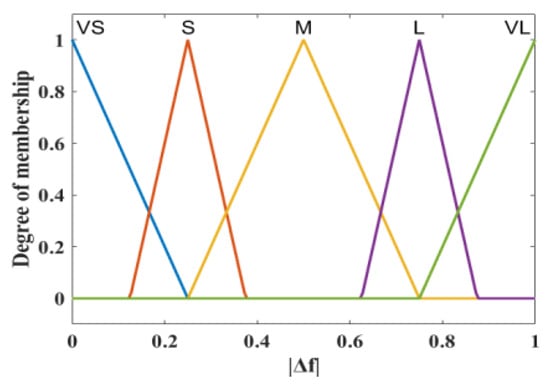
Figure 11.
The designed membership function of |Δf|.
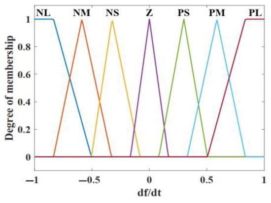
Figure 12.
The designed membership function of the ROCOF.
- Membership function of frequency deviation |Δf|: The fuzzy sets are categorized into very small (VS), small (S), medium (M), large (L), and very large (VL). The frequency deviation |Δf| ranges within [0, 1]. For instance, a unique VL is determined if |Δf| exceeds 0.85 Hz.
- Membership function of the ROCOF: The fuzzy sets are categorized as negative large (NL), negative middle (NM), negative small (NS), negative medium (NM), zero (Z), positive small (PS), positive middle (PM), and positive large (PL). The range of the ROCOF is within [−1, 1] Hz/s. The range of the ROCOF between −1 Hz/s and +1 Hz/s prevents an extreme frequency change that could disrupt the system operations.
The FLC rules for the frequency deviation |Δf| includes five membership functions, while there are seven membership functions for the ROCOF because of its complexity. This setup enables a precise decision in response to various levels of the ROCOF, achieving accuracy and computational efficiency in the control system.
Table 1 shows the fuzzy rule to determine the adaptive droop gain based on the two inputs: |Δf| and ROCOF. The output of the FLC is the droop gain KDroop, which governs the response speed to frequency deviations. It is categorized by seven stages: very slow (VSL), middle slow (MSL), slow (SL), medium (M), fast (F), middle fast (MF), and very fast (VF), which are shown in Figure 13.

Table 1.
Fuzzy rules for the adaptive droop gain.
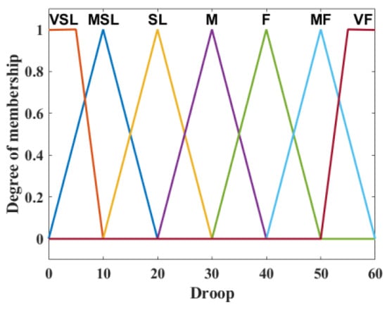
Figure 13.
Designed membership function of adaptive droop gain.
The droop gain is designed based on the allowable released SKE, which prevents the rotor speed from reaching the minimum rotor speed ωmin. Furthermore, it is recommended that the droop gain is equal to or lower than the allowable droop range of synchronous generators in the system, which ensures that VSWTs and synchronous generators can respond to frequency changes in a coordinated manner. This study referred to [26,66,67] when designing the range of the droop gain, which is shown in (11).
Similar to Table 1, Table 2 shows the fuzzy rules to determine the inertia gain KInertia, which is from the output of FLC. It is categorized using five membership functions in Figure 14, namely, small (S), middle small (MS), middle (M), middle large (ML), and large (L). According to [26,66,67], the design of the inertia gain was based on the characteristics of VSWTs. In this paper, the range of the inertia gain is given by (12). If KInertia is too large, the rotor speed of a VSWT may exceed its limit, and then the VSWT will stall. On the other hand, if KInertia is too small, less SKE is released.
where HWTG,eq is the equivalent inertia time constant of the VSWT.

Table 2.
Fuzzy rules for the adaptive inertia gain.
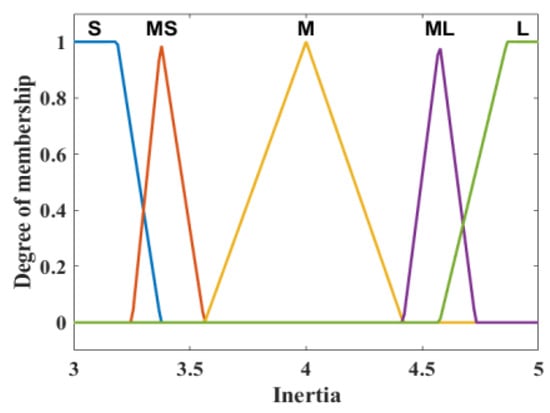
Figure 14.
Designed membership function of adaptive inertia gain.
4.2. Simplified Fuzzy PID Pitch Angle Frequency Control
This study combines a fuzzy PID controller for pitch angle control with an inertia/droop control using an FLC-based PID controller; the control block diagram is shown in Figure 15. The new structure becomes more robust and flexible to generate an appropriate pitch angle. The FLC can adjust the PID parameters according to the signal of the rotor speed difference. According to the specified fuzzy rules shown in Table 3, adaptive PID parameters can be determined to minimize the output error of the pitch angle reference βref under various wind speeds. Thus, the proposed pitch angle control based on the fuzzy PID can be applied for de-loading control under all wind speeds; additionally, the proposed pitch angle control also limits the active power output of a VSWT and its rotor speed under high wind speeds.

Figure 15.
Proposed pitch angle frequency control.

Table 3.
Simplified PID parameters for the pitch angle control.
In the proposed controller, the inputs of FLC include the difference in the rotor speed Δωg and the rate of change of the rotor-speed difference d(Δωg)/dt [46,47]. The membership functions of Δωg and d(Δωg)/dt are shown in Figure 16a and Figure 16b, respectively. The difference means the difference between the rated value and the measured value.

Figure 16.
Membership function of PID controller coefficient. (a) Membership function of Δωg; (b) membership function of d(Δωg)/dt; (c) membership function of PID control coefficients.
The membership function of Δωg or d(Δωg)/dt is categorized with three levels: negative (N), zero (ZE), and positive (P). The outputs of FCL are KP, KI, and KD of the PID controller, and their membership function is shown in Figure 16c, where seven linguistic levels are categorized: positive small (PS), positive medium (PM), positive big (PB), zero (ZE), negative small (NS), negative middle (NM), and negative big (NB).
When Δωg is negative, Kp is reduced, while keeping Ki and Kd relatively stable. A positive d(Δωg)/dt accelerates the reduction of Kp, while a negative d(Δωg)/dt slows down the above process. Conversely, a positive Δωg indicates that the reference signal exceeds the measured value; then, Kp is increased and Kd is decreased to help the observations catch up faster. Additionally, when d(Δωg)/dt is positive, it extends the output error of the pitch angle reference βref, but if d(Δωg)/dt is negative, it requires slowing down the adjustment of Kp to prevent overshooting.
The proposed pitch angle frequency controller also applies the FLC to determine the β–f droop gain βref,2, which maximizes the SKE according to the system frequency. Thus, the combination of fuzzy-based pitch angle frequency and fuzzy-based adaptive inertia–droop controls can maximize the utilization of reserved power from VSWTs for frequency regulation and enhance their frequency control capability.
5. Simulation Results and Discussions
The proposed method was validated on a test system, as shown in Figure 17, which comprised a wind farm with a 10 MW rated power and 15 MW traditional thermal generators. The used VSWTs were DFIG-based wind turbines, whose specifications are shown in Table 4 [55,56]. Additionally, the parameters of a 15 MW thermal generator with a reheat governor and the simplified system are listed in Table 5 [55]. The traditional generator and VSWTs contributed approximately 60% and 40% of the generation to the power load, respectively. The simulation software in this study was the MATLAB version 2024a, the VSWTs and traditional generators in all strategies have the same parameters.
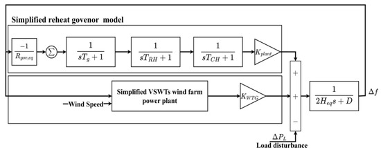
Figure 17.
Block diagram of the test system.

Table 4.
Parameters of DFIG-VSWTs.

Table 5.
Parameters of the reheat governor and power system.
To study the frequency control techniques by VSWTs, the simplified model in Figure 17 was enough to demonstrate the feasibility of the proposed method. It was a modified version of the model in [56,68]. This simplified model focused on the issue of active power and frequency; thus, the related model for reactive power control was eliminated.
It should be noted that references [55,68] were only used for establishing the simplified VSWT model and the power system for simulation. Typically, a frequency regulation control in VSWTs include three control loops (inertia control, droop control, and the MPPT control). Both papers [55,68] applied traditional virtual inertia to manage frequency deviations and improved traditional MPPT strategies by shifting the MPPT curve based on frequency changes. That is, they developed a new MPPT control for frequency regulation to influence the variation in the active power injection. These adjustments aim to control the active power and smooth wind power output to stabilize the system frequency.
However, the objective of this study focused on the integration of FLC in the adaptive inertia and droop control gains, as well as in the pitch angle frequency control loop. Consequently, the proposed method was compared with conventional inertia and droop control loops with constant inertia and droop gains, adaptive droop control methods, and traditional pitch angle frequency control methods to verify the effectiveness of the proposed FLC controller.
This study compared the simulation results from six control scenarios: the proposed control, conventional inertia and droop control, adaptive droop control, fuzzy adaptive droop control, pitch angle frequency control, and the case without control.
For the without-control strategy, the VSWTs operated under the MPPT control mode; thus, they could not support frequency regulation. The conventional inertia and droop control employed fixed controller parameters (KInertia = 5 s and KDroop = 20). This provided a baseline control strategy for frequency regulation but lacked control flexibility. These parameters were selected based on the conclusion in [65,67]. Hence, the parameters were chosen from the various simulations to take the best results that were suitable for the system and the VSWTs. The adaptive droop control was based on (10) and reference [61], which dynamically adjusts the droop gain based on the system frequency aiming to offer a more responsive control approach. The fuzzy adaptive droop control was developed by [63], which incorporates FLC into the controller to adapt droop gain according to real-time conditions, in which the system frequency and the SKE of the VSWTs are used as inputs. Hence, the FLC method can potentially improve the performance of frequency regulation. Both the adaptive droop gain controls and fuzzy adaptive droop control had the same droop gain with the proposed method (from Kdroop-min to Kdroop-max, as shown in Table 4) to ensure a more accurate and meaningful comparison. By aligning the droop gain ranges across these control methods, the comparison was made more consistent, allowing for a fair evaluation of each strategy’s performance under similar operational conditions. The pitch angle frequency control adjusted the wind turbine blade pitch angles to regulate the frequency using a fixed β–f droop gain of 20, as described in [28], and included conventional inertia and droop controllers in the RSC of VSWTs. The proposed control method, which combines FLC with pitch angle frequency control, goes beyond traditional methods by dynamically adjusting pitch angles based on FLC inputs. This approach offers more flexible and adaptive control to respond to changing system conditions, potentially enhancing the frequency regulation performance in VSWTs. Evaluating both adaptive droop control and fuzzy adaptive droop control aims to verify the effectiveness of FLC on frequency control. Additionally, compared with pitch angle frequency control, the proposed FLC can dynamically adjust pitch angles based on the inputs of FLC. This feature enables more flexible and adaptive control to deal with varying system conditions. As a result, it has the potential to improve the performance of frequency regulation from VSWTs.
For all control strategies, VSWTs were de-loaded to reserve a small amount of active power by using pitch angle de-loading control. The comparison in this study was conducted across four distinct wind speed scenarios, as shown in Table 6.

Table 6.
Wind speed scenarios.
5.1. Constant Wind Speed (Below the Rated Value): Vw = 8.4 m/s
In this scenario, the wind speed was 8.4 m/s, and it was assumed that a sudden 10% generation tripped at 5 s. VSWTs initially operate in the MPPT mode. The simulation results from the five control methods are shown in Figure 18 and Table 7.
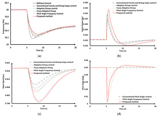
Figure 18.
Simulation results (the Vw = 8.4 m/s scenario). (a) Transient system frequency; (b) the active power of the VSWTs; (c) the rotor speed of the VSWTs; (d) the pitch angle of the VSWTs.

Table 7.
Comparison of simulation results using different frequency control methods when the wind speed was 8.4 m/s.
As can be seen from Table 7 and Figure 18a, in the case of without control, the VSWTs operated in MPPT mode; therefore, the VSWTs did not provide frequency regulation under frequency disturbance. Compared with the without control strategy, the conventional inertia and droop control only helped the system frequency improve a little during the system frequency regulation (frequency nadir raised from 59.177 Hz to 59.217 Hz). In the pitch angle frequency control, by adjusting the pitch angle, the VSWTs could provide more SKE to the frequency disturbance; hence, the frequency nadir could be improved. However, it was still lower than dynamic droop gain control methods. The simulation results describe the effectiveness of the control method for VSWTs that involve dynamically adjusting the droop gain. In terms of the adaptive droop control and the fuzzy adaptive droop control, both methods only focused on the adjustment of the droop gain, which aimed to improve the system frequency performance by providing a faster droop rate. Hence, the frequency nadir was improved (59.525 Hz for adaptive droop control and 59.266 Hz for fuzzy adaptive droop control). However, while these methods focus on adjusting the droop gain and contribute to frequency control in VSWTs, they do not address inertia gain adjustments. This might impact the overall performance of the frequency control. The proposed method with FLC-adaptive inertia and droop gain can provide a faster droop rate and higher inertia gain, which is more suitable to the system disturbance compared with the mature adaptive droop gain controls. Hence, the frequency nadir under the proposed method was improved better than with the other control methods.
The active powers of the VSWTs are illustrated in Figure 18b. The adaptive control method and fuzzy adaptive droop control provided a large amount of supportive power (0.092 pu for the adaptive droop control and 0.096 pu for the fuzzy adaptive droop) due to dynamically adjusting the droop gain to be suitable for the system disturbance. In the case of the proposed method, the supportive power output from VSWTs was the highest compared with the other control methods, where the maximum supportive power was 0.112 pu. This increased initial power output allowed the proposed method to provide substantial SKE support. Additionally, it should be noticed that the potential delays in FLC calculation slowed down the active power responses compared with the mature methods. Furthermore, the method caused a lower rotor speed, but it remained within the safe operational limit (0.7 pu), as shown in Figure 18c. This could cause drivetrain fatigue in the VSWTs.
Additionally, compared with conventional pitch angle frequency control, the proposed method offered a faster and more responsive pitch angle change, with a quicker recovery to the initial pitch angle (Figure 18d). This rapid pitch angle response enabled the VSWTs to provide more SKE for the frequency control, which enhanced the overall system performance. However, the adjustment in the pitch angle for frequency regulation might affect on the mechanical stress, which might reduce the lifespan of the VSWTs.
In summary, the proposed method for dynamically adjusting inertia and droop gains in VSWTs, while simultaneously adjusting pitch angle, demonstrated significant improvements in system frequency performance. These benefits contribute to more effective frequency control and stability in the power grid.
5.2. Constant Wind Speed (Rated Value): Vw = 12 m/s
In this scenario, the wind speed was 12 m/s, and a sudden 10% generation was assumed to trip at 5 s. The simulation results are shown in Figure 19. Since the wind speed was 12 m/s, the rotor speeds of the VSWTs were close to the maximum value, resulting in a higher reserved power in the VSWTs. Consequently, it became efficient for the VSWTs to provide frequency regulation capability.
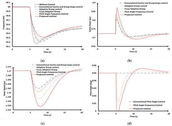
Figure 19.
Simulation results (the Vw = 12 m/s scenario). (a) Transient system frequency; (b) the active power of the VSWTs; (c) the rotor speed of the VSWTs; (d) the pitch angle of the VSWTs.
According to the data presented in Table 8 and Figure 19a, the conventional inertia and droop control could improve the frequency nadir from 59.177 Hz (without control) to 59.221 Hz. Compared with the conventional inertia and droop control, using the adaptive the droop gain, the adaptive droop control improved the frequency nadir to 59.241 Hz. The pitch angle frequency control and the fuzzy adaptive droop control could also improve the frequency regulation due to the higher SKE reserved in the rotating rotor speed (59.243 Hz with the pitch angle frequency control and 59.243 Hz for the fuzzy adaptive droop control). This was because the VSWTs operated under a higher wind speed compared with scenario 1 (8.4 m/s); hence, the VSWTs could reserve more SKE. The proposed method significantly enhanced the SKE for frequency regulation. By adjusting the pitch angle for the frequency regulation and adapting the droop and inertia gain based on the system frequency, this led to a frequency nadir of 59.311 Hz, which was the highest value achieved among all the examined control strategies.

Table 8.
Comparison of the simulation results using different frequency control methods when the wind speed was 12 m/s.
Figure 19b highlights that the proposed method can provide more SKE for frequency regulation. On the other hand, due to the complexity involved in the FLC calculations, the VSWTs experienced a small delayed response compared with the other methods. Furthermore, the use of droop and inertia controls might lead to drivetrain fatigue, which results in a lower rotor speed when compared with other control methods, as shown in Figure 19b.
In the scenario with a high wind speed of 12 m/s, the increased wind speed enabled the VSWTs to deliver more SKE for frequency regulation. At the same time, the pitch angle was significantly reduced to release more SKE for frequency regulation, as demonstrated in Figure 19d. Additionally, the implementation of the proposed FLC adaptive PID controller allowed for a more rapid pitch angle response when a disturbance occurred. This quick reaction further aided in stabilizing the frequency control in dynamic operating conditions. However, the fast adjustment in pitch angle can impact the turbine’s efficiency and shorten the lifespan of turbines.
5.3. Constant Wind Speed (Exceed the Rated Value): Vw = 14 m/s
In this scenario, the wind speed was 14 m/s, and a sudden 10% generation was assumed to trip at 5 s. As wind speed was 14 m/s, the power output of the VSWT reached up to its rated value. Consequently, the power output from the VSWT was effectively limited by controlling the pitch angle of the blades. Despite this limitation, the VSWTs could still contribute a limited amount of SKE, e.g., around 10% of the rated power, to support the frequency regulation. The simulation results are presented and summarized in Figure 20 and Table 9.
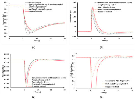
Figure 20.
Simulation results (the Vw = 14 m/s scenario). (a) Transient system frequency; (b) the active power of the VSWTs; (c) the rotor speed of the VSWTs; (d) the pitch angle of the VSWTs.

Table 9.
Comparison of the simulation results using different frequency control methods when the wind speed was 14 m/s.
Figure 20a presents the simulation results for the transient frequency under the scenario of a high wind speed. Given the limitations of the VSWTs, conventional and droop control methods can only provide a small amount of SKE to improve the frequency nadir. Adaptive droop control adjusts the droop gain to better suit the system’s demands, resulting in a more significant improvement in the frequency nadir compared with conventional control methods. At a wind speed of 14 m/s, the VSWTs could store more SKE in the rotating rotor speed, enabling the pitch angle frequency control and fuzzy adaptive droop control to contribute more SKE to the system. The proposed control method adjusted the droop and inertia gains, as well as the pitch angle, allowing the VSWTs to provide more SKE. This led to an increase in the frequency nadir, demonstrating the effectiveness of the proposed method in improving frequency stability.
Figure 20b illustrates that the proposed method enabled the VSWTs to deliver the highest amount of supportive power (0.148 pu). This highlights the success of using FLC for the adaptive inertia–droop control and adjusting the pitch angle to provide more SKE in high-wind-speed conditions. However, due to the complexity of the FLC calculation, the VSWTs has a delay response compared with other methods. The rotor speed dropped more significantly with the proposed method than with the other control strategies, as shown in Figure 20c, indicating its ability to efficiently provide SKE for frequency regulation.
In Figure 20d, through adaptive PID parameters, the new initial pitch angle of 0.85 degrees was set to limit the output power of the VSWTs under a high wind speed. Hence, the amount of reserved power for frequency regulation could be determined, and the pitch angle could be precisely controlled to maximize the allowable SKE in the rotor. This careful management ensures the proposed method enables VSWTs to supply more SKE during high wind speeds, thereby contributing to better frequency regulation and system performance. However, the overuse of the pitch angle could negatively affect the turbine’s efficiency and reduce its operational lifespan.
5.4. Variable Wind Speeds
In this study, testing with wind speed variation alone allowed for a targeted assessment of how control strategies respond to changes in wind power generation. This approach isolated the impact of wind speed fluctuations, which is a major challenge in wind energy systems, providing a clear evaluation of the strategies’ ability to maintain grid stability and regulate frequency.
This scenario aimed to verify the stability of the proposed method for frequency regulation under continuous wind speed changes. This scenario also considered a sudden 10% loss of synchronous generation in the first 10 s. The VSWTs operated under a variable random wind speed from 11 m/s to 7.5 m/s, as shown in Figure 21.
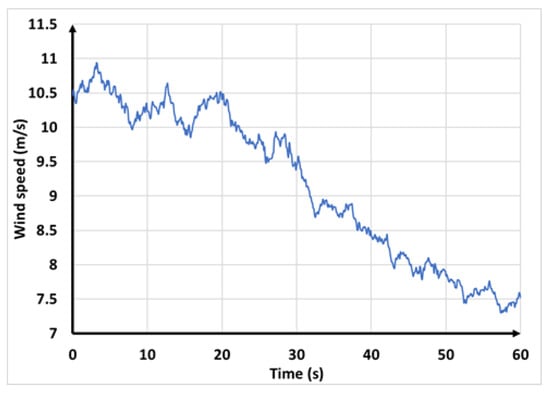
Figure 21.
Wind speed variations.
Figure 22a compares the system frequency response during generator trips under varying wind speeds. When a disturbance occurred at 10 s, the frequency reached its nadir in the first 30 s of the disturbance, as shown in more detail in Figure 22b. Table 10 summarizes the frequency nadir for each control strategy. Without any control, the frequency nadir was 59.125 Hz. Conventional inertia and droop control slightly improved the frequency nadir to 59.224 Hz. Adaptive droop control raised the frequency nadir to 59.234 Hz. Pitch angle frequency control and fuzzy adaptive droop control further enhanced the regulation, achieving frequency nadirs of 59.262 Hz and 59.273 Hz, respectively. The proposed control method, which adjusts droop and inertia gains, along with the pitch angle, allowed the VSWTs to generate more SKE, raising the frequency nadir to 59.3 Hz, which was the highest among all strategies. Hence, these results demonstrate that the proposed FLC method significantly enhanced the frequency nadir, providing a more stable response during fluctuations caused by changing wind conditions.
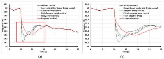
Figure 22.
Simulation system frequency results in variable wind speeds scenario. (a) System frequency; (b) transient system frequency in the first 30 s.

Table 10.
Comparison of frequency nadir using different frequency control methods under various wind speeds.
Figure 23a and Figure 24a compare the active power and rotor speed of the VSWTs under various wind speed scenarios. Additionally, Figure 23b shows the first 30s of disturbance, which highlights that the supportive active power output of the VSWTs using the proposed method surpassed that of the other control methods. This indicates that the proposed control approach allowed for a more efficient and effective use of SKE, resulting in an improved frequency response and greater system stability. Consequently, in the first 30 s, the proposed method led to the lowest rotor speed, as depicted in Figure 24b, reflecting the efficient utilization of SKE for frequency regulation. On the other hand, the use of droop and inertia controls might lead to drivetrain fatigue, potentially affecting long-term reliability and maintenance. Therefore, the interaction between mechanical and electrical components could cause abnormal operation when VSWTs support frequency control.
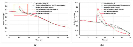
Figure 23.
Simulation of VSWTs active power in variable wind speeds scenario. (a) VSWT’s active power; (b) VSWT’s provided frequency regulation in the first 30 s.
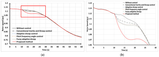
Figure 24.
Simulation of VSWT’s rotor speed in variable wind speeds scenario. (a) VSWT’s rotor speed; (b) VSWT’s rotor speed in the first 30 s.
Figure 25 illustrates the enhancement in the pitch angle response due to the proposed method. By employing the proposed FLC for pitch angle frequency control, the pitch angle was significantly reduced to release more SKE for the frequency, leading to better frequency control. This adjustment enabled the VSWTs to contribute more efficiently to the SKE generation, thereby enhancing their effectiveness in frequency regulation tasks. However, it should be noticed that overuse or improper adjustment for pitch angle can impact the turbine’s efficiency and shorten the lifespan of turbines.
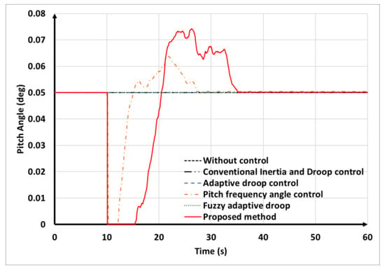
Figure 25.
Simulation of VSWTs pitch angle in variable wind speeds scenario.
6. Conclusions
This study developed a novel FLC-based control method to enhance the frequency regulation capability of VSWTs under different wind speeds. The proposed method integrates FLC into both pitch angle frequency control and droop/inertia control loops, ensuring the maximum utilization of the frequency control capabilities of VSWTs across a diverse wind speed range. To verify the superiority of the proposed method, this study implemented frequency response simulations and compared the results achieved by the proposed method and mature methods. The simulation results demonstrate that implementing the conventional control, adaptive droop control, pitch angle frequency control, fuzzy adaptive droop control, and proposed control can generate reserved SKE to offer frequency support during load and wind speed disturbances. Compared with the traditional methods, the proposed FLC within the droop and inertia control loops utilizes real-time measurements of the frequency deviation and ROCOF to enhance the frequency control during disturbance and wind speed variations. Furthermore, the proposed FLC-based pitch angle frequency control simultaneously adjusts the pitch angle to provide appropriate reserved SKE across a wide range of wind speeds. The proposed method not only effectively provides frequency support during disturbance but also mitigates frequency fluctuations caused by wind speed changes. Through a complete simulation, the proposed method surpassed other mature methods, emphasizing the effectiveness of the proposed method on frequency regulation by VSWTs.
Conversely, the adjustment of the pitch blade angle during frequency regulation and power smoothing may lead to a decrease in mechanical stress. Furthermore, droop and inertia controls might subject the drivetrain to fatigue damage under certain grid conditions. Therefore, it is important to study the mechanical strains in a frequency-regulating wind generator as part of the broader integrated power system dynamics. Furthermore, a promising solution to FLC limitations could be integrating FLC with model predictive control (MPC), creating a hybrid approach that combines immediate control responses with optimized long-term control actions for enhanced performance.
Author Contributions
Conceptualization, B.N.P.; methodology, B.N.P. and Y.-K.W.; data curation, B.N.P.; software, B.N.P.; formal analysis, B.N.P.; investigation, B.N.P.; resources, B.N.P.; writing original draft preparation, B.N.P.; writing—review and editing, Y.-K.W. and M.-H.P.; validation, Y.-K.W. and M.-H.P.; visualization, M.-H.P.; supervision, Y.-K.W.; funding acquisition Y.-K.W.; project administration, Y.-K.W. All authors have read and agreed to the published version of the manuscript.
Funding
This work was financially supported by both National Science and Technology Council (NSTC) of Taiwan under grant NSTC 112-2221-E-194 -005 -MY2 and the Advanced Institute of Manufacturing with High-Tech Innovations (AIM-HI) from the Featured Areas Research Center Program within the framework of the Higher Education Sprout Project by the Ministry of Education (MOE) in Taiwan.
Data Availability Statement
The original contributions presented in the study are included in the article, further inquiries can be directed to the corresponding author.
Conflicts of Interest
The authors declare no conflicts of interest.
References
- Parsons, B.; Milligan, M.; Zavadil, B.; Brooks, D.; Kirby, B.; Dragoon, K.; Caldwell, J. Grid impacts of wind power: A summary of recent studies in the United States. Wind. Energy 2004, 7, 87–108. [Google Scholar] [CrossRef]
- An EU Offshore Renewable Energy Strategy. Available online: https://eur-lex.europa.eu/legal-content/EN/TXT/?uri=COM:2020:741:FIN&qid=1605792629666 (accessed on 24 February 2024).
- Staff Working Document Accompanying the EU Offshore Renewable Energy Strategy—SWD (2020) 273 Final. Available online: https://eur-lex.europa.eu/legal-content/EN/TXT/?uri=SWD:2020:273:FIN&qid=1605792817427 (accessed on 29 February 2024).
- Díaz-González, F.; Hau, M.; Sumper, A.; Gomis-Bellmunt, O. Participation of wind power plants in system frequency control: Review of grid code requirements and control methods. Renew. Sustain. Energy Rev. 2014, 34, 551–564. [Google Scholar] [CrossRef]
- ENTSO-E. Network Code for Requirements for Grid Connection Applicable to All Generators Frequently Asked Questions. Available online: https://www.entsoe.eu/ (accessed on 3 January 2024).
- Euroelectric, 20% Renewables by 2020: A Eurelectric Action Plan, RESAP. Available online: http://www.eurelectric.org/ (accessed on 3 January 2024).
- EirGrid. Eirgrid Grid Code version4.0. Available online: http://www.eirgrid.com (accessed on 3 January 2024).
- Ramtharan, G.; Ekanayake, J.B.; Jenkins, N. Support for spinning reserve from DFIG based wind turbines. In Proceedings of the 2007 International Conference on Industrial and Information Systems, Elk, Poland, 28–30 June 2007; pp. 111–116. [Google Scholar] [CrossRef]
- Lou, W.; Jin, Z.; Zhang, C.; Hou, A.; Wang, W.; Ding, L. Analysis of Primary Frequency Response Based on Overspeed and Pitch Control Reserve and Coordinated Control Strategy. In Proceedings of the 2023 IEEE International Conference on Power Science and Technology (ICPST), Kunming, China, 5–7 May 2023; pp. 193–198. [Google Scholar] [CrossRef]
- Dai, J.; Ding, C.; Zhou, X.; Tang, Y. Adaptive Frequency Control Strategy for PMSG-Based Wind Power Plant Considering Releasable Reserve Power. Sustainability 2022, 14, 1247. [Google Scholar] [CrossRef]
- Morren, J.; de Haan, S.W.H.; Kling, W.L.; Ferreira, J.A. Wind Turbines Emulating Inertia and Supporting Primary Frequency Control. IEEE Trans. Power Syst. 2006, 21, 433–434. [Google Scholar] [CrossRef]
- Itani, S.E.; Annakkage, U.D.; Joos, G. Short-term frequency support utilizing inertial response of DFIG wind turbines. In Proceedings of the IEEE Power and Energy Society General Meeting, Detroit, MI, USA, 24–29 July 2011. [Google Scholar] [CrossRef]
- Dreidy, M.; Mokhlis, H.; Mekhilef, S. Inertia response and frequency control techniques for renewable energy sources: A review. Renew. Sustain. Energy Rev. 2017, 69, 144–155. [Google Scholar] [CrossRef]
- Morren, J.; Pierik, J.; de Haan, S.W.H. Inertial response of variable speed wind turbines. Electr. Power Syst. Res. 2006, 76, 980–987. [Google Scholar] [CrossRef]
- Attya, A.B.; Dominguez-Garcia, J.L.; Anaya-Lara, O. A review on frequency support provision by wind power plants: Current and future challenges. Renew. Sustain. Energy Rev. 2018, 81, 2071–2087. [Google Scholar] [CrossRef]
- Yingcheng, X.; Nengling, T. Review of contribution to frequency control through variable speed wind turbine. Renew. Energy 2011, 36, 1671–1677. [Google Scholar] [CrossRef]
- Chang-Chien, L.-R.; Lin, W.-T.; Yin, Y.-C. Enhancing Frequency Response Control by DFIGs in the High Wind Penetrated Power Systems. IEEE Trans. Power Syst. 2011, 26, 710–718. [Google Scholar] [CrossRef]
- El Mokadem, M.; Courtecuisse, V.; Saudemont, C.; Robyns, B.; Deuse, J. Fuzzy Logic Supervisor-Based Primary Frequency Control Experiments of a Variable-Speed Wind Generator. IEEE Trans. Power Syst. 2009, 24, 407–417. [Google Scholar] [CrossRef]
- Vidyanandan, K.V.; Senroy, N. Primary frequency regulation by deloaded wind turbines using variable droop. IEEE Trans. Power Syst. 2013, 28, 837–846. [Google Scholar] [CrossRef]
- Zertek, A.; Verbic, G.; Pantos, M. A Novel Strategy for Variable-Speed Wind Turbines’ Participation in Primary Frequency Control. IEEE Trans. Sustain. Energy 2012, 3, 791–799. [Google Scholar] [CrossRef]
- Ghosh, S.; Kamalasadan, S.; Senroy, N.; Enslin, J. Doubly Fed Induction Generator (DFIG)-Based Wind Farm Control Framework for Primary Frequency and Inertial Response Application. IEEE Trans. Power Syst. 2016, 31, 1861–1871. [Google Scholar] [CrossRef]
- Zhang, X.; Chen, Y.; Wang, Y.; Zha, X.; Yue, S.; Cheng, X.; Gao, L. Deloading Power Coordinated Distribution Method for Frequency Regulation by Wind Farms Considering Wind Speed Differences. IEEE Access 2019, 7, 122573–122582. [Google Scholar] [CrossRef]
- Pradhan, C.; Bhende, C.N. Adaptive deloading of stand-alone wind farm for primary frequency control. Energy Syst. 2015, 6, 109–127. [Google Scholar] [CrossRef]
- Van, T.L.; Dang, N.K.; Doan, X.N.; Truong, T.H.; Minh, H.N. Adaptive Fuzzy Logic Control to Enhance Pitch Angle Controller for Variable-Speed Wind Turbines. In Proceedings of the 10th International Conference on Knowledge and Systems Engineering (KSE), Ho Chi Minh City, Vietnam, 1–3 November 2018. [Google Scholar]
- Zeng, X.; Liu, T.; Wang, S.; Dong, Y.; Chen, Z. Comprehensive Coordinated Control Strategy of PMSG-Based Wind Turbine for Providing Frequency Regulation Services. IEEE Access 2019, 7, 63944–63953. [Google Scholar] [CrossRef]
- Lee, J.; Muljadi, E.; Sørensen, P.E.; Kang, Y.C. Releasable kinetic energy-based inertial control of a DFIG wind power plant. IEEE Trans. Sustain. Energy 2016, 7, 279–288. [Google Scholar] [CrossRef]
- Wu, Y.-K.; Yang, W.-H.; Hu, Y.-L.; Dzung, P.Q. Frequency regulation at a wind farm using time-varying inertia and droop controls. IEEE Trans. Ind. Appl. 2019, 55, 213–224. [Google Scholar] [CrossRef]
- Chowdhury, B.H.; Ma, H.T. Frequency regulation with wind power plants. In Proceedings of the 2008 IEEE Power and Energy Society General Meeting—Conversion and Delivery of Electrical Energy in the 21st Century, Pittsburgh, PA, USA, 20–24 July 2008; pp. 1–5. [Google Scholar] [CrossRef]
- Abdeen, M.; Sayyed, M.; Dominguez-Garcia, J.L.; Kamel, S. Supplemental Control for System Frequency Support of DFIG-Based Wind Turbines. IEEE Access 2022, 10, 69364–69372. [Google Scholar] [CrossRef]
- Ramtharan, G.; Jenkins, N.; Ekanayake, J. Frequency support from doubly fed induction generator wind turbines. IET Renew. Power Gener. 2007, 1, 3–9. [Google Scholar] [CrossRef]
- Miao, L.; Wen, J.; Xie, H.; Yue, C.; Lee, W.-J. Coordinated Control Strategy of Wind Turbine Generator and Energy Storage Equipment for Frequency Support. IEEE Trans. Ind. Appl. 2015, 51, 2732–2742. [Google Scholar] [CrossRef]
- Tan, J.; Zhang, Y. Coordinated Control Strategy of a Battery Energy Storage System to Support a Wind Power Plant Providing Multi-Timescale Frequency Ancillary Services. IEEE Trans. Sustain. Energy 2017, 8, 1140–1153. [Google Scholar] [CrossRef]
- Ullah, N.R.; Thiringer, T.; Karlsson, D. Temporary primary frequency control support by variable speed wind turbines—Potential and applications. IEEE Trans. Power Syst. 2008, 23, 601–612. [Google Scholar] [CrossRef]
- Yang, D.; Kim, J.; Kang, Y.C.; Muljadi, E.; Zhang, N.; Hong, J.; Song, S.-H.; Zheng, T. Temporary Frequency Support of a DFIG for High Wind Power Penetration. IEEE Trans. Power Syst. 2018, 33, 3428–3437. [Google Scholar] [CrossRef]
- Xu, Y.; Wang, H. Torque Limit-Based Inertial Control of a DFIG for Rapid Frequency Stabilization. Front. Energy Res. 2021, 9, 1–10. [Google Scholar] [CrossRef]
- Kang, M.; Kim, K.; Muljadi, E.; Park, J.-W.; Kang, Y.C. Frequency Control Support of a Doubly-Fed Induction Generator Based on the Torque Limit. IEEE Trans. Power Syst. 2016, 31, 4575–4583. [Google Scholar] [CrossRef]
- Yang, D.; Wang, X.; Yan, G.-G.; Jin, E.; Huang, J.; Zheng, T.; Jin, Z. Decoupling active power control scheme of doubly-fed induction generator for providing virtual inertial response. Int. J. Electr. Power Energy Syst. 2023, 149, 109051. [Google Scholar] [CrossRef]
- Zhang, S.; Mishra, Y.; Shahidehpour, M. Fuzzy-Logic Based Frequency Controller for Wind Farms Augmented with Energy Storage Systems. IEEE Trans. Power Syst. 2016, 31, 1595–1603. [Google Scholar] [CrossRef]
- Xu, M.; Jin, Y.; Ma, J.; Wang, C.; Liu, P. Fuzzy Frequency Droop Control of DFIG Wind Turbine Generators Adapted to Continuous Changes in Wind Speeds. IEEE Access 2023, 11, 115011–115024. [Google Scholar] [CrossRef]
- Shakibjoo, A.D.; Moradzadeh, M.; Din, S.U.; Mohammadzadeh, A.; Mosavi, A.H.; Vandevelde, L. Optimized Type-2 Fuzzy Frequency Control for Multi-Area Power Systems. IEEE Access 2022, 10, 6989–7002. [Google Scholar] [CrossRef]
- Saharia, B.J.; Brahma, H.; Sarmah, N. A review of algorithms for control and optimization for energy management of hybrid renewable energy systems. J. Renew. Sustain. Energy 2018, 10, 053502. [Google Scholar] [CrossRef]
- Peng, X.; Yao, W.; Yan, C.; Wen, J.; Cheng, S. Two-Stage Variable Proportion Coefficient Based Frequency Support of Grid-Connected DFIG-WTs. IEEE Trans. Power Syst. 2020, 35, 962–974. [Google Scholar] [CrossRef]
- Moutis, P.; Loukarakis, E.; Papathanasiou, S.; Hatziargyriou, N.D. Primary load-frequency control from pitch-controlled wind turbines. In Proceedings of the 2009 IEEE Bucharest PowerTech, Bucharest, Romania, 28 June–2 July 2009; pp. 1–7. [Google Scholar] [CrossRef]
- Abazari, A.; Monsef, H.; Wu, B. Load frequency control by de-loaded wind farm using the optimal fuzzy-based PID droop controller. IET Renew. Power Gener. 2019, 13, 180–190. [Google Scholar] [CrossRef]
- Abazari, A.; Dozein, M.G.; Monsef, H.; Wu, B. Wind turbine participation in micro-grid frequency control through self-tuning, adaptive fuzzy droop in de-loaded area. IET Smart Grid 2019, 2, 301–308. [Google Scholar] [CrossRef]
- Civelek, Z.; Lüy, M.; Çam, E.; Barışçı, N. Control of Pitch Angle of Wind Turbine by Fuzzy Pid Controller. Intell. Autom. Soft Comput. 2016, 22, 463–471. [Google Scholar] [CrossRef]
- Sakamoto, R.; Senjyu, T.; Urasaki, N.; Funabashi, T.; Fujita, H.; Sekine, H. Output Power Leveling of Wind Turbine Generators using Pitch Angle Control for All Operating Regions in Wind Farm. In Proceedings of the 13th International Conference on Intelligent Systems Application to Power Systems, Arlington, VA, USA, 6–10 November 2005; pp. 367–372. [Google Scholar] [CrossRef]
- Liu, P.; Jin, Y.; Chen, T.; Shen, X.; Xu, M.; Ju, P. Variation Rule of Wind Speed and Its Influence on the Fast Frequency Response of Wind Turbine Generator. In Proceedings of the 2022 5th International Conference on Renewable Energy and Power Engineering (REPE), Beijing, China, 28–30 September 2022; pp. 345–350. [Google Scholar] [CrossRef]
- Prasad, R.; Padhy, N.P. Active Power Dispatch and Tracking Mechanism for DFIG Wind Turbine Generator in Wind Farm Considering Wake Effect. In Proceedings of the 2022 IEEE International Conference on Power Electronics, Smart Grid, and Renewable Energy (PESGRE), Trivandrum, India, 2–5 January 2022; pp. 1–6. [Google Scholar] [CrossRef]
- Starke, G.M.; Meneveau, C.; King, J.; Gayme, D.F. Yaw-Augmented Control for Wind Farm Power Tracking. In Proceedings of the 2023 American Control Conference (ACC), San Diego, CA, USA, 31 May–2 June 2023; pp. 184–191. [Google Scholar] [CrossRef]
- Wang, S.; Yang, L. Variable Coefficient Droop Control Strategy for Optimal Participation of Wind Farm in Primary Frequency Regulation Considering Wake Superposition Effect. In Proceedings of the 2021 4th International Conference on Energy, Electrical and Power Engineering (CEEPE), Chongqing, China, 23–25 April 2021; pp. 483–488. [Google Scholar] [CrossRef]
- Melicio, R.; Mendes, V.M.F.; Catalao, J.P.S. Modeling and Simulation of Wind Energy Systems with Matrix and Multilevel Power Converters. IEEE Lat. Am. Trans. 2009, 7, 78–84. [Google Scholar] [CrossRef]
- Hardy, T.; Jewell, W. Emulation of a 1.5MW wind turbine with a DC motor. In Proceedings of the 2011 IEEE Power and Energy Society General Meeting, Detroit, MI, USA, 24–29 July 2011; pp. 1–8. [Google Scholar] [CrossRef]
- Clark, K.; Miller, N.W. Modeling of GE Wind Turbine-Generators for Grid Studies Prepared by 2010. Available online: https://www.researchgate.net/publication/267218696 (accessed on 20 December 2023).
- Ochoa, D.; Martinez, S. Fast-Frequency Response Provided by DFIG-Wind Turbines and its Impact on the Grid. IEEE Trans. Power Syst. 2017, 32, 4002–4011. [Google Scholar] [CrossRef]
- Ochoa, D.; Martinez, S. A Simplified Electro-Mechanical Model of a DFIG-based Wind Turbine for Primary Frequency Control Studies. IEEE Lat. Am. Trans. 2016, 14, 3614–3620. [Google Scholar] [CrossRef]
- Janssens, N.A.; Lambin, G.; Bragard, N. Active Power Control Strategies of DFIG Wind Turbines. In Proceedings of the 2007 IEEE Lausanne Power Tech, Lausanne, Switzerland, 1–5 July 2007; pp. 516–521. [Google Scholar] [CrossRef]
- De Almeida, R.G.; Castronuovo, E.D.; Lopes, J.A.P. Optimum Generation Control in Wind Parks When Carrying Out System Operator Requests. IEEE Trans. Power Syst. 2006, 21, 718–725. [Google Scholar] [CrossRef]
- Wu, Z.; Gao, W.; Gao, T.; Yan, W.; Zhang, H.; Yan, S.; Wang, X. State-of-the-art review on frequency response of wind power plants in power systems. J. Mod. Power Syst. Clean Energy 2018, 6, 1–16. [Google Scholar] [CrossRef]
- Li, P.; Hu, W.; Chen, Z. Review on integrated-control method of variable speed wind turbines participation in primary and secondary frequency. In Proceedings of the IECON Proceedings (Industrial Electronics Conference), Florence, Italy, 24–27 October 2016; pp. 4223–4228. [Google Scholar] [CrossRef]
- Jiang, Q.; Zeng, X.; Li, B.; Wang, S.; Liu, T.; Chen, Z.; Wang, T.; Zhang, M. Time-Sharing Frequency Coordinated Control Strategy for PMSG-Based Wind Turbine. IEEE J. Emerg. Sel. Top. Circuits Syst. 2022, 12, 268–278. [Google Scholar] [CrossRef]
- Yang, D.; Jin, Z.; Zheng, T.; Jin, E. An adaptive droop control strategy with smooth rotor speed recovery capability for type III wind turbine generators. Int. J. Electr. Power Energy Syst. 2022, 135, 107532. [Google Scholar] [CrossRef]
- Bubshait, A.; Simoes, M.G. Design of Fuzzy Logic-Based Dynamic Droop Controller of Wind Turbine System for Primary Frequency Support. In Proceedings of the 2018 IEEE Industry Applications Society Annual Meeting (IAS), Portland, OR, USA, 23–27 September 2018; pp. 1–7. [Google Scholar] [CrossRef]
- Chen, J.; Yuan, T.; Li, X.; Li, W.; Wang, X. Research on Coordinated Control Strategy of DFIG-ES System Based on Fuzzy Control. Energies 2023, 16, 4770. [Google Scholar] [CrossRef]
- Zhou, T.; Wang, Y.; Xu, Y. Optimal Stepwise Inertial Control of Wind Turbine Based on Fuzzy Control and Deep Neural Network. In Proceedings of the 2022 IEEE 5th International Electrical and Energy Conference, CIEEC 2022, Nanjing, China, 27–29 May 2022; pp. 4176–4183. [Google Scholar] [CrossRef]
- Keung, P.-K.; Li, P.; Banakar, H.; Ooi, B.T. Kinetic Energy of Wind-Turbine Generators for System Frequency Support. IEEE Trans. Power Syst. 2009, 24, 279–287. [Google Scholar] [CrossRef]
- Holdsworth, L.; Ekanayake, J.B.; Jenkins, N. Power system frequency response from fixed speed and doubly fed induction generator-based wind turbines. Wind. Energy 2004, 7, 21–35. [Google Scholar] [CrossRef]
- Ochoa, D.; Martinez, S. Frequency dependent strategy for mitigating wind power fluctuations of a doubly-fed induction generator wind turbine based on virtual inertia control and blade pitch angle regulation. Renew. Energy 2018, 128, 108–124. [Google Scholar] [CrossRef]
Disclaimer/Publisher’s Note: The statements, opinions and data contained in all publications are solely those of the individual author(s) and contributor(s) and not of MDPI and/or the editor(s). MDPI and/or the editor(s) disclaim responsibility for any injury to people or property resulting from any ideas, methods, instructions or products referred to in the content. |
© 2024 by the authors. Licensee MDPI, Basel, Switzerland. This article is an open access article distributed under the terms and conditions of the Creative Commons Attribution (CC BY) license (https://creativecommons.org/licenses/by/4.0/).