Abstract
Ambient air vaporizers (AVVs) are the most commonly used type of heat exchanger for cryogenic regasification stations. The transfer of heat from the environment for heating the liquefied gas and its vaporization is a cost-free and efficient method. Designing ambient air vaporizers for regasification or fueling stations requires accepting the size and related thermal power of the AVV considering the operating conditions and the type of liquefied gases to be vaporized. The nominal capacity of the ambient air vaporizer depends on its design, the frosting of longitudinal finned tubes, and the airflow through the vaporizer structure. This paper presents the results of experimental studies and computational fluid dynamics (CFD) analysis on determining the heat output of AVV longitudinal finned tubes depending on their design. This experiment was conducted in order to establish a numerical model. The relation between the longitudinal finned tubes thermal power and the air flow velocity is demonstrated and the beneficial effect of forced convection is proved. The obtained results are used for verification calculations of ambient air vaporizers’ performance depending on the size of the AVV, the profile cross-section, and the airflow velocity for different liquefied gases. Under conditions of forced convection, profiles with 12 equal-height fins were discovered to be the most efficient for higher airflow velocity providing up to 7% higher heat rate than profiles with 8 equal-height fins. However, at low air velocity, profiles with 8 equal-length fins showed a comparable heat output to profiles with 12 equal-length fins. Profiles with 8 and 12 unequal high fins differ in average heat output by about 28%. The profile with 12 unequal high fins turned out to be the least effective when 2D airflow was considered in this analysis.
1. Introduction
Liquefied cryogenic gases remain in the liquid phase at very low temperatures, even at atmospheric pressure. However, for several industrial processes and due to a practical aspect like transport or storage the gases are liquefied and compressed under pressure. The transition from gaseous to liquid phase usually occurs at a temperature of about 120 K or lower [1]. Cryogenic fluids commonly used in industry are liquefied natural gas (LNG), liquid oxygen (LOX), liquid nitrogen (LIN), liquid hydrogen (LH2), liquid helium (LHe), and liquid argon (LAr). All specified liquid gases are stored and transported using cryogenically insulated tanks which, due to the high-temperature gradient between the liquid gas and the surrounding air, use cryogenic vacuum insulation systems including perlite, multi-layer MLI insulation or aerogels [2,3,4,5].
Natural gas is mainly liquefied to compress it for transport and storage [6] since the obtained LNG has about 600 times less volume than natural gas in its primary gaseous phase. The boiling point of LNG is 110 K [7]. It is stored at a pressure of 411 bar, depending on the size and type of tank. Liquefied oxygen is used after vaporization in combustion processes requiring an oxygen-enriched atmosphere in the refining, glass, and metallurgical industries. Oxygen can improve combustion by increasing heat transfer, increasing flame temperature, and reducing the volume of flue gases in metal production processes [8]. It is also used in the chemical industry and sewage treatment plants to re-oxygenate water. LOX is usually stored in cryogenic vessels at atmospheric pressure or slight overpressure. The boiling point of liquefied oxygen is 90.2 K [9]. Liquid nitrogen has a lower boiling point, which is 77.2 K. Liquid nitrogen is widely used in many branches of industry and science. LIN is mainly used for metalworking and cooling. After gasification, it is well suited for cutting steel sheets or other metal parts. Furthermore, it is also widely used in the food and medical industries. The boiling point of LH2 is 20 K [10]. Hydrogen is used as fuel in rocket engines, fuel—cell—based power generators, and vehicles. Liquid helium after vaporization is used as a shielding gas in welding processes. It is also used in leak testing of various tanks and installations as well as in the food industry for packaging food under hermetic conditions. The boiling point of liquefied helium is 4 K [11]. Liquefied argon after vaporization has several industrial, research, chemistry, and medical applications. Argon is used in TIG and MIG welding as it is stable, nonflammable, and nontoxic. Argon is an inert gas, which does not oxidize. It is mainly used where the welded material is exposed to oxygen or nitrogen. Argon is also used in a plasma technological process to clean and etch surfaces. The boiling point of liquefied argon is 87.8 K [12]. The other properties of liquefied gases required for calculations in this study are summarized in Table 1.

Table 1.
Properties of liquefied gases.
The vaporization of liquefied gases for their rapid use in the gas phase requires significant heat input. Ambient air vaporizers (Figure 1 and Figure 2) are types of heat exchangers commonly used in cryogenic liquefied gas regasification, storage, or fueling stations to provide the heat required for the process of liquid-to-gas phase transition.
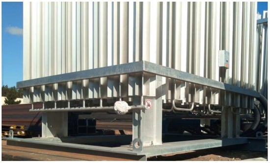
Figure 1.
The ambient air vaporizer with an 8 × 8 array of longitudinal finned tubes.
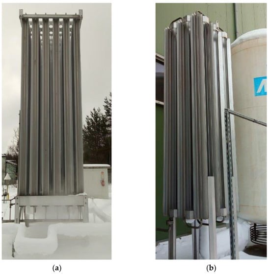
Figure 2.
Examples of ambient air vaporizers: (a) LNG vaporizer with 6 × 6 tubes, (b) Small AAV with 3 × 3 tubes at liquid oxygen storage station.
Depending on the types of liquefied gases for which the vaporizer is designed, the heat demand needed for the evaporation process should be estimated. Design calculations should take into account that less than the total volume of finned pipes contains the product in the same liquid or gas phase. In addition, the determined heat input may be limited by the frosting that occurs on the longitudinal finned tubes during ambient air vaporizer operation. In one of our recent studies [13], we showed by numerical analysis that total frosting of the longitudinal finned tube of the ambient air vaporizer can locally reduce the heat input even up to 70% depending on the fins number.
Other researchers have focused mainly on three problems in previous publications on finned tube heat exchangers. These concerned the formation and effect of frosting on the finned tubes, modeling of heat transfer and operation under various conditions, and optimal AVV design. Concerning the problem of frosting, Seker et al. (2004) [14] presented a mathematical model to determine the thermal characteristics of tubes with transverse fins. In the next article, Seker et al. (2004) [15] compared the results obtained using their previously developed theoretical model of frost formation with experimental studies and they obtained consistent results considering pressure drop and heat transfer coefficients. Hwang and Chao (2014) [16] presented a study on predicting the local frost thickness and local heat transfer rate of a finned tube heat exchanger under standard and high frosting conditions. Chen et al. (2013) [17] developed a model of heat conduction in the frost layer using the fractal method. The authors demonstrated that thermal conductivity is affected not only by density but also depends on frost microstructure and environmental conditions. In contrast, Cheikh and Jacobi (2014) [18] proposed a mathematical model for the prediction of frost thickness and density on a cold flat surface. The model involved new boundary conditions like the total heat flux for the frost—air interface and provided a good match with the experimental results. Benítez and Sherif (2017) [19] applied the orthogonal collocation method to solve equations describing the frost formation process in the case of exposing a cold flat plate to a humidity stream. The authors obtained good consistency between the analytical and experimental results for the prediction of frost parameters such as thickness, temperature, density, or heat flux. Leoni et al. (2017) [20] delivered new experimental data on frost formation on a flat surface of an aluminum plate and compared the results of various predicted methods. The authors included the influence of environmental conditions like air velocity, temperature, and humidity. Kuang and Wang (2015) [21] presented a numerical model to predict the frost parameters and thermal performance of ambient air vaporizers. The authors included the effect of cryogenic fluid flow and the adverse effect of the frost layer. It was demonstrated that during ambient air vaporizer operation, the length of the liquid phase inside the tube decreases and liquid—the gaseous section increases whereas the length of the gaseous phase with vapor decreases. Lee and Choi (2022) [22] implemented to numerical analysis of the frost formation model to investigate the performance of the LNG ambient air vaporizer operating under frost generation conditions. One of the main conclusions was that the ambient air vaporizer consisting of longitudinal finned tubes with 12 fins generated significantly more frost than the one with longitudinal finned tubes with 8 fins.
Regarding heat transfer modeling, Jeong et al. (2008) [23] compared the heat performance of vaporizers with various numbers of fins including different air parameters such as temperature, humidity, and velocity corresponding to different seasons. Jeong et al. (2009) [24] presented the results of CFD analysis of a longitudinal finned vertical tube with liquid nitrogen considered to flow upward. The authors reported heat transfer coefficients inside and outside the tube and provided the formula to calculate the Nusselt number at the outer surface of the longitudinal finned tube. In turn, in the experimental study by Niezgoda—Żelazko and Żelazko (2014) [25], the heat transfer coefficients were determined for longitudinal finned tubes with wavy fins. A change in heat transfer was reported comparing natural convection (V = 0 m/s) and force convection with airflow speed V = 2.3 m/s. As a result, the authors proposed dimensionless relations to determine heat transfer coefficients. Liu et al. (2017) [26] presented three dimensional CFD numerical analysis of coupled heat and mass transfer to verify the performance of a longitudinal finned tube. The authors modeled a complex heat transfer process under the assumptions of a steady—state heat transfer problem and the frost formation was neglected. In a further study, Liu et al. (2016) [27] presented a mathematical model of coupled dynamic heat transfer that considered the formation of frost in cryogenic conditions and the flow of boiling liquefied natural gas. The authors demonstrated that the thermal resistance of frost increased with operation time and the main factor affecting the frost growth was the temperature of the finned tube. Ma et al. (2017) [28] theoretically studied the heat transfer effect of the ambient air vaporizer finned tube. The effect of air temperature, fin length, and number of fins was investigated based on the proposed heat and mass transfer mathematical model. Research was focused on the use of finned tubes in the LNG satellite station. Sun et al. (2018) [29] used the CFD model to study heat transfer in a longitudinal finned tube of LNG ambient air vaporizer under supercritical conditions. The authors first analyzed the regasification process in terms of thermodynamic parameters and validated empirical correlations. Then their model was used to determine operating conditions and compare fins configuration. Wang et al. (2022) [30] developed an analytical model of the coupled heat and mass transfer to predict several basic properties of the frost layer. It was crucial to consider the simultaneous occurrence of the liquid and gaseous phases in different sections of the tube.
Concerning the problems of optimizing the ambient air vaporizer operation, Jeong et al. (2006) [31] presented the numerical analysis of the optimum design of the longitudinal finned tube of the LNG ambient air vaporizer. The authors presented correlations between the thickness of the frost layer and geometric parameters of the finned tube, such as the number of fins or the angle between the fins and the thickness of the fin. Lee et al. (2018) [32] proposed a methodology for robust design of ambient air vaporizer structure based on time series climate data. The study considered decision variables such as fin height, fin thickness, tube radius, and fan capacity. Kopeć and Niezgoda—Zelasko (2021) [33] presented the methodology to determine the optimal dimensions of longitudinal finned tubes with wavy fins for maximizing heat flow. The authors considered mixed convection conditions which were natural convection along the tube and forced convection in a direction transverse to the tube axis. Jadav et al. (2021) [34] presented a study on minimizing the mass of the ambient air vaporizer considering the use of an identical and different number of fins. The authors used a genetic algorithm to solve the optimization problem, which involved continuous 24-hou operation of the AAV containing liquid nitrogen. Considering analysis assumptions, one of the main findings was that tubes with six fins could provide better performance than those with 8 and 12 fins while reducing tube weight. In contrast, Shin et al. (2023) [35] presented a study involving artificial intelligence to optimize the operation of an LNG ambient air vaporizer system consisting of 16 vaporizers. As a result of preliminary research, the authors developed a predictive model to estimate natural gas outlet temperature.
This study focuses on the determination of heat transferred through longitudinal finned tubes under free and forced convection conditions based on CFD analysis. The research methodology is presented in Figure 3. After the problem formulation, the experimental wind tunnel test is carried out using hot water as a liquid product inside the tube with 12 unequal-height fins to establish a numerical model. Then the other cross—sections of longitudinal finned tube profiles are only tested numerically using CFD analysis after the experimental results are found to be consistent with the numerical calculations.
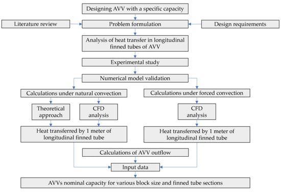
Figure 3.
Diagram of the research methodology.
2. Materials and Methods
2.1. Longitudinal Finned Tube Profiles
Typical cross—sections of longitudinal finned tubes dedicated to ambient air vaporizers consist of a central tube with an inner diameter of about 25–30 mm and fins of equal or different heights placed around the tube. The diameter of the circle described on the highest fins is typically 5 times or more than the diameter of the central pipe to obtain significant surface area for heat transfer. Longitudinal fin tubes for a maximum pressure of about 40 bars are usually made of extruded aluminum. Alternatively, there are also design solutions for higher pressures with an additional steel pipe pressed into the central tube. In this study, five different aluminum longitudinal finned tube profiles are accepted. Cross sections of considered longitudinal finned tubes are shown in Figure 4 and Figure 5. The main dimensions such as the diameters of the circles described on the highest and lowest fins, the diameter of the central tube and wall the thickness are the same for each case according to Figure 4c.
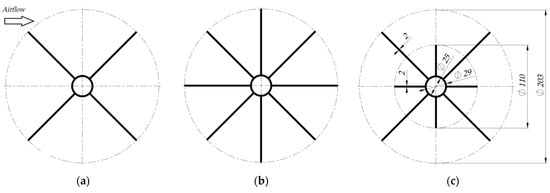
Figure 4.
Cross—sections of longitudinal finned tubes profiles: (a) Profile 4e—with 4 fins of equal height, (b) Profile 8e—with 8 fins of equal height, (c) Profile 8u—with 8 fins of unequal height.
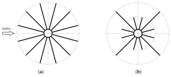
Figure 5.
Cross—sections of longitudinal finned tubes profiles: (a) Profile 12e—with 12 fins of equal height, (b) Profile 12u—with 12 fins of unequal height.
2.2. Analytical Model of Heat Transfer in Longitudinal Finned Tubes
One of our previous papers [13] concerns the analytical and numerical determination of the heat transferred through longitudinal finned tubes under conditions of natural convection and verification of how total frosting of the profile affects the heat decrease. In that study, an analytical model [36] of heat transfer for longitudinal finned tubes of equal fin height is cited, according to which a heat transfer coefficient related to the outer surface of the plane tube is given by Equation (9), which is derived assuming that the temperature gradient (Ti − To) includes three temperature gradients given by Equations (3)–(5). In addition, it is accepted that for the heat transfer in a cylindrical tube, Equations (1) and (2) are valid. Auxiliary diagrams are shown in Figure 6.
where: —the heat [W], —the heat flux through the inner wall of the tube [W/m2], —the heat flux through the outer wall of the tube [W/m2], ri—the inner radius of the central tube [m], ro—the outer radius of the central tube [m], —the tube length.
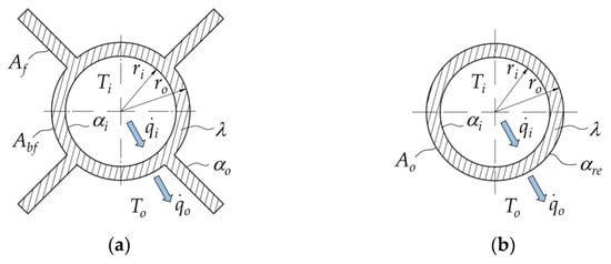
Figure 6.
Auxiliary diagrams for determining heat transfer coefficients: (a) tube with fins; (b) plane tube.
The temperature gradient related to the temperature of liquid Ti and the temperature of the inner wall:
The temperature gradient across the wall thickness:
where: αi—the heat transfer coefficient related to the inner surface of the plane tube [W/(m2K)], αre—the reduced heat transfer coefficient related to the outer surface of the plane tube [W/(m2K)], λ—the thermal conductivity [W/(mK)].
The temperature gradient related to the temperature of the outer wall and the temperature of ambient air To:
where: αre—the reduced heat transfer coefficient related to the outer surface of the plane tube [W/(m2K)].
Finally, the temperature gradient (Ti − To) is obtained as a sum of Equations (3)–(5):
Considering the definition of the heat transfer coefficient related to the outer surface of the plane tube ho, Equation (7) is obtained. Including Equation (7) in Equation (6) results in Equation (8).
Finally, the thermal conductivity coefficient related to the plane tube’s outer surface is determined using Equation (9).
Considering the same height of all fins, the reduced heat transfer coefficient αre is determined using Equation (10). However, the equation can be modified to include fins of two different heights simultaneously in the calculations. Reduced heat transfer coefficient αru referring to the tube with unequal height fins is then obtained from Equation (11).
where: αo—the heat transfer coefficient related to the outer surface of the tube with fins [W/(m2K)], Abf—the outer area between fins [m2], Af—the outer area of fins [m2], Af1—the outer area of lower fins [m2], Af2—the outer area of higher fins [m2], nf1—the number of lower fins, nf2—the number of higher fins, nf—total number of fins.
The efficiency of the fins ηf1 and ηf2 are calculated using Equations (12)–(14).
where: lc1—the height of the lower fins, lc2—the height of the higher fins, s—the fin thickness [mm], m—a fin parameter, l1—an actual height of the lower fins, l2—an actual height of the higher fins.
The heat transferred through the tube with longitudinal fins of unequal height is finally obtained using Equation (15).
where: Q—the heat [W], nf—the total number of fins, Ao—an outer surface area of the tube without fins [m2].
2.3. Calculation of the Gaseous Phase Outflow
The outflow of the gaseous phase from the ambient air vaporizer depends on the amount and rate of evaporation of the liquefied gas contained in all central pipes of longitudinal finned tubes in AVV, which in turn depends on the latent heat of vaporization of liquefied gas. The heat energy required for a state change from liquid to vapor is given by Equation (16). In turn, the outflow of the gaseous phase can be calculated using Equation (17).
where: ml—a mass of liquid to be vaporized [kg], L—the latent heat of vaporization [J/kg], Qp—the heat provided by one meter of longitudinal finned tube length [W], lt—the total length of all finned tubes in the vaporizer [m], lte—an effective length of finned tubes transferred heat from the environment [m], Exp—the expansion ratio, t—time [s], ρ—the density [kg/m3].
2.4. Numerical Simulation
CFD thermal analysis which couples the effects of heat transfer with airflow around the longitudinal finned tube is carried out using ANSYS Fluent 2022 R2 software. First, the k—ω SST turbulence model including the energy equation is adopted and 2D finite volume models are prepared. The adopted mesh quality and boundary conditions are then verified using experimental tests. Finally, all considered profiles are tested using CFD analysis within the range of temperatures depending on the adopted liquefied gas. Calculations are carried out in the range of airflow velocities of 0—5 m/s, which considers the conditions of natural and forced convection.
2.4.1. Governing Equations
ANSYS Fluent solves the mass and momentum equations in each case. The energy equation is additionally solved in the case of the heat transfer problem. The differential equation form of conservation of mass is given by Equation (19). For incompressible flows, the density is assumed to be constant. Accordingly, the conservation of mass equation simplifies to (20). The differential equation for the conservation of momentum and the differential equation for the conservation of energy are given by Equations (21) and (22).
where: ρ—the fluid density; t—the time; ∇—the Nabla operator; —the velocity vector; p—the pressure; µ—the viscosity; —the body force per unit volume; et—the total internal energy; —the viscous stress tensor; λ—the thermal conductivity; —the energy of other processes is not represented in the total energy.
2.4.2. Turbulence Model
The k—ω SST (shear stress transport) turbulence model including the energy equation is adopted since the coupled thermal and airflow problem is considered. This is a two-equation model which solves equations for turbulent kinetic energy (21) and turbulent dissipation rate (22). The k—ω SST model blends k—ε turbulence model in the free stream and the k—ω SST turbulence model near the wall, which allows for a more accurate solution in the entire flow field.
where: k—the turbulent kinetic energy; the specific dissipation rate; the production of k; the production of ; , —the effective diffusivity of k and ω; , —the dissipation of k and ω due to turbulence; —cross diffusion term; , —user-defined source terms; , —buoyancy terms.
2.4.3. Finite Volume Model and Boundary Conditions
Two—dimensional discrete models are adopted for CFD analysis for all of the analyzed longitudinal finned tube cross—sections. The dimensions of the computational domain (Figure 7) correspond to the dimensions of the experimental stand. The width of 250 mm and the length of 500 mm match the diameter and length of the test section. Height is 100 mm which in turn corresponds to the longitudinal finned tube height. A mesh independence test is carried out to determine the element size for the flow field and the cross-section of the finned tube. The geometry of 12 unequal-finned tubes is used in the test. The air velocity is 1 m/s. The result of the mesh independence test is shown in Figure 8. The refinement level 0 refers to the coarse mesh with around 20,000 elements, while level 4 adopted for further analysis, refers to the fine mesh with about 50,000 elements. The inflation layer near the walls is defined for all analyzed cases. In order to appropriately resolve the viscous sublayer near the wall it is required to obtain parameter y + <1 while using the k—ω SST turbulence model.
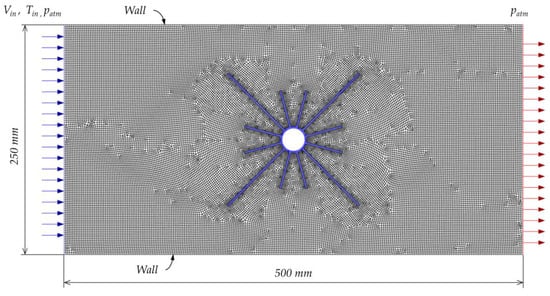
Figure 7.
Model with boundary conditions, where: —the inlet velocity; —the ambient temperature; —atmospheric pressure.
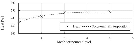
Figure 8.
Results of the mesh independence test.
The following parameters of the inflation layer (Figure 9) are accepted to provide the value of parameter y + <1 for all analyzed cases:
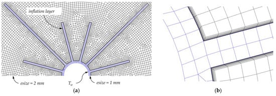
Figure 9.
Mesh: (a) detail around longitudinal fined tube cross-section; (b) inflation layer; where: —the inner wall temperature; —the element size.
- The first layer height: 0.01 mm
- The growth ratio: 1.2
- The number of layers: 10
The following assumptions are made for CFD analysis:
- Analysis type: transient
- CFD solver: pressure—based
- Solver algorithm: SIMPLE
- Air density:
- Air viscosity:
- Turbulence intensity: 5%
- Velocity inlet:
- Atmospheric pressure:
- Ambient temperature:
- Temperature of the inner wall according to the boiling point of the liquefied gas
- Finned tube material: aluminum AW 6061—T6
- AW 6061—T6 thermal conductivity depending on temperature according to [37]
2.5. Experimental Validation
An experimental study is carried out in order to verify the numerical model and boundary conditions accepted for CFD analysis. Experimental tests use a small wind tunnel test stand shown in Figure 10 and Figure 11, which we previously used to determine the aerodynamic drag coefficients of finned tubes [38].
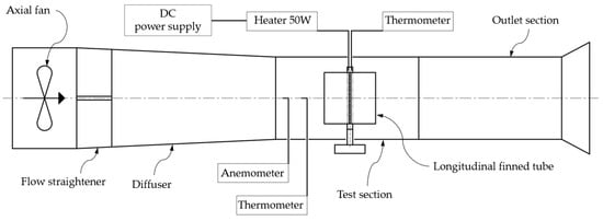
Figure 10.
Schematic diagram of the test stand.
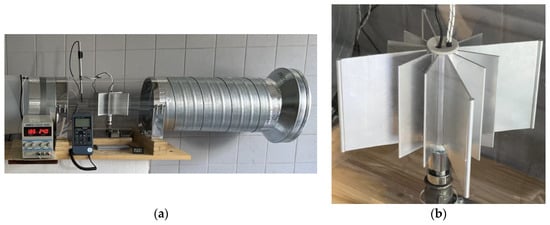
Figure 11.
Experimental test stand: (a) view on the test section; (b) view on the examined profile.
An aluminum longitudinal finned tube with the cross-section in accordance with Profile 12u (Figure 5b) with 12 fins of unequal height is located in the test section. Water is used as a liquid product inside the tube. The water is heated using a 50 W heater located inside the central pipe of the longitudinal finned tube. The heating power of the heater is controlled by the DC power supply by adjusting the current and voltage in order to achieve a power close to the nominal value. The airflow is forced by the 200 W axial fan that can obtain a maximum flow rate of about 3000 m3/h. The fan diameter is 350 mm and the dimensions of the test section are 250 mm in diameter and 500 mm in length. The temperature of the water inside the tube and the temperature of the air flowing in the test section are recorded during the test. A digital anemometer is used to measure air velocity. The air velocity in the range of 0–5 m/s with 1 m/s increments is considered in the tests. The validation results showing the relationship between heat transferred through the tested section of the longitudinal finned tube and air velocity are shown in Figure 12. The average percentage relative error of experimental results compared to CFD results is approximately 5%. Therefore, it is concluded that the adopted numerical model is sufficient for the purposes of this study.
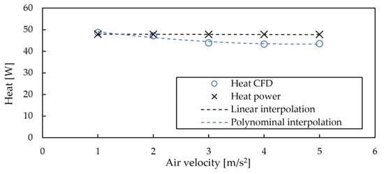
Figure 12.
Validation results.
3. Results and Discussion
The results of the CFD analysis concerning examples of the flow field velocity distribution and the temperature distribution for different longitudinal finned tube profiles are shown in Figure 13, Figure 14 and Figure 15. The presented results refer to the case of forced convection with an airflow velocity of 2 m/s. The temperature of the inner wall of the central tube relates to the boiling point of LNG. The heat Q specified in the figures’ captions refers to the length of one meter of the longitudinal finned tube.
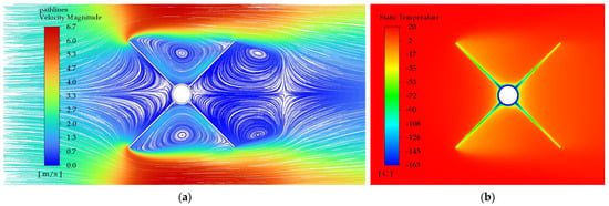
Figure 13.
Profile 4e—with 4 fins of equal height, Vin = 2 m/s, Q = 379 W. (a) Velocity distribution with path lines. (b) Temperature distribution.
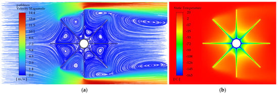
Figure 14.
Profile 8e—with 8 fins of equal height, Vin = 2 m/s, Q = 482 W. (a) Velocity distribution with path lines. (b) Temperature distribution.
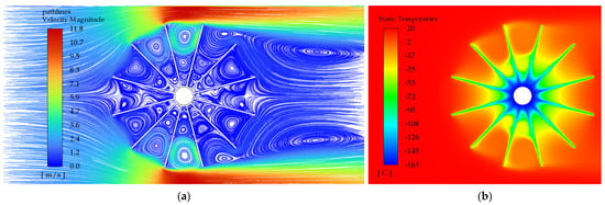
Figure 15.
Profile 12e—with 12 fins of equal height, Vin = 2 m/s, Q = 503 W. (a) Velocity distribution with path lines. (b) Temperature distribution.
Comparing the temperature distribution in the radial direction for Profile 4e (Figure 13b), Profile 8e (Figure 14b), and Profile 12e (Figure 15b) with equal height fins, it can be seen that it is quite comparable. However, for Profile 12e, the zone of the lowest temperatures around the central tube occurs on a much larger diameter, and for Profile 4e it is very small. On the other hand, comparing the flow field velocity distribution for Profile 4e (Figure 13a), Profile 8e (Figure 14a), and Profile 12e (Figure 15a) it can be noticed that for the profiles with 12 equal height fins, there are 3–4 air vortices between the fins in the radial direction, for the profile with 8 equal height fins there are 2 air vortices, while for the profile with 4 equal height fins, there are 1–2 vortices. For the smaller number of vortices between the fins, higher flow velocities near the central pipe and better heat transfer along the entire length of fins are achieved. The most effective heat transfer is therefore for Profile 4e. However, this profile has the smallest external surface area of all the analyzed profiles, which is 0.79 m2 per one meter of the tube length. Therefore, it does not provide the highest heat transfer in this comparison.
Comparing the two most efficient profiles, which are Profile 12e (for which the heat transferred through the outer wall is 503 W) and Profile 8e (for which the heat is 482 W) it can be seen that the difference in the amount of heat is only 4.2%. At the same time, the area of the outer surface of the longitudinal finned tube with a length of one meter and Profile 8e is 1.48 m2, and Profile 12e is 2.18 m2. Thus, the external surface area of the tube with the Profile 12e is 32% larger than that of the tube with the Profile 8e. The amount of heat supplied depends on the heat transfer coefficient, which in turn increases with the increase of the temperature gradient between the outer wall and the air immediately surrounding it. Therefore, despite the much larger external surface of Profile 12e, the amount of heat supplied is only slightly (4.2%) greater than for Profile 8e.
In addition, considering the entire analyzed range of air velocity 0–5 m/s (Figure 18a), it can be noticed that from an economic point of view, it is most advantageous to use Profile 8e with equal fins height, which is less efficient than the Profile 12e mainly in the range of higher air velocity values. The average difference in the amount of heat transferred for the analyzed range of air velocity is 5.4%. The amount of material, which is proportional to the external surface area, is about one-third less for Profile 8e than for Profile 12e.
The comparison of Profile 8u and Profile 12u with unequal fin height reveals a similar relationship regarding temperature distribution. For the profile with 12 unequal height fins the zone of the lowest temperatures around the central tube occurs at a larger diameter than for the profile with 8 unequal height fins. The external surface area of the longitudinal finned tube with a length of one meter and Profile 8e is 1.11m2 while with the Profile 12u is 1.44 m2. Thus, the external surface area of Profile 12u is 23% larger. However, in this case, the amount of heat supplied by the profile with 12 unequal height fins is 31% lower than that supplied by the profile with 8 unequal height fins. The reason for this dependence can be found in the flow field. When analyzing the flow field velocity distribution, it can be seen that for Profile 8u (Figure 16a) there are 1–2 vortices of air in the radial direction, while for Profile 12u (Figure 17a) there are 3–4 vortices, which means that for the profile with 12 unequal fins the warm air is delivered less effectively. Consequently, for profiles with unequal fin heights, the amount of heat transferred is 330 W for Profile 8u and 226 W for Profile 12u. Comparing the above results with the result obtained for the smallest profile with fins of equal height, which is Profile 4e, it can be seen that the amount of transferred heat is 12% lower in the case of Profile 8u and as much as 40% for Profile 12u.
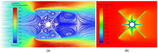
Figure 16.
Profile 8u—with 8 fins of unequal height, Vin = 2 m/s, Q = 330 W. (a) Velocity distribution with pathlines; (b) Temperature distribution.
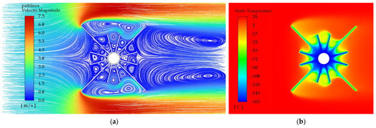
Figure 17.
Profile 12u—with 12 fins of unequal height, Vin = 2 m/s, Q = 226 W. (a) Velocity distribution with pathlines; (b) Temperature distribution.
The results shown in Figure 18 and Figure 19 present CFD-based values of heat transferred through one meter of longitudinal finned tube length with different cross—sections containing liquefied natural gas (Figure 18a), liquid oxygen (Figure 18b), liquid nitrogen (Figure 19a) and liquid helium (Figure 19b). The heat transferred through the longitudinal finned tubes with the analyzed profiles is presented depending on the airflow velocity in the range of 0–5 m/s. It is also verified that the heat values for the case of natural convection calculated on the basis of the analytical model presented in paragraph 2.2 coincide with the numerical results with an average error of less than 2%.
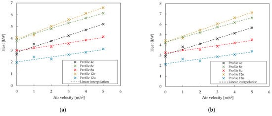
Figure 18.
Heat transferred through the one—meter length profile with (a) LNG, (b) LOX.
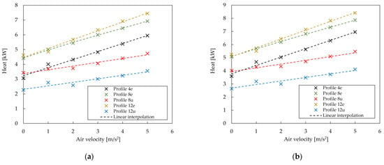
Figure 19.
Heat transferred through the one—meter length profile with (a) LIN, (b) LHe.
It can be seen that under conditions of natural convection, the heat transferred through all considered profiles is significantly lower than under conditions of forced convection. In turn, under conditions of forced convection, the transferred heat depends on the profile geometry and corresponding flow field. Comparing the heat transferred by profiles with fins of equal height as a function of air velocity, a linear relationship can be observed. The performance of profiles with 8 and 12 fins is almost the same for the velocity range of 0–1 m/s. In turn, considering the velocity range 2–5 m/s, the profile with 12 fins is 4–7% more efficient. The heat for the profile with 4 equal height fins related to the air velocity also has a linear correlation. However, for Profile 4e the average heat is 21% lower than for Profile 8e and 25% lower than for Profile 12e. This is due to the much smaller external surface area. Comparing profiles with 8 and 12 unequal height fins it can be noticed that the difference of heat is 28% on average. The profile with 12 fins of unequal height turns out to be the least effective. This is related to the 2D flow field and not, as might be expected, to the external surface area of the longitudinal finned tube. The calculated nominal capacity for selected liquid gases is presented, respectively, in the following figures: liquefied natural gas (Figure 20), liquid oxygen (Figure 21), liquid nitrogen (Figure 22), and liquid helium (Figure 23).
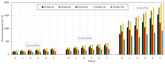
Figure 20.
Nominal capacity for three different sizes of LNG ambient air vaporizers.
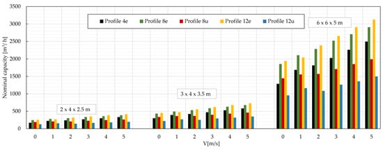
Figure 21.
Nominal capacity for three different sizes of LOX ambient air vaporizers.
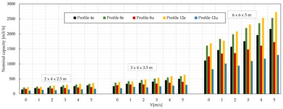
Figure 22.
Nominal capacity for three different sizes of LIN ambient air vaporizers.
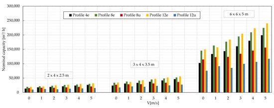
Figure 23.
Nominal capacity for three different sizes of LHe ambient air vaporizers.
The nominal capacity of ambient air vaporizers is calculated using Equation (17) for three configurations of AVV block sizes: 2 × 4 (3 m profile length), 3 × 4 (3.5 m profile length), and 6 × 6 (5 m profile length). The total length of all longitudinal finned tubes in the ambient air vaporizer is, respectively, 24, 42, and 180 m. The effective length of finned tubes is, respectively, 4, 7, and 30 m. The effective length is calculated assuming that 1/6 of the total length of finned tubes contains liquid gas which is vaporized [27].
When comparing the results of the nominal capacity of ambient air vaporizers, a trend can be observed that corresponds to the results of heat transferred through a one—meter—long profile. The nominal efficiency of ambient air vaporizers increases linearly for each size of the vaporizer and each liquid product under consideration when natural or forced convection occurs. For ambient air vaporizers consisting of longitudinal finned tubes with profiles of equal fin height, an average nominal capacity increase of 18% for a 1 m/s increase in air velocity is observed. On the other hand, for ambient air vaporizers consisting of tubes with profiles of unequal fin height, an average nominal capacity increase of 10% per 1 m/s increase in air velocity is noted.
4. Conclusions
The problem of modeling heat flow through longitudinal finned tubes designed for applications in ambient air vaporizers is addressed. An analytical and numerical approach using CFD and experimental validation is presented. The problem of calculating the nominal capacity of vaporizers for various liquefied gases with specific values of the latent heat of vaporization and the expansion ratio is also described. The nominal capacity of sample vaporizer sizes is determined by calculating the outflow of the gaseous phase obtained from the evaporation of the liquid product contained in the longitudinal finned tube sections after supplying the required amount of heat for one hour. CFD numerical analyses are carried out for one—meter—long sections of longitudinal finned tubes with different cross sections and containing different liquefied gases with various boiling points. An experiment using water as a liquid medium is carried out to verify the boundary conditions and the quality of the numerical model. The agreement between experimental and numerical results is obtained with an average error of approximately 5%.
The results show how the amount of heat supplied to vaporize the liquid phase varies with the cross-section of the longitudinally finned tube profiles and how the air velocity flow field affects the heat rate. It is found that considering the 2D flow field the amount of heat transferred through the longitudinal finned tubes strongly depends on the velocity flow field, and less significantly on the external surface area of the longitudinal finned tube. Comparative data is presented that may be useful to the industry when designing ambient air vaporizers.
Considering the overall result for the adopted range of airflow velocity, the best average result is obtained for the use of the profile with 12 equal high fins, which offered the largest heat transfer area, followed by the profile with 8 equal high fins. When comparing the results for the profiles with 12 and 8 equal-length fins under the conditions of natural and forced convection, the average difference is only about 4%.
The profile with 8 fins of equal height is the most advantageous choice from an economic point of view because the amount of material in the cross—section is about one-third less than for the profile with 12 fins of equal height.
Based on calculations, it can be concluded that the difference in the amount of heat supplied by profiles with 8 and 12 unequal height fins is 28% on average. It can be concluded that in the whole range of considered airflow velocities of 0–5 m/s the use of the profile with 8 and 12 unequal height fins provides the worst performance. However, it should be noted that there is a need for further research considering the airflow also in the direction along the longitudinal finned tube axis. This can affect the change in the flow field and the amount of heat supplied both under conditions of natural convection and forced convection, which determines the direction of our further research.
Author Contributions
Conceptualization, F.L. and E.L.; methodology, F.L. and E.L.; software, F.L.; validation, F.L.; formal analysis, F.L. and E.L.; investigation, F.L. and E.L.; resources, E.L.; data curation, F.L.; writing—original draft preparation, F.L.; writing—review and editing, F.L.; visualization, F.L.; supervision, F.L.; project administration, F.L. authors have read and agreed to the published version of the manuscript. All authors have read and agreed to the published version of the manuscript.
Funding
This research received no external funding.
Data Availability Statement
The data is included in the article.
Acknowledgments
This research was carried out with the support of the ANSYS National License coordinated by Interdisciplinary Centre for Mathematical and Computational Modelling University of Warsaw (ICM UW).
Conflicts of Interest
The authors declare no conflicts of interest.
References
- Madana Gopal, J.V.; Morgan, R.; De Sercey, G.; Vogiatzaki, K. Overview of Common Thermophysical Property Modelling Approaches for Cryogenic Fluid Simulations at Supercritical Conditions. Energies 2023, 16, 885. [Google Scholar] [CrossRef]
- Qiu, Y.; Yang, H.; Tong, L.; Wang, L. Research Progress of Cryogenic Materials for Storage and Transportation of Liquid Hydrogen. Metals 2021, 11, 1101. [Google Scholar] [CrossRef]
- Sambucci, M.; Savoni, F.; Valente, M. Aerogel Technology for Thermal Insulation of Cryogenic Tanks—Numerical Analysis for Comparison with Traditional Insulating Materials. Gels 2023, 9, 307. [Google Scholar] [CrossRef] [PubMed]
- Lisowski, E.; Lisowski, F. Study on thermal insulation of liquefied natural gas cryogenic road tanker. Therm. Sci. 2019, 23 (Suppl. 4), S1381–S1391. [Google Scholar] [CrossRef]
- Lisowski, F.; Lisowski, E. Design of internal supports for double—Walled liquefied natural gas road tanker. Heat Transf. Eng. 2021, 8, 238–247. [Google Scholar] [CrossRef]
- Al-Yafei, H.; Kucukvar, M.; AlNouss, A.; Aseel, S.; Onat, N.C. A Novel Hybrid Life Cycle Assessment Approach to Air Emissions and Human Health Impacts of Liquefied Natural Gas Supply Chain. Energies 2021, 14, 6278. [Google Scholar] [CrossRef]
- Banaszkiewicz, T.; Chorowski, M.; Gizicki, W.; Jedrusyna, A.; Kielar, J.; Malecha, Z.; Piotrowska, A.; Polinski, J.; Rogala, Z.; Sierpowski, K.; et al. Liquefied Natural Gas in Mobile Applications—Opportunities and Challenges. Energies 2020, 13, 5673. [Google Scholar] [CrossRef]
- Cheng, Z.; Zhang, P.; Wang, L. Oxygen Demand Forecasting and Optimal Scheduling of the Oxygen Gas Systems in Iron-and Steel-Making Enterprises. Appl. Sci. 2023, 13, 11618. [Google Scholar] [CrossRef]
- Nomura, T.; Matsuda, Y.H.; Kobayashi, T.C. Solid and Liquid Oxygen under Ultrahigh Magnetic Fields. Oxygen 2022, 2, 152–163. [Google Scholar] [CrossRef]
- Aziz, M. Liquid Hydrogen: A Review on Liquefaction, Storage, Transportation, and Safety. Energies 2021, 14, 5917. [Google Scholar] [CrossRef]
- Serra Leal, J.S.; Incer-Valverde, J.; Morosuk, T. Helium: Sources, Applications, Supply, and Demand. Gases 2023, 3, 181–183. [Google Scholar] [CrossRef]
- Sismanoglu, B.N.; Maciel, H.S.; Radmilovic-Radjenovic, M.; Pessoa, R.S. ARGON Production, Characteristics and Applications, 3rd ed.; Nova Publishers Inc.: New York, NY, USA, 2013. [Google Scholar]
- Lisowski, F.; Lisowski, E. Influence of Fins Number and Frosting on Heat Transfer through Longitudinal Finned Tubes of LNG Ambient Air Vaporizers. Energies 2022, 15, 280. [Google Scholar] [CrossRef]
- Seker, D.; Karatas, H.; Egrican, N. Frost formation on fin-and-tube heat exchangers. Part I—Modeling of frost formation on fin-and-tube heat exchangers. Int. J. Refrig 2004, 4, 367–374. [Google Scholar] [CrossRef]
- Seker, D.; Karatas, H.; Egrican, N. Frost formation on fin-and-tube heat exchangers. Part II—Experimental investigation of frost formation on fin-and-tube heat exchangers. Int. J. Refrig 2004, 27, 375–377. [Google Scholar] [CrossRef]
- Hwang, J.; Cho, K. Numerical prediction of frost properties and performance of fin–tube heat exchanger with plain fin under frosting. Int. J. Refrig. 2014, 46, 59–68. [Google Scholar] [CrossRef]
- Chen, S.; Yao, S.; Xie, F. Analysis of thermal conductivity of frost on cryogenic finned–tube vaporizer using fractal method. Energy Power Eng. 2013, 5, 109–115. [Google Scholar] [CrossRef]
- Cheikh, A.E.; Jacobi, A. A mathematical model for frost growth and densification on flat surfaces. Int. J. Heat Mass Transf. 2014, 77, 604–611. [Google Scholar] [CrossRef]
- Benítez, T.; Sherif, S.A. Modeling spatial and temporal frost formation with distributed properties on a flat plate using the orthogonal collocation method. Int. J. Refrig. 2017, 76, 193–205. [Google Scholar] [CrossRef]
- Leoni, A.; Mondot, M.; Durier, F.; Revellin, R.; Haberschill, P. Frost formation and development on flat plate: Experimental investigation and comparison to predictive methods. Exp. Ther. Fluid Sci. 2017, 88, 220–233. [Google Scholar] [CrossRef]
- Kuang, Y.W.; Yi, C.C.; Wang, W. Numerical simulation of frosting behavior and its effect on a direct—Contact ambient air vaporizer. J. Nat. Gas Sci. Eng. 2015, 27, 55–63. [Google Scholar] [CrossRef]
- Lee, S.-W.; Choi, S.-W. Fin and temperature effect of frost in ambient air vaporizer. J. Ocean Eng. Technol. 2022, 36, 211–216. [Google Scholar] [CrossRef]
- Jeong, H.M.; Chung, H.S.; Djajadiwinata, E.; Kim, P.H.; Lee, Y.H. Experimental study on the characteristics of longitudinal fin air—Heating vaporizers in different seasons. J. Mech. Sci. Technol. 2008, 22, 981–990. [Google Scholar] [CrossRef]
- Jeong, H.M.; Lee, Y.H.; Ji, M.K.; Bae, K.Y.; Chung, H.S. Natural convection heat transfer estimation from a longitudinally finned vertical pipe using CFD. J. Mech. Sci. Technol. 2009, 23, 1517–1527. [Google Scholar] [CrossRef]
- Niezgoda-Zelasko, B.; Zelasko, J. Free and forced convection on the outer surface of vertical longitudinally finned tubes. Exp. Therm. Fluid Sci. 2014, 57, 145–156. [Google Scholar] [CrossRef]
- Liu, S.; Jiao, W.; Wang, H. Three-dimensional numerical analysis of the coupled heat transfer performance of LNG ambient air vaporizer. Renew. Energy 2016, 87, 1105–1112. [Google Scholar] [CrossRef]
- Liu, S.; Jiao, W.; Ren, L. Dynamic heat transfer analysis of liquefied natural gas ambient air vaporizer under frost conditions. Appl. Therm. Eng. 2017, 110, 999–1006. [Google Scholar] [CrossRef]
- Ma, G.; Zhang, C.; Zhao, L. Analysis on heat transfer effect of air—Temperature vaporizer in LNG satellite station. Adv. Mech. Eng. 2017, 9, 1687814017711856. [Google Scholar] [CrossRef]
- Sun, B.; Wadnerkar, D.; Utikar, R.P.; Tade, M. Modeling of Cryogenic Liquefied Natural Gas Ambient Air. Ind. Eng. Chem. Res. 2018, 57, 9281–9291. [Google Scholar] [CrossRef]
- Wang, J.; Li, C.; Jia, W.; Wang, K. Study on the Heat Transfer Characteristics of an Ambient Air Vaporizer with Multi-Component Fluids. Processes 2022, 10, 851. [Google Scholar] [CrossRef]
- Jeong, H.M.; Chung, H.S.; Lee, S.C.; Kong, T.W.; Yi, C.S. Optimum design of vaporizer fin with liquefied natural gas by numerical analysis. J. Mech. Sci. Technol. 2006, 20, 545–553. [Google Scholar] [CrossRef]
- Lee, Y.; Na, J.; Lee, W.B. Robust design of ambient—Air vaporizer based on time—Series clustering. Comput. Chem. Eng. 2018, 118, 236–247. [Google Scholar] [CrossRef]
- Kopeć, P.; Niezgoda-Zelasko, B. Optimisation of the Geometric Parameters of Longitudinally Finned Air Cooler Tubes Operating in Mixed Convection Conditions. Processes 2021, 9, 111. [Google Scholar] [CrossRef]
- Jadav, C.; Chowdhury, K. Minimizing weight of ambient air vaporizer by using identical and different number of fins along the length. Renew. Energy 2021, 163, 398–413. [Google Scholar] [CrossRef]
- Shin, J.-H.; Lim, S.-K.; Kim, J.-G.; Lee, G.-C.; Bang, J.-Y. Development of a DNN Predictive Model for the Optimal Operation of an Ambient Air Vaporizer of LNG. Processes 2023, 11, 3143. [Google Scholar] [CrossRef]
- Taler, J.; Duda, P. Solving Direct and Inverse Heat Conduction Problems; Springer: Berlin/Heidelberg, Germany, 2006. [Google Scholar]
- Thermal Conductivity of AL 6061-T6 from 4K to 300K. Available online: https://www.nist.gov/mml/acmd/aluminum-6061-t6-uns-aa96061 (accessed on 2 June 2024).
- Lisowski, F.; Lisowski, E. Determination of Aerodynamic Drag Coefficients of Longitudinal Finned Tubes of LNG Ambient Air Vaporizers Using CFD and Experimental Methods. Appl. Sci. 2022, 12, 10865. [Google Scholar] [CrossRef]
Disclaimer/Publisher’s Note: The statements, opinions and data contained in all publications are solely those of the individual author(s) and contributor(s) and not of MDPI and/or the editor(s). MDPI and/or the editor(s) disclaim responsibility for any injury to people or property resulting from any ideas, methods, instructions or products referred to in the content. |
© 2024 by the authors. Licensee MDPI, Basel, Switzerland. This article is an open access article distributed under the terms and conditions of the Creative Commons Attribution (CC BY) license (https://creativecommons.org/licenses/by/4.0/).