Article

Design and Calculation of Multi-Physical Field of Ultra-High-Speed Permanent Magnet Motor

School of Electrical Engineering, Shenyang University of Technology, Shenyang 110807, China
*
Author to whom correspondence should be addressed.
Energies 2024, 17(13), 3072; https://doi.org/10.3390/en17133072
Submission received: 11 May 2024 / Revised: 12 June 2024 / Accepted: 19 June 2024 / Published: 21 June 2024

Abstract

:
Ultra-high-speed permanent magnet motors (UHSPPMs) are gradually increasing in the number of scenarios to realize energy saving and emission reduction due to their advantages such as high power density and fast response speed, and their accurate design and analysis are becoming more and more important. UHSPMMs need to consider the effects of multiple physical fields such as electromagnetism, force, and heat on their performance and structure due to their high rotational speed and small size. In this paper, firstly, the loss of each component of the motor is accurately calculated, and the distribution of the flow field and temperature field inside the motor is obtained by computational fluid dynamics (CFD) to determine the limiting working conditions of each component of the motor. Secondly, the mechanical stresses of the rotor are calculated at different limiting working conditions, especially the checking of the stresses of the permanent magnets and the sleeves when they are working at different temperature gradients, in order to improve the reliability of the ultra-high-speed rotor. Furthermore, the dynamics analysis is performed for the whole rotor system to ensure stable operation for a long time at the rated working conditions. Finally, the dynamics of the whole rotor system is analyzed to ensure that the ultra-high-speed permanent magnet rotor can operate stably for a long period of time at the rated operating conditions. Based on the theoretical calculations and analyses, a 25 kW, 95 krpm prototype was designed and fabricated, and relevant experimental studies were carried out. The correctness of the calculation of rotor mechanical properties under extreme working conditions (extreme speed and extreme temperature) is verified through tests, which achieved the target of design accuracy within 5%, and can provide great help to further improve the high-precision design of UHSPMMs.

1. Introduction

Ultra-high-speed permanent magnet synchronous motors (UHSPMMs) can be used in many direct drive applications, such as air compressor, flywheel energy storage, electric turbocharger, and many other fields to improve the system efficiency due to the advantages of higher power density, smaller size, higher response, increased reliability, and so on [1,2,3,4,5]. Benefiting from the development of soft and magnetic materials and control technology, HSPMMs have become more and more powerful and faster in the last decade, and now represent one of the hotspots in motor technology research [6,7,8,9,10].
UHSPMMs have small size and high power density, which corresponds to their high loss density but small heat dissipation area, so the thermal management of ultra-high-speed permanent magnet motors is very important. First of all, it is necessary to accurately calculate the loss distribution of each component in the motor. Compared with many scholars who pay more attention to how to shorten the time of loss calculation, UHSPMMs should be prioritized to improve the calculation accuracy of the loss. In this paper, by comparing the analytical solution and finite element 2D and 3D analyses with each other, especially for the wind friction loss calculation of the rotor under ultra-high rotational speed, the accuracy of the loss calculation of the UHSPMM is improved by computational fluid dynamics (CFD). Secondly, due to the high rotational speed, limited internal space, and other problems of the ultra-high-rotational-speed rotor, its heat dissipation is very difficult. Many scholars have conducted a lot of research on how to reduce the loss of high-speed permanent magnet rotors [11,12]. Based on these studies, this paper calculates the eddy current loss of the rotor, and utilizes the flow field and temperature field to obtain the limiting working temperature of each part of the rotor.
UHSPMMs have extremely high linear velocities on the rotor surface, thus requiring high yield strength of materials, motor machining process, and mounting space [13]. High-strength silicon steel and other common soft magnetic materials cannot withstand the centrifugal force caused by the high rotor speed, so the permanent magnets are commonly face-mounted and use an elongated rotor structure to reduce the linear velocity at the surface [14,15,16]. When the permanent magnets are mounted on the rotor surface, the tensile force provided by the adhesive or inlay for the permanent magnets cannot counteract the centrifugal force caused by the high-speed rotor, hence the need for a protection sleeve [17,18]. However, different sleeve materials, thicknesses, surpluses between permanent magnets and sleeves, operating temperatures, and operating speeds have an impact on the rotor components under ultra-high speed. Many scholars have carried out a lot of research on this, but they did not take into account the effect of different temperatures at different operating speeds under the influence of mechanical stresses; this paper presents further study of this problem.
In short, the design of UHSPMMs should take into account both the reliability of the rotor structure under high-speed rotation and the impact of the heat generated by the motor components on the rotor, ensuring that the rotor operates stably at high temperatures and high speeds.
In this paper, a UHSPMM has been designed and analyzed which is rated at 25 kW and 95 krpm. In Section 2, the structure of a UHSPMM is designed and its performance parameters are determined. In Section 3, the loss of UHSPMM is calculated accurately, and the temperature increase of the inner parts is analyzed. In Section 4, the mechanical reliability of the rotor at the limiting speed and maximum temperature is analyzed and the dynamics of the whole rotor system is calculated. Finally, in Section 5, a UHSPMM is prototyped and tested. The conclusion is given in Section 6.

2. UHSPMM Design and Specifications

The core of high-speed motor design is rotor design, and for high-speed permanent magnet motors with internal rotors, there are two main types of rotor structure design ideas: surface-mounted permanent magnets and built-in permanent magnets [19,20,21]. In order to eliminate or reduce the concentration of stress, UHSPMMs generally use a surface-mounted rotor structure. To offset the rotating centrifugal force at high speed, the rotor permanent magnet protection sleeve is adopted, of which there are mainly two types: carbon fiber sleeve and alloy sleeve. Carbon fiber sleeves have less thickness and produce lower eddy current losses than alloy sleeves, but their poor thermal conductivity is not conducive to the rotor’s heat dissipation [22,23,24]. For UHSPMMs, the circumferential speed is normally less than 250 m/s, and the space of the rotor is limited; therefore, the structure of solid PM and alloy sleeve is selected for the designed electric motor.
One of the characteristics of high-speed motors is high speed, and if the number of motor poles increases, its operating frequency will also increase greatly. Restricted by the control accuracy of the frequency converter, high-speed motors usually adopt a structure with fewer poles, such as a two-pole or four-pole design. The stator core flux density and winding current frequency of the two-pole structure is only half of the four-pole structure, which is conducive to reducing copper consumption and iron consumption. As a result, the two-pole electric motor structure is selected.
Based on the design requirements of output power, rotational speed, and other rated parameters, Esson’s air gap power equation is utilized to obtain the design parameters of the electromagnetic effective part of the high-speed permanent magnet motor (including inner diameter of stator D i s and effective core length l e f ) [25]:
P δ = π 2 / 2 · k w · A · B · D i s 2 l e f · n
where P δ is the air gap power, k w is the fundamental winding factor, n is rated speed, A is line load of stator, B is magnetic load.
In order to ensure that the rotor of the UHSPMM runs smoothly at high rotational speeds, how to select and protect the permanent magnets is a critical problem [26]. Rotor components need to operate at high speeds; the material requirements are extremely stringent, limited by the fact that the high-speed state of the rotor surface linear velocity of the rotor volume cannot be too large, so alnico, ferrite, and other permanent magnet materials which have smaller magnetic energy area are not suitable for general high-speed permanent magnet motor occasions. Currently used rare earth materials mainly contain two types, including cobalt and neodymium iron boron. Due to the high operating frequency of high-speed motors, the rotor eddy current loss caused by high harmonics in time and space is also significant. Coupled with the high speed of the stator–rotor wind frictional loss, the rotor operating temperature is generally higher. For ventilation and cooling, the stator–rotor air gap is larger than that of ordinary motors. In order to ensure the output capacity of the motor, a samarium cobalt permanent magnet with a high endowment of coercive force and high remanent magnetism has become the preferred choice.
The loss of the stator core in high-speed motors will be greatly increased due to working at a high-frequency stage, so how to reduce iron loss is the key point of stator design. The UHSPMM iron core is composed of 0.2 mm thickness silicon steel laminations in this design. Comprehensively comparing the difficulty of motor manufacturing and output performance, compared with the larger slot width of 36 slots and the more difficult process of 18 slots, the stator was selected as a double-layer, short-pitch winding with a 24-slot distributed winding structure. Figure 1 presents the cross-section of the designed UHSPMM, while the machine design parameters are further listed in Table 1.

3. Power Loss Calculation and Thermal Distribution

3.1. Stator Iron Loss

The iron core of UHSPMM works in a changing magnetic field, which causes iron loss, including hysteresis loss P h , eddy current loss P e , and anomalous loss P c . Hysteresis loss P h is the energy loss caused by the hysteresis phenomenon in the magnetization process of silicon steel sheet, which is related to the flux density B of each part of the stator sheet and the operating frequency f ; eddy current loss P e is the energy loss caused by the induced current in the core, which is related to the shape of the iron core, the form of the magnetic circuit, the permeability and electrical conductivity of the core, etc., whereas anomalous loss has an unusually complex magnetization process, which is similarly related to the magnetic flux density B and the operating frequency f . Due to the exceptionally high operating frequency of the UHSPMM, the eddy current loss in its core loss is unusually large and occupies a major position, and as mentioned earlier, a 0.2 mm thick non-oriented silicon steel was selected to reduce the eddy current loss. Its calculation formula is as follows [27,28]:
P F e = P h + P e + P c = k h f B p 2 + k e f 1.5 B p 1.5 + k c f 2 B p 2
in which B p is the amplitude of flux density; k h is the hysteresis loss factor; k e is the classical eddy current loss factor; k c is the anomalous loss factor.
The calculation of core losses in motors using the classical method is strongly influenced by empirical coefficients. Other losses caused by higher harmonics, including time harmonics due to winding currents and space harmonics due to non-sinusoidal air gap density distribution, are also not considered. The 2D finite element analysis based on the above equation is used to calculate the core loss of UHSPMM, which is distributed as shown in Figure 2, with a loss value of 371.42 W.

3.2. Copper Loss

For the winding loss P a of the UHSPMM, the AC copper loss needs to be considered because the rated operating frequency of the motor is 1583 Hz and the windings have eddy currents in addition to the load current in the alternating electromagnetic field [29]. The loss should be divided into the winding loss caused by the resistance R 1 b located in the slot (due to the skin effect, only the part located in the stator slot is considered), and the end loss caused by the resistance R 1 e located at the end.
P a = m 1 I a 2 R 1 b + R 1 e = m 1 I a 2 2 N 1 a σ 1 s a L i k 1 R + l 1 e m 1 I a 2 k 1 R R 1 d c
where I a is the armature current; N 1 is the number of turns per phase of the winding; L i and l 1 e are the linear part and the length of the end of the winding, respectively; a is the number of parallel branch circuits; σ 1 is the conductivity of the armature conductor at a given temperature; s a is the cross-sectional area of the conductor; k 1 R is the skin effect coefficient of the winding; and R 1 d c is the phase resistance of the armature winding.
In order to minimize the additional losses due to the skin effect, the skin depth of the copper conductor is calculated according to the following formula [30]:
δ = 0.066 / f
where f is the operating frequency; winding sizes with diameters smaller than δ are selected, resulting in a stator coil with multiple sizes wound in parallel; and the winding copper loss is 240.3 W.

3.3. Frictional Loss

Unlike normal-speed motors, high-speed motors need to separately calculate the air friction loss, which is calculated as follows [31,32]:
Calculation of wind friction consumption on the radial surface of the rotor:
P r a d = 1 16 k 1 C f ρ a i r π ω 3 D 4 L
Calculation of wind friction consumption on rotor end surfaces:
P a x a = 1 64 C M ρ a i r ω 3 D 2 5 D 1 5
where C f , C M are the friction coefficients of radial and end faces, respectively [33]; k 1 is the roughness coefficient of the rotor outer circle; ρ a i r is the air density; D 2 , D 1 are the inner and outer diameters of the rotor end; ω is the rotational angular velocity; D and L are the outer diameter and length of the rotor.
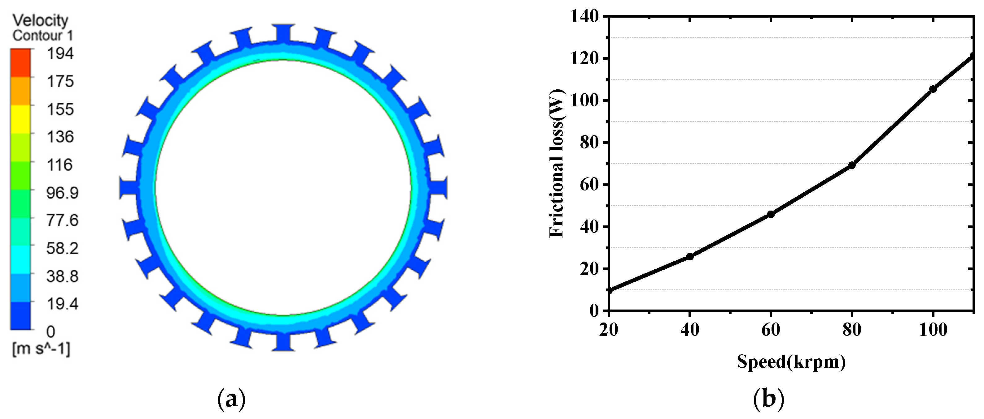
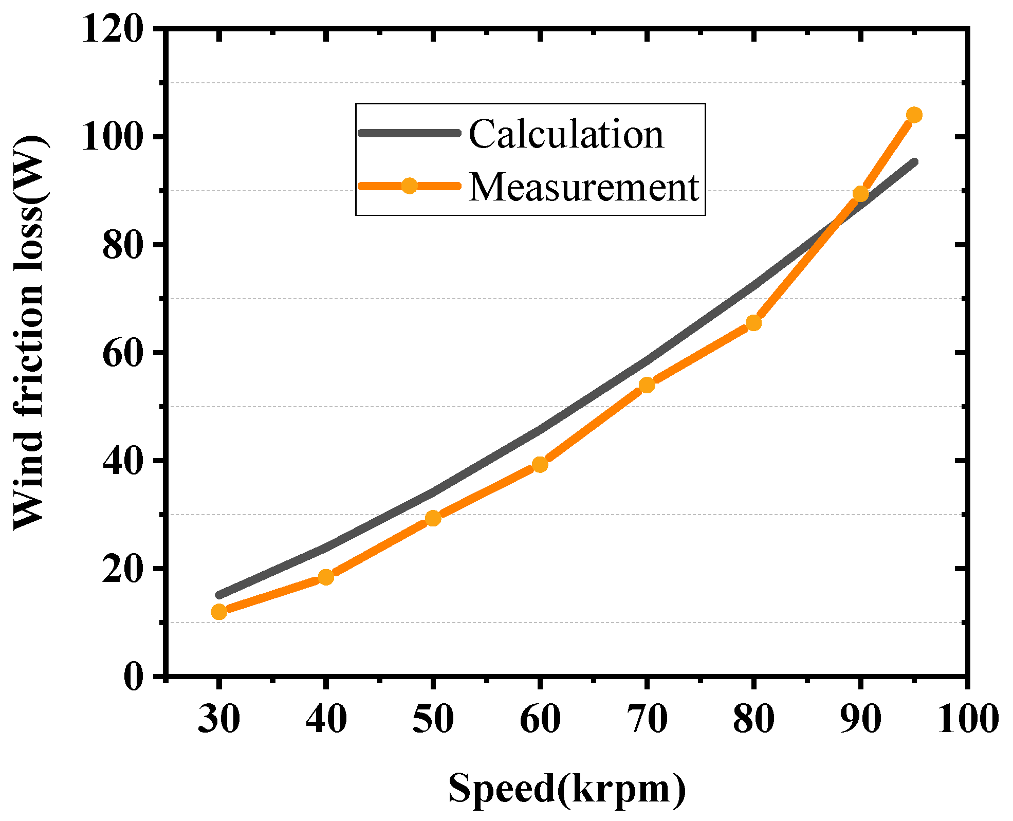
However, the above equation does not take into account the effect of stator slot opening and rotor ventilation on the calculation of wind friction loss of the motor, so in order to calculate the wind friction loss of the UHSPMM more accurately, a computational fluid dynamics (CFD) model was established. Through CFD simulation, the wind friction loss of UHSPMM is 95.3 W. Figure 3a shows the air flow field distribution located between the stator slot and the rotor outer circle, where the maximum value is 194 m/s, and Figure 3b shows the variation curve of wind friction loss with increasing speed, and its value also increases gradually.

3.4. Rotor Eddy Current Loss

As a result of stator slotting, the air gap flux density can be decomposed into a series of non-sinusoidal waveforms with high harmonics. These high harmonics generate a significant amount of eddy current losses in the rotor sleeve. The slot harmonic losses in the rotor sleeve can be calculated using the following equation [34,35]:
P s l = π 3 2 σ s 1 k r B m s l n 2 D s l 3 l s l d s l
where σ s l is the conductivity (s/m); k r is the casing resistance coefficient; B m s l is the amplitude of the high-frequency flux density caused by the slot opening; n is the rotor speed (r/s); D s l is the intermediate diameter (m); l s l is the effective length (m); and d s l is the thickness (m).
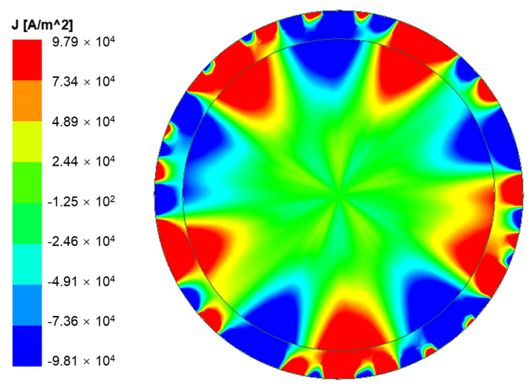
Since the above equation only considered the eddy current loss caused by slot harmonics (space harmonics), and did not take into account the eddy current loss caused by motor input harmonics (time harmonics), a 2D finite element analysis model was established to calculate the eddy current loss of the permanent magnet and the sleeve, respectively, and the eddy current loss distributions of the rotor of the UHSPMM at the rated speed and rated load are shown in Figure 4. Most of the rotor eddy current losses are concentrated on the rotor surface, due to the slotting effect of the non-sinusoidal flux density distribution in the air gap. The average loss values of the rotor sleeve and permanent magnet under the rated conditions are 154.19 W and 23.8 W.
A 3D finite element analysis model was established to further ensure the accuracy of the rotor eddy current loss calculation, and the distributions of the rotor eddy current loss under no load and load status were calculated, respectively, and compared with the 2D results, which can be derived from Table 2, and the errors are all within 5%.

3.5. UHSPMM Temperature Calculation

UHSPMMs have a great disadvantage in thermal management calculations due to their small size, so they need to accurately calculate the temperature distribution inside the motor, especially to accurately predict the operating state of the rotor [36], which is helpful to ensure the reliable operation of the motor for a long time. For UHSPMM, thermal calculations depend on the heat generation of the components and the cooling conditions of the motor [37]; in this study, the stator is cooled by using a seat with a helical water channel and the rotor is cooled by using cooling air supplied separately from outside. The coolant flow rate can be calculated by:
Q w a = P S l o s s ρ w a C p w a T o u t l e t T i n l e t
where P S l o s s is the stator core losses and winding losses in the core (W), ρ w a is the water density (kg/m3), C p w a is the water specific heat capacity (J/(kg·°C)). T o u t l e t and T i n l e t are outlet and inlet water temperature, respectively (°C).
As well, cooling air flow can be calculated by:
Q a i r = P R l o s s ρ a i r C p a i r T o u t T i n
where P R l o s s is the rotor losses, frictional loss, and winding end losses (W), ρ a i r is the air density (kg/m3), C p a i r is the air specific heat capacity (J/(kg·°C)). T o u t and T i n are outlet and inlet air temperature, respectively (°C).
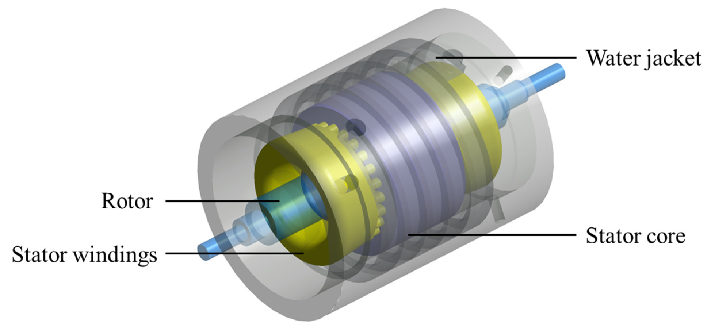
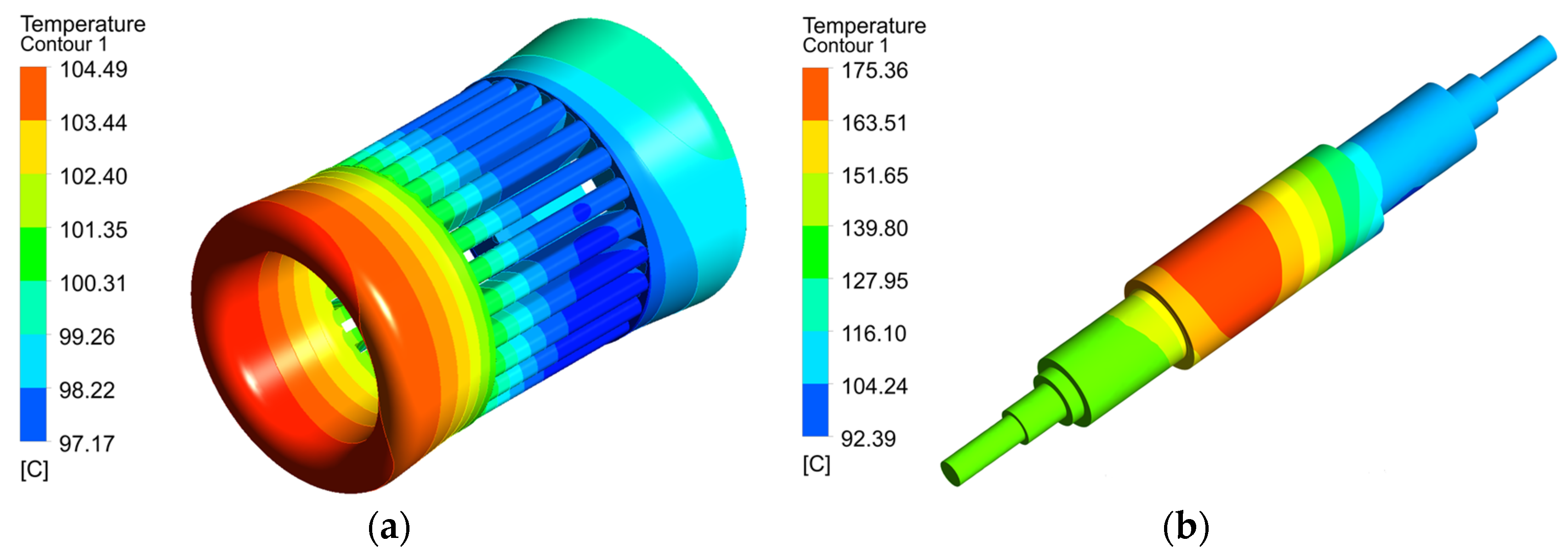
The thermal analysis of the UHSPMM was carried out by CFD; the motor components were set as heat sources in the form of power loss densities; in order to take into account the effect on cooling during high-speed rotation, the outer surface of the rotor in contact with the air gap was set as a moving wall; the standard K-ε model is set in the air region for turbulence; the viscous dissipation term is included in the software. Figure 5 shows the 3D model of the thermal calculation with a spiral cooling water channel in the motor housing. The power loss of UHSPMM reaches the maximum value at 95 k/min and 25 kW; therefore, the thermal validation is carried out under this operating condition, and the loss distribution is shown in Table 3. The flow rate of cooling water is set to 12 L/min and the initial temperature is 30 °C. The cooling air flow rate was set to 14 g/s and the temperature was 40 °C. The pressure and temperature distributions of the water jacket were obtained by CFD calculations, as shown in Figure 6. The temperature of the winding and rotor is depicted in Figure 7. Due to the highest temperature of 104 °C of the enclosed housing located at the end of the windings, and 175.4 °C at the protection sleeve and permanent magnet of the rotor, the permanent magnet adopts Sm2Co17 for its low-temperature coefficient, having an operating temperature of up to 250 °C, and as such, it can be operated safely for long periods of time.

4. UHSPMM Rotor Strength Analysis

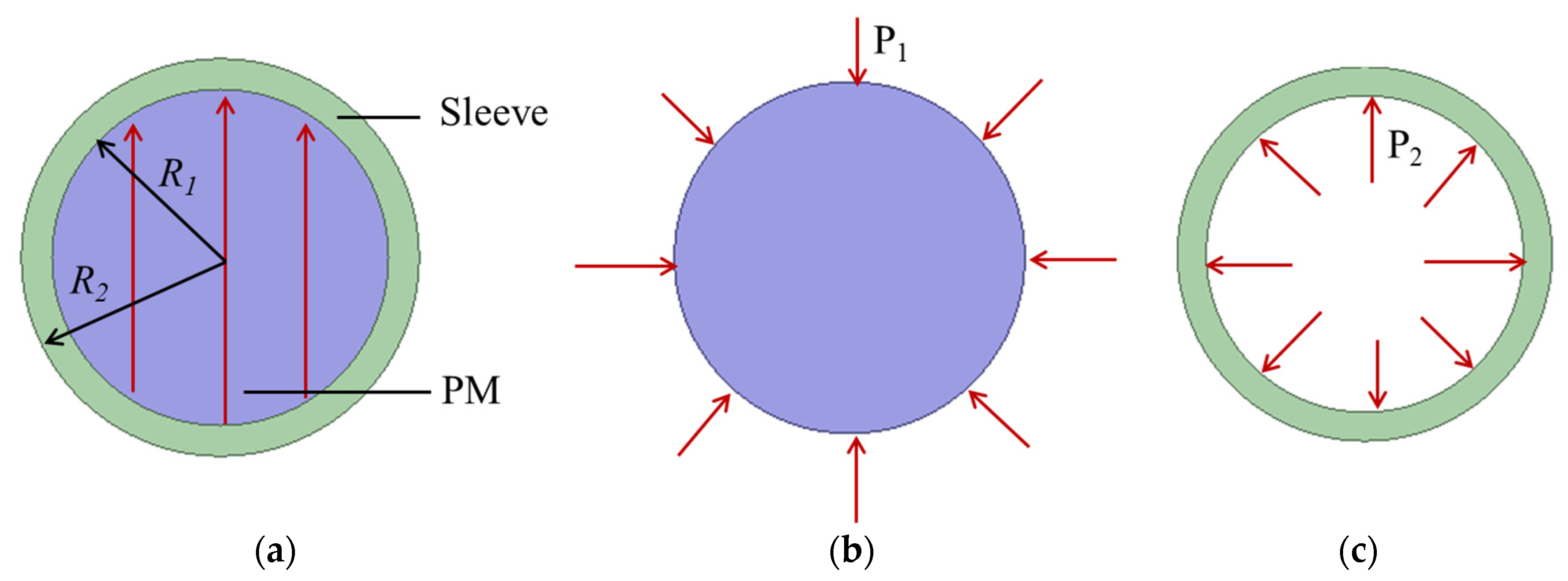
The increase in centrifugal force at the limiting speed and the increase in rotor temperature will lead to a change in pressure between the sleeve and the permanent magnet, and the function of the protective sleeve is to keep a certain positive pressure on the permanent magnet all the time. Figure 8 shows the rotor section of the UHSPMM, and the centrifugal force σ t of the sleeve and σ m of the permanent magnet are calculated as follows [38]:
σ t = ρ s ω 2 8 2 1 v R 1 2 + 6 4 v 1 v R 2 2
σ m = ρ m ω 2 3 R 2 R 1 R 1 3
where ρ s is the density of the protection sleeve, ρ m is the density of the permanent magnet, v is Poisson’s ratio, ω is the rotation angular speed, R 1 and R 2 are the outer diameters of the permanent magnet and the sleeve, P 1 and P 2 are the assembly pressure generated by the interference fit between the sleeve and the permanent magnet.
The stresses σ and strains ε in the sleeve due to centrifugal force are:
σ = σ t + σ m
ε = σ / E
where E is the Young’s modulus of the sleeve.
The stress σ s m a x due to the change in temperature when the sleeve is at the limiting speed is:
σ s m a x = E ε i + σ = E ε + α Δ T + σ
where ε i is the interference between the sleeve and the permanent magnet and Δ T is the temperature rise of the sleeve; α is the linear thermal expansion coefficient.

4.1. Rotor Stress with Extreme Speed and Extreme Temperature

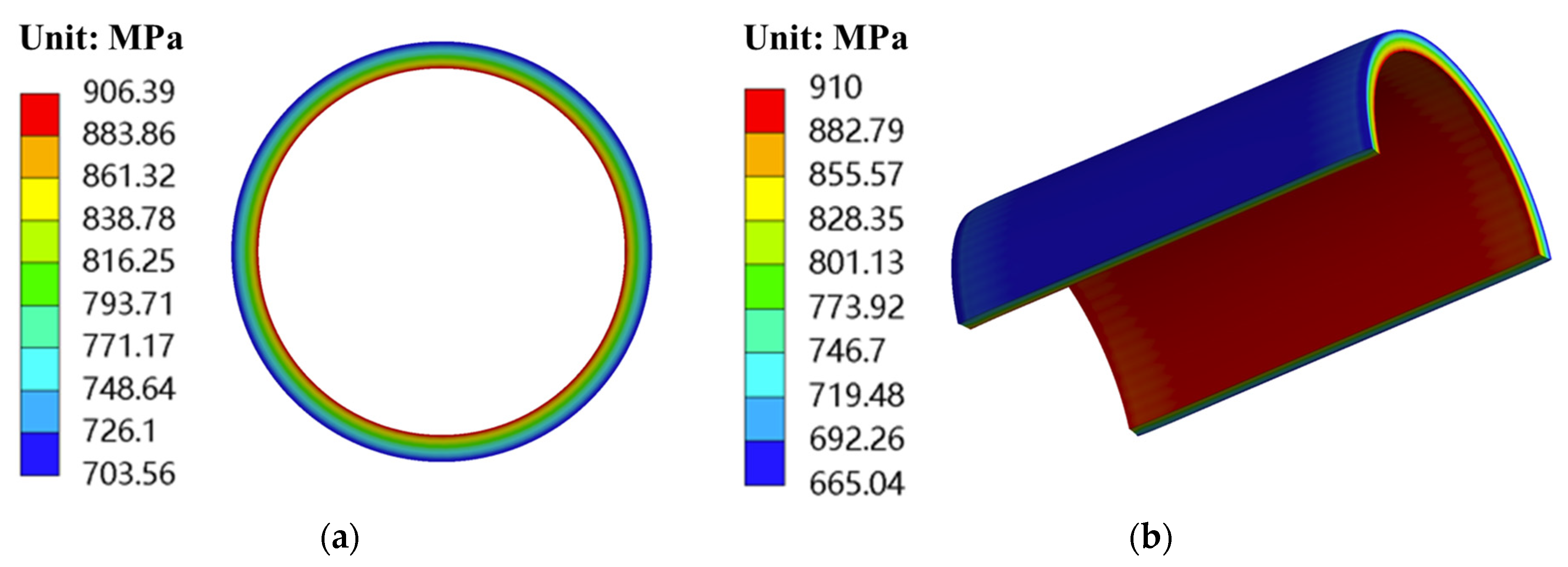
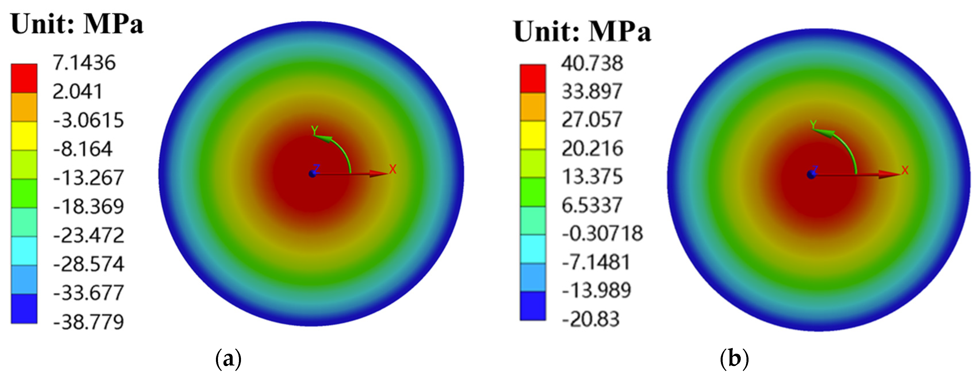
The 2D and 3D finite element analysis models with different temperatures and speeds were further developed, in order to more accurately compare the mechanical characteristics of the rotor of the UHSPMM under different operating conditions, as shown in Figure 9. Three different working conditions were specifically studied: (A) rotor in rated speed rotation at normal temperature (95 krpm@22 °C); (B) rotor in rated speed rotation at high temperature (95 krpm@180 °C); (C) rotor in extreme speed rotation at high temperature (110 krpm@180 °C). The material properties of the high-temperature alloy protective cover and permanent magnets used in the UHSPMM are shown in Table 4. Table 5 shows the sleeve and PM maximum stresses for the UHSPMM rotor at the three conditions by FEM.
Negative values in the table indicate that they are subjected to compressive stresses. For permanent magnets, they can withstand large compressive stresses and small tensile stresses, so they need to be focused on during design. As can be seen from Table 4, when the temperature at the rated speed at room temperature under the working condition point A rises to the rated speed limit temperature at condition point B, due to the different coefficients of thermal expansion of the sleeve and the permanent magnet, the sleeve stress decreases significantly, and the tangential stress of the permanent magnet is changed from a certain amount of compressive stress to tensile stress; with the further increase in rotational speed, at the working condition point C, due to the difference in the centrifugal force between the permanent magnet and alloy sleeve at the high rotational speed, on the contrary, the sleeve stress rises, but the tangential stress of the permanent magnet further deteriorates and approaches the limit value. Therefore, for the UHSPMM rotor design, the influence of the operating temperature on the mechanical properties must be taken into account.
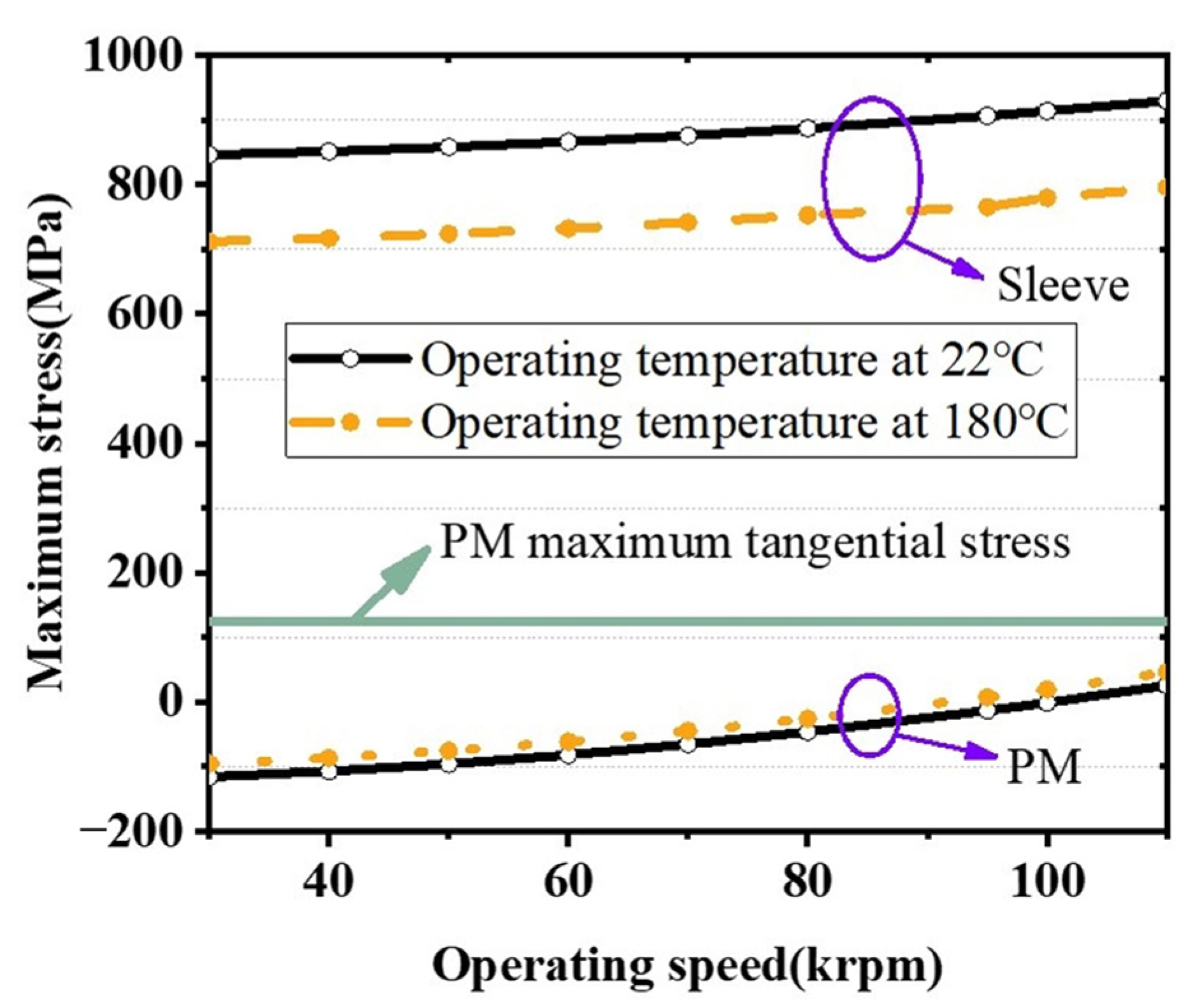
Figure 10 shows the variation curves of the maximum stresses of the permanent magnet and the sleeve, respectively, at different temperatures as the rotational speed increases, and it can be clearly seen that the maximum stresses of both the permanent magnet and the sleeve increase sharply at the limiting temperature. Figure 11, Figure 12 and Figure 13 show the equivalent stress distributions of the sleeve and the tangential stress distributions of the PM for the UHSPMM rotor at the rated speed and extreme speed at extreme temperature, respectively.
The effect of sleeve thickness and overload on rotor strength performances at extreme speeds and temperatures was further investigated, as shown in Figure 14. It can be seen that both too large an excess and too small a sleeve thickness will increase the compressive stress in the sleeve. As the thickness of the sleeve increases, the tangential stress of the permanent magnet gradually decreases, but the eddy current loss of the sleeve also increases; in order to balance the eddy current loss of the sleeve and the tangential stress of the permanent magnet, the sleeve is finally selected to be 3 mm, as shown in Figure 12b, and the tangential stress of the permanent magnet is close to the limit at the extreme rotational speed. Compared with the thickness of the sleeve, the size of the interference has a more obvious effect on the stress distribution of the sleeve. The tangential stress of the permanent magnet does not change much when the excess is constant. As the sleeve thickness of the UHSPMM rotor is 3 mm, the effects of interference on rotor mechanical performances are quantified in Figure 15. For the interference varying from 0.02 mm to 0.10 mm, the sleeve maximum radial stress changes from −281.04 MPa to −1218.3 MPa; for the PM maximum tangential stress, it ranges from −81.825 MPa to −60.45 MPa.
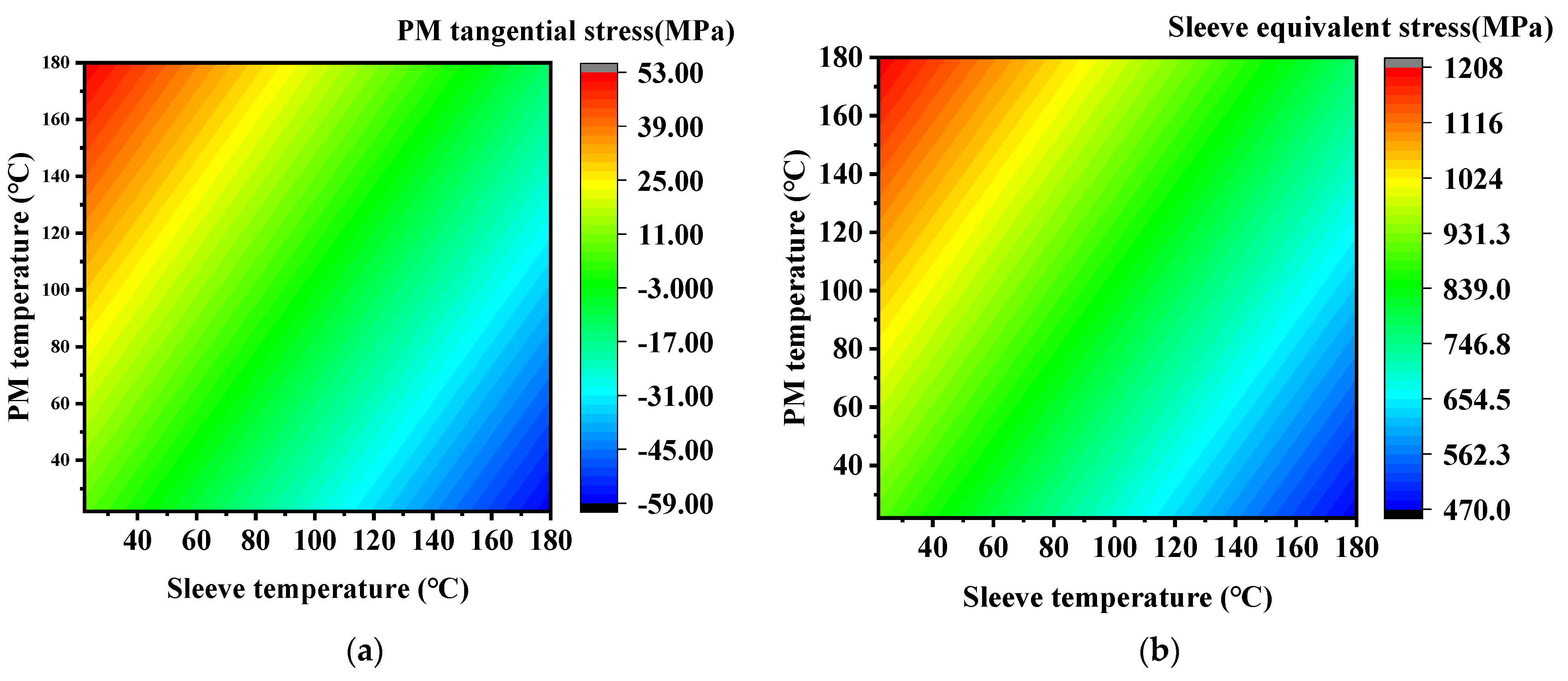
Similarly, when the permanent magnet and the alloy sleeve are at different temperatures, the stress suffered under high-speed operation of the rotor also changes accordingly. It can be seen from Figure 16 that when the alloy sleeve is at a lower temperature, the tensile stress of the permanent magnet rises correspondingly with the increase in the temperature of the permanent magnet, and accordingly, the stress of the alloy sleeve increases.
In order to avoid exceeding the working limit of permanent magnet and sleeve stress, as well as to reduce the wind friction when the rotor is running at ultra-high speed, the air volume for cooling the rotor cannot be too large; at the same time, in order to ensure that the rotor is running at a lower temperature, the cooling air volume cannot be too small either. Therefore, based on the size of the air gap and the limitations of the cooling conditions, it is necessary to accurately calculate the rotor cooling air volume.

4.2. Rotor Dynamic Analysis with Extreme Temperature

The rated speed n r a should be under the bending critical speed n c r of the rigid rotor, to avoid rotor resonance at high speeds, normally n r a < 0.75 n c r [39,40]. The FEM of the rotor of the UHSPMM is shown in Figure 17; the air bearing stiffness is set as 3 × 10 5 N/m.
The equation of critical speed of the rotor is [41,42]:
k x z ω i 2 M x z y i = 0
where k x z is the stiffness coefficient matrix of the rotor, M x z is the mass matrix of the rotor, ω i is the rotor angular velocity, y i is the critical speed of the rotor.
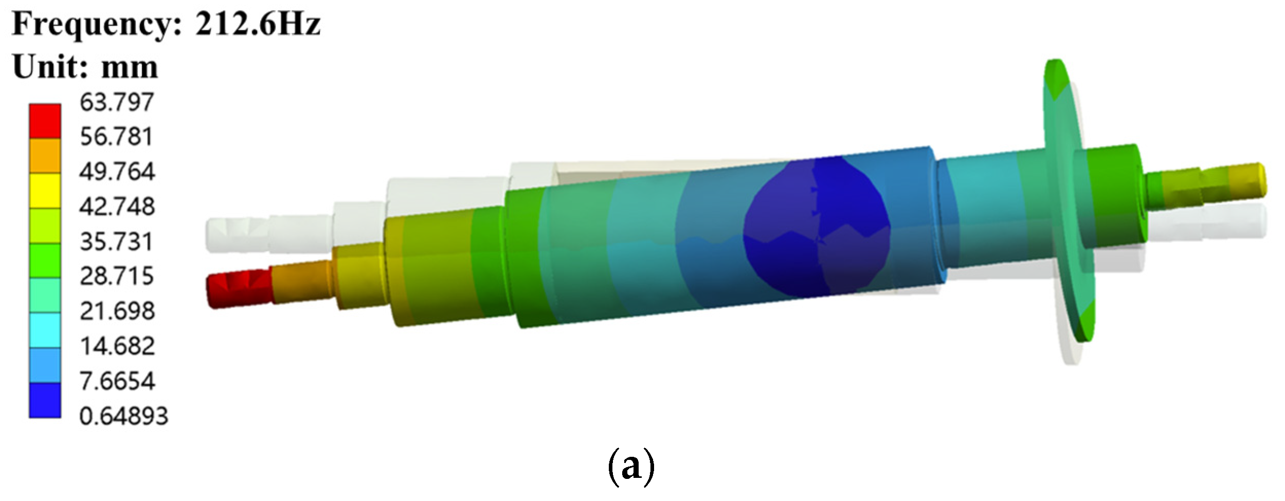
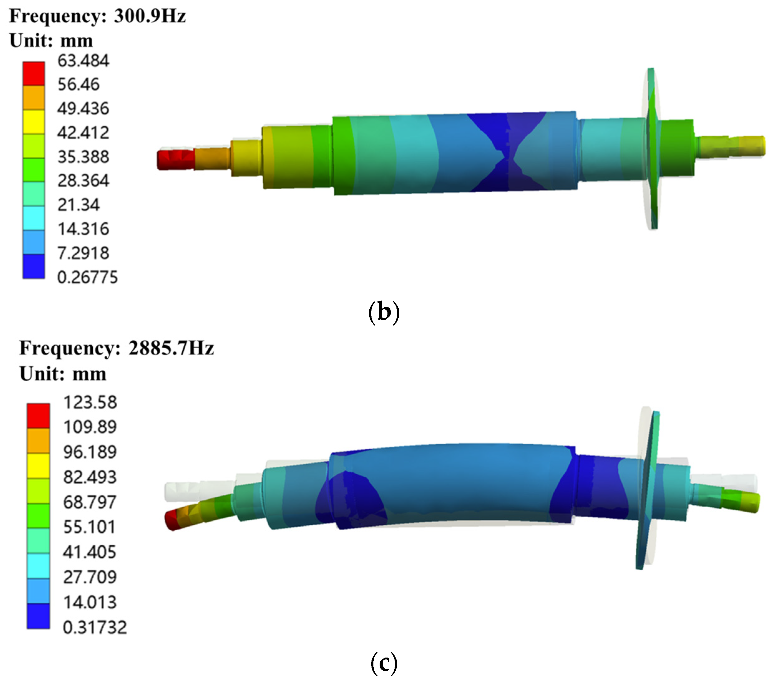
The vibration mode corresponding to the first-order critical speed is conical rigid mode at 12,753 rpm, the second-order critical speed is swing mode at 18,054 rpm, and the third-order critical speed is first-order bending mode at 173,140 rpm, which is more suitable for ultra-high-speed design requirements, as shown in Figure 18 and Figure 19.

5. Prototype Design and Experimental Analysis

A prototype was fabricated by the above design and Figure 20a,b show the rotor and stator, respectively. As one of the most important performance parameters for detecting the no-load reverse potential of the permanent magnet motor, because the motor rotates at high speed and cannot be measured by pair towing or prime mover towing, it is used to revoke the frequency converter control. The power is suddenly cut off when running at high speed, so as to achieve the purpose of measuring the no-load reverse potential through the measurement of the motor winding end voltage by the power analyzer.
The motor running speed decreased to 60 krpm when disconnected from the inverter control, in order to reduce the damage caused by the air bearing in the high-speed stage of the sudden stall, as shown in Figure 21. The calculation and measurement of the error is gradually smaller with the increase in speed; the maximum error occurs at 30 krpm, which is close to 4%. The reason is that the rotor working temperature is low at low speed, which is different from the design working temperature.
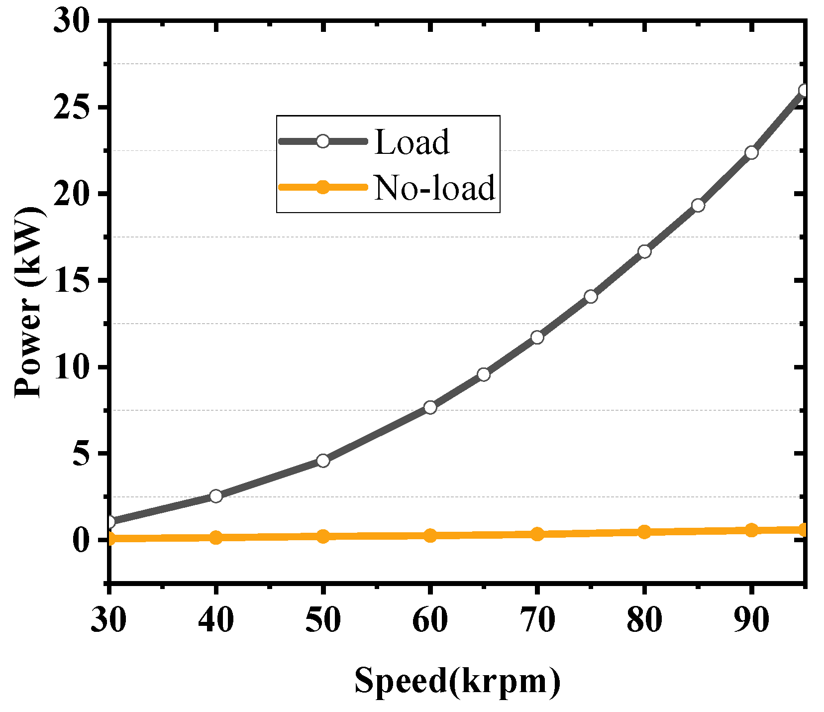
No-load and load tests were carried out on the UHSPMM over the full speed range to further verify the performance of the motor, and the power of the motor increased rapidly with increasing speed, as shown in Figure 22.
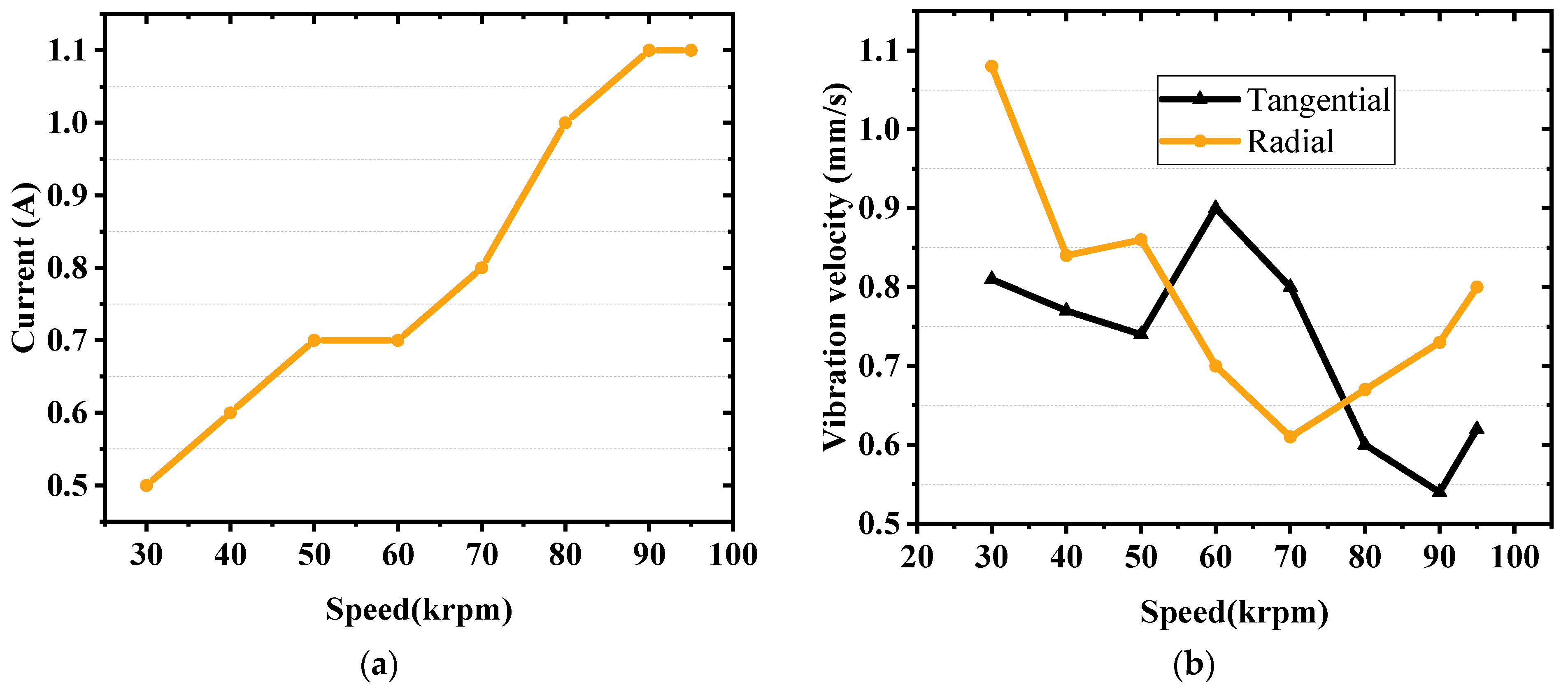
An overspeed test is conducted in order to further verify the stability of the rotor at extreme rotational speeds, as well as the reasonableness of the rotor dynamics. The motor is driven by the inverter to run to 95 krpm under no load, and the values of the casing vibration and the current input to the stator are detected, as shown in Figure 23.
The stator current is smoothly increased with the motor speed, and the radial vibration and tangential vibration of the casing are smooth with a maximum value not exceeding 1.1 mm/s. After disassembling the motor and carefully observing, no abnormalities were found, which proved the stability of the rotor structure.
Wing friction losses cannot be measured directly during the test, which can be separated from the total no-load loss. The relationship between the air friction loss and rotating speed can be expressed as [43]
P a i r = α n β
where n is rotating speed, and α and β are the calculated coefficients. Through the nonlinear fitting to the data in Figure 3, the coefficients α and β can be obtained as 2.6 and 1.6, respectively. The input power during the no-load test obtained by the power analyzer is shown in Figure 22.
The total losses of UHSPMM under no-load can be written as
P n o l o a d = P F e + P a i r + P w i n d i n g + P A d
where P F e is the stator iron loss, P w i n d i n g is the winding loss, and P A d is the other additional losses that cannot be accurately calculated. Comparing the calculation of the air friction loss with the measurement from loss separation, the change curve is shown in Figure 24.
It can be seen that the measured value is smaller than the calculated value when the rotational speed does not exceed 90 krpm, but the general trend is consistent. It is difficult to calculate the wind abrasion consistently with the measured value because the gas film dynamic characteristics cannot be measured, and it is also affected by the rotor structure, surface roughness, and rotor ventilation, which leads to the measured value being larger than the calculated value after exceeding the rated speed.
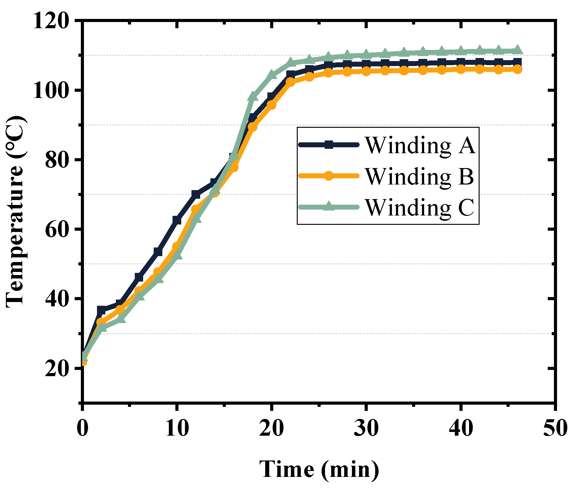
Pt100 resistance thermometers were tied to the ends of the three-phase windings, respectively, in order to detect the stator winding temperature in real time and to prevent the operating temperature from exceeding the limits permitted by the insulation class. With the load test, the detected stator winding temperature is shown in Figure 25 and Table 6, the maximum temperature reaches 111.3 °C, and the average maximum temperature of the winding is 108.3 °C, which is not more than 4% compared with the theoretically calculated maximum temperature of 104.5 °C. In addition, the whole high-speed motor is in a closed state, and it is not possible to practically monitor the rotor operating temperature, which can only be predicted by detecting the change of input current at constant load.
When the rated working condition is reached, the load current is 40.9 A; after running for 10 min, the current rises slightly to 41.6 A and then remains constant, with a deviation of 1.2 A from the design value of the initial scheme. The permanent magnets are unable to provide sufficient magnetic chain at higher temperatures, and a constant load can only be achieved by increasing the stator current. By calculating the rotor operating temperature as slightly lower than the present value, the actual operating temperature of the rotor should be 169.2 °C, which is 3.7% different from the value obtained during the temperature field analysis, and is in line with the design objective.

6. Conclusions

In this paper, a 25 kW, 95,000 rpm UHSPMM is researched, with its rotor mechanical stress and dynamics, power losses, and thermal performance studied. The accuracy of the design was well verified by prototyping and testing. In the field of ultra-high-speed motor design, the strength calibration of each rotor component is very critical, especially the dynamic analysis of the whole rotor, which can effectively avoid the vibration of the unit caused by approaching or being at the critical speed; because the high-speed motor works in the range of ultra-high speed, the volume can be very small under the same power, but it puts forward higher requirements for the thermal management, which is affected by the high harmonics, and generates the eddy current loss in the rotor sleeve and the permanent magnet. The high harmonic influence, in the rotor sleeve and permanent magnets, produces non-negligible eddy current losses, which further aggravate the temperature rise of the rotor, and must take into account the output performance of the motor at the limit temperature and the structural stability of the rotor components at high temperatures. Through the prototype test, the output power of the motor is far from the limit of the design, so it is necessary to carry out further research on reducing the usage of permanent magnets.

Author Contributions

Conceptualization, M.C., Z.L. and S.X.; methodology, M.C.; software, Z.L.; validation, M.C., Z.L. and S.X.; formal analysis, Z.L.; investigation, S.X.; resources, R.P.; data curation, M.C.; writing—original draft preparation, M.C.; writing—review and editing, Z.L. and S.X.; visualization, S.X.; supervision, M.C.; project administration, S.X.; funding acquisition, R.P. All authors have read and agreed to the published version of the manuscript.

Funding

This research was supported by program of Shenyang University of Technology Interdisciplinary Team Project (No. 100600453) and Central guide to local science and technology development funds (free exploration class basic research) (No. 2023JH6/100100043).

Data Availability Statement

The data are not publicly available for privacy reasons. The data presented in this study are available from the corresponding author.

Conflicts of Interest

The authors declare no conflicts of interest.

References

  1. Kim, J.-H.; Kim, D.-M.; Jung, Y.-H.; Lim, M.-S. Design of Ultra-High-Speed Motor for FCEV Air Compressor Considering Mechanical Properties of Rotor Materials. IEEE Trans. Energy Convers. 2021, 36, 2850–2860. [Google Scholar] [CrossRef]
  2. Zhao, F.; Yu, Z.; Cao, J.; Li, L. Design and Optimization of a High-Speed Permanent Magnet Synchronous Machine for Gas Compressors. IEEE Trans. Magn. 2022, 58, 8100905. [Google Scholar] [CrossRef]
  3. Zhang, H.; Yu, W.; Hua, W. Design and Key Technology of Oil-Free Centrifugal Air Compressor for Hydrogen Fuel Cell. Trans. Electr. Mach. Syst. 2022, 6, 11–19. [Google Scholar] [CrossRef]
  4. Lim, M.-S.; Kim, J.-M.; Hwang, Y.-S.; Hong, J.-P. Design of an Ultra-High-Speed Permanent-Magnet Motor for an Electric Turbocharger Considering Speed Response Characteristics. IEEE/ASME Trans. Mechatron. 2017, 22, 774–784. [Google Scholar] [CrossRef]
  5. Hong, D.-K.; Woo, B.-C.; Lee, J.-Y.; Koo, D.-H. Ultra High Speed Motor Supported by Air Foil Bearings for Air Blower Cooling Fuel Cells. IEEE Trans. Magn. 2012, 48, 871–874. [Google Scholar] [CrossRef]
  6. Gerada, D.; Mebarki, A.; Brown, N.L.; Gerada, C.; Cavagnino, A.; Boglietti, A. High-Speed Electrical Machines: Technologies, Trends, and Developments. IEEE Trans. Ind. Electron. 2014, 61, 2946–2959. [Google Scholar] [CrossRef]
  7. Tenconi, A.; Vaschetto, S.; Vigliani, A. Electrical Machines for High-Speed Applications: Design Considerations and Tradeoffs. IEEE Trans. Ind. Electron. 2014, 61, 3022–3029. [Google Scholar] [CrossRef]
  8. Hong, D.-K.; Woo, B.-C.; Jeong, Y.-H.; Koo, D.-H.; Ahn, C.-W. Development of an ultra high speed permanent magnet synchronous motor. Int. J. Precis. Eng. Manuf. 2013, 14, 493–499. [Google Scholar] [CrossRef]
  9. Shen, J.; Qin, X.; Wang, Y. High-speed permanent magnet electrical machines—Applications, key issues and challenges. Trans. Electr. Mach. Syst. 2018, 2, 23–33. [Google Scholar] [CrossRef]
  10. Li, S.; Li, Y.; Choi, W.; Sarlioglu, B. High-Speed Electric Machines: Challenges and Design Considerations. IEEE Trans. Transp. Electrif. 2016, 2, 2–13. [Google Scholar] [CrossRef]
  11. Zhang, Y.; Wang, H.; Gerada, C. Rotor Eddy Current Loss and Multiphysics Fields Analysis for a High-Speed Permanent Magnet Machine. IEEE Trans. Ind. Electron. 2021, 68, 5100–5111. [Google Scholar] [CrossRef]
  12. Zhu, Z.; Huang, Y.; Dong, J.; Peng, F.; Yao, Y. Rotor Eddy Current Loss Reduction with Permeable Retaining Sleeve for Permanent Magnet Synchronous Machine. IEEE Trans. Energy Convers. 2020, 35, 1088–1097. [Google Scholar] [CrossRef]
  13. Kolondzovski, Z.; Arkkio, A.; Larjola, J.; Sallinen, P. Power Limits of High-Speed Permanent-Magnet Electrical Machines for Compressor Applications. IEEE Trans. Energy Convers. 2011, 26, 73–82. [Google Scholar] [CrossRef]
  14. Du, G.; Huang, N.; He, H.; Lei, G.; Zhu, J. Parameter Design for a High-Speed Permanent Magnet Machine under Multiphysics Constraints. IEEE Trans. Energy Convers. 2020, 35, 2025–2035. [Google Scholar] [CrossRef]
  15. Ismagilov, F.R.; Uzhegov, N.; Vavilov, V.E.; Bekuzin, V.I.; Ayguzina, V.V. Multidisciplinary Design of Ultra-High-Speed Electrical Machines. IEEE Trans. Energy Convers. 2018, 33, 1203–1212. [Google Scholar] [CrossRef]
  16. Ma, J.; Zhu, Z.Q. Optimal split ratio in small high speed PM machines considering both stator and rotor loss limitations. Trans. Electr. Mach. Syst. 2019, 3, 3–11. [Google Scholar] [CrossRef]
  17. Binder, A.; Schneider, T.; Klohr, M. Fixation of buried and surface-mounted magnets in high-speed permanent-magnet synchronous machines. IEEE Trans. Ind. Appl. 2006, 42, 1031–1037. [Google Scholar] [CrossRef]
  18. Li, W.; Qiu, H.; Zhang, X.; Cao, J.; Zhang, S.; Yi, R. Influence of Rotor-Sleeve Electromagnetic Characteristics on High-Speed Permanent-Magnet Generator. IEEE Trans. Ind. Electron. 2014, 61, 3030–3037. [Google Scholar] [CrossRef]
  19. Shen, Q.; Zhou, Z.; Li, S.; Liao, X.; Wang, T.; He, X.; Zhang, J. Design and Analysis of the High-Speed Permanent Magnet Motors: A Review on the State of the Art. Machines 2022, 10, 549. [Google Scholar] [CrossRef]
  20. Yu, Y.; Liang, D.; Liu, X. Optimal Design of the Rotor Structure of a HSPMSM Based on Analytic Calculation of Eddy Current Losses. Energies 2017, 10, 551. [Google Scholar] [CrossRef]
  21. Jung, D.-H.; Lee, J.-K.; Kim, J.-Y.; Jang, I.S.; Lee, J.; Lee, H.-J. Design method of an ultra-high speed PM Motor/Generator for Electric-Turbo Compounding System. IEEE Trans. Appl. Supercond. 2018, 28, 5202804. [Google Scholar] [CrossRef]
  22. Li, L.; Li, W.; Li, D.; Zhang, X.; Fan, Y. Influence of sleeve thickness and various structures on eddy current losses of rotor parts and temperature field in surface mounted permanent-magnet synchronous motor. IET Electr. Power Appl. 2018, 12, 1183–1191. [Google Scholar] [CrossRef]
  23. Lee, T.-W.; Hong, D.-K. Rotor Design, Analysis and Experimental Validation of a High-Speed Permanent Magnet Synchronous Motor for Electric Turbocharger. IEEE Access 2022, 10, 21955–21969. [Google Scholar] [CrossRef]
  24. Barrans, S.; Mallin, L. Mechanical Design of Rotors with Surface Mounted Permanent Magnets. In Electric Machines for Smart Grids Applications—Design, Simulation and Control; El-Shahat, A., Ed.; IntechOpen: London, UK, 2018. [Google Scholar]
  25. Binder, A.; Schneider, T. High-speed inverter-fed AC drives. In Proceedings of the 2007 International Aegean Conference on Electrical Machines and Power Electronics, Bodrum, Turkey, 10–12 September 2007; IEEE: New York, NY, USA, 2007; pp. 9–16. [Google Scholar]
  26. Ahn, J.; Han, C.; Kim, C.; Choi, J. Rotor Design of High-Speed Permanent Magnet Synchronous Motors Considering Rotor Magnet and Sleeve Materials. IEEE Trans. Appl. Supercond. 2018, 28, 5201504. [Google Scholar] [CrossRef]
  27. Ionel, D.M.; Popescu, M.; McGilp, M.I.; Miller, T.J.E.; Dellinger, S.J.; Heideman, R.J. Computation of Core Losses in Electrical Machines Using Improved Models for Laminated Steel. IEEE Trans. Ind. Appl. 2007, 43, 1554–1564. [Google Scholar] [CrossRef]
  28. Zhu, Z.-Q.; Xue, S.; Chu, W.; Feng, J.; Guo, S.; Chen, Z.; Peng, J. Evaluation of Iron Loss Models in Electrical Machines. IEEE Trans. Ind. Appl. 2019, 55, 1461–1472. [Google Scholar] [CrossRef]
  29. Iwasaki, S.; Deodhar, R.P.; Liu, Y.; Pride, A.; Zhu, Z.Q.; Bremner, J.J. Influence of PWM on the Proximity Loss in Permanent-Magnet Brushless AC Machines. IEEE Trans. Ind. Appl. 2009, 45, 1359–1367. [Google Scholar] [CrossRef]
  30. Vandelac, J.-P.; Ziogas, P.D. A novel approach for minimizing high-frequency transformer copper losses. IEEE Trans. Power Electron. 1988, 3, 266–277. [Google Scholar] [CrossRef]
  31. Polkowski, J.W. Turbulent Flow Between Coaxial Cylinders with the Inner Cylinder Rotating. J. Eng. Gas Turbines Power 1984, 106, 128–135. [Google Scholar] [CrossRef]
  32. Awad, M.N.; Martin, W.J. Windage loss reduction study for TFTR pulse generator. In Proceedings of the 17th IEEE/NPSS Symposium Fusion Engineering (Cat. No.97CH36131), San Diego, CA, USA, 6–9 October 1997; IEEE: New York, NY, USA, 1998; pp. 1125–1128. [Google Scholar]
  33. Bilgen, E.; Boulos, R. Functional Dependence of Torque Coefficient of Coaxial Cylinders on Gap Width and Reynolds Numbers. J. Fluids Eng. 1973, 95, 122–126. [Google Scholar] [CrossRef]
  34. Zhang, Z.; Deng, Z.; Sun, Q.; Peng, C.; Gu, Y.; Pang, G. Analytical Modeling and Experimental Validation of Rotor Harmonic Eddy-Current Loss in High-Speed Surface-Mounted Permanent Magnet Motors. IEEE Trans. Magn. 2019, 55, 8100811. [Google Scholar] [CrossRef]
  35. Gieras, J.F.; Koenig, A.C.; Vanek, L.D. Calculation of eddy current losses in conductive sleeves of synchronous machines. In Proceedings of the 2008 18th International Conference on Electrical Machines, Vilamoura, Portugal, 6–9 September 2008; IEEE: New York, NY, USA, 2008; pp. 1–4. [Google Scholar]
  36. Dong, B.; Wang, K.; Han, B.; Zheng, S. Thermal Analysis and Experimental Validation of a 30 kW 60,000 r/min High-Speed Permanent Magnet Motor with Magnetic Bearings. IEEE Access 2019, 7, 92184–92192. [Google Scholar] [CrossRef]
  37. Saari, J. Thermal analysis of high speed induction machines. In Acta polytechnica Scandinavica El; Electrical Engineering Series; Finnish Acad. of Technology: Espoo, Finland, 1998. [Google Scholar]
  38. Dong, J.; Huang, Y.; Jin, L.; Guo, B.; Zhou, T.; Lin, H.; Dong, J. Development of an air-cooled 150 kW high speed permanent magnet motor with Gramme ring windings for turbo blowers. In Proceedings of the 2014 17th International Conference on Electrical Machines and Systems (ICEMS), Hangzhou, China, 22–25 October 2014; IEEE: New York, NY, USA, 2014; pp. 3534–3538. [Google Scholar]
  39. Hong, D.-K.; Woo, B.-C.; Koo, D.-H. Rotordynamics of 120,000 r/min 15 kW Ultra High Speed Motor. IEEE Trans. Magn. 2009, 45, 2831–2834. [Google Scholar] [CrossRef]
  40. Hong, D.-K.; Woo, B.-C.; Ahn, C.-W.; Koo, D.-H. Unbalance Analysis of 15 KW, 120 krpm, Ultra High Speed Permanent Magnet Synchronous Motor. In Proceedings of the 2012 Sixth International Conference on Electromagnetic Field Problems and Applications, Dalian, China, 19–21 June 2012; IEEE: New York, NY, USA, 2012; pp. 1–4. [Google Scholar]
  41. Wen, B.; Gu, J.; Xia, S.; Wang, Z. Advanced Rotor Dynamic—Theory, Technology and Application; China Machine Press: Beijing, China, 2000; pp. 45–65. [Google Scholar]
  42. American Petroleum Institute. Tutorial on the Api Standard Paragraphs Covering Rotor Dynamics and Balancing: An Introduction to Lateral Critical and Train Torsional Analysis and Rotor Balancing; American Petroleum Institute: Washington, DC, USA, 2003. [Google Scholar]
  43. Huang, Z.; Fang, J.; Liu, X.; Han, B. Loss Calculation and Thermal Analysis of Rotors supported by Active Magnetic Bearings for High-speed Permanent Magnet Electrical Machines. IEEE Trans. Ind. Electron. 2015, 63, 2027–2035. [Google Scholar] [CrossRef]
Figure 1. Cross-section of UHSPMM.
Energies 17 03072 g001
Figure 2. Loss distribution of iron core.
Energies 17 03072 g002
Figure 3. Calculation of wind friction loss: (a) air flow velocity distribution; (b) wind friction loss under different speeds.
Energies 17 03072 g003
Figure 4. Eddy current density distribution.
Energies 17 03072 g004
Figure 5. Thermal analysis model.
Energies 17 03072 g005
Figure 6. Computational fluid dynamics results at 95 krpm and 25 kW: (a) pressure distribution of water jacket; (b) temperature distribution of water jacket.
Energies 17 03072 g006
Figure 7. Temperature distribution at 95 krpm and 25 kW: (a) winding temperature; (b) rotor temperature.
Energies 17 03072 g007
Figure 8. Rotor structure of the UHSPMM: (a) rotor structure dimensions; (b) force diagram of PM; (c) force diagram of sleeve.
Energies 17 03072 g008
Figure 9. Sleeve stress distributions (T = 22 °C, n = 95 krpm): (a) 2D; (b) 3D.
Energies 17 03072 g009
Figure 10. Variation of rotor stresses with operating speed.
Energies 17 03072 g010
Figure 11. PM tangential stress distributions with different operating speeds (T = 22 °C): (a) n = 95 krpm; (b) n = 110 krpm.
Energies 17 03072 g011
Figure 12. PM tangential stress distributions with different operating speeds (T = 180 °C): (a) n = 95 krpm; (b) n = 110 krpm.
Energies 17 03072 g012
Figure 13. Sleeve equivalent stress distributions with different operating speeds (T = 180 °C): (a) n = 95 krpm; (b) n = 110 krpm.
Energies 17 03072 g013
Figure 14. Maximum sleeve stress and PM maximum tangential stress versus the sleeve thickness: (a) maximum sleeve stress; (b) PM maximum tangential stress.
Energies 17 03072 g014
Figure 15. Sleeve, PM maximum stress variations with interference for 3 mm thickness sleeve: (a) maximum sleeve stress; (b) PM maximum tangential stress.
Energies 17 03072 g015
Figure 16. Sleeve, PM maximum stress variations with temperature: (a) PM tangential stress; (b) sleeve equivalent stress.
Energies 17 03072 g016
Figure 17. UHSPMM rotor with Solid PM.
Energies 17 03072 g017
Figure 18. Campbell diagram of UHSPMM rotor.
Energies 17 03072 g018
Figure 19. Calculated results of mode shape for UHSPMM rotor: (a) 12,753 rpm; (b) 18,054 rpm; (c) 173,140 rpm.
Energies 17 03072 g019aEnergies 17 03072 g019b
Figure 20. UHSPMM prototype: (a) rotor; (b) stator.
Energies 17 03072 g020
Figure 21. Back EMF experimental and calculated results with UHSPMM prototype speed.
Energies 17 03072 g021
Figure 22. Power loss experimental results for UHSPMM prototype.
Energies 17 03072 g022
Figure 23. No-load current and casing vibration under different speed. (a) No-load input current; (b) vibration velocity.
Energies 17 03072 g023
Figure 24. Wind friction loss comparison of calculation and measurement at different speeds.
Energies 17 03072 g024
Figure 25. Measured winding temperatures under load operation.
Energies 17 03072 g025
Table 1. Main design of UHSPMM.
ParametersValueParametersValue
Rated power25 kWRated speed95,000 rpm
Stator outer diameter100 mmExtreme speed 110,000 rpm
Stator slot number24Rotor outer diameter39 mm
Stator inner diameter45 mmPole pair number2
Slot opening width2 mmPole arc pole pitch1
Winding ConnectionYPM materialSm2Co17
Winding layer number2PM thickness16.5 mm
Iron core length56 mmSleeve thickness3 mm
Conductors per slot12PM conductivity110,000 S/m
Phase number3Sleeve conductivity610,000 S/m
Table 2. Rotor eddy current loss.
No LoadRated Load
2D3D2D3D
Sleeve (W)32.8631.23154.19147.69
PM (W)0.510.4923.822.67
Total (W)33.3731.72177.99170.36
Table 3. Loss distribution of UHSPMM.
Stator Iron LossCopper LossWind Frictional LossPM Eddy Current LossSleeve Eddy Current Loss
Loss (W)371.42240.395.323.8154.8
Table 4. Material mechanical properties.
Inconel 718Sm2Co17
Density (kg/m3)81908400
Coefficient of thermal expansion (1/K)13 × 10−69 × 10−6
Young’s Modulus (GPa)211151
Yield strength (MPa)103642 (tensile) 900 (compressive)
Poisson’s ratio0.270.294
Table 5. UHSPMM maximum stress results.
SleevePM
(MPa)Radial (MPa)Tangential (MPa)
A906.39−95.01−13.17
B772.44−74.677.14
C830.24−56.7740.74
Table 6. Temperature results by CFD and measurement.
CFDMeasurement
Winding (°C)104.5108.3
Rotor surface (°C)175.4169.2
Disclaimer/Publisher’s Note: The statements, opinions and data contained in all publications are solely those of the individual author(s) and contributor(s) and not of MDPI and/or the editor(s). MDPI and/or the editor(s) disclaim responsibility for any injury to people or property resulting from any ideas, methods, instructions or products referred to in the content.