1. Introduction
According to the World Business Council for Sustainable Development [
1], there is currently a stock of more than 80 million buildings in Europe built between 1950 and 1975, a period during which energy performance was not considered in building design. Often, these buildings are fit for purpose structurally; however, their energy performance is very poor.
In order to achieve improved energy performance while minimising associated material consumption, a proposed solution is to retain the load-bearing structure but replace the non-load-bearing façade of the building with a modern, energy-efficient building envelope. Improving the energy performance of building envelopes is a critical strategy for achieving the required reduction in space heating and cooling energy demand necessary—by at least 25% from current values—to meet the net zero carbon target for 100% of buildings by 2030 [
2].
One of the most commonly proposed methods of enhancing the energy performance of a building is to use the mass of the building’s envelope to store thermal energy temporarily, that is, as a thermal energy storage (TES) system. This absorption and storage of heat during the day can reduce overheating of the internal environment in a building and hence reduce the energy demand of the air conditioning system. The stored heat is then dissipated into the internal environment at night when the temperature of the building naturally reduces. This use of TES improves the thermal comfort of the occupants by moderating internal temperature fluctuations while also shifting electricity consumption to off-peak periods.
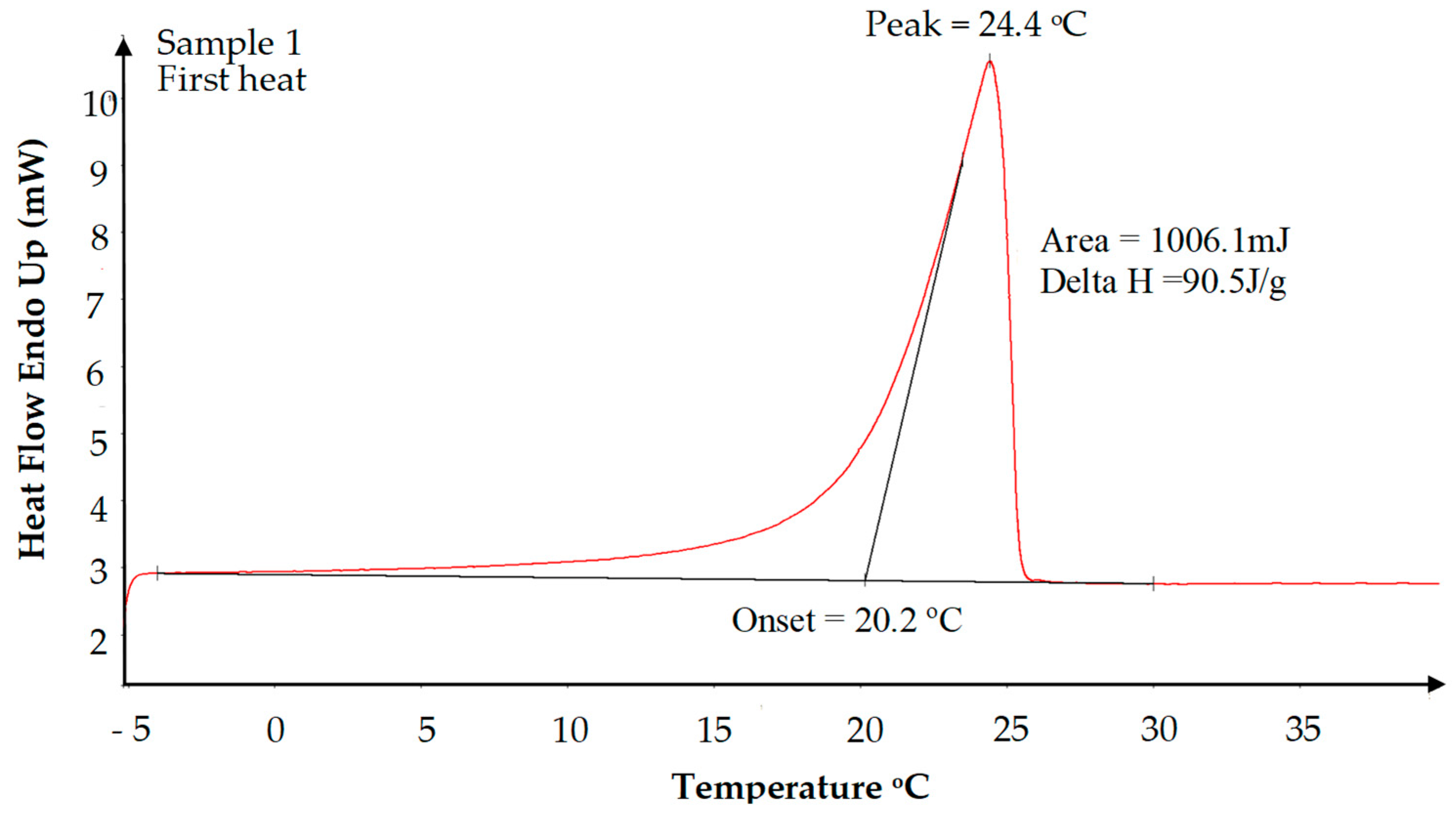
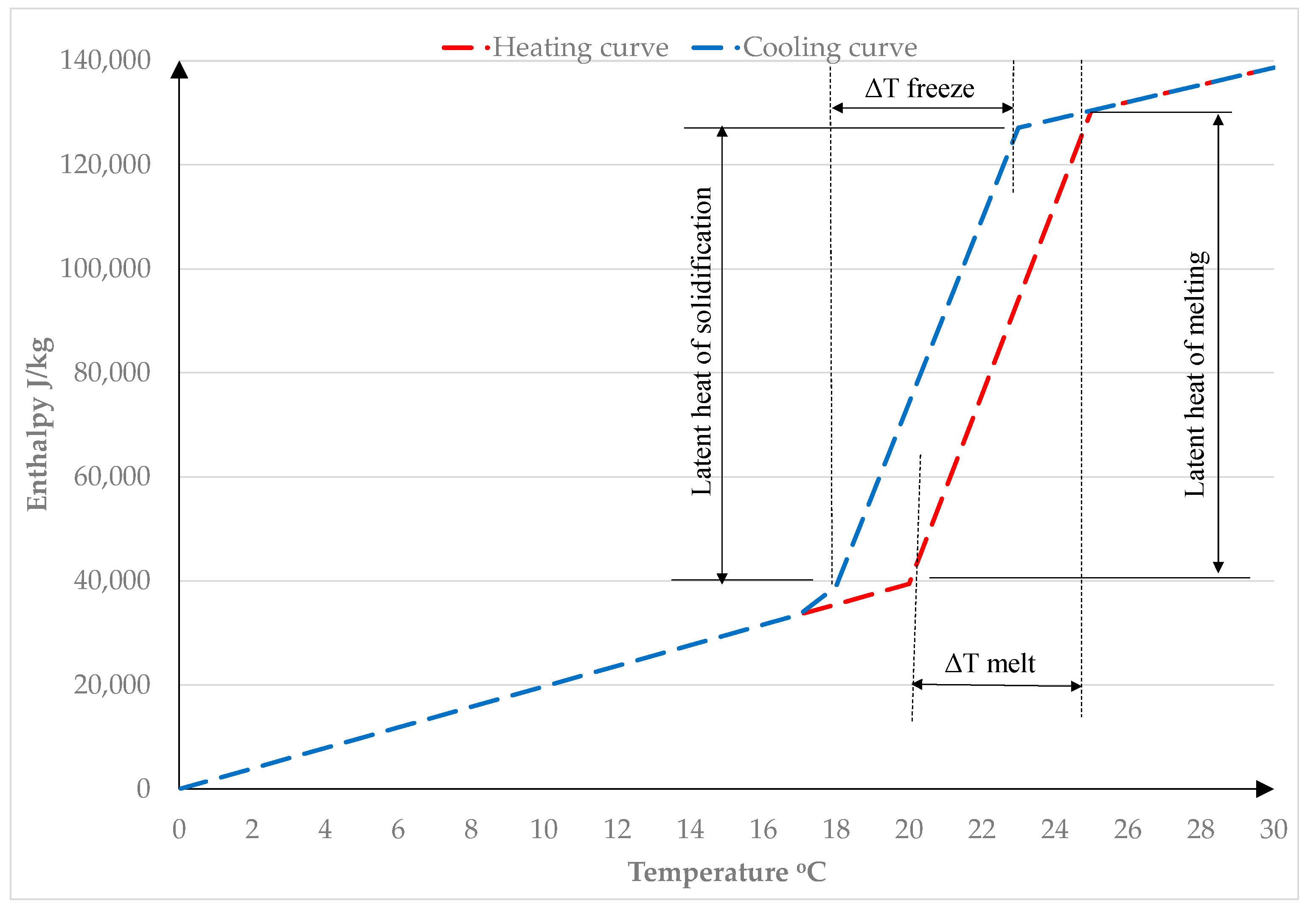
An area of research that is gaining attention is the enhancement of TESs through the addition of phase change materials (PCMs) due to their high energy storage density capabilities and their ability to store thermal energy in a constant temperature phase transition process, that is, PCMs provide an enhanced latent heat capacity (
Figure 1).
There are many studies in the literature which review the use of PCMs in building envelopes [
3,
4,
5,
6,
7,
8]. All studies reported enhanced thermal mass behaviour when PCMs are incorporated into the building envelope; however, potential applications of PCMs in building envelopes depend largely on local climate conditions, the melt temperature range of the PCM, the amount of PCM used, its thermophysical properties, the encapsulation method, and the placement location of the PCM within the building [
9].
The majority of studies within the body of research into PCM-enhanced building envelopes investigate the use of PCM-integrated wallboards internally in buildings, particularly in a lightweight construction scenario. The use of PCMs in lightweight construction provides a proportionally greater enhancement of thermal mass due to the low baseline thermal mass of lightweight construction. PCM-enhanced wallboards require less space and can also be easily used in retrofitting buildings [
4]. In the context of research studies, the costs and logistics of investigating PCM–concrete composites in a full-scale setting can be a significant obstacle to the exploration of the thermal performance of PCM–concrete.
Previous laboratory research carried out by the authors [
10,
11,
12] has shown that the thermal mass behaviour of concrete can be enhanced by up to 50% through incorporating PCMs. This research also highlighted the fact that the effectiveness of the PCM reduces with depth into the panel. This is due to the fact that the PCM absorbs the heat as it changes phase and hinders the penetration of heat deeper into the panel. The overall thermal storage of a panel will increase as the amount of heat energy transferred to the panel increases. In a real application where a PCM–concrete composite material is used in a building to store thermal energy, the effective depth of the PCM will depend on the temperature profile of the internal environment.
The primary requirement for a PCM that is to be used in a thermal storage application is a suitable melting temperature. Research studies have concluded that the optimum melt temperature range depends on a number of variables including occupancy patterns, ventilation, local climate, and season [
13,
14,
15,
16]. The optimal phase change temperature of a PCM is bespoke to the design and geographical location of the application. The context for this research project is to develop concrete cladding panels that will reduce overheating in buildings. From a review of the literature, a PCM with a melt temperature range of circa 19–24 °C would be appropriate for a space-cooling application in temperate climates [
17].
The selected PCM must also be chemically stable and compatible with the material with which it is to be combined. From the literature review [
18,
19,
20,
21,
22,
23,
24], it can be concluded that organic PCMs are the most suitable for mixing with a building material due to their suitable melt temperature ranges (0–150 °C) and their chemical stability [
3,
5,
6]. Paraffin and various fatty acid eutectics have been successfully combined with concrete in previous research [
25,
26,
27] and have appropriate melt temperature ranges for space cooling applications.
It is extensively reported in the literature that a disadvantage of organic PCMs is that they have low thermal conductivity (circa 0.2 W/mK for paraffin [
9]), which can hinder their activation and hence reduce the efficiency of their application. Research studies have been carried out to explore methods of improving the heat conductivity of PCMs [
28,
29,
30]. A review of the range of studied techniques for improving the thermal conductivity of PCMs can be found in Tan and Zhang [
31].
In this study, it is proposed to incorporate the PCMs into concrete. The authors carried out a literature review of the various methods of incorporating PCMs into construction materials, which is included in Navarro et al. [
7]. A large proportion of the research that has been carried out on PCMs incorporated into concrete has used microencapsulated organic (ME) PCMs. The distribution of the PCM containing many small capsules provides a large heat exchange surface. The capsule shell also prevents leakage and hence any chemical interaction between the PCM and the cement matrix. The capsule mitigates any issues with a volume change in the PCM material during phase change. ME PCMs also have improved chemical stability and thermal reliability as phase separation during transition is limited to microscopic distances [
32]. It is important that the capsule itself is physically and chemically stable within the concrete matrix. Various studies highlighted evidence of damaged capsules within the hardened PCM–concrete composite using SEM images [
33,
34]. The capsule needs to be hard and durable to avoid being damaged during the concrete mixing and casting process. Tyagi et al. [
35] discussed the use of zeolite and zeocarbon, which some researchers have used for reinforcing microcapsules to enable them to withstand high friction and impact during the concrete mixing process. More recently, researchers have produced more resilient PCM additives by using an emulsion polymerisation technique [
36,
37]. The microcapsules are relatively easy to incorporate into the concrete during the mixing process, and there is no additional site work required. There is also no need to protect the PCM capsules from destruction, such as from postfixed nails, etc.
Extensive research has been carried out on the impact of the addition of PCM on the fresh and hardened properties of concrete [
38,
39,
40]. With regard to the properties of fresh concrete, it is clear that the incorporation of a PCM by any method will reduce the heat of hydration and hence slow down the early strength gain of the concrete panels. This effect must be taken into consideration particularly in the manufacture of precast cladding panels because the concrete in the panels must achieve sufficient strength to support their self-weight before they are lifted off the casting tables, which typically occurs around eighteen hours after casting in a precast factory.
Concrete strength is the most important property for concrete that is to be used in a building element. Berardi and Gallardo [
41] carried out an extensive review of the properties of PCM-enhanced concrete. It was clear from this review that the limit to the quantity of ME PCM that can be incorporated into concrete while still achieving strengths that are suitable for structural applications is 5% by weight of concrete. Higher quantities of ME PCM yield impractically low concrete strengths and also cause a significant reduction in the thermal conductivity and density which tends to counteract the benefit of the increase in thermal storage capacity.
It is also clear from the literature that the addition of ME PCM reduces the workability of concrete. Most studies concluded that the maximum quantity of ME PCM that can be added to concrete while still achieving an acceptable workability is 6% by weight of concrete. It is important to note that the use of higher water-to-cement ratios to compensate for the loss of workability due to the addition of PCM microcapsules would lead to lower 28-day concrete strengths. In order to avoid compounding the strength loss caused by the addition of ME PCM, the use of a superplasticiser is a better strategy for counteracting the loss of workability, achieved without increasing the water–cement ratio.
The relatively low conductivity of the PCM also contributes to a 25 to 50% decrease in the thermal conductivity of the PCM–concrete composite [
11,
27,
40,
41]. A reduced thermal conductivity is not necessarily a problem as the desired conductivity of the PCM composite depends on the application. In a thermal storage system for a space heating application, it is required that the heat is absorbed and released gradually over a 24 h period. Hence, it is important that the heat flux characteristics of the composite are appropriate to achieve the desired thermal storage behaviour and thermal inertia. It has been shown by a number of researchers [
24,
42] that the range of thermal conductivities of PCM–concrete composites is suitable for a diurnal thermal storage period.
The analysis of heat transfer within PCM composite materials is challenging due to its complex thermal behaviour which is influenced by several parameters. When selecting the PCM material for a building application the literature on this topic concludes that the melting/freezing temperature of the PCM should coincide with the desired internal room temperature. However, for the PCM to have a positive effect on reducing the energy use in a building, it is critical that the air temperature in the space where the PCM is located fluctuates sufficiently within a 24 h period to ensure that the PCM material changes phase. Many factors influence this requirement including the thermophysical properties of the PCM and the material it is embedded in, along with the local climate, form of construction, building geometry, and use of the building.
For this reason, full-scale testing under real weather and internal environmental conditions through all seasons is an essential tool in the investigation into the potential of this technology as concluded by previous research studies [
4,
5,
6]. There is a scarcity of full-scale research studies into the performance of PCM–concrete-enhanced building envelopes in the literature. Another gap identified in the literature is the lack of experimental data from year-long duration full-scale tests, which are required to enable the performance of the PCM composites to be assessed in all seasons [
21].
The only previous study in the literature that investigated such PCM–concrete walls was carried out by Cabeza et al. [
43,
44]. Two full-size cubicles were constructed, one with ordinary concrete and the other with concrete which contained 5% by weight of ME paraffin. The walls were instrumented with thermal sensors and internal air temperature was also recorded. Three tests, each lasting one week, were carried out under different conditions, and the study reported reductions in peak internal air temperature of 1–2 °C.
It is important to note that in this previous study, the walls consisted of a single leaf; hence, there was no layer of insulation around the outside of the cubicles. This means that the walls could more readily release heat to the external air at night and solidify, enabling it to be effective the following day. In such a scenario, the PCM would be more effective over a longer period during the year. One of the challenges of using PCMs to reduce overheating in insulated buildings is that during the summer months when the temperatures are high, the night time temperature may not drop low enough for sufficient time to allow the PCM to fully solidify. In a ‘real-life’ application, a panel forming the building envelope is likely to have an insulation layer outside the internal layer and also an outer layer of some form. This means that an inner layer containing PCM can only release heat from one side during the night, that is, back into the internal environment and hence there is an increased risk that the PCM will not solidify. It is important to obtain a realistic assessment of how the PCM–concrete will react in a typical form of construction, that is, in a two-wythe concrete sandwich panel which includes a layer of insulation which hinders the release of heat from the internal wall. The temperature differential between the wall and the internal environment is usually small compared with the temperature differential between the wall and the external air; hence, the release of heat from the wall at night is relatively low compared with the study carried out by Cabeza et al. [
43]. Another limitation of Cabeza’s study is that thermal data were only recorded over a three-week period, so the findings are limited to the environmental conditions that existed during the short test periods.
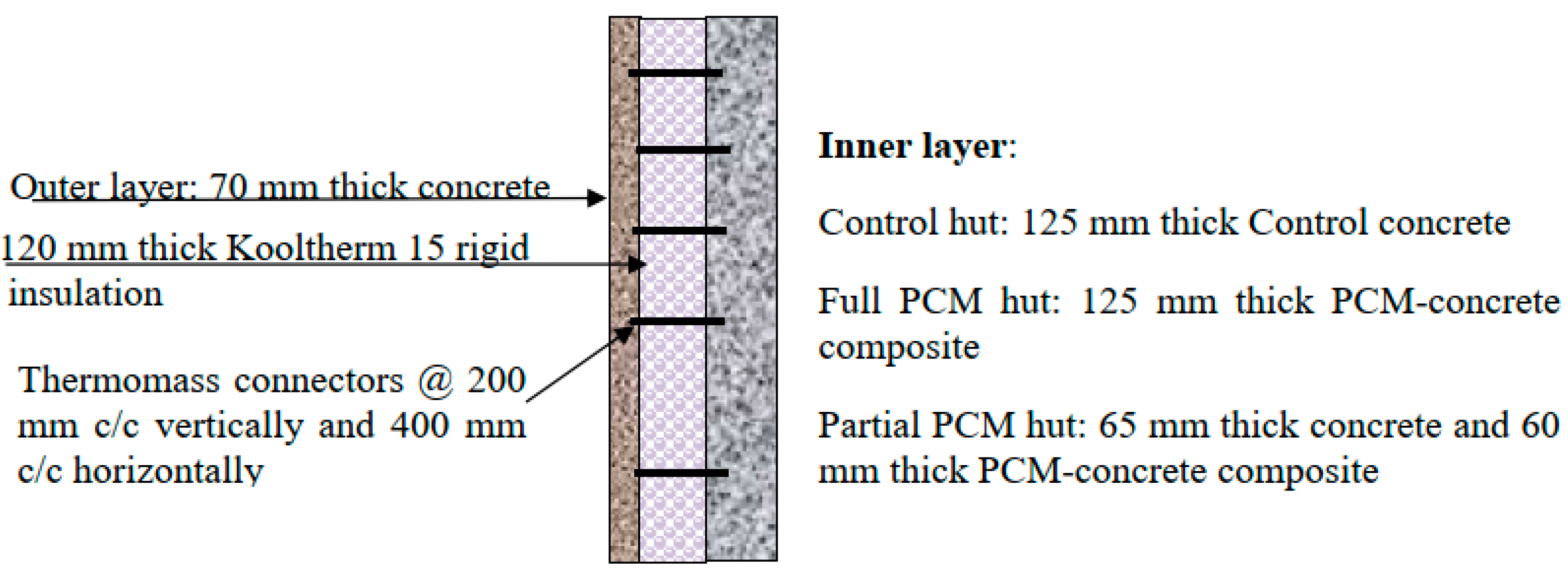
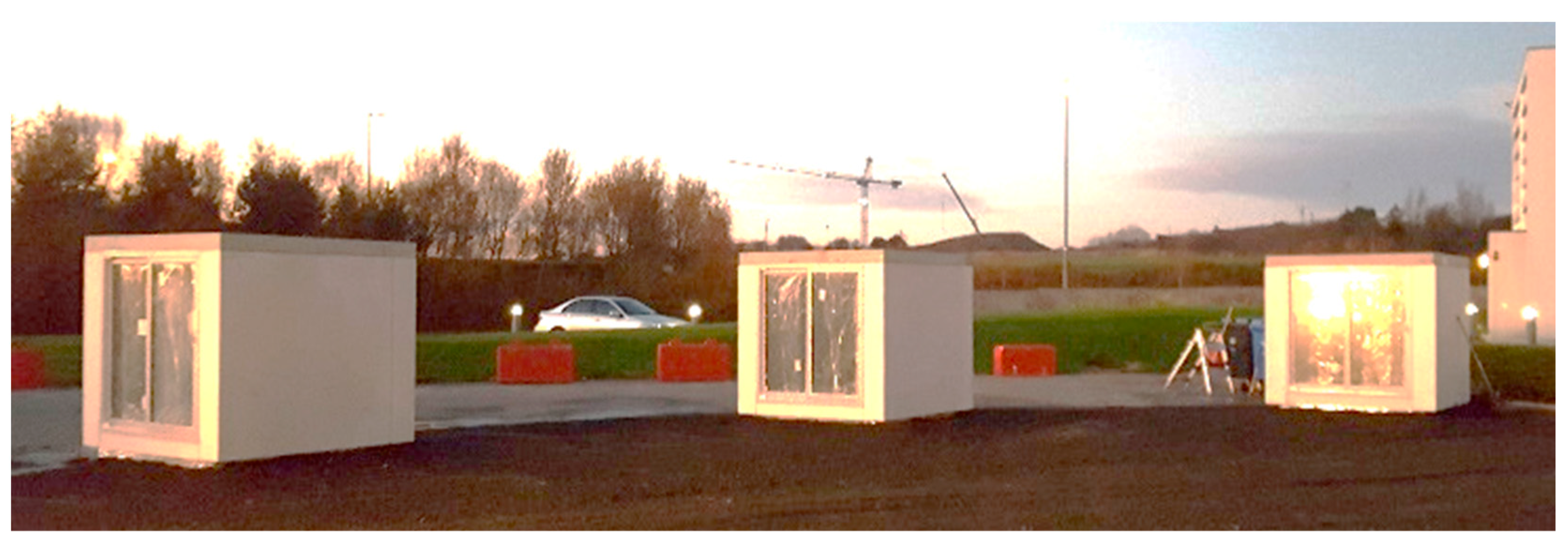
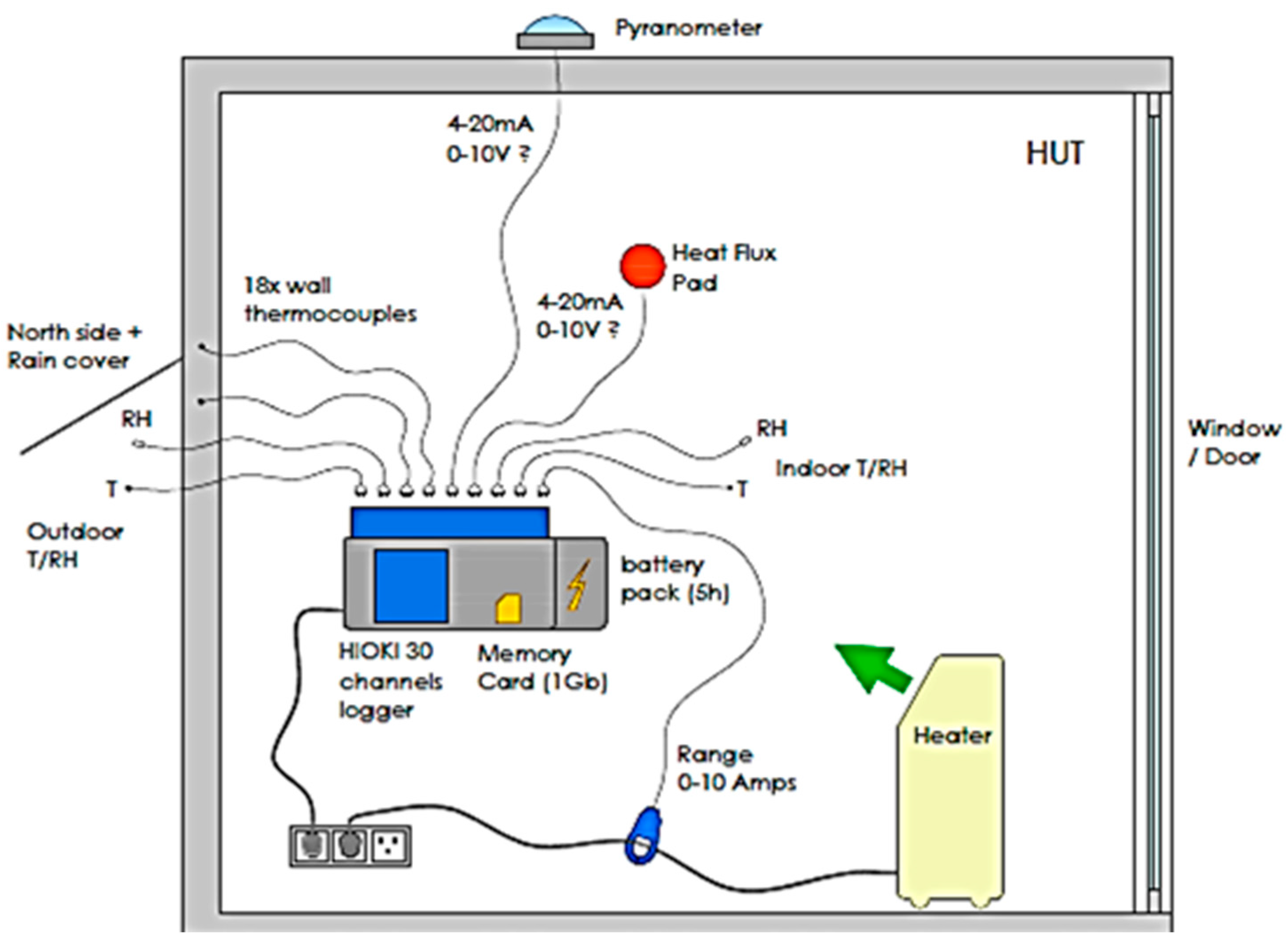
To build on the findings of Cabeza et al.’s research, in this study, three full-scale huts were constructed, two of which incorporated the novel PCM–concrete precast cladding panels (the third was a control panel hut with no PCM), which included a layer of insulation between the outer and inner leaves. All huts had one side fully double-glazed with a sliding door incorporated to allow access and solar gain. The huts were instrumented to record both internal thermal data and local climate data. Data were recorded over an 18-month period to ensure that the thermal performance of the panels could be assessed across all seasons. Thermal data were also recorded throughout the depth of the wall, which enabled the effective depth of the PCM to be determined under varying daily and seasonal thermal conditions.
As all buildings differ, each building will require a unique optimal solution for the application of a PCM composite material as a TES system. For this reason, the development of numerical simulation tools is necessary to achieve a practical and economic application of this technology. Coinciding experimental data, collected from full-scale tests within a real form of construction is required to validate a PCM numerical model. In the literature, most studies that investigated PCM composites within a full-scale setting were numerical simulations in which the model was validated using data from a laboratory study. There is a lack of modelling studies that have been validated against long-term results from full-scale experiments constructed using multiple layered walls and typical construction details [
4]. In this study, the data collected in the huts are used to calibrate a simulation model that can be used to accurately predict the response of the PCM composite in any full-scale scenario and any geographical location.
This study has furthered the field of knowledge regarding the thermal performance of PCM–concrete through the provision and analysis of a thermal data set collected within a real form of construction through all seasons together with the development of a novel and validated simulation model, which facilitates further research into this form of technology and the development of optimal bespoke solutions.
This research was part of a European-funded Horizon 2020 project titled IMPRESS, the details of which can be found at
https://cordis.europa.eu/project/id/636717 (accessed on 14 February 2024). The overall aim of IMPRESS was to develop innovative precast products for the renovation of existing building stock thereby improving the performance and energy efficiency of European buildings. Partners in this project include a leading concrete cladding company, Techrete Ltd. (Dublin, Ireland), and Sirus International (Dublin, Ireland), who provided the monitoring equipment in the huts.
3. Results
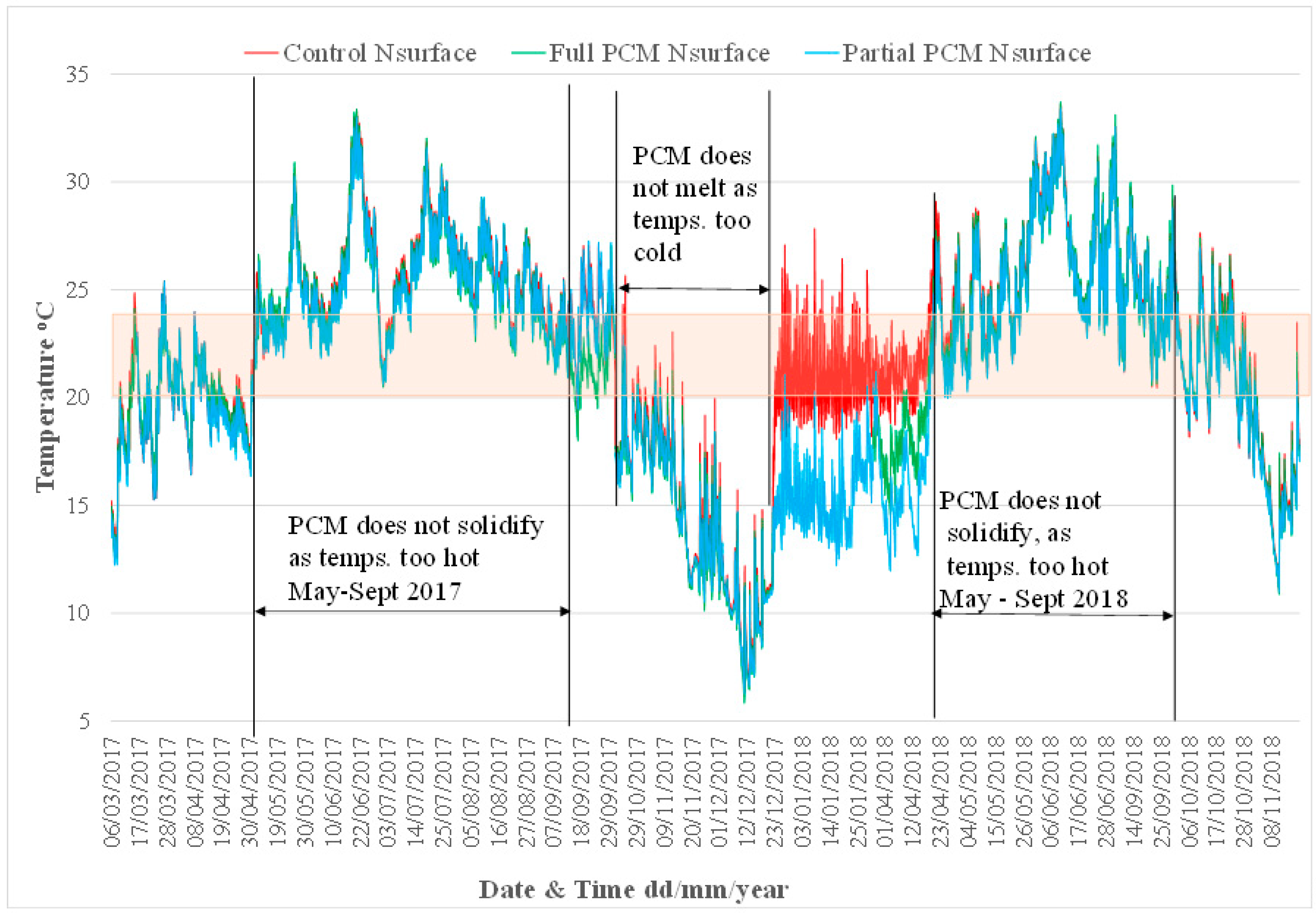
Environmental data were collected in each hut over an 18-month period. To obtain an overview of when the PCM was engaged throughout the year,
Figure 10 displays the temperature of the surface of the north wall in each hut over the full 18-month period. The melt temperature range of the PCM (20–24 °C) is shown as a shaded band. The plot identifies the periods during which the PCM was not active, either because the temperature of the hut walls was too high during the night to allow the PCM to solidify and release its heat, or because the wall temperatures did not get high enough during the day to cause the PCM to melt.
Overall, the data indicate that in passive conditions, that is, when the heaters are not switched on and no ventilation is provided at night, the PCM is only engaged circa 30% of the year, during the spring and autumn periods. A factor that contributes to the low engagement of the PCM is Ireland’s temperate climate. The mean daily temperature in Ireland ranges from 4 °C in winter to 16 °C in summer. Hence, the periods during which the internal temperatures in a building (in the absence of artificial heating) may rise above 22 °C are shorter compared with buildings within hotter climates. Although the PCM was ineffective for circa 70% of the study period during which passive conditions were applied, the application of various heat load regimes and ventilation strategies allowed the behaviour of the PCM to be more fully observed and analysed under varying nonpassive environmental conditions. In the following sections, data for scenarios of particular interest taken over shorter periods are analysed in closer detail.
3.1. Thermal Behaviour of Panels When PCM Is Not Engaged
As the PCM within the concrete matrix is only engaged for a certain percentage of the year, it is important to observe and compare the thermal behaviour of the PCM–concrete composite and the normal concrete when the PCM is either fully solid or fully melted over a full diurnal period.
During the winter months, in passive conditions, that is, when the heaters do not come on during the day, the internal wall temperatures in the huts often remain below the lower temperature of the PCM melt temperature range (20 °C). Similarly, in summer conditions, although the PCM melted, sometimes the huts did not cool down sufficiently overnight to allow the PCM to solidify. Under these conditions, the only difference between the huts is the thermal conductivity of the inner leaf material. The impact of this difference depends on the temperature differential between the internal and external environment. The insulation layer buffers the internal environment from fluctuations in the external air temperature. The glazed elevation also buffers the internal environment from fluctuations in the external air temperature, albeit to a lesser extent due to its higher U-value.
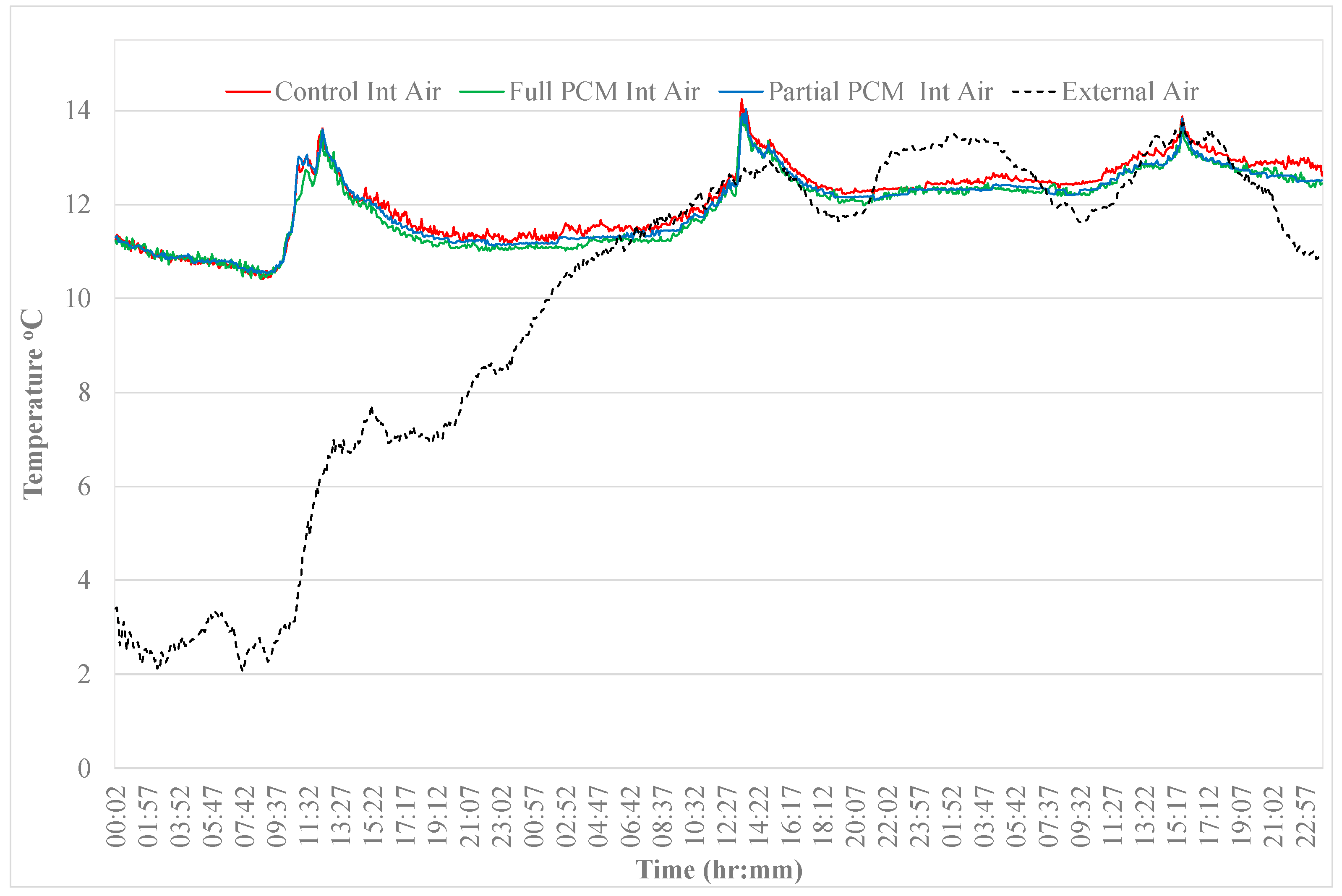
Figure 11 shows a comparison between the internal air temperatures of the huts during a three-day winter period. The peak air temperature remains at 14 °C or below, which is well below the melt temperature of the PCM. It can be observed that there is no significant difference between the internal air temperatures of the three different types of huts when the PCM is continuously solid throughout the period. During the latter two days of said period, the internal air temperature was similar to the external air temperature, so the temperature differential between the internal and external environment was relatively small. However, during the first day of the period, the temperature differential is greater at circa 7–8 °C, and it can be noted that the internal air temperature in all the huts follows the same profile, indicating that the walls of the huts have a similar overall thermal conductivity when the PCM remains in a solid state. The sharp rise in temperature that can be observed on each day is due to radiative heat transfer from the sun showing the effect of solar gain inside the huts.
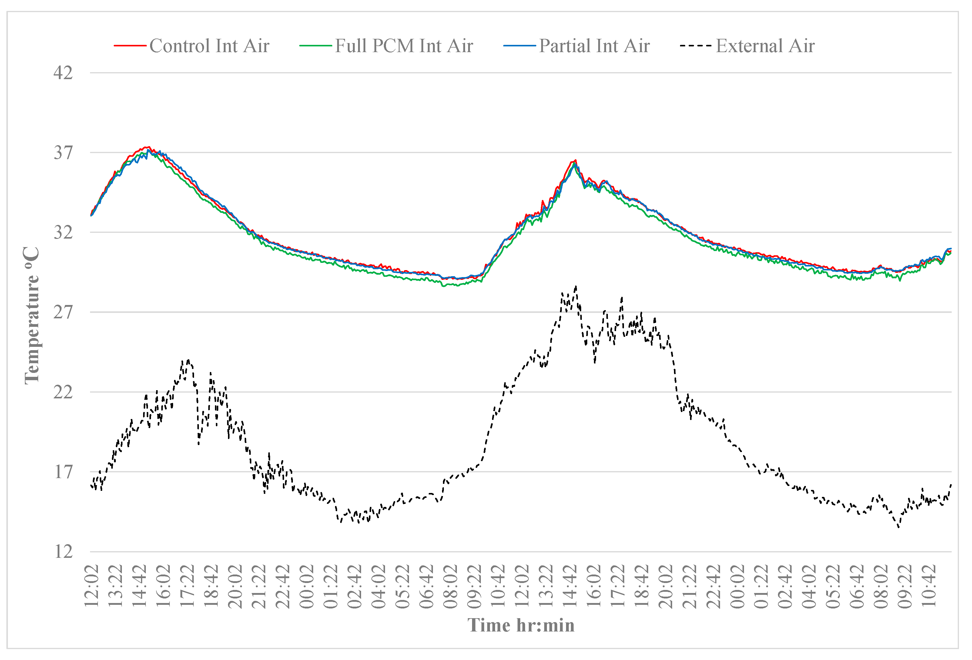
Figure 12 displays the internal air temperatures of the huts and the external air temperature during summer. The internal air temperature does not fall below 28 °C, even though the external air temperature falls to 15 °C; hence, it can be assumed that the PCM remains in a fully melted phase during this period.
As displayed in
Figure 12, the profile of the internal air temperature follows the profile of the external air temperature. However, the amplitudes of the internal air temperature profile are lower showing the effectiveness of the insulation layer and double glazing. It can also be noted from
Figure 12 that the temperature profile of the internal air in each of the huts is very similar indicating that the heat gain/loss through the walls and glazed elevations of the huts is the same despite the presence of PCM in two of them because the temperature differential between internal air temperature and the external air is the same for each hut.
It can be concluded that under the dynamic nature of the temperatures on either side of the walls and the relatively low temperature differential across the wall, the difference in overall thermal conductivity of the panels is not large enough to result in a significant difference in the rate of heat transfer through the wall and hence the thermal mass behaviour of the PCM–concrete composite panel is similar to that of the normal concrete panel when the PCM is either fully melted or fully solid.
3.2. Thermal Behaviour of Panels When PCM Is Engaged
To examine the influence of the presence of PCM in the walls of the huts under passive conditions, two periods were selected during which the wall temperatures fluctuated above and below the melt temperature range of the PCM, one during the winter season and one during the summer season.
3.2.1. Thermal Behaviour of Walls under Winter Passive Conditions
Data from the period from 9:00 a.m. 30 October to 8:55 a.m. on 2 November 2018 were selected and plotted to study the thermal behaviour of the walls under winter passive conditions. During this period, the temperatures in the huts increased above the melt temperature range of the PCM as a result of radiative heat from the sun, despite low external air temperatures. The internal air temperatures in each hut were similar at the start of this period, ranging from 15.1 °C to 15.5 °C. Also, the internal temperatures of the walls in each hut were very similar, both across the three huts and through the depth of each wall, ranging from 17.3 °C to 17.5 °C. As the wall temperatures at the start of the analysis are below 20 °C, it can be assumed that the PCM is in a solid phase throughout at the start of the analysis on 30 October.
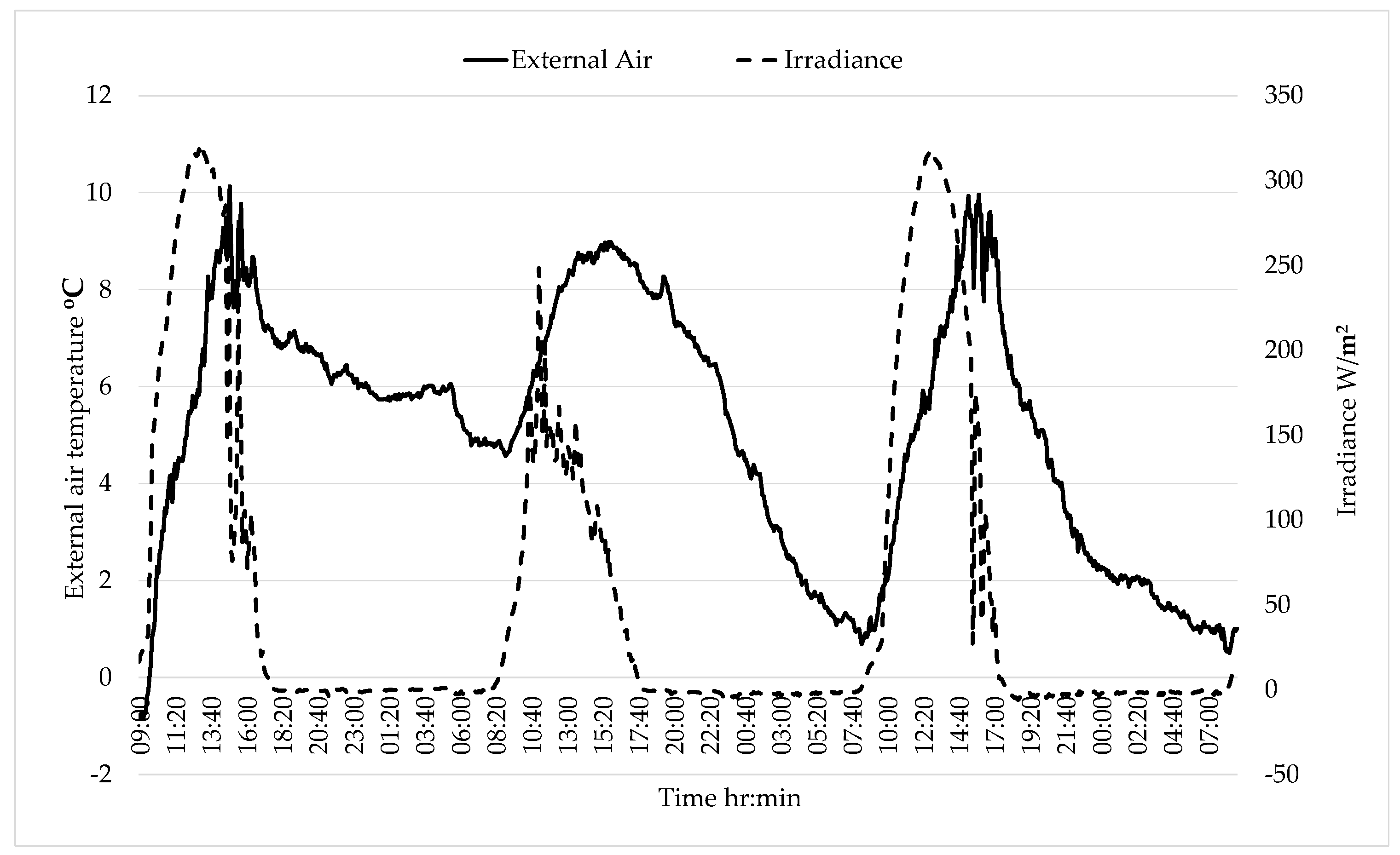
Figure 13 shows irradiance levels (up to 320 W/m
2) for the period together with the external air temperature (up to 10 °C).
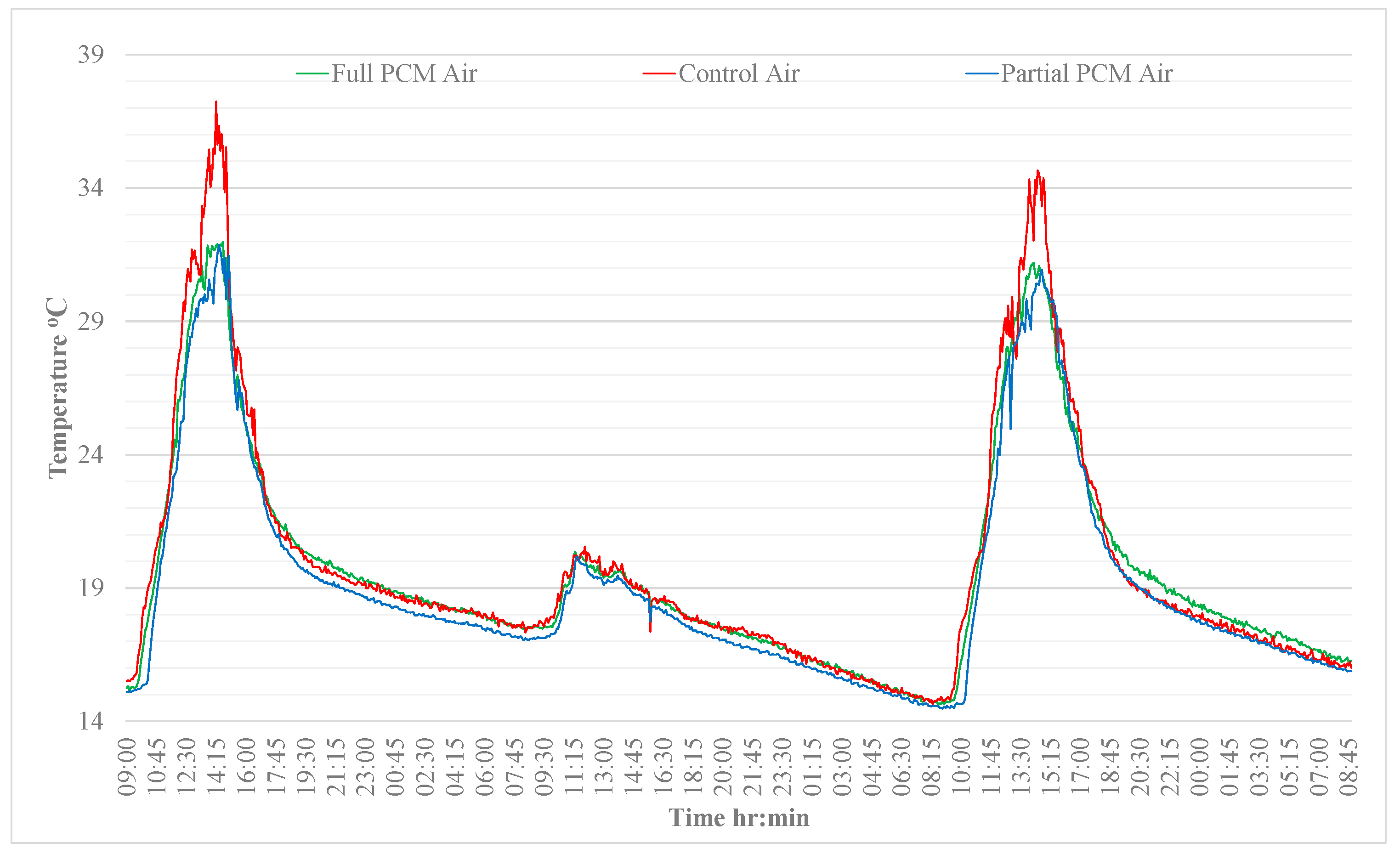
Figure 14 displays a comparison of the internal air temperatures of each hut over the said period. It can be observed that, although the rates of heating and cooling are similar in all the huts, the peak temperatures in the control hut on 30 October and 1 November are greater than the peak temperatures reached in the huts containing PCM. The peak internal air temperatures for each hut on the 30 October and 1 November are provided in
Table 3.
There is little difference (due to experimental variability) between the peak temperatures of both huts containing PCM; however, there is a significant difference between the peak temperatures in the PCM huts and the control hut of circa 5 °C on the 30 October and circa 3.5 °C on the 1 November, which indicates a 12% reduction in the peak air temperature of the PCM huts. It is interesting to note that peak internal air temperatures of over 30 °C were reached despite external air temperatures of less than 10 °C and no heaters being on in the huts, albeit being situated in a relatively small volume room and a well-insulated space. This highlights the impact of solar gain on the internal environment particularly when ventilation is not provided. The ability of the PCM to reduce overheating effects is clearly demonstrated.
On 31 October, the irradiance levels were much lower (
Figure 13), and the peak temperatures in all the huts were similar at 20.6 °C, 20.4 °C, and 20.2 °C in the control hut, Full-PCM hut and Partial-PCM hut, respectively. These temperatures are too low to activate the PCM.
3.2.2. Thermal Behaviour of Walls under Summer Passive Conditions
Data from the period from 9 a.m. on 9 June to 6 a.m. on 11 June 2017 were selected and plotted in detail to study the thermal behaviour of the walls under summer passive conditions. During this period, the air and wall temperatures in the huts fluctuated within and above the melt temperature range but did not drop low enough at night to cause the PCM to solidify completely because the external air temperatures were not low enough. However, it is of interest to examine the impact, if any, that the presence of PCM may have when the temperature is only fluctuating within the melt temperature range, so the PCM is only ever partially melted.
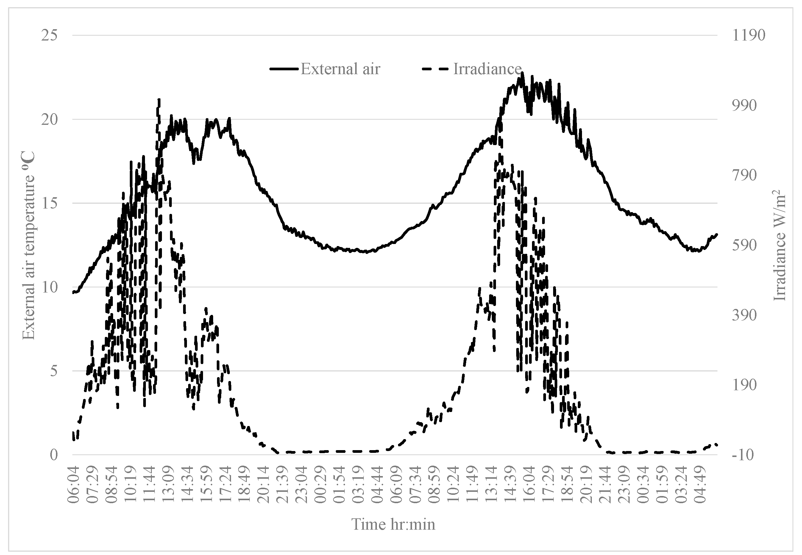
Figure 15 displays the external air temperatures and irradiance levels for this period. Overall, in comparison with the winter passive external conditions, the external air temperature overnight was on the order of 5 °C to 10 °C warmer, and the irradiance levels were significantly greater over a longer period during the day, not surprisingly.
Figure 16 displays the internal air temperatures in the huts on these days.
Table 4 provides the peak internal air temperature reached in each hut on each day. The internal air temperature profile in each hut was very similar with a peak air temperature in the control hut of up to only 0.6 °C greater than those reached in the huts containing PCM. The air and wall temperatures in the huts at the start of the period were circa 22.3 °C, which is greater than the onset melting temperature of the PCM. In these thermal conditions, it can be assumed that a large portion of the PCM is in a melted state at the start of the heating period and hence cannot provide any further latent heat capacity.
The peak internal air temperatures achieved in the control hut during summer passive conditions at 28 °C was less than that achieved during winter passive conditions at 34 °C, despite higher levels of irradiance occurring at the site during the summer dates. The heat gain in the huts is largely due to the absorption of the incident rays by the exposed concrete surfaces. The area of concrete surface that is exposed to solar irradiance is greater in winter, primarily on the walls due to the lower solar altitude angle. In summer, less irradiance enters the hut due to higher sun elevation, and it is primarily on the floor. In this research project, the floors have been thermally isolated with a layer of insulation, so the floor does not absorb any significant incident solar radiation.
3.2.3. Thermal Behaviour of Walls under Applied Heat Load with No Overnight Ventilation
To examine the influence of the presence of PCM in the walls of the huts when an artificial heat load is applied, data from the 1st and 2nd of May 2017 are plotted in detail. At the start of the period, the air and wall temperature in each of the huts were similar, that is, within less than 0.1 °C of each other. Also, the starting wall temperatures were circa 17 °C, so the PCM can be assumed to be solid throughout the walls. The heaters were set to come on between 8:30 a.m. and 3:30 p.m. each day, whenever the temperature fell below a set point of 20 °C, to simulate a typical heating pattern in, say, a school or working environment.
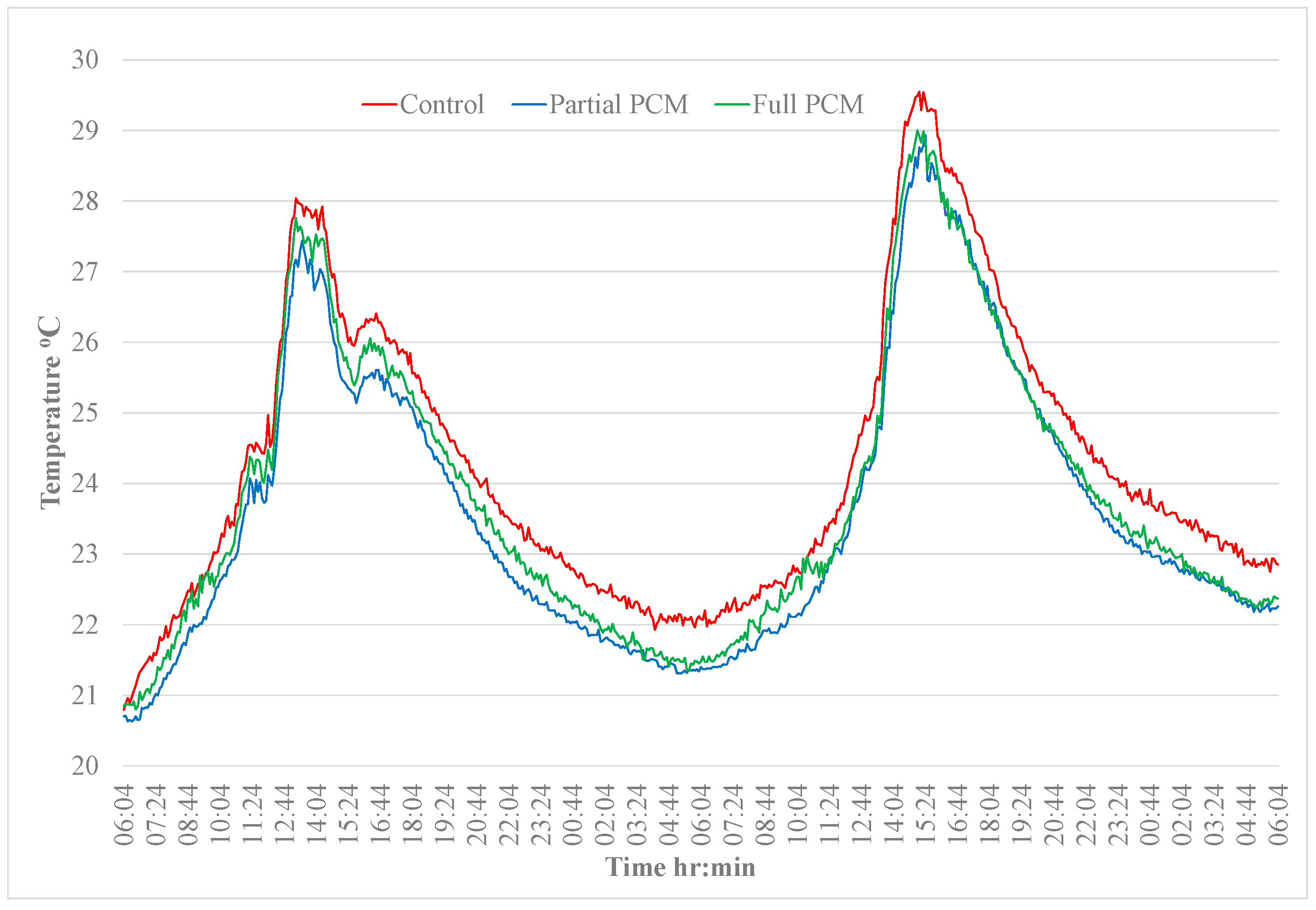
Figure 17 displays a comparison of the internal air temperatures of each hut over the two-day period. It can be noted from the figure that the temperature in the control hut increased to 27 °C when the heaters were on and then cooled to 19 °C overnight before increasing again on day two to 29 °C. During the heating period on the 2nd of May, the temperatures are slightly erratic; however, this can be attributed to variance in the solar irradiance on this day. The peak internal air temperatures for each hut are provided in
Table 5.
It can be observed that when the internal air temperature increases up to circa 28 °C, the presence of PCM results in an average reduction in the internal air temperature on the order of 1.0 to 1.4 °C, a modest amount. It is also interesting to note that the reduction in the internal air temperature in the PCM huts is slightly greater on the second day when the air temperatures are also slightly higher. The higher internal air temperatures lead to higher temperatures within the wall resulting in more melting of the PCM. From these observations, it can be concluded that the PCM within the walls is changing phase during the heating periods, which are approximately 8 h long, and hence somewhat reducing the peak internal air temperatures in the huts containing PCM. The rate of cooling is similar in all the huts.
3.2.4. Thermal Behaviour of Walls When Heaters Are on and Natural Overnight Ventilation Is Provided
It is clear from the data that during the periods when the internal air temperatures of the huts increase significantly during the day, often the internal temperature of the hut at night does not fall low enough to cause the PCM to solidify and release its stored heat. This means that the PCM does not have any latent heat capacity available to absorb the excess heat again the following day. In order to extend the effective period of the PCM throughout the year, the feasibility of ‘cooling’ the internal environment of the huts using natural ventilation overnight was investigated. The huts were heated during the day, from 9 a.m. to 4:30 p.m., by the radiators to simulate the summer overheating conditions. Natural ventilation was provided overnight by leaving the doors open 100 mm for a fixed period.
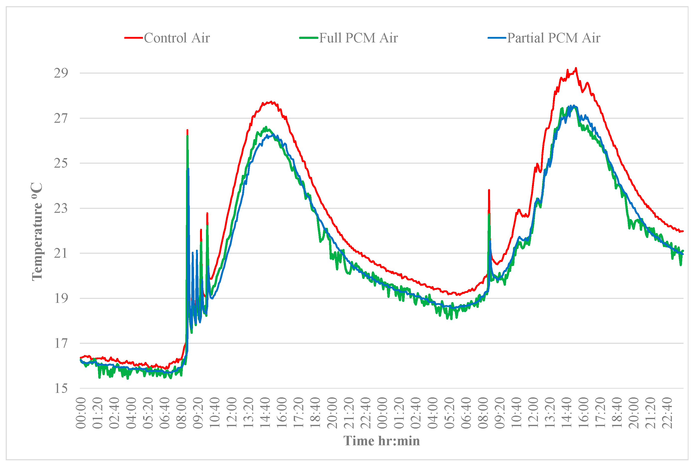
Figure 18 presents the internal air temperature in all three huts during a 24 h period from 24 to 25 October 2017.
When overnight ventilation was provided, the internal air temperature dropped to below 14 °C. The internal air temperatures in all the huts remained below 18 °C from 7 p.m. on the 23rd until 9 a.m. on the 24th. The temperature of the PCM–concrete composite throughout the whole depth of the wall was below 18 °C for circa 5 h during the night. Initially, the air temperatures oscillated as the heaters turned on and off around the set point. It can be noted that the air temperature in the control hut oscillated between 24 °C and 36 °C, providing an environment in which the PCM was expected to melt. During the cooling period, the air temperature reduced below the melt temperature range, hence facilitating the solidification of the PCM and the associated release of heat.
During the heating period, both huts containing PCM were consistently cooler, and the amplitude of the oscillations in air temperature was much smaller. During the heating period, the average temperatures were 28.7 °C for the control hut, 23.9 °C for the Full-PCM hut and 24.4 °C for the Partial-PCM hut. Hence, the Full-PCM hut and Partial huts were an average of 4.7 °C and 4.2 °C cooler than the control hut, respectively, which indicates a 16% reduction in peak air temperature. The temperatures in the huts with the PCM indicated that the PCM is melting and absorbing heat. There is no difference in the rate of temperature decrease during the cooling period, which is to be expected as the doors of the huts were open. This means that the influence of the external air temperature dominated the air cooling rather than the release of heat from the internal wall. On examination of the temperatures throughout the full depth of the walls in each hut, it was noted that the provision of overnight ventilation was successful in ensuring that the temperature of the entire wall thickness dropped below the solidification temperature. It was also observed that the PCM at depths greater than 60 mm in the Full-PCM hut reached temperatures to facilitate phase change, leading to slightly lower air temperature in the Full-PCM hut; however, the difference is not significant (0.5 °C).
3.2.5. Effective Depth of PCM
Throughout the data analysis, whenever the wall temperatures reached the melt temperature range of the PCM, the engagement of the PCM and its effectiveness at reducing the internal air temperatures was evident in both the huts containing the PCM–concrete composite. It can be noted from
Figure 14,
Figure 16,
Figure 17 and
Figure 18 that in all conditions there is no discernible difference between the internal air temperature profiles of the two huts containing PCM, which suggests that the additional PCM within the 60 mm to 125 mm depth of the Full-PCM hut is not significantly engaged in phase change activity. This result only applies to the environmental conditions analysed because a scenario that provided a greater temperature differential between the internal air and the wall over a longer period of time may lead to increased heat transfer into the wall and engagement of the PCM located deeper in the wall. The effective depth of PCM will be bespoke for a particular project and climate location and optimisation would require simulation modelling.
3.3. Validation of the COMSOL Model
In order to validate the COMSOL model, three 3D geometric models were created in COMSOL, one for each type of hut. The models replicated the geometry, orientation, and geographical location of the demonstration huts. The mesh size for the finite element model was automatically set by the COMSOL software in accordance with the physical behaviour under study. The PCM–concrete material parameters were modelled as described in
Section 2.4. Virtual probes were located in the model to coincide with the location of the thermocouples in the actual huts. Simulations were carried out on each hut for each time period as analysed in
Section 3.2. Conduction, radiative, and convective heat transfer conditions were included in the model. Given the number of probes and the complexity of the thermal behaviour being modelled, the computational cost of a simulation is relatively high. For this reason, the maximum time period to be simulated was restricted to 24 h. Each simulation was preconditioned by setting the initial temperatures of all the domains as per the actual temperatures recorded at the huts at the relevant point in time. The actual varying external air temperature recorded at the huts during the relevant period was imported as an interpolation function into the model and applied to the external boundaries of the hut model. Similarly, the actual irradiance recorded at the huts by the pyronometer was also applied to the model.
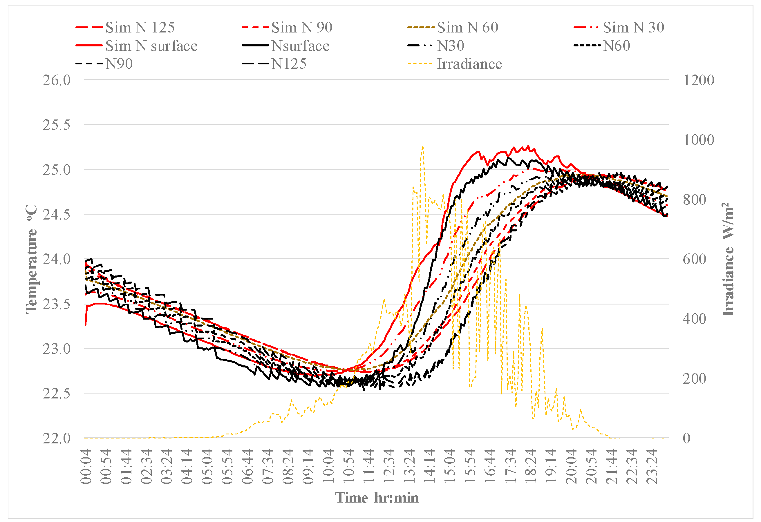
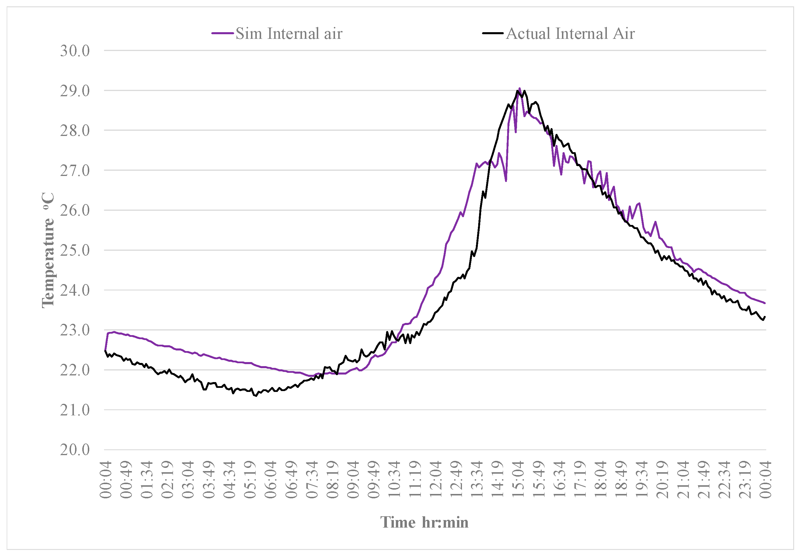
The wall and internal air temperatures simulated at each thermocouple location were plotted against the actual temperatures recorded at the hut for each hut during each time period. This resulted in 48 plots; hence, it is beyond the scope of this paper to review all of the simulation results. A sample of a plot comparing the actual and simulated wall temperatures in the Full-PCM hut is provided in
Figure 19, and a comparison of the internal air temperature is provided in
Figure 20.
To ascertain the accuracy of the simulation results, the absolute value of the simulated temperature (Tsim) minus the actual temperature (Tact), as recorded by the thermocouples, was calculated for each output at each thermocouple location. The average difference was calculated and denoted as ‘Average |Tsim − Tact|’. To determine the precision of the Average |Tsim − Tact| data, the standard deviation of each set of temperatures simulated at each thermocouple location was determined by calculating the square root of the variance of each data set. The variance of each data set was found by subtracting the Average |Tsim − Tact| from each data point in the set, |Tsim − Tact| and squaring the result.
The variance is the average value of these squared values, that is,
The results of the statistical analysis of the data are summarised in
Table 6. The values for Average |T
sim − T
act| for each wall in a particular hut were averaged. The overall change in temperature in the walls and internal air, that is, the difference between the lowest temperature and the highest temperature, that occurred during the relevant time period is also noted, as it is expected that a larger temperature difference will result in a higher value for the Average |T
sim − T
act| as the difference between the simulation and actual results may accumulate.
It can be noted from
Table 6 that the accuracy of the simulations when the PCM was both engaged (10 June 2017) and not engaged (21 June 2017) was similar for both types of huts when the magnitude of the difference between the lowest and highest temperature in a particular hut, ΔT, was similar, that is, from 7.0 °C to 7.5 °C for the air and from 2.2 °C to 2.4 °C for the walls, indicating that the thermal behaviour of the PCM–concrete was being modelled with similar accuracy whether phase change occurs or not. It can also be noted that the accuracy of the simulations carried out on the same day was similar for the control concrete hut and the Full-PCM hut, indicating that the thermal behaviour of the PCM–concrete was being modelled with similar accuracy as the normal concrete.
The thermocouples used to measure temperature in the huts had a calibrated accuracy of ±0.86 °C. With the exception of the data set measuring internal air on 1 November 2018, all values for Average |Tsim − Tact| were below 0.86, indicating that the COMSOL model simulates temperatures with similar accuracy as the thermocouples used in the huts. All simulations displayed good accuracy in the initial phase of the simulation prior to the start of the heating phase when the applied irradiance started to enter the hut. The difference between the simulation and actual temperatures increased during the heating phase and subsequent evening cooling phase, albeit while remaining acceptably low. This is expected as the complexity of the model increases with the introduction of irradiance and convection effects as the air heats up.
The graphical and statistical comparative analysis carried out on the results of the COMSOL model simulations of various environmental conditions demonstrated the validity of the developed COMSOL model. The results obtained from the simulations were aligned with the real temperatures recorded in the huts and hence the model can be used to reliably predict the thermal behaviour and impact of the PCM–concrete in a ‘real-world’ full-scale scenario. The model can be used to observe and quantify any effects of using the PCM–concrete in various global locations and environmental conditions and for different geometries.
4. Discussion
From the analysis of the thermal data collected at the huts presented in
Section 3, one of the key findings is that the thermal conditions within the depth of the wall that would provide the potential for the PCM to change phase only occurred during 30% of the year. It is important to note that this outcome is related both to the form of construction and the local climate. The cladding panels included a layer of insulation as is typical in buildings in Ireland. This layer of insulation hinders the ability of the inner leaf to release its heat overnight, and the PCM to solidify as heat loss can only occur from the inner surface of the wall. This means that the rate of decrease in temperature of the internal air in the hut may be relatively low and hence the temperature differential between the wall and the internal air is also relatively low. A compounding factor is the temperate Irish climate. In summer, the external temperatures, level of irradiance, and the length of the daylight period are high enough to increase the internal temperatures above the melt temperature range of the PCM; however, the overnight temperatures do not drop low enough for long enough to facilitate the solidification of the PCM throughout the walls. It is expected that if the PCM–concrete composite was located in a form of construction that included less insulation and also in a climate which provided greater fluctuation in the diurnal temperature for longer periods during the year, it would have a greater impact on reducing overheating in internal environments of buildings.
It can be concluded from the thermal data analysis that the impact that the presence of a PCM–concrete composite has on reducing overheating varies considerably between each of the scenarios analysed. In order to compare the performance of the PCM–concrete composite across the various environmental conditions,
Table 7 provides a summary of key factors and outcomes under each scenario analysed. The peak temperatures reached in the control hut in each scenario are provided along with the length of the heating period. Another factor which is of interest is the temperature difference between the internal air and the internal temperature within the wall. The greater this temperature differential is, the greater the rate of heat transfer between the air and the wall. These factors are provided for in the control hut as an indication of thermal behaviour in the absence of PCM.
Table 7 also summarises the key metrics of the performance of the huts containing PCM–concrete composite, that is, the reduction in peak internal air temperature relative to the control hut. The temperature range of the PCM–concrete material within the walls from the start of the heating period to the end of the heating period is also noted.
It can be noted from
Table 7 that under summer passive conditions, the PCM–concrete composite has no significant impact on the internal air temperature, despite the internal air temperature in the huts reaching 28 °C. This result can be attributed to the higher temperature of the PCM–concrete composite at the start of the heating period, which would indicate that the PCM was only partially solid at the start, so its ability to absorb heat through phase change was limited. Also, the average temperature differential between the internal air of the control hut and internally within the wall was relatively low at 1.9 °C. In contrast, during winter passive conditions, the PCM can be assumed to be fully solid at the start of the heating phase, and the wall temperatures increase to 2.5–3 °C above the onset melt temperature. The average temperature differential between the wall and the internal air temperature in the control hut is significantly greater than the differential during summer passive conditions at 9.3 °C. These conditions result in a reduction in peak internal air temperature of approximately 4.5 °C—12% of the peak temperature in the control hut, which is quite significant.
It can also be noted from
Table 7 that the PCM–concrete composite was equally effective during winter passive conditions and nonpassive conditions with overnight ventilation. Under winter passive conditions, the PCM–concrete composite reached higher temperatures that extended further into the melt temperature range of the PCM and did not lead to greater effectiveness at reducing internal air temperatures. This could be due to the shorter heating period under winter passive conditions and also that as the main heat source under passive conditions is solar irradiance, the volume of PCM–concrete composite that reaches the peak temperatures noted is likely to be lower as the solar irradiance does not reach all the wall surfaces. However, when an artificial heat load is applied, the primary source of heat is the internal air which is applied evenly over the full surface area of the wall and hence engages a higher volume of PCM.
With regard to the effective depth of the PCM, although the data provided some evidence of phase change in the PCM at depths greater than 60 mm under nonpassive conditions, it was relatively minor and did not impact the internal air temperature. Hence, for reasons of economy, there is a justification for specifying PCM only within the first 60 mm of the internal wall depth. This result only applies to the environmental conditions analysed as a scenario that provided a greater temperature differential between the internal air and the wall over a longer period of time, which may lead to increased heat transfer into the wall and engagement of the PCM located deeper in the wall.
The conclusions of these analyses highlight the multitude of factors that influence the effectiveness of the PCM–concrete composite in reducing internal air temperatures. The data clearly show that the inclusion of PCMs into concrete is an effective if limited strategy for reducing overheating effects in a building and hence the demand on cooling systems under certain thermal conditions. The PCM–concrete composite was effective at reducing internal air temperatures by over 4 °C during winter passive conditions and when a heating load was applied with the provision of overnight ventilation. A key factor in the effectiveness of the PCM composite is the relatively high average temperature differential between the internal air and the PCM composite material in the wall during the heating period, circa 8–9 °C. Another critical factor is the temperature differential between the internal air and the wall material during the cooling period, which must be sufficient to facilitate complete solidification of the PCM overnight. During winter passive conditions, sufficient temperature differential for cooling was provided by the low external temperatures, which were below 10 °C all the time, while the applied heating period through irradiance was only circa 5 h. Under the applied heat load, a sufficient temperature differential during the cooling period was provided through natural ventilation. It can be concluded from the analyses that the provision of a suitable overnight ventilation system would extend the annual period during which the PCM is effective.
The graphical and statistical comparative analyses carried out on the results of the COMSOL model simulations of various environmental conditions demonstrate the validity of the developed COMSOL model. The results obtained from the simulations are aligned with the real temperatures recorded in the huts, and hence, the model can be used to reliably predict the thermal behaviour and impact of the PCM–concrete in a ‘real-world’ full-scale scenario. The model can be used to observe and quantify any effects of using the PCM–concrete in various global locations and environmental conditions and for different geometries.
5. Conclusions and Further Research
Overall, this research study has demonstrated that a PCM–concrete composite can successfully provide enhanced thermal mass benefits but with limitations. This study has furthered the knowledge in this field of research in a number of areas. Prior to this study, there was only one previous (short-term) study [
43] which assessed PCM–concrete in a full-scale scenario. In this previous study, the test huts were constructed using a single leaf wall and thermal data were only recorded over three weeks, so the findings are limited to the form of construction and the environmental conditions that existed during the limited test periods.
The key contributions of the research described in this paper are as follows:
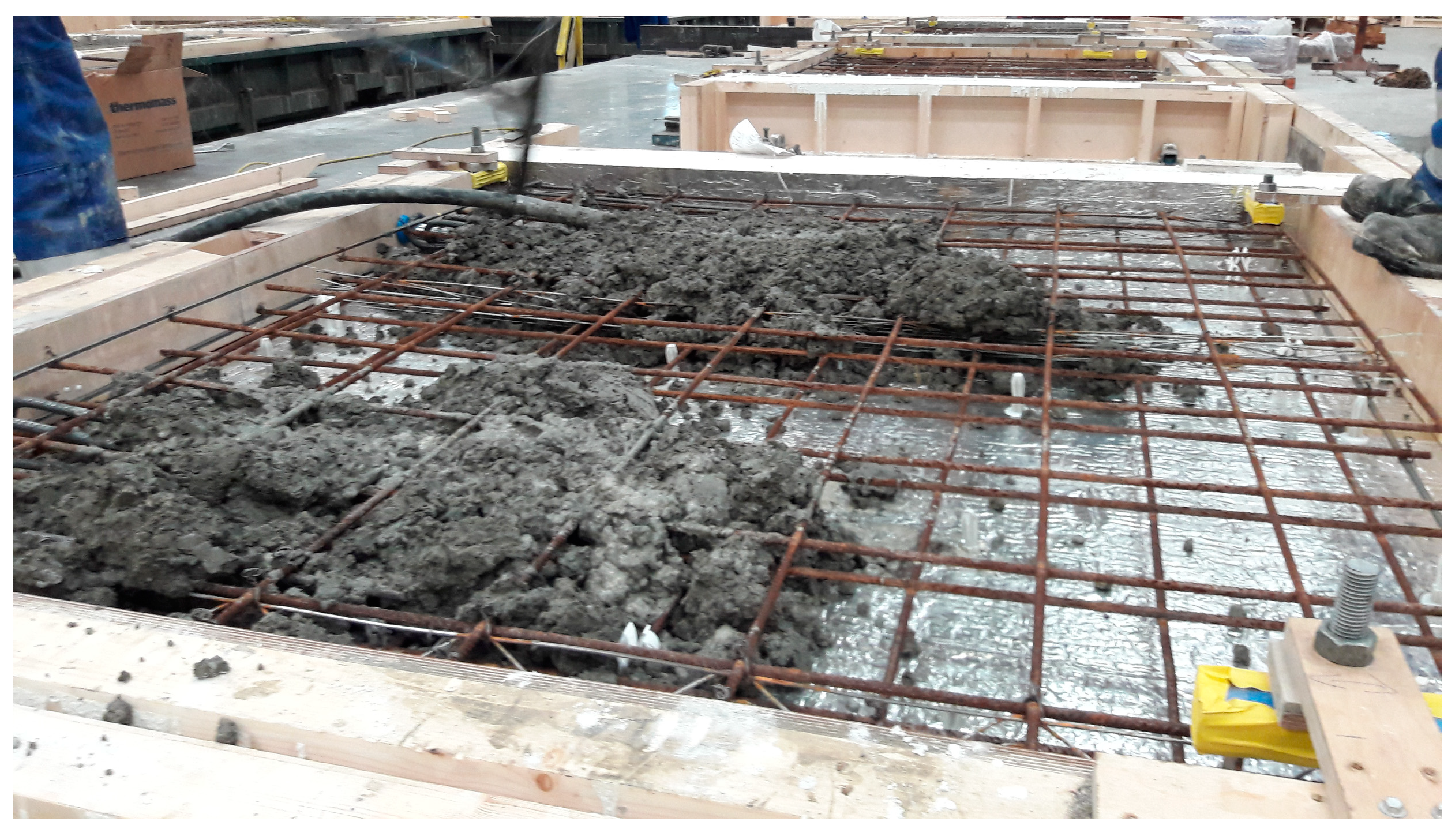
It has been demonstrated that PCM–concrete can be successfully upscaled for use in real construction projects using standard manufacturing methods.
A thermal data set was collected within a ‘real’, full-scale form of construction throughout all seasons, which enabled the impact of this form of technology to be realistically assessed across a full annual period.
This research study exposed the seasonal effect on the potential benefit of this technology. Analysis of the data set highlighted that the PCM only provides beneficial effects during circa 30% of the year in environmental conditions similar to an Irish climate.
PCMs located at depths greater than 60 mm within the wall were ineffective. This finding is specific to the local climate conditions and geometry of the huts; however, it highlights the order of magnitude of the effective depth of PCM concrete and the factors that influence it.
A simulation model was successfully developed to predict the thermal behaviour of PCM–concrete, which was validated using a data set collected from a real form of construction during all seasons.
The achievement of beneficial thermal mass effects is influenced by many variables, including geographic and building-specific characteristics; hence, it is important that the performance of PCM–concrete is assessed under full-scale and realistic building conditions. However full-scale experimental studies are significantly constrained by the cost of the necessary resources and time, and the results cannot be assumed to apply universally. To expand the understanding of this technology, calibrated modelling tools are essential. The development of the simulation model in this study facilitates bespoke solutions to be developed for any geographical location and building geometry, with optimisation of parameters including phase change temperature, latent heat capacity, effective depth, and location of PCM–concrete composite. The annual thermal data set allowed the model to be validated using data collected in a real form of construction. This has furthered the knowledge in the field of research because any models developed in previous research studies were only validated using limited data collected in a laboratory setting. The ability to simulate the thermal behaviour of a PCM–concrete composite will enhance research into this form of technology and make its use more accessible.
One of the main limitations of this technology is that the PCM may only provide beneficial effects during a portion of the year. The economic benefit of the technology is not only subject to the bespoke application of the technology for a particular building but also to the type and cost of the local energy provided to the building and hence can only be assessed on a case-by-case basis.
Another limitation that must be considered in the application of this technology is that to gain the thermal mass benefit of the PCM–concrete, the material must be left exposed within the building. This requirement may not align with architectural intent and may cause challenges in the installation of mechanical and electrical services to the building.
This research study has highlighted some areas of particular interest for further study as follows:
The simulation model could be used to investigate the performance of PCM–concrete placed in a typical room with concrete floors, walls, and ceilings in various climatic regions across a whole year period to determine an overview of which geographical locations and seasons would potentially benefit most from this technology.
The performance of the PCM–concrete composite is also influenced by the ratio of the exposed surface area of the PCM–concrete elements and the enclosed volume of air within the space. Further research could be conducted to investigate if there is a limit to this ratio at which the PCM–concrete ceases to be effective.
There are some limitations to the simulation model developed in this study, in that it does not simulate the effects of occupant behaviour, and it also assumes complete air tightness. The model could be developed further to allow other factors that influence the internal thermal environment in a building to be incorporated.

