Article

Multi-Port Energy Router in Mobile Energy Storage for Emergency Power Outage in Urban Cities

1
School of Physics, Engineering and Technology, University of York, York YO10 5DD, UK
2
Faculty of Engineering and Sciences, King’s College London, London WC2R 2LS, UK
3
School of Information and Electronic Engineering, Shandong Technology and Business University, Yantai 265600, China
4
Department of Electrical Engineering, College of Engineering, University of Bisha, P.O. Box 551, Bisha 61922, Saudi Arabia
*
Author to whom correspondence should be addressed.
Energies 2024, 17(12), 2927; https://doi.org/10.3390/en17122927
Submission received: 19 May 2024 / Revised: 5 June 2024 / Accepted: 12 June 2024 / Published: 14 June 2024
(This article belongs to the Special Issue Control Strategies of Energy Storage Systems in Microgrids)

Abstract

:
A multi-port energy router (MER) is an important infrastructure for power management and energy storage after an unexpected power outage. In addition, MERs can relate to various emergency electric power sources (EEPSs) and power grids at the same time. Moreover, by putting an MER in mobile energy storage, an MER allows for more flexible energy management and regulation in urban cities. This paper proposes a new topology of MERs composed of a bidirectional AC/DC converter and a partial power processing-based triple active bridge (PPP-based TAB) converter to supply emergency power for an unexpected power outage. This design of an MER improves the power efficiency significantly to realize peer-to-peer (P2P) trading which realizes the bidirectional power transmission among the main power grid, EEPSs such as the battery of electric vehicles (EV), and clients’ loads. The control methods of the power transmission of two power electronic converters in MER are also illustrated in this paper to realize the power transmission among the main power grid, clients’ loads, and EEPSs. This allows any power source connected to the MER to be used as an input or output to receive or send out power, which greatly improves the utilization of power. In conclusion, the MATLAB/Simulink and experiment test are executed and meticulously presented to validate the practicality of the proposed configuration.

1. Introduction

There are many unexpected events impairing the urban power grid leading to power outages, with severe safety consequences such as the snow disaster in China [1], the accidental failure of the dam’s power supply system in north-eastern Brazil [2], the major blackout in India [3], and the 24 h power outage because of some fatal social events in New York [4]. Virtually every sector relies on electricity to operate the necessary electrical equipment, as electricity serves as a fundamental component in various aspects of human life. Hence, the power outages create serious problems impacting daily life in society as well as major issues in industrial sectors causing economic loss and risking lives [5]. To break down the details, first, the most direct impact is damage to the power grid equipment with safety issues, loss of materials, and financial and time resources to repair and rebuild the system [6]. The other indirect impact is an inconvenience on society’s life and operation [7]. Moreover, a power cut can also be life-threatening in specific locations such as hospitals [8].
In view of the above, in the event of an unanticipated power outage, it becomes imperative to mitigate these losses. Up to this point, emergency power sources and their associated distribution techniques, which will be elaborated upon in detail in [5], have been regarded as effective solutions. To date, two prevalent methods for emergency power distribution, namely, distributed power [9] and emergency power vehicles [10], have found widespread use. However, there has been a recent introduction of an alternative approach to emergency power distribution in the form of an energy router. This method has been proposed and demonstrated with several distinctive features [11]. This approach can apply multiple types of different EEPSs as input at the same time, which is different from the current emergency power systems [12]. Furthermore, its applicability extends to the smart power grid and microgrid environments [13]. Given its capabilities, such as efficient energy utilization, versatile power sources, energy storage, and the ability to monitor the condition of the primary power grid, the energy router is well suited to serve as a power source within smart power grids and microgrids. A lot of power sources have the potential to be a new kind of EEPS [14,15]. Moreover, the battery of an EV as a new potential EEPS can be connected more easily and conveniently with an energy router to achieve high power management [5].
Compared with two current distribution ways, an MER enables connection to multiple power sources for real-time and efficient energy management. In this paper, the proposed MER consists of a bidirectional AC/DC converter and a PPP-based TAB converter shown in Figure 1. The bidirectional AC/DC converter is used to realize the transfer of AC power in the main power grid into DC power to make sure the power transmission in the PPP-based TAB converter is in the normal situation. When the main power grid lacks power, a bidirectional AC/DC converter can change the direction of power transmission to meet the demand for power supply to the main grid over a period. This means that the power grid will no longer be the power supply only, which realizes efficient energy management, increased energy efficiency, and P2P trading technology [16,17].
In addition to fulfilling the role of emergency backup power, large-capacity mobile energy storage also possesses the flexibility and ability to regulate energy over long distances to meet different power demand scenarios [18]. By mounting the MER on mobile energy storages, emergency power can be provided to any power outage area regardless of time and location. Also, the required power for various temporary events such as concerts, sports events, construction sites, and temporary medical facilities can be supplied [19]. In addition, during periods of peak demand in cities, high-capacity mobile energy storage can be used for peak shaving, helping to maintain grid stability and reduce reliance on traditional energy sources such as fossil fuels [20]. In addition, the battery of an EV can also be considered as a mobile EPPS to relate to the large-capacity mobile energy storage [21]. Combining the large-capacity mobile energy storage and the battery of an EV makes sure the emergency energy supply is fully prepared in all cases.
Partial power processing (PPP) is a technology that uses converters to process part of the total power, while most of the unprocessed system energy is transferred directly through the power cables [22]. Power dissipation can be reduced as the PPP converter processes less power, which has the effect of improving system efficiency and power density [23]. Furthermore, previous research has developed other PPP converters incorporating flyback converters [24], dual-active bridge (DAB) converters [25], and quasi-Z-source converters [26] based on their equivalent full-power isolated converters. With the merits of high energy conversion efficiency, the PPP multi-port converters have a promising future and deserve further research in topology design and application, especially for the multi-port energy routers. With regard to MERs, the PPP multi-port converters facilitate the transfer of power in a more efficient manner by enabling bidirectional energy flow between the ports [27]. Furthermore, they facilitate the control of power flow with greater ease.
In terms of the DC power transfer part in the energy router, a PPP-based TAB converter is proposed in this paper. The proposed converter has three ports, and power is exchanged between them using a phase-shift pulse-width modulation (PWM) mechanism [28]. Based on the lag/lead relationship of three pulse width waveforms, ports at PPP-based TAB converters can realize the power transmission. With different lag/lead relationships, the directions of power transmission are also various because each port of a PPP-based TAB converter can ensure the bidirectional power flow [29]. This method permits the charging and discharging of energy between ports while maintaining the high-efficiency advantages of the PPP converter [30].
With this topology of MER, demand for electricity can still be met even in the event of an unpredictable power outage. In addition, the proposed MER also interconnects the various forms of power supply, allowing them to exchange energy and at the same time ensuring the stability of the whole system. This paper is structured as follows: First, the configuration and power flow control methods of the bidirectional AC/DC converter are briefly described. Secondly, the PPP-based TAB converter is demonstrated. Thirdly, a simulation model containing the proposed MER is implemented in MATLAB/Simulink. Fourthly, an experiment of a PPP-based TAB converter is verified. A conclusion is given at the end of this paper.

2. Topology Configuration

2.1. Bidirectional AC/DC Converter

Figure 2 presents the bidirectional AC/DC converter structure. The proposed topology has two ports, each of which is connected separately to the main power grid and one port of the PPP-based TAB converter. The bidirectional AC/DC converter involves a full bridge with four switches, an inductor Lad, and a capacitor Cad. Among them, the inductor Lad is an important factor that makes sure that the bidirectional AC/DC converter works in the continuous conduction mode (CCM) and determines the size of the input current ripple. Furthermore, the main functions of capacitor Cad are mainly in two aspects. One of them is the filtering of voltage ripples caused by the high-frequency switching action of switches. The other is keeping bus voltage fluctuations within limits and supplying the load while the bidirectional AC/DC converter is operating in inductive energy storage.

2.2. PPP-Based TAB Converter

The depicted configuration, as illustrated in Figure 3, features three ports. Each of these ports comprises an inductor Lx (where x is 1, 2, or 3), a transformer with winding Nx, and an H-bridge equipped with four switches. Furthermore, capacitors Cy (where y is 1 or 2) at ports 2 and 3 are connected in parallel with their respective H-bridges. Additionally, any type of EPPS ES is connected to port 2 through wiring, establishing a circuit for charging and discharging. Port 1 relates to the DC port of the bidirectional AC/DC converter to enable a grid connection of the ER to the main power grid. Port 3 is connected to the clients’ loads and the energy router storage unit (ERSU) to realize the power supply for loads. In an MER for an emergency energy system, ES can be assumed to be any kind of EPPS which is explained in detail in [5]. In this design, part of the power is transferred between the three ports through the three windings, while the remaining power travels directly from the input port to the output port. This approach, unlike traditional DC/DC converters, integrates multiple ports to accommodate diverse bidirectional power flow needs. The system can also be flexibly integrated into a multi-port bidirectional energy router to conserve space, utilizing a distributed ERSU. Under normal circumstances, which is in grid connection, the main power grid at port 1 is the input and supplies power to port 2 and port 3. ES and ERSU at port 2 and port 3 are the output and receive power. In addition, according to the state of charge (SOC) of ES and clients’ needs, ES at port 2 can also be changed into input and supply power to the loads and ERSU at port 3 with the main power grid at port 1.

3. Control Method Analysis

3.1. Bidirectional AC/DC Converter

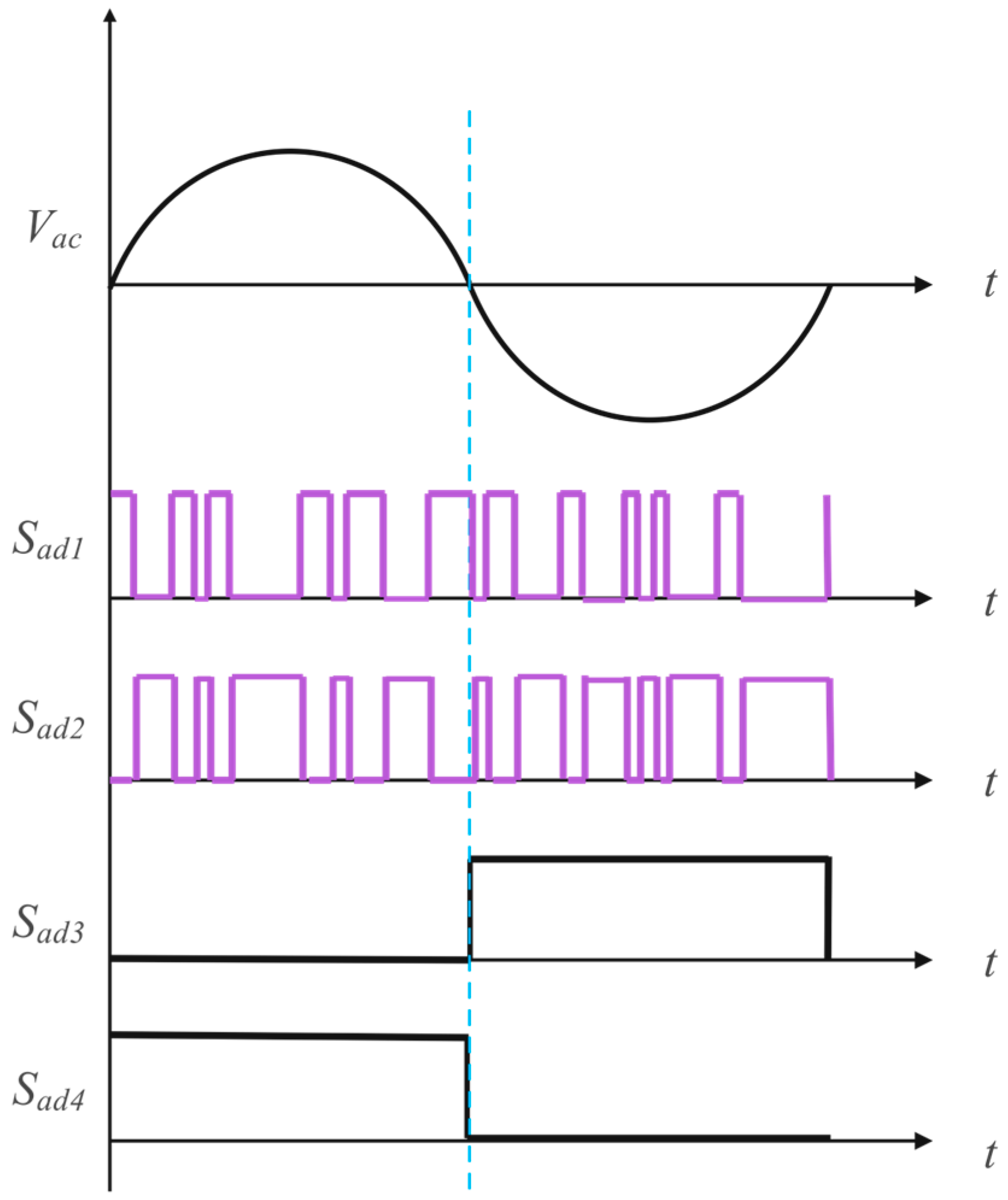
In this paper, a full bridge circuit structure consisting of four MOSFET switches is used as the main circuit structure for the bidirectional AC/DC converter, thus enabling the bidirectional flow of energy. The control of the four MOSFET switches allows the bidirectional AC/DC converter to always provide a constant and stable output voltage. For bidirectional AC/DC converters in rectifier mode converting AC power to DC power, when the voltage at the AC port is positive, switch Sad3 is always off and Sad4 is always on, while switches Sad1 and Sad2 operate at high frequencies shown in Figure 4, thus contributing to a Boost circuit with the AC input side inductor Lad. Sad2 is the main switch and Sad1 is the current continuity switch. When Sad3 is on and Sad1 is off, the inductor charges and stores energy. When Sad1 is on and Sad2 is off, the inductor discharges and releases energy to the DC port, thus completing the conversion from AC power to DC power. When the voltage at the AC port is negative, a similar operation to the positive half-cycle can be obtained. When the topology is in the inverter mode, which converts DC power to AC power, the four switches form a Buck circuit in the positive and negative half of the power grid, transferring the energy from the DC side to the AC side. This means that Sad3 and Sad4 are always on or off during the positive and negative half-cycle of the AC voltage, while the high-frequency switches Sad1 and Sad2 work as the main switch and continuity switch of the Buck circuit, respectively, thus realizing the inverter function.
For the control of switching tube gate signals, the phase-locked loop (PLL) technique is used in this bidirectional AC/DC converter. PLL is a phase feedback system that obtains the instantaneous phase of a time-varying sine wave. The basic PLL consists of three modules, the phase angle detector (PD), the loop filter (LF), and the voltage-controlled oscillator (VCO) [31]. This topology uses a PLL based on the second-order generalized integrator (SOGI) shown in Figure 5. This PLL omits the VCO and adds a new module called the Frequency/Phase Angle Generator (FPG), which provides the phase angle for the sinusoidal functions in the Park transform and can still implement the VCO function in the PLL structure. The combination of the quadrature signal generator (QSG) and the Park transform can then be considered a synchronous PD.
The transfer functions of SOGI are expressed in Equations (1)–(3). These transfer functions show that the bandwidth of the SOGI-based adaptive filter (AD) is not a function of the center frequency but depends only on the gain. Furthermore, when the center frequency of the filter coincides with the input frequency, the magnitudes of the quadrature signals v and qv coincide with the input signal, so the SOGI-based filter structure will be very suitable for the QSG, also known as the SOGI-QSG system. The SOGI-PLL has a double feedback loop, which means that the FPG provides the phase angle for the Park transform while providing the center frequency for the SOGI-QSG.
S O G I s = g k ε g s = ω c s s 2 + ω c 2
D   s = g g s = k ω c s s 2 + k ω c s + ω c 2
Q s = q g g s = k ω c s 2 + k ω c s + ω c 2
The response of the SOGI-PLL differs from that of other PLLs in that both the adaptive filter and the feedback loop of the PLL depend on the same variable, namely the detected phase angle. Two variables are involved in the synchronization process of the SOGI-PLL; one is the use of the detected frequency to adjust the SOGI-QSG and the other is the phase angle of the PLL lock input. As a result, the SOGI-PLL detects the input phase angle faster than a conventional PLL and does not contain steady-state oscillations.
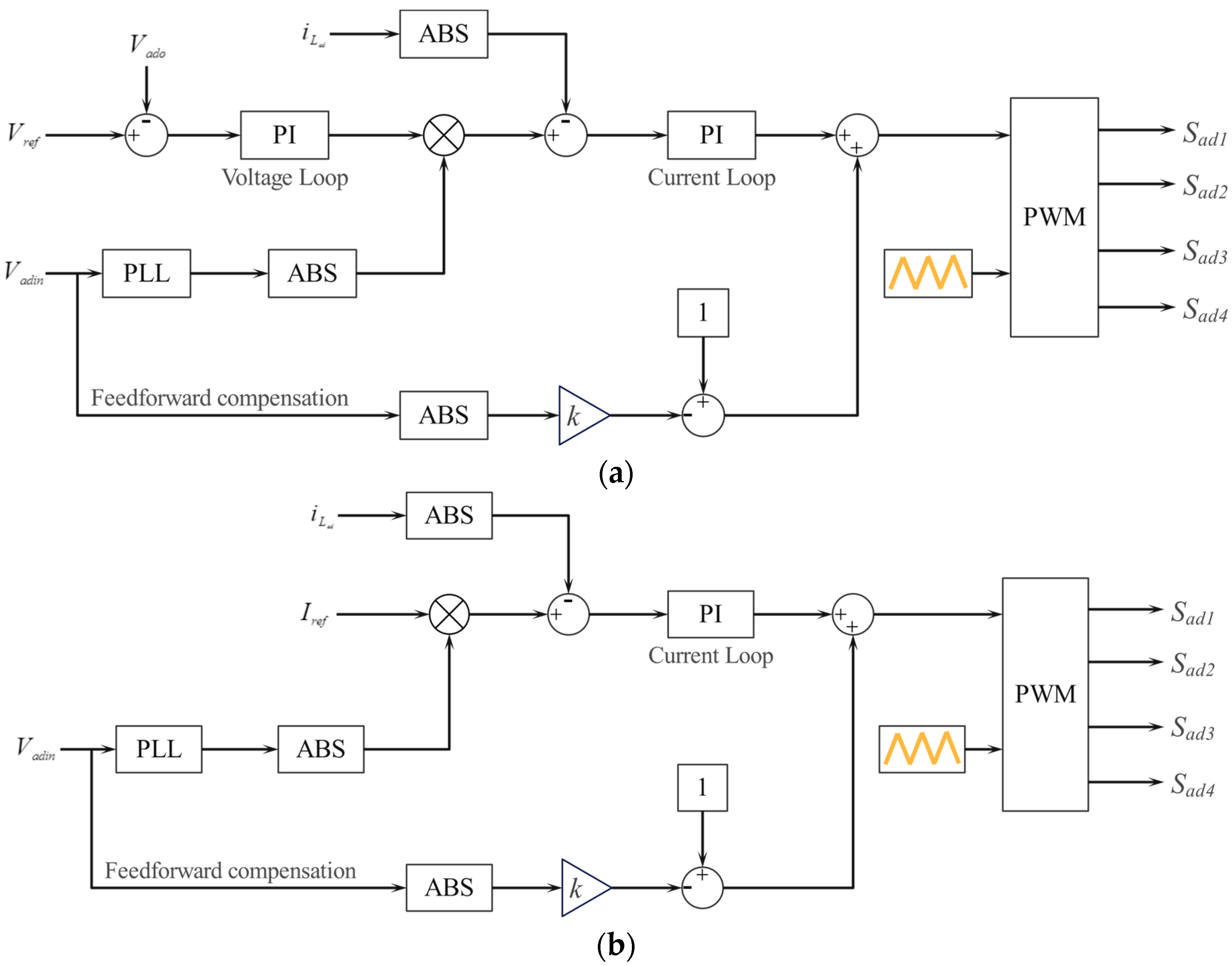
The overall control method of the bidirectional AC/DC converter is a double-closed-loop PI average current control. The controller shown in Figure 6 consists of a voltage change and a current loop. The core of the double-closed-loop PI control is to control the switches through the output duty cycle dr and adjust the amplitude and phase of the inductor current to control the output voltage. First, the output voltage error signal is generated by comparing the output voltage V0 collected by the output voltage sampling circuit with the reference voltage Vref. Then, the voltage error signal is multiplied by the input voltage to generate the reference current signal. The reference current signal thus has both the amplitude and phase information of the input voltage as well as the output voltage information. The inductor current iLad collected by the current sampling circuit is compared with the reference current signal, and finally, the gate signals of the four switches are generated by the current loop PI controller.
For this topology shown in Figure 7, the block diagram of the double-closed-loop PI forward and inverse transform control algorithm is shown below.
In terms of the double-closed-loop PI forward transform control algorithm shown in Figure 7, the input values are the voltage of the AC port Vadin, the voltage of the DC port Vado, the reference voltage of the DC port Vref, and the current of the inductor iLad. On the other hand, in the double-closed-loop PI inverse transform control algorithm, the input values are the voltage of the AC port Vadin, the reference current of the inductor Iref, and the current of the inductor iLad.

3.2. PPP-Based TAB Converter

To derive the energy flow expression of a PPP-based TAB converter, the characteristics of power transmission of two ports in an isolated TAB converter are first analyzed. The phase-shift PWM method is applied to control the power flow direction in the proposed converter. According to [29], the equation of power transmission between any two ports in an isolated TAB converter can be obtained as shown in Equation (4). Taking the control signals of switches S1 and S2 as references, the control signals of switches S7 and S8 and switches S11 and S12 are lagged by φ2 and φ3 radians, respectively, as exhibited in Figure 8. It is essential to consider that −π < φ2 < π, −π < φ3 < π. Moreover, each switch operates with a duty ratio equal to half of the switching cycle. Furthermore, the current waveforms of Ldc1, Ldc2, and Ldc3 in a conventional isolated TAB converter are displayed in Figure 8, representing iL1, iL2, and iL3, respectively. For simplicity in analysis, the turns ratio N1:N2:N3 of the transformer is set at 1:1:1.
P d c 12 = V 1 I 1 = φ 2 ( π φ 2 ) V 1 V 2 2 π 2 f d c s ( L d c 1 + L d c 2 ) P d c 13 = V 3 I 3 = φ 3 ( π φ 3 ) V 1 V 3 2 π 2 f d c s ( L d c 1 + L d c 3 ) P d c 23 = V 2 I 2 = ( φ 3 φ 2 ) ( π φ 3 φ 2 ) V 1 V 2 2 π 2 f d c s ( L d c 2 + L d c 3 )
In Equation (4), VTAB1, VTAB2, and VTAB3 correspond to the voltages at port 1, port 2, and port 3, respectively. Pdc12, Pdc13, and Pdc23 denote the power flow from port 1 to port 2, from port 1 to port 3, and from port 2 to port 3, respectively. Additionally, fdcs represents the switching frequency of gate signals. When considering the proposed PPP-based TAB converter, due to the direct transfer of unprocessed energy through inductors, the conducted energy within a single operational cycle can be calculated using Equation (5), where Cdc12, Cdc13, and Cdc23 represent the conducted power flow from port 1 to port 2, from port 1 to port 3, and from port 2 to port 3, respectively.
C d c 12 = ( V 1 V 2 ) ( L d c 1 + L d c 2 ) f d c s C d c 13 = ( V 1 V 3 ) ( L d c 1 + L d c 3 ) f d c s C d c 23 = ( V 2 V 3 ) ( L d c 2 + L d c 3 ) f d c s
Subsequently, the overall power exchanged among these three ports can be computed by combining the processed power and the conducted power from Equations (4) and (5). The expression for the total power transferred among the different ports is given in Equation (6), where Tdc12, Tdc13, and Tdc23 represent the total power flow from port 1 to port 2, from port 1 to port 3, and from port 2 to port 3, respectively.
T d c 12 = φ 2 π φ 2 V 1 V 2 + 2 π 2 ( V 1 V 2 ) 2 π 2 f d c s ( L d c 1 + L d c 2 ) T d c 13 = φ 3 ( π φ 3 ) V 1 V 3 + 2 π 2 ( V 1 V 3 ) 2 π 2 f d c s ( L d c 1 + L d c 3 ) T d c 23 = ( φ 3 φ 2 ) ( π φ 3 φ 2 ) V 1 V 2 + 2 π 2 ( V 2 V 3 ) 2 π 2 f d c s ( L d c 2 + L d c 3 )
Assuming that each inductor possesses an identical inductance, and the sum of any pair of inductors is denoted as Lddc, the port power can be obtained using the following equation:
T d c 1 = T d c 12 + T d c 13 = φ 2 π φ 2 V 1 V 2 + φ 3 π φ 3 V 1 V 3 + 4 π 2 V 1 2 π 2 ( V 2 + V 3 ) 2 π 2 f d c s L d d c T d c 2 = T d c 12 + T d c 23 = φ 2 π φ 2 V 1 V 2 + ( φ 3 φ 2 ) π φ 3 φ 2 V 2 V 3 + 4 π 2 V 2 2 π 2 ( V 1 + V 3 ) 2 π 2 f d c s L d d c T d c 3 = T d c 13 T d c 23 = φ 3 π φ 3 V 1 V 3 ( φ 3 φ 2 ) π φ 3 φ 2 V 2 V 3 + 4 π 2 V 3 2 π 2 ( V 1 + V 2 ) 2 π 2 f d c s L d d c  
where Tdc1, Tdc2, and Tdc3 represent the total power of port 1, port 2, and port 3, respectively.
It is evident that the energy flow at each port is solely influenced by the phase shift angles, as long as the port voltages remain constant. Consequently, the power transmission direction is contingent on both the phase shift angles and the voltage levels of the ports. For instance, Figure 9 displays four typical energy flow scenarios. For example, when Tdc1 > 0, Tdc2 < 0, and Tdc3 < 0 which also means 0 < φ2 < φ3, as depicted in Figure 8, the combined power flow from port 1 to port 2 and port 3 is evident. Consequently, the capacity for multi-directional power flow can be achieved by modulating the phase shift angles of the converter switches within a specific range of variation in the port voltages.

3.3. Power Efficiency Analysis

Pin is the total input power which can be obtained through pulsing the total output power Pout, semiconductor loss Ps, transformer loss Ptl, and heat loss on passive components Ph shown in (8).
P i n = P o u t + P s + P t l + P h
In semiconductor components, there are typically two types of losses: conduction loss and switching loss. Additionally, the losses incurred by transformers consist of iron and copper losses. In the context of the proposed bidirectional AC/DC converter, the Buck/Boost circuit design, characterized by its simplicity, ensures that conduction and switching losses during the conversion process are minimized. In the case of the proposed PPP-based TAB converter, only a portion of the power is transferred through the transformer, resulting in lower transformer losses which means that the Ptl of a PPP-based TAB converter is less than that of a traditional TAB converter. However, the conduction loss in the proposed converter is relatively higher due to the presence of power cables. By eliminating conduction losses through the use of low-resistance cables with a short distance, which means that the Ps of a PPP-based TAB converter is less than that of a traditional TAB converter, the overall losses in the proposed converter can be reduced, thus achieving greater power efficiency compared to the conventional TAB converter. In summary, this design of an MER has less loss during the conversion process than that of others in [30,31,32,33].

4. Simulation Results

To assess the viability of the proposed power transmission method, a MATLAB/Simulink simulation model is developed, featuring three battery packs. The designed models are depicted in Figure 1. The system configurations are exhibited in Table 1, where the voltages of the AC port and DC port of the bidirectional AC/DC converter are 311 V and 400 V. The reference voltage and reference current of the bidirectional AC/DC converter model are 400 V and 30 2 A. The voltages of port 1, port 2, and port 3 of the PPP-based TAB converter are set to 400 V, 410 V, and 420 V, respectively. The initial state of charge of the battery pack at port 2 is considered at 50%. The inductance of L1, L2, and L3 are all 300 μH, and the capacitance of C1 and C2 are both 100 μF. Moreover, the converter switching frequency is 10 kHz and the transformer turns ratio is 1:1:1. In this section, there are five simulations that test the two kinds of power transmission direction of the bidirectional AC/DC converter and four power flows of the PPP-based TAB converter.

4.1. AC/DC Conversion of Bidirectional AC/DC Converter

According to the analysis of the relationship of φ2 and φ3 of the PPP-based TAB converter, when φ2 and φ3 satisfy the relationship in Figure 9a,b, the bidirectional AC/DC converter is in rectifier mode. This means the AC power is transferred into the DC power in the system.
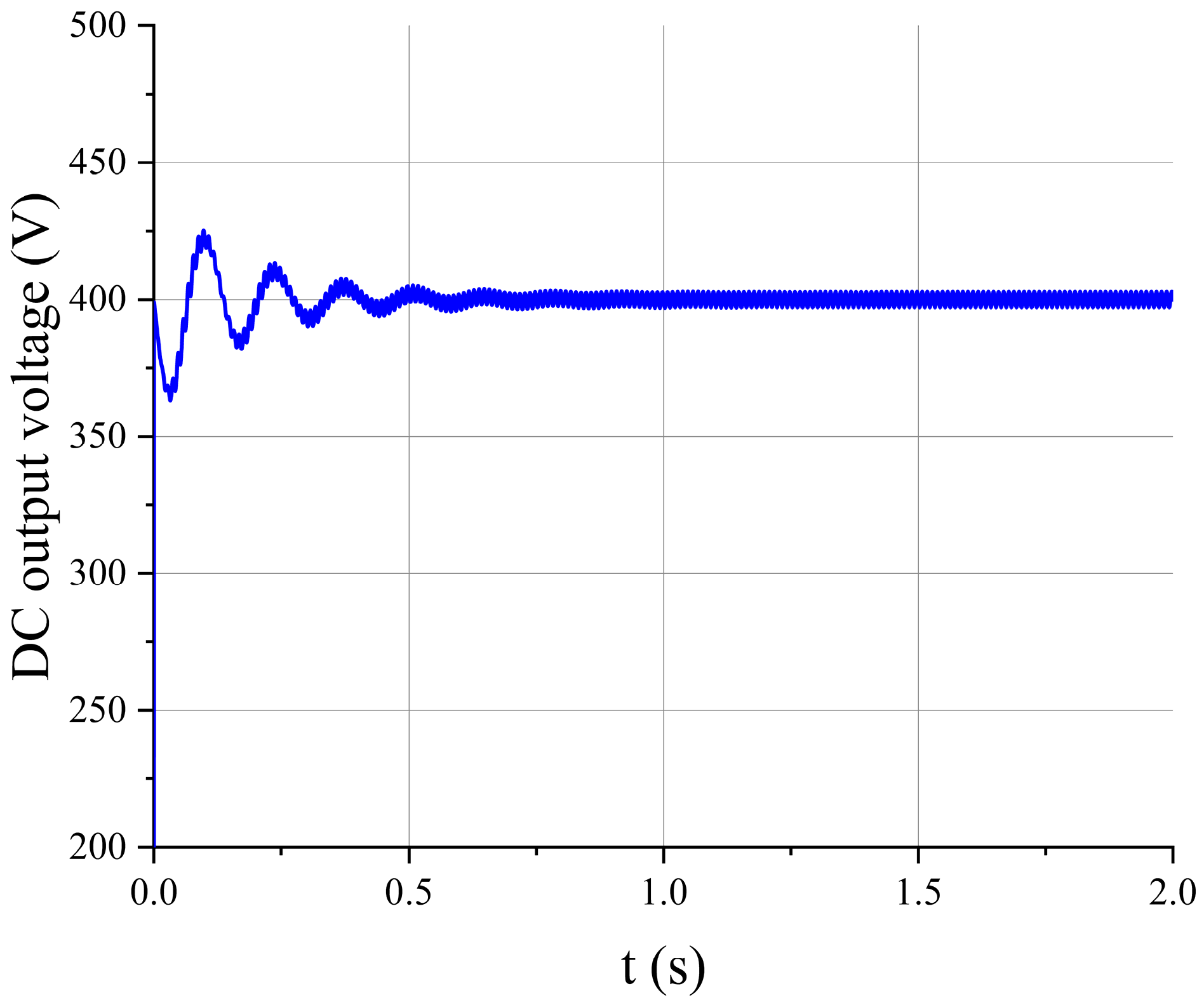
Figure 10 shows the output voltage of the DC port. It is obvious that during the steady state, the voltage can be maintained at 400 V. Moreover, there is a negligible fluctuation in the voltage at the steady state condition. This shows that the proposed bidirectional AC/DC converter can provide a stable and continuous DC voltage to port 1 of the PPP-based TAB converter by transferring the AC power into DC power.
Figure 11 shows the active power, reactive power, and power factor of the bidirectional ACDC converter at the AC port. During the steady state, these two values are mainly at about 0 W and 6500 W, respectively. This means that the power factor of the bidirectional AC/DC converter is nearly one when transferring the AC power to the DC power.

4.2. DC/AC Conversion of Bidirectional AC/DC Converter

When φ2 and φ3 satisfy the relationship in Figure 9c, the bidirectional AC/DC converter is in inverter mode which means that it transfers DC power into AC power.
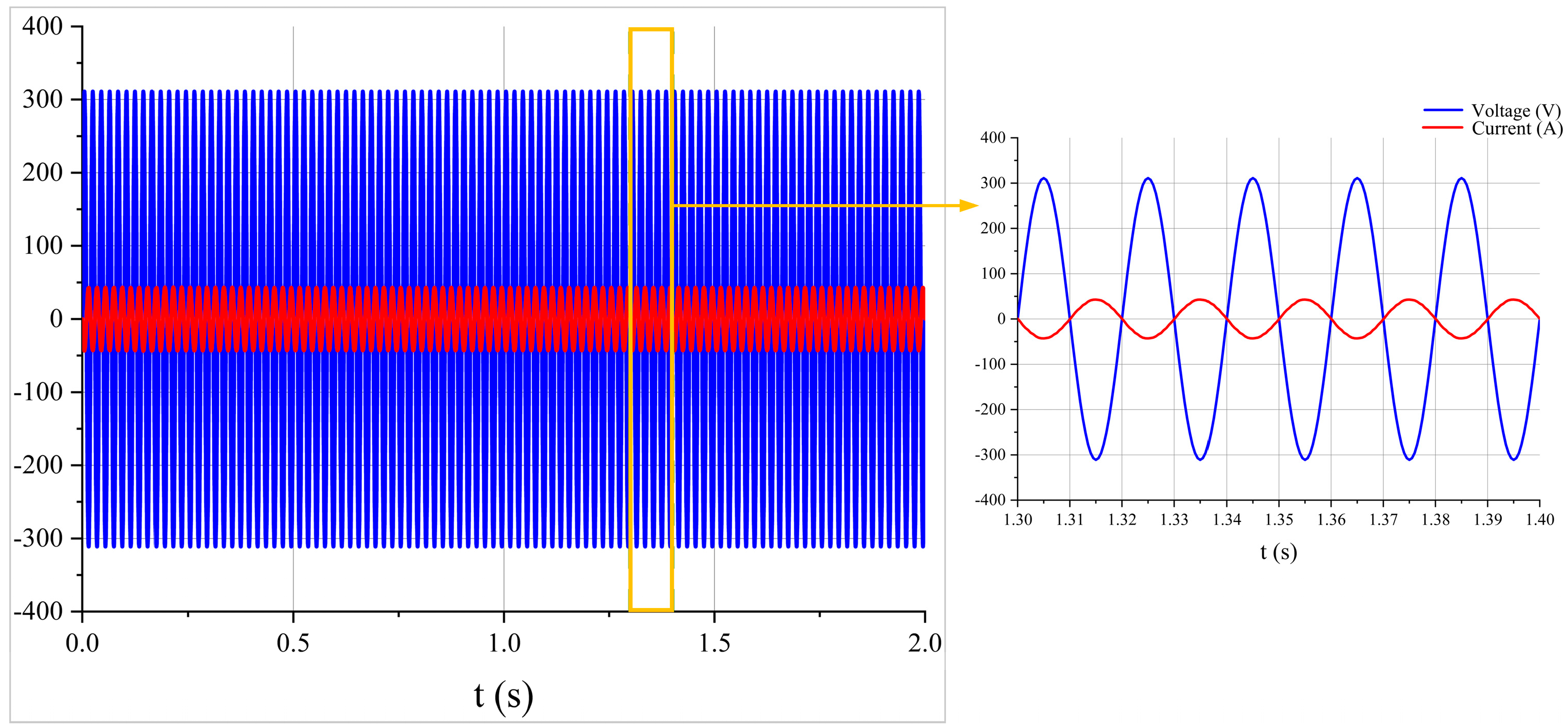
Figure 12 shows the output voltage and current of the AC port during the steady state. It is obvious that during the steady state, the voltage and current waveform still conform to the design requirement of the bidirectional AC/DC converter. This means that the PPP-based TAB converter can provide a stable and continuous AC voltage to the AC port of the bidirectional AC/DC converter by transferring the DC power into AC power.
Figure 13 shows the power factor of the bidirectional AC/DC converter at the AC port. During the steady state, these three values are mainly at about −1. This means that the efficiency of the bidirectional AC/DC converter is also high when transferring the DC power to the AC power.

4.3. DC/DC Conversion of PPP-Based TAB Converter

To ensure the working status of the PPP-based TAB converter in four different kinds of power direction flows shown in Figure 9, the results below are shown in different situations of ports 2 and 3.

4.3.1. When Port 2 and 3 Are Output Ports

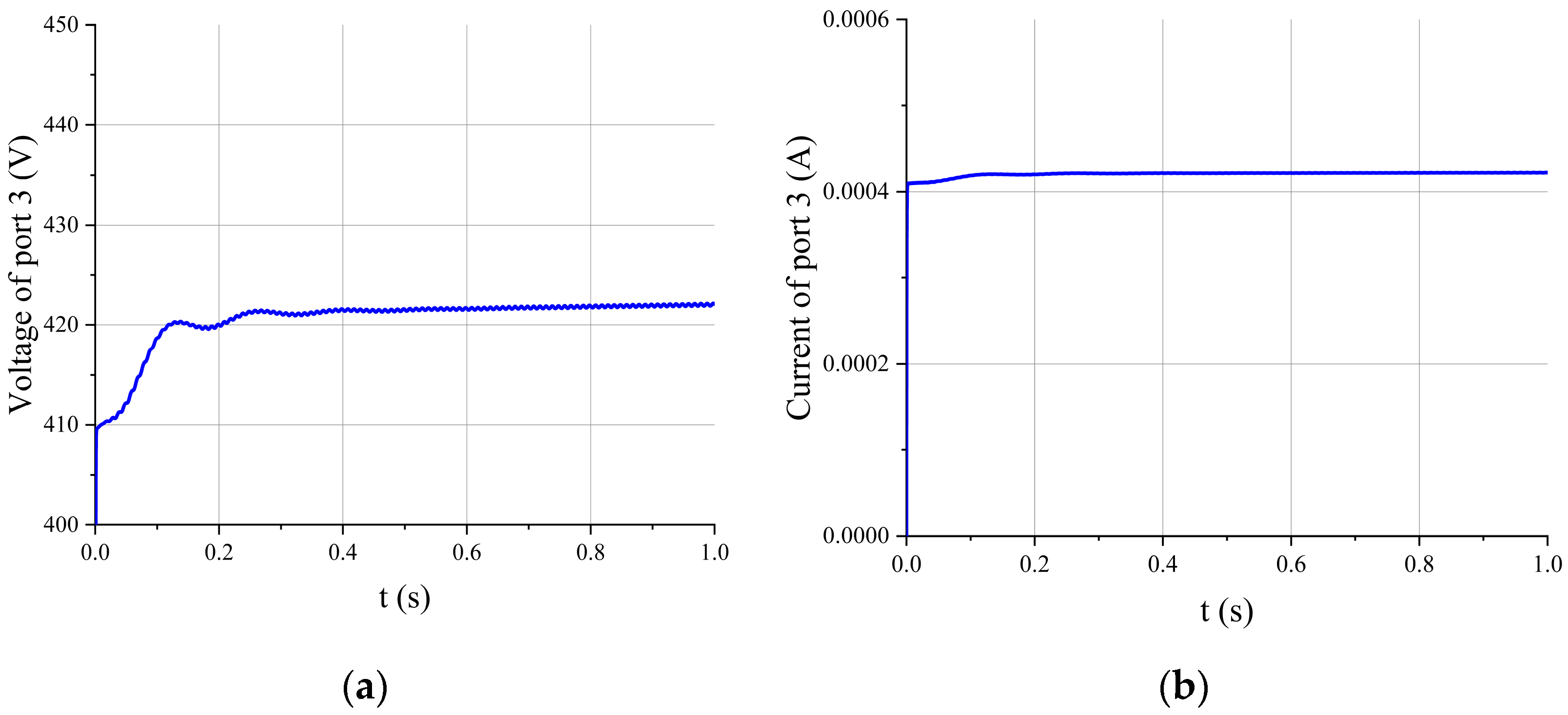
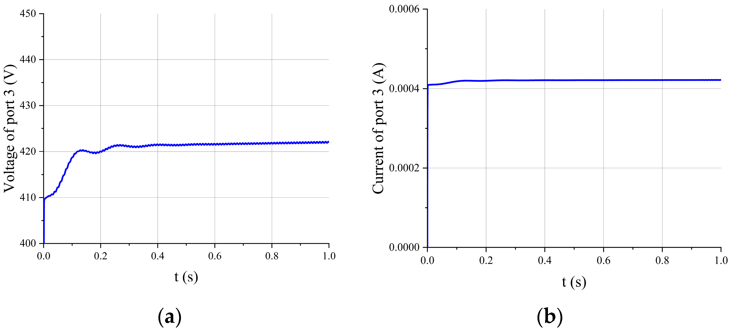
In this situation, it means that the power grid has enough energy to satisfy the needs of all the loads and the charging of EPPSs and ERSUs. The direction of power transmission is shown in Figure 9a. Figure 14 shows the voltage and current of port 3 when ports 2 and 3 are output ports. The voltage and current of port 3 are all positive and it is obvious that the voltage of port 3 can be maintained at about 420 V in steady states which means that the loads can be supplied by a PPP-based TAB converter and an MER continuously and steadily. In addition, because the current of port 3 is positive, as shown in Figure 14b, port 3 is the output port of the PPP-based TAB converter.
Table 2 is the SOC of an EPPS at port 2. The EPPS at port 2 can be charged stable and port 2 is the output port in this condition. This means that in this relationship between φ2 and φ3, port 1 is the input port, and ports 2 and 3 are the output ports which corresponds to the conclusion obtained in Figure 9a.

4.3.2. When Port 2 Is Input Port and Port 3 Is Output Port

In this situation, it means that the power grid does not have enough energy or the power grid is paralyzed. Port 2 needs to become the input port to supply power to the loads at port 3 to ensure the normal working of all the loads. The direction of power transmission is shown in Figure 9b,d when port 2 is the input port and port 3 is the output port. Figure 15 shows the voltage and current of port 3 when port 2 is the input port. The voltage and current of port 3 are all positive and it is obvious that the voltage of port 3 can be maintained at about 420 V in steady states which means that the loads can be supplied by a PPP-based TAB converter and an MER continuously and steadily.
Table 3 is the SOC of an EPPS at port 2. The EPPS at port 2 can be discharged stable and port 2 is the input port in this condition. This means that in these relationships, between φ2 and φ3, port 2 is the input port and port 3 is the output port which corresponds to the conclusion obtained in Figure 9b,d.

4.3.3. When Port 1 and 3 Are Output Ports

In this situation, it means that the EPPS has extra energy to supply to the power grid so that P2P can be realized. The direction of power transmission is shown in Figure 9c. Figure 16 shows the voltage of port 3 when ports 1 and 3 are output ports. The voltage and current of port 3 are all positive and it is obvious that the voltage of port 3 can be maintained at about 420 V in steady states which means that the loads can be supplied by a PPP-based TAB converter and an MER continuously and steadily. In addition, because the current of port 3 is positive, as shown in Figure 16b, port 3 is the output port of the PPP-based TAB converter.
Table 4 shows the SOC of an EPPS at port 2. The EPPS at port 2 can be discharged stable and port 2 is the input port in this condition. This means that in this relationship, between φ2 and φ3, port 2 is the input port, and ports 1 and 3 are the output ports which corresponds to the conclusion obtained in Figure 9c.

5. Experimental Verification

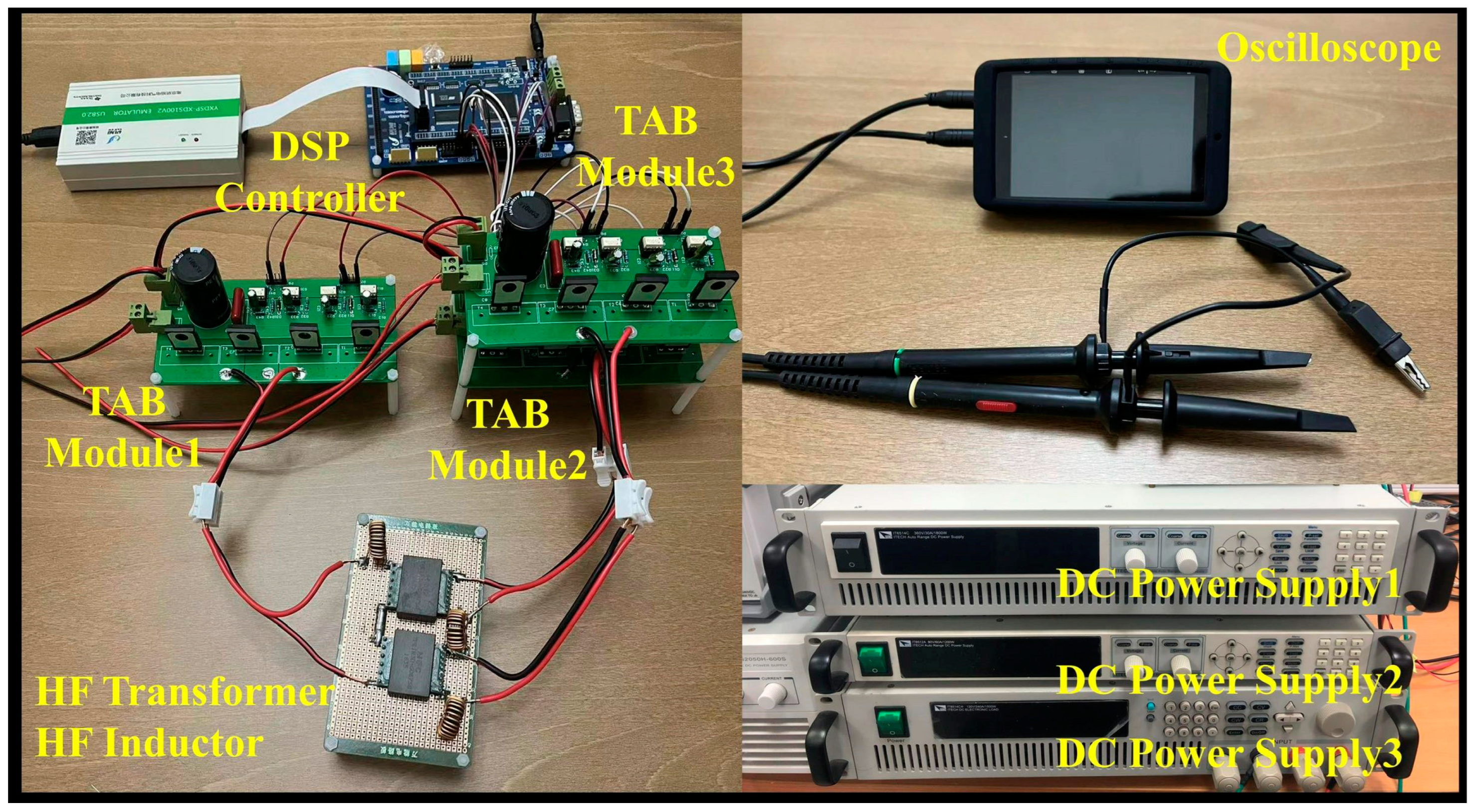
To verify the inputs and outputs of each port of the TAB converter for different relationships of φ2 and φ3, an experimental circuit is set up as shown in Figure 17. The parameters of the experiment are shown in Table 5. To ensure the safety of the experiment, a lower port voltage is used in the experiment. However, the conclusion of the power transmission direction of each port with the relationship of φ2 and φ3 is not affected because according to Equation (7), the power direction of the PPP-based TAB converter is only affected by the relationship of φ2 and φ3 and the voltage difference between port voltages. Hence, a lower port voltage will not influence the conclusion of power transmission direction based on the relationship of φ2 and φ3 since the voltage differences of port voltages are still very small. In addition, the instance Lx is 33 μH and N1:N2:N3 = 10:8:8. Although the instance and transformer turns ratio are also different from the simulation model, the power transmission direction of the PPP-based TAB converter will not be affected by them according to Equation (7).
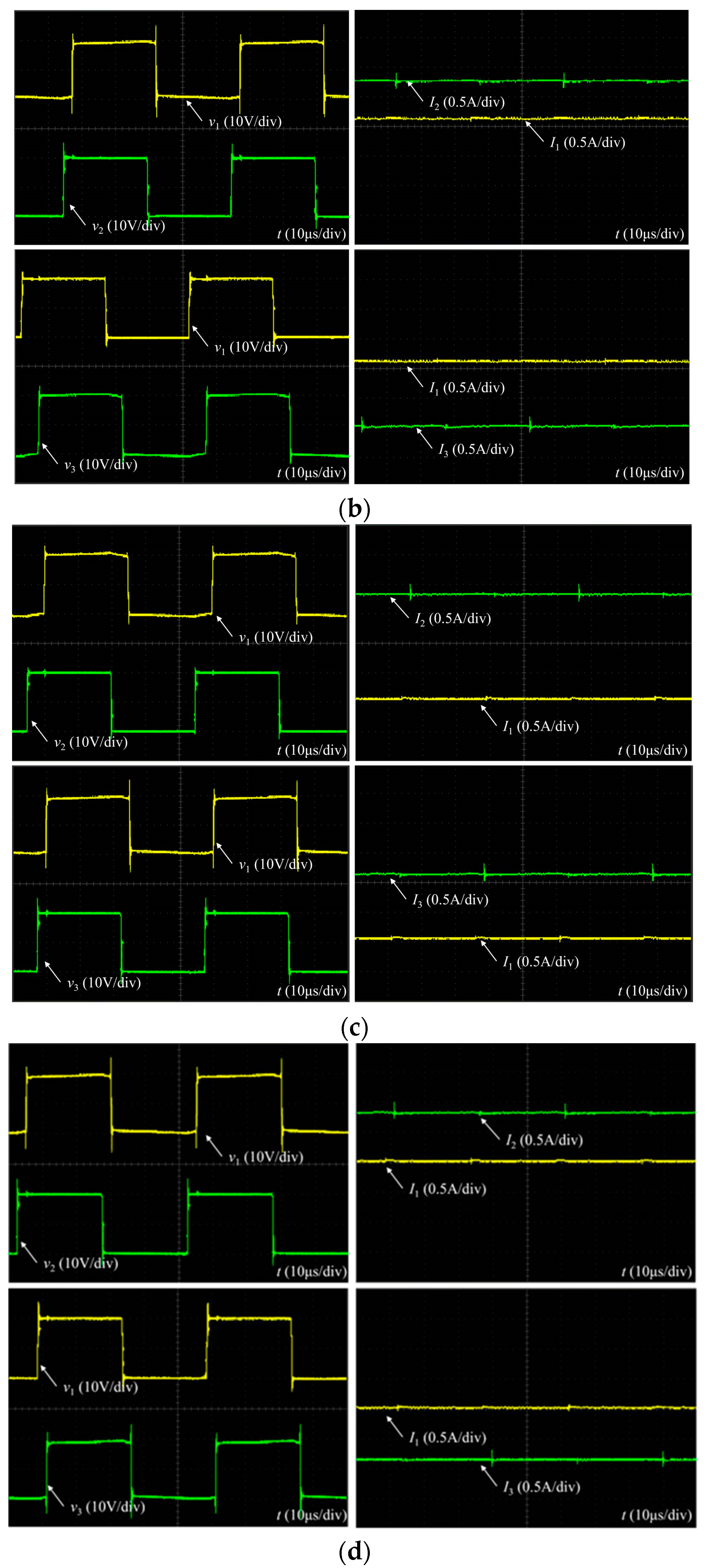
Figure 18 shows the four different power flow directions. The left side of each figure shows the switch voltage of each port which shows the relationship of φ2 and φ3 and the right side of each figure shows the current of each port which shows the power flow direction. On the right side of each figure, the horizontal reference line means 0 A current. Above the horizontal reference line, it means the port current is positive and the port is the output. On the opposite side, being below the horizontal reference line means the port current is negative and the port is the input. From Figure 18, the relationship between power flow direction and φ2 and φ3 is consistent with the theory shown in Figure 9 and the simulation.

6. Conclusions

This paper presents a multi-port energy router that is designed to deal with emergency power outages and realize the energy balancing between different power sources and loads. The more ports the MER has, the more types of EEPSs and loads can be managed and energized at the same time. In addition, more flexible urban energy management for emergency power needs is realized by mounting the MER on mobile energy storage. An AC/DC power conversion is accomplished by a bidirectional AC/DC converter, and DC/DC power transmission is realized utilizing a PPP-based TAB converter. To realize P2P trading and energy balancing, both ports in the bidirectional AC/DC converter and PPP-based TAB converter can be input ports or output ports according to different situations and working requirements. In addition, because the MER is multi-port, two customers can also exchange energy with each other through two ports so that the customer’s dependence on the main grid can be reduced and the distribution of power can be rationalized according to their needs. Compared to a conventional emergency distribution way and an existing ER, the designed MER has a higher power conversion efficiency and various EEPSs. For now, the designed MER has only three ports. However, the ports of MER can be increased by increasing the ports of the DC/DC converter so that more EEPSs can be utilized in the MER at the same time so that clients can enjoy a wider variety of energy supply options to cope with unpredictable power outages with high power efficiency and utilization. In the future, by increasing the ports of MER or combining multiple numbers of MERs to form an emergency electric power system, the problems of emergency power outages can be solved completely. A simulation model is tested in MATLAB/Simulink so that the feasibility of the proposed ER can be verified. In addition, each working situation of the bidirectional AC/DC converter and PPP-based TAB converter has been tested which proves that the proposed ER is highly efficient and makes it easy to change the working states to deal with different situations.

Author Contributions

Methodology, Y.N.; Validation, Y.N. and X.L.; Formal analysis, Y.H.; Investigation, M.N.E. and M.A.; Resources, M.A.; Data curation, Y.N.; Writing—original draft, Y.N.; Writing—review & editing, M.N.E., Y.H., X.L. and M.A.; Supervision, M.N.E. and Y.H. All authors have read and agreed to the published version of the manuscript.

Funding

This project was supported by the Natural Science Foundation of Shandong Province, China under Grant (ZR2021ME236). The authors extend their appreciation to the Deanship of Graduate Studies and Scientific Research at University of Bisha for funding this research through the promising program under grant number (UB-Promising-38-1445).

Data Availability Statement

The original contributions presented in the study are included in the article, further inquiries can be directed to the corresponding author.

Acknowledgments

The authors extend their appreciation to the Deanship of Scientific Research at the University of Bisha, Saudi Arabia, for funding this research work through the Promising Program under grant number (UB-Promising-38-1445).

Conflicts of Interest

The authors declare no conflict of interest.

Abbreviations

MERMulti-port energy router
EREnergy router
EEPSEmergency electric power source
PPPPartial power processing
TABTriple active bridge
DABDual active bridge
SOCState of charge
P2PPeer-to-peer
EVElectric vehicle
PWMPulse-width modulation
CCMContinuous conduction mode
ERSUEnergy router storage unit
PLLPhase-locked loop
PDPhase angle detector
LFLoop filter
VCOVoltage-controlled oscillator
SOGISecond-order generalized integrator
FPGFrequency/phase angle generator
QSGQuadrature signal generator
ADAdaptive filter

References

  1. Zhou, B.; Gu, L.; Ding, Y.; Shao, L.; Wu, Z.; Yang, X.; Li, C.; Li, Z.; Wang, X.; Cao, Y.; et al. The Great 2008 Chinese Ice Storm: Its Socioeconomic–Ecological Impact and Sustainability Lessons Learned. Bull. Am. Meteorol. Soc. 2011, 92, 47–60. [Google Scholar] [CrossRef]
  2. Byrd, H.; Matthewman, S. Exergy and the City: The Technology and Sociology of Power (Failure). J. Urban Technol. 2014, 21, 85–102. [Google Scholar] [CrossRef]
  3. Buragohain, B.; Mahanta, P.; Moholkar, V. Biomass gasification for decentralized power generation: The Indian perspective. Renew. Sustain. Energy Rev. 2010, 14, 73–92. [Google Scholar] [CrossRef]
  4. Graham, S.; Thrift, N. Out of Order. Theory Cult. Soc. 2007, 24, 1–25. [Google Scholar] [CrossRef]
  5. Nie, Y.; Xu, H.; Hu, Y.; Ye, X. Energy Router for Emergency Energy Supply in Urban Cities: A Review. Power Electron. Drives 2022, 7, 246–266. [Google Scholar] [CrossRef]
  6. Bhattacharyya, S.; Myrzik, J.M.A.; Kling, W.L. Consequences of poor power quality-an overview. In Proceedings of the 2007 42nd International Universities Power Engineering Conference, Brighton, UK, 4–6 September 2007. [Google Scholar]
  7. Nye, D.E. When the Lights Went Out; MIT Press: Cambridge, MA, USA, 2010; Volume 8, pp. 103405–103418. [Google Scholar]
  8. Halperin, D.; Heydt-Benjamin, T.S.; Ransford, B.; Clark, S.S.; Defend, B.; Morgan, W.; Fu, K.; Kohno, T.; Maisel, W.H. Pacemakers and implantable cardiac defibrillators: Software radio attacks and zero-power defenses. In Proceedings of the 2008 IEEE Symposium on Security and Privacy, Oakland, CA, USA, 18–21 May 2008. [Google Scholar]
  9. Yue, W.; Zhao, C.; Lu, Y.; Li, G. A scheme of connecting microgird to AC grid via flexible power electronics interface. In Proceedings of the 2010 International Conference on Power System Technology, Hangzhou, China, 24–28 October 2010. [Google Scholar]
  10. Zhao, Y.; Li, C.; Zhao, M.; Xu, S.; Gao, H.; Song, L. Model design on emergency power supply of electric vehicle. Math. Probl. Eng. 2017, 2017, 9697051. [Google Scholar] [CrossRef]
  11. Bulatov, Y.; Kryukov, A.; Suslov, K. Isolated Power Supply System with Energy Routers and Renewable Energy Sources. Vestnik IzhGTU imeni M.T. Kalashnikova 2021, 23, 124. [Google Scholar] [CrossRef]
  12. Xu, Y.; Zhang, J.; Wang, W.; Juneja, A.; Bhattacharya, S. Energy router: Architectures and functionalities toward Energy Internet. In Proceedings of the 2011 IEEE International Conference on Smart Grid Communications (SmartGridComm), Brussels, Belgium, 17–20 October 2011. [Google Scholar]
  13. Ahmad, J.; Tahir, M.; Mazumder, S.K. Improved Dynamic Performance and Hierarchical Energy Management of Microgrids With Energy Routing. IEEE Trans. Ind. Inform. 2019, 15, 3218–3229. [Google Scholar] [CrossRef]
  14. Yang, R.; Liu, Z.; Liu, J. The methodology of decoupling fuel and thermal nitrogen oxides in multi-dimensional computational fluid dynamics combustion simulation of ammonia-hydrogen spark ignition engines. Int. J. Hydrogen Energy 2024, 55, 300–318. [Google Scholar] [CrossRef]
  15. Liu, J.; Liu, Z. In-cylinder thermochemical fuel reforming for high efficiency in ammonia spark-ignited engines through hydrogen generation from fuel-rich operations. Int. J. Hydrogen Energy 2024, 54, 837–848. [Google Scholar] [CrossRef]
  16. Ansari, S.; Chandel, A.; Tariq, M. A Comprehensive Review on Power Converters Control and Control Strategies of AC/DC Microgrid. IEEE Access 2021, 9, 17998–18015. [Google Scholar] [CrossRef]
  17. Abdella, J.; Shuaib, K. Peer to peer distributed energy trading in smart grids: A survey. Energies 2018, 11, 1560. [Google Scholar] [CrossRef]
  18. Hosseini, S.S.; Badri, A.; Parvania, M. A survey on mobile energy storage systems (MESS): Applications, challenges and solutions. Renew. Sustain. Energy Rev. 2014, 40, 161–170. [Google Scholar] [CrossRef]
  19. Bie, Z.; Lin, Y.; Li, G.; Li, F. Battling the Extreme: A Study on the Power System Resilience. Proc. IEEE 2017, 105, 1253–1266. [Google Scholar] [CrossRef]
  20. Nadeem, F.; Hussain, S.M.S.; Tiwari, P.K.; Goswami, A.K.; Ustun, T.S. Comparative Review of Energy Storage Systems, Their Roles, and Impacts on Future Power Systems. IEEE Access 2019, 7, 4555–4585. [Google Scholar] [CrossRef]
  21. Seal, S.; Boulet, B.; Dehkordi, V.R.; Bouffard, F.; Joos, G. Centralized MPC for Home Energy Management With EV as Mobile Energy Storage Unit. IEEE Trans. Sustain. Energy 2023, 14, 1425–1435. [Google Scholar] [CrossRef]
  22. Zientarski, J.R.R.; Martins, M.L.D.S.; Pinheiro, J.R.; Hey, H.L. Evaluation of Power Processing in Series-Connected Partial-Power Converters. IEEE J. Emerg. Sel. Top. Power Electron. 2019, 7, 343–352. [Google Scholar] [CrossRef]
  23. Anzola, J.; Aizpuru, I.; Romero, A.A.; Loiti, A.A.; Lopez-Erauskin, R.; Bernal, C. Review of Architectures Based on Partial Power Processing for DC-DC Applications. IEEE Access 2020, 8, 103405–103418. [Google Scholar] [CrossRef]
  24. Qi, J.; Lu, D.D.-C. A flyback converter based partial power processing structure for BESS with voltage/current regulation and battery balancing functionalities. In Proceedings of the 2017 IEEE International Telecommunications Energy Conference (INTELEC), Broadbeach, QLD, Australia, 22–26 October 2017. [Google Scholar]
  25. Mishra, S.; Tamballa, S.; Pallantala, M.; Raju, S.; Mohan, N. Cascaded Dual-Active. In Proceedings of the 20th Workshop on Control and Modeling for Power Electronics (COMPEL), Toronto, ON, USA, 17–20 June 2019. [Google Scholar]
  26. Honarmand, S.; Rajaei, A.; Shahparasti, M.; Luna, A.; Pouresmaeil, E. A modified partial power structure for quasi Z-source converter to improve voltage gain and power rating. Energies 2019, 12, 2139. [Google Scholar] [CrossRef]
  27. Liu, Y.; Hu, Y.; Chen, G.; Wen, H. Partial Power Processing Multiport DC–DC Converter With Radial Module Connections. IEEE Trans. Power Electron. 2022, 37, 13398–13412. [Google Scholar] [CrossRef]
  28. Uno, M.; Sato, M.; Tada, Y.; Iyasu, S.; Kobayashi, N.; Hayashi, Y. Partially Isolated Multiport Converter With Automatic Current Balancing Interleaved PWM Converter and Improved Transformer Utilization for EV Batteries. IEEE Trans. Transp. Electrif. 2023, 9, 1273–1288. [Google Scholar] [CrossRef]
  29. Nie, Y.; Zhang, Y.; Hu, Y. Integrated Power/Signal Transmission in Triple Active Bridge Converters Based on Partial Power Processing for Energy Routers. In Proceedings of the 2022 IEEE Transportation Electrification Conference and Expo, Asia-Pacific (ITEC Asia-Pacific), Haining, China, 17–20 June 2022. [Google Scholar]
  30. Liu, B.; Peng, Y.; Xu, J.; Mao, C.; Wang, D.; Duan, Q. Design and Implementation of Multiport Energy Routers Toward Future Energy Internet. IEEE Trans. Ind. Appl. 2021, 57, 1945–1957. [Google Scholar] [CrossRef]
  31. Kai, Y.; Wang, Y.; Liu, B. GreenRouter: Reducing Power by Innovating Router’s Architecture. IEEE Comput. Archit. Lett. 2013, 12, 51–54. [Google Scholar] [CrossRef]
  32. Karbozov, A.; Majumder, M.G.; Krishnamoorthy, H.S.; Rajashekara, K. Triple Active Bridge Based Multiport Energy Router for Subsea–Renewable Interconnection. IEEE Trans. Ind. Appl. 2023, 59, 4528–4538. [Google Scholar] [CrossRef]
  33. Chen, Y.; Wang, P.; Elasser, Y.; Chen, M. Multicell Reconfigurable Multi-Input Multi-Output Energy Router Architecture. IEEE Trans. Power Electron. 2020, 35, 13210–13224. [Google Scholar] [CrossRef]
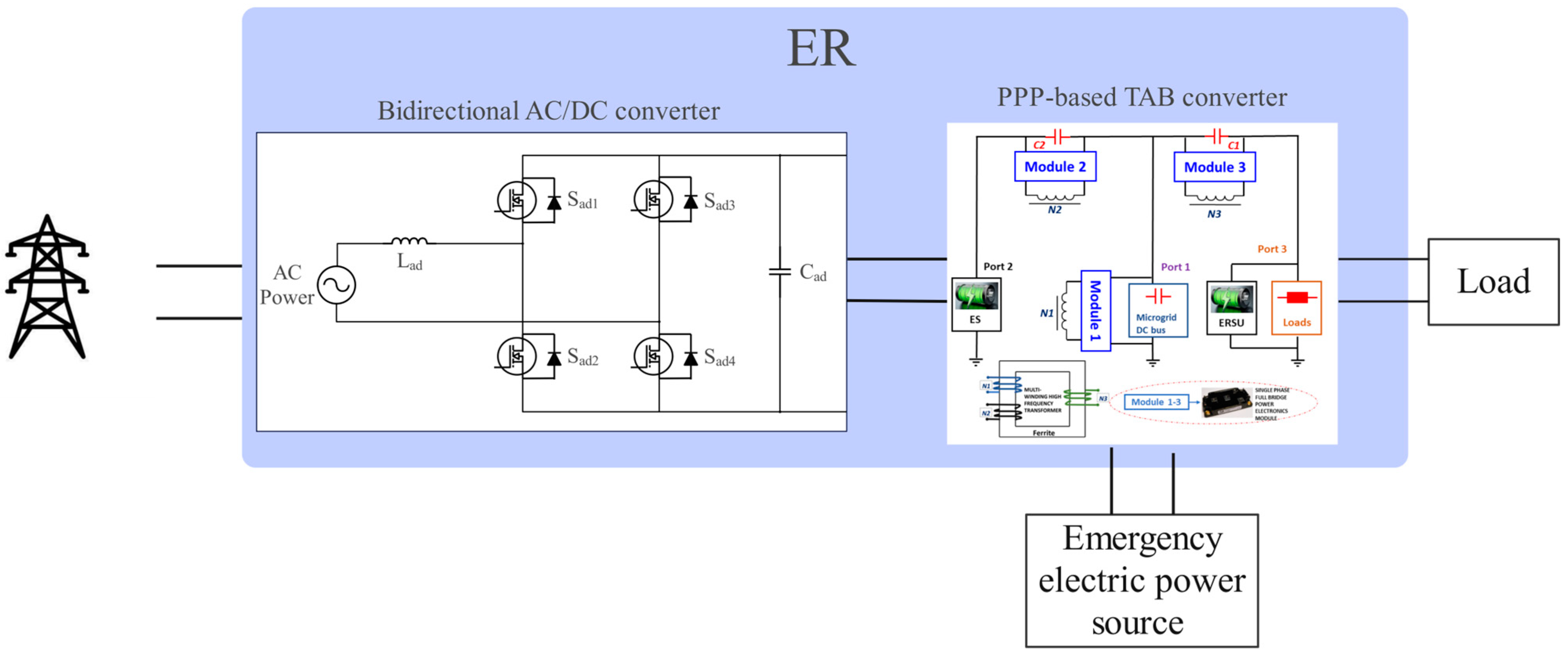
Figure 1. The connection between various power sources, energy routers (ERs) and loads.
Energies 17 02927 g001
Figure 2. Topology of proposed bidirectional AC/DC converter.
Energies 17 02927 g002
Figure 3. The (a) topology and (b) circuit diagrams of the PPP-based TAB converter including three ports, where the power grids, EEPSs, and ERSUs are connected.
Energies 17 02927 g003
Figure 4. Typical waveforms when bidirectional AC/DC converter conducts forward energy transmission.
Energies 17 02927 g004
Figure 5. The structure of SOGI-PLL with a combination of QSG and Park transform in a synchronous PD.
Energies 17 02927 g005
Figure 6. The structure of a basic double-closed-loop PI average control.
Energies 17 02927 g006
Figure 7. Double-closed-loop PI average current control of (a) AC/DC transfer and (b) DC/AC transfer.
Energies 17 02927 g007
Figure 8. The typical waveforms of an isolated TAB converter.
Energies 17 02927 g008
Figure 9. The typical power flow directions of the proposed topology where (a) 0 < φ2 < φ3; (b) φ2 < 0 < φ3 and 2| < 3|; (c) φ2 < φ3 < 0; and (d) φ2 < 0 < φ3 and 2| = |φ3|.
Energies 17 02927 g009
Figure 10. DC output voltage of AC/DC transfer.
Energies 17 02927 g010
Figure 11. Active power and reactive power of AC/DC transfer at AC port.
Energies 17 02927 g011
Figure 12. Output AC voltage and current of DC/AC transfer.
Energies 17 02927 g012
Figure 13. Active power and reactive power of DC/AC transfer at AC port.
Energies 17 02927 g013
Figure 14. Waveforms of port 3 when ports 2 and 3 are output ports: (a) voltage and (b) current.
Energies 17 02927 g014
Figure 15. Waveforms of port 3 when port 2 is input port and port 3 is output port: (a) voltage and (b) current.
Energies 17 02927 g015
Figure 16. Waveforms of port 3 when ports 1 and 3 are output ports: (a) voltage and (b) current.
Energies 17 02927 g016
Figure 17. Photograph of experiment circuit.
Energies 17 02927 g017
Figure 18. Experimental switch voltage and current of each port of TAB converter, where (a) 0 < φ2 < φ3; (b) φ2 < 0 < φ3 and 2| < 3|; (c) φ2 < φ3 < 0; and (d) φ2 < 0 < φ3 and 2| = |φ3|.
Energies 17 02927 g018aEnergies 17 02927 g018b
Table 1. Parameters of energy router simulation model.
Parameter NameParameter Value
V1/V2/V3 (Port voltages)400/410/420 V
Vac (Voltage of the main power grid)311 V
SOC (Initial state of charge)50%
RL (Initial resistance of load)200 Ω
N1:N2:N3 (Transformer turns ratio)1:1:1
fs (Converter switching frequency)10 kHz
fac (AC power frequency)50 Hz
Lad (AC/DC converter inductance)360 μH
L1/L2/L3 (Series inductance)300 μH
Cad (AC/DC converter capacitance)9 mF
C1/C2 (Series capacitance)100 μF
Vref (Reference voltage)400 V
Iref (Reference current)30√2 A
Table 2. SOC of port 2 when ports 2 and 3 are output ports.
Time (s)Value of SOC (%)
040
2041.2
3041.8
4042.4
6043.6
Table 3. SOC of port 2 when port 2 is input port and port 3 is output port.
Time (s)Value of SOC (%)
040
2038.8
3038.2
4037.6
6036.4
Table 4. SOC of port 2 when ports 1 and 3 are output ports.
Time (s)Value of SOC (%)
040
2038.8
3038.2
4037.6
6036.4
Table 5. Parameters of TAB converter experiment.
Parameter NameParameter Value
V1/V2/V3 (Port voltages)10/10/10 V
N1:N2:N3 (Transformer turns ratio)10:8:8
fs (Converter switching frequency)10 kHz
L1/L2/L3 (Series inductance)33 μH
Disclaimer/Publisher’s Note: The statements, opinions and data contained in all publications are solely those of the individual author(s) and contributor(s) and not of MDPI and/or the editor(s). MDPI and/or the editor(s) disclaim responsibility for any injury to people or property resulting from any ideas, methods, instructions or products referred to in the content.