Abstract
The green energy transition calls for various solutions to enhance environmental sustainability. One of these is represented by renewable energy communities, which may help transition from centralized energy production to distributed renewable generation. European countries are actively promoting incentive schemes for energy communities to foster local electricity self-consumption in order to balance demand and renewable generation. In this context, energy storage facilities can be employed to gather the energy production surplus and use it in periods of low generation. In this paper, we focus on the optimal operation of an incentive-based energy community in the presence of energy storage systems. A centralized optimization problem was formulated to optimally operate storage systems at the community level. Starting from this solution, distributed charging/discharging commands were found to optimally operate the single storage units. Moreover, conditions guaranteeing the convenience of using energy storage systems inside the community were derived. Numerical simulations were performed to validate the reported results and to evaluate the potential benefits of energy storage facilities inside renewable energy communities.
1. Introduction
The European community is driving its countries to implement sustainable solutions and comply with the net-zero plan reported in the 2050 agenda [1]. For this purpose, it is of paramount importance to transition to novel energy paradigms like renewable energy communities (RECs), the aim of which is to shift centralized energy production to local renewable generation. Most notably, the main objective of an REC is to provide social, environmental and economic benefits to its members by means of renewable generation devices, energy storage facilities and electric vehicles [2]. The participants in an REC can include organizations, citizens and local businesses that partake in the community on a voluntary and open basis. For these reasons, RECs can contribute to enhanced environmental sustainability by establishing a spontaneous synergy among all members.
Research efforts have produced several contributions concerning the operation of RECs [3,4] and how they can be implemented according to regional, social and political factors [5]. The investigated topics span from community models featuring internal markets [6,7] to those focused on incentive-based schemes [8,9]. In this work, we consider an REC where an incentive is provided on the basis of the virtual self-consumption of the community, like in the Italian framework [10]. This quantity is computed for a given time period, and it amounts to the overall renewable energy shared inside the community [11].
It has been shown that joining an REC can increase local self-consumption. In [12], it was shown that the employment of genetic algorithms for the optimal usage of renewable resources provides a boost to REC performance, while the adoption of multi-objective criteria provides economic and environmental benefits [13]. Moreover, the optimization of community facilities may help to increase the social welfare of the affiliated members [14], while joining an REC is a possible tool for addressing energy poverty [15]. The benefits of energy communities in smart building frameworks were assessed in [16], while economic analyses of the profitability of RECs depending on different variables were proposed in [17]. In [18,19], optimization approaches were used to design the allocation of renewable resources in RECs to reduce investment costs and increase their benefits. The optimal management of community devices can reduce carbon emissions and the interaction between the grid and the community [20], as well as optimize the operating costs [21]. The optimal collaboration of REC members to maximize community social welfare was investigated from a game theory perspective in [22].
1.1. Contribution and Novelty
In this paper, the optimal operation of an REC involving consumers, prosumers, producers and energy storage facilities is considered. Starting from load and generation profiles of each member, we provide a centralized optimization framework for the optimal management of the installed storage devices aimed at minimizing the community’s energy bill.
Despite the presence of other contributions involving energy storage systems in RECs, to the best of the authors’ knowledge, none of them provides methodological tools addressing how community incentives affect optimal community operation. To this end, this work aims to fill the identified research gap via the following contributions:
- Provide analytical conditions that assess to what extent the incentive is worthwhile for the participation of storage facilities in REC operation;
- Introduce a low-complexity linear optimization problem obtained by aggregating REC member profiles at the community level;
- Provide a procedure that allows one to compute the optimal distributed storage management starting from the aggregated one.
The main novelties of this work are related to the introduction of tools focused on addressing the optimal operation of storage facilities in incentive-based energy communities in response to a given incentive. In particular,
- We provide conditions under which the self-consumption incentive will trigger the coordination of storage units within the community;
- The proposed optimization framework streamlines the management of RECs by providing insights into the potential benefits of the presence of energy storage through the solution of a low-complexity optimization problem.
1.2. Paper Organization
The paper is organized as follows: In Section 2, the community model is presented, while the optimal community operation problem and technical results are provided in Section 3. In Section 4, the computation of a distributed solution is discussed, while numerical simulations and related results are reported in Section 5. Finally, some conclusions are drawn in Section 6.
1.3. Notation and Nomenclature
The optimal solution of an optimization problem is represented by superscript, while a generic feasible solution is represented by. Symbols used in this work are summarized in the following table.
| Symbol | Description |
| Set of community entity indexes | |
| Set of community entity indexes involving a storage system | |
| REC operation time interval | |
| t, | Time indexes |
| Last REC operation time index | |
| u | Entity index |
| Energy purchase price | |
| Energy selling price | |
| k | Self-consumption unitary incentive |
| Threshold value for the unitary incentive | |
| Energy demand of entity u at time t | |
| Energy difference between demand and generation of entity u at time t | |
| Energy profile obtained using load-balancing operation of entity u at time t | |
| Energy demand aggregated at the community level at time t | |
| Energy generation aggregated at the community level at time t | |
| Energy generation using storage systems aggregated at the community level at time t | |
| Self-consumption of the community without using storage systems at time t | |
| Self-consumption of the community using storage systems at time t | |
| Storage efficiency | |
| Energy level of the storage system belonging to entity u at time t | |
| Charging energy of the storage system belonging to entity u between t and | |
| Discharging energy of the storage system belonging to entity u between t and | |
| Maximum energy for charging of the storage system belonging to entity u between t and | |
| Maximum energy for charging of the storage system belonging to entity u between t and using load-balancing operation | |
| Energy stored in the community storage systems at time t | |
| Charging energy of the community storage systems between t and | |
| Discharging energy of the community storage systems between t and | |
| Maximum energy for charging of the community storage systems between t and | |
| I, J | Objective functions |
| Objective function value without using the community storage systems | |
| Vector containing storage commands | |
| Ratio between optimal charging energy and its bound | |
| Ratio between optimal discharging energy and its bound |
2. REC Model
In this work, we focus on an REC whose affiliated entities belong to the same geographical neighborhood. This is, for instance, the case of Italian RECs, where entities must be connected to the same primary station of the grid [23]. Entities are supposed to be divided into the following three categories:
- Consumers: entities composed of appliances only. They are perceived by the community as pure loads.
- Prosumers: entities composed of appliances and renewable generation facilities. Depending on the energy production, they are perceived by the community either as loads or as generators.
- Producers: entities composed of renewable generation facilities only. They are perceived by the community as generators.
The models presented throughout this paper are defined according to a discrete time setting, where load and generation profiles are assumed to be known in advance.
Let u be the index defining an entity of the community, and let be the set containing all the indexes of the community members. For , we define as the load demand of a user between t and , while is the renewable energy generated during the same time interval. Clearly, a consumer is such that , while for a producer, one has .
Concerning energy storage, we suppose that a fraction of producers and prosumers is equipped with a storage unit to be used in synergy with the renewable generation device. For instance, such an assumption is in line with the Italian regulation since, as stated by the Italian energy service manager [24], storage can contribute to the community only by means of renewable resources. Therefore, five possible combinations of entities are considered in community operation, whose graphical representation is reported in Figure 1.
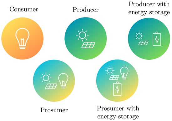
Figure 1.
Entity types in the considered community.
The set of indexes of users employing a storage system is denoted by .
We assume that the renewable energy produced by prosumers is first employed to compensate for the internal load, while the remaining amount can be charged into storage. For this reason, only the difference between generation and load is considered in the mathematical formulation. Let
be the variable denoting this difference; then, the energy that can be employed to charge a storage system between t and is
which is equivalent to the energy surplus provided by the renewable source. To streamline the reasoning, we suppose that the energy storage units are such that they can always store the energy surplus () whenever needed.
2.1. Energy Storage Model
For a given entity (), the energy stored at time t is defined by the variable , whose time evolution is defined by the following equation:
where the initial condition is assumed to be . In (3), denotes the storage charging/discharging efficiency, whereas and denote the energy charged and discharged between t and , respectively. Constraints involving the charging energy can be modeled as
which enforces being positive and not exceeding . Concerning , one has
which enforces and as positive quantities. Finally, to avoid simultaneous charging and discharging, the following constraints need be enforced:
2.2. Prosumer Load Balancing
Before performing the optimal community operation, we assume that prosumers first use their own storage units to comply with their needs. For this reason, their renewable energy surplus is first employed by the storage system to balance the load in periods of lower generation. The remaining energy can be used for community purposes.
Let be the profile obtained after performing this load-balancing operation. For instance, a possible profile () is depicted in Figure 2.
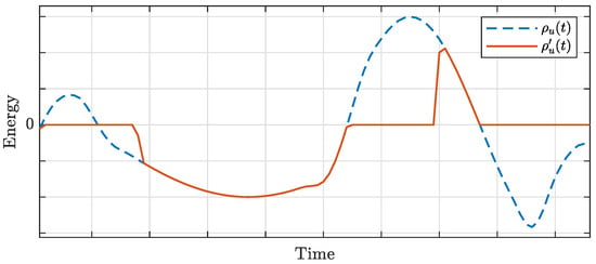
Figure 2.
Profile () and balancing profile () for a given prosumer ().
Generation exceeds load during periods where , while when , the load is greater than generation. It is worthwhile to note that the total renewable generation used for this operation (the area where ) is greater than the overall energy required by loads (the area where ) due to the round-trip efficiency () of storage.
The balancing operation involves only prosumers equipped with a storage device. Thus, profiles involving consumers, producers and prosumers without storage units remain unchanged, i.e., .
Since new energy profiles are generated, constraints involving the storage units are modified according to . Therefore, is bounded as follows:
where
Remark 1.
The profile () is employed to perform the optimal community operation. Once the optimal solution is computed, the actual storage schedule involves the sum of two terms. The former is the solution providing , while the latter is that related to community optimization. Moreover, no simultaneous charging and discharging may happen by merging the two solutions. In fact, when , the community solution cannot ask for storage charging. On the contrary, when , storage is not used for the load-balancing operation; hence, it can be either charged or discharged depending on the stored energy (see Figure 2).
2.3. Community-Level Aggregation
In the following, computations aimed at aggregating at the community level, the introduced quantities are reported. Let us focus on the aggregation of load and generation. At a given time (t), the overall energy demand of all entities is
while the renewable energy produced in the community is
Notice that consumers and producers always contribute to and , respectively. On the other hand, prosumers contribute either to if, at time t, a load excess occurs () or to if there is a renewable generation surplus ().
In an incentive-based REC, a monetary incentive is provided on the basis of the self-consumed energy within the community. Let denote community self-consumption. Its mathematical expression can be written as
which represents the energy demand that is fulfilled by renewable sources.
The aggregation of storage systems is performed similarly to the computations of and . Specifically, at a given time (t), the energy stored in all storage facilities is
while the charging and discharging energies are
Constrains with respect to and need to be managed, too. The overall storage dynamics can be expressed as
whereas and are bounded as follows:
where
A direct consequence of managing the storage units within the community is that the renewable generation profile is modified. The actual renewable generation () in the community is the result of the following operation:
Therefore, the REC’s self-consumption needs to be adapted accordingly. Let denote community self-consumption using storage systems; then, one has
Remark 2.
In the following, a formulation for optimal community operation is provided using aggregated quantities. Moreover, a procedure for computing a distributed feasible solution starting from the aggregated one is provided in the next sections.
3. Optimal Storage Operation
In this section, the optimal storage operation problem is introduced. We assume that the community’s primary objective is to minimize the energy bill over the time interval of through the incentive gained by self-consumption. Storage operation is optimized by minimizing the following objective function:
where , and k are the energy purchase price, selling price and unitary incentive, respectively, for self-consumption.
In this setup, we suppose that the storage units are empty at the beginning and at the end of the considered time interval (). The constraint enforcing such a condition is
Then, the optimal storage command is the minimizer of the following optimization problem:
Problem 1.
where is the vector containing the optimal charging and discharging control signals, i.e.,
Energy Storage Convenience
In order to show when it is convenient to have storage systems inside the community, we first introduce a lemma that provides an equivalent formulation of Problem 1.
Proof of Lemma 1.
Since the optimization constraints are the same as for Problem 1, the equivalence is proven by showing that objective functions I and J are equivalent.
To this end, let us first focus on storage (), which is equivalent to
where the initial condition is not considered, since . On the other hand, constraint (22) can be written as follows:
Therefore, according to (19) and (29), the renewable generation over the optimization period can be written as
Substituting I into the objective function, one has
In (31), the terms involving and do not depend on the control signals ( and ). Thus, it is possible to consider the equivalent objective function as follows:
which concludes the proof. □
The convenience of community storage units relies on their optimal coordination, leading to reduced costs compared to not using them. In other words, if no storage units are involved in community operations, then the optimal solution to Problem 1 is trivially found by setting for all . Thus, the following theorem provides a threshold value for the incentive (k), dictating when storage systems are not worthwhile for community operation.
Theorem 1.
If , then the optimal solution of Problem 1 is .
Proof of Theorem 1.
Let us consider the equivalent optimization problem introduced in Lemma 1. Moreover, let and the value of J for such a solution. It holds that
Thus, the objective function can be bounded from below as follows:
According to the hypothesis of , one has
Since the solution achieves the lower bound, such a solution is optimal. □
Remark 3.
Theorem 1 provides a threshold value on k denoting the convenience of using storage. In fact, if the best solution does not require the use of storage to minimize the REC cost. In this case, the cost of the energy losses that occur during the charging/discharging operations cannot be compensated for by the increment of the monetary incentive received by the REC, so the optimal solution of Problem 1 does not call for the presence of batteries. On the contrary, if , storage systems can be effectively adopted to provide a lower cost at the community level. Notice that costs associated with the storage, like degradation and replacement costs, are not considered in this analysis, since they are related to single entities and not to the REC.
4. Distributed Solution Derivation
The solution of Problem 1 considers only aggregated quantities of community storage systems and does not involve the charging/discharging commands of each single storage unit. In this section, the derivation of a distributed solution for the operation of storage facilities is reported.
First, it is worth noting that the solution of Problem 1 is such that and cannot be simultaneously greater than 0, as proven in the following lemma.
Lemma 2.
Let and , be the optimal charging and discharging control signals for Problem 1. Then,
Proof of Lemma 2.
By contradiction, assume that at a given time (t), one has , . Suppose . Let us consider the following control signals: . According to (19), one has and . Therefore, the term of the sum in objective function (21) is the same for both solutions. However, the state of charge of storage at time for the two strategies is
Then,
Therefore, by applying and , the cost function until time t is the same as applying , but the state of charge of storage is greater. Since (22) requires that, at time T, the storage must be empty, such a surplus of energy is sold in the next time steps, providing a final cost smaller than that provided by , leading to a contradiction.
A similar argument holds for the case of . □
Let the optimal solution of Problem 1 be given, and let and be the optimal charging and discharging commands, respectively, at a given time (t). According to (28), the optimal value of the stored energy at time t follows
Let us introduce the following quantities that denote how close the charging and discharging commands are to their respective upper bounds:
It is worthwhile to remark that all the quantities involved in (44) and (45) are known, since the optimal solution of Problem 1 is assumed to be given. The optimal charging/discharging commands of each single storage unit of the REC are provided by the following theorem.
Theorem 2.
Proof of Theorem 2.
At a given time (t), the following set of equations holds:
where the last equation follows from the two previous ones.
It remains to be proven that that constraints (4)–(6) are satisfied. According to (16) and (17), it holds that
hence,
According to Lemma 2, one has . This last implication ensures that . □
Remark 4.
Theorem 2 makes it possible to compute a solution for each single storage unit starting from the aggregated one. Specifically, this solution partitions the optimal aggregated command to ask users the for same commitment for community operation. In other words, the ratio between the charging/discharging command and its corresponding upper bound is the same for each entity of the REC.
5. Numerical Results
To show how the proposed approach works, two illustrative examples and a large-scale example are reported. The optimization period spans 24 h, with a sampling time 15 min, i.e., . The energy efficiency of the storage units is set to , while grid prices are supposed to be €/kWh and €/kWh, and the incentive is assumed to be €/kWh. It is worth noting that since €/kWh, according to Theorem 1, the value of the incentive (k) makes storage utilization in the community convenient. Simulations were run using MATLAB 2023b, and Problem 1 was formulated using YALMIP R20210331 [25] and solved by CPLEX [26].
Example 1.
Load-balancing operation.
A simplified community structure involving one consumer and one prosumer is considered to show how the load-balancing operation is embedded in the optimal solution of community operation. Load and generation profiles of the entities are depicted in Figure 3.
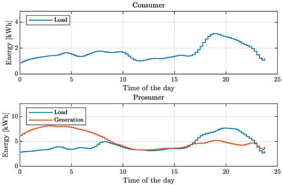
Figure 3.
Example 1: load and generation profiles of the community entities.
The presented profiles were derived to resemble the renewable generation of a wind turbine and a residential load.
After performing the load-balancing operation explained in Section 2.2, the prosumer profile () is obtained (see Figure 4).
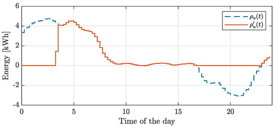
Figure 4.
Example 1: prosumer profile () and the resulting profile () after performing the load-balancing operation.
Then, aggregating at the community level, load and generation profiles are computed, as reported in Figure 5.
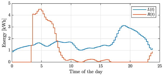
Figure 5.
Example 1: load () and generation (R(t)) at the community level after performing prosumer load balancing.
The aggregated profile shows a renewable surplus during the time window ranging from 3:30 to 7:45, whereas excess load occurs in the other time periods.
The optimal solution of Problem 1 is such that the storage unit of the prosumer is employed to fully exploit the energy surplus to compensate for part of the load when . This behavior is evident in the storage dynamics and related charging and discharging control signals shown in Figure 6.
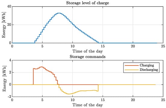
Figure 6.
Example 1: Storage level of charge and related charging and discharging control signals for community operation.
Moreover, the obtained storage schedule is such that self-consumption () is maintained/enhanced when the storage is charging/discharging, as shown in Figure 7.
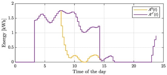
Figure 7.
Example 1: Self-consumption profiles ( and ).
Thus, the obtained profile initially follows the load until the storage is fully discharged; then, the self-consumption pattern resembles the generation profile (). The optimal solution allows the community to save about EUR 2.16 with respect to EUR 36.77 when no storage is used for the community operation. Most notably, energy self-consumption increases by about 78% when using storage units to reduce community cost. Community costs and incentives concerning all the simulated setups are summarized in Table 1.

Table 1.
Community costs and incentives.
Finally, we show how storage is actually used within the community. Clearly, the storage system is first employed to balance part of the prosumer load; then, the remaining renewable surplus is used to reduce the community cost. Thus, part of the storage schedule is devoted to two different kinds of operations involving different charging/discharging commands. The control signals used for load balancing and for community operation are reported in Figure 8.
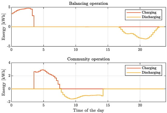
Figure 8.
Example 1: charging and discharging command of storage for the load-balancing operation and for community operation.
As depicted, the charging and discharging control signals do not overlap. Therefore, the actual storage operation is obtained by merging the storage commands for both the load-balancing and community operations. The merged storage schedule is reported in Figure 9.
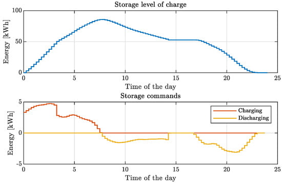
Figure 9.
Example 1: storage level of charge and related charging and discharging control signals for the load-balancing and the community operations.
Example 2.
Distributed solution derivation.
In this example, we show how the distributed solution behaves when two storage units are involved in community operation. For this purpose, we consider a community structure involving one consumer, one prosumer and one producer.
Entity profiles of load and generation are depicted in Figure 10, whereas the related profiles aggregated at the community level are depicted in Figure 11.
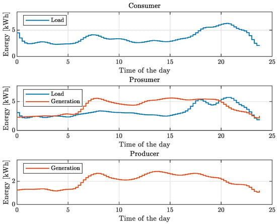
Figure 10.
Example 2: load and generation profiles of the community entities.
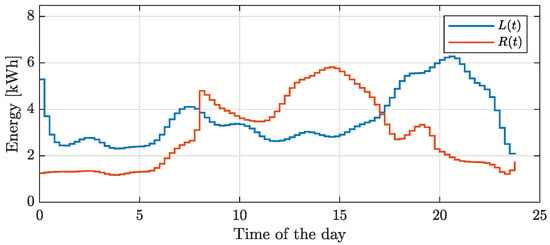
Figure 11.
Example 2: load () and generation (R(t)) at the community level after performing prosumer load balancing.
Intuitively, the optimal storage operation exploits the renewable surplus occurring in the time period ranging from 08:15 to 17:00 to match part of the load excess in the last period of the day. The optimal storage operation is shown in Figure 12.
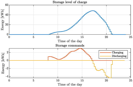
Figure 12.
Example 2: storage level of charge and related charging and discharging control signals for community operation.
Then, by exploiting Theorem 2, the distributed solution is obtained on the basis of the aggregated one. In particular, the resulting storage schedules are depicted in Figure 13.
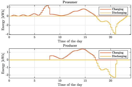
Figure 13.
Example 2: distributed solution involving charging and discharging control signals for community operation.
It is worthwhile to remark that the two solutions differ, since the prosumer storage is first used to the perform load self-balancing operation, then for community operation.
Concerning cost performance, the proposed algorithm reduces the community cost by about 8.5% with respect to the solution not using storage in the community, while the community incentive increases by about 19%. This increase is highlighted by observing the self-consumption profiles ( and ) in Figure 14.
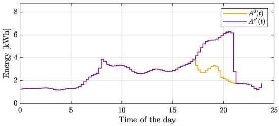
Figure 14.
Example 2: self-consumption profiles ( and ).
Example 3.
Large-scale scenario.
In this section, a large-scale example is reported. An REC comprising 30 consumers, 20 prosumers and 10 producers is considered, where 10 prosumers and 7 producers are assumed to be equipped with storage systems. Simulations are performed for 10 days, using real historical data concerning load and generation. Note that since all the entities belong to the same neighborhood, we consider a base profile for all members involving renewable generation scaled by a suitable constant. For prosumers, this constant is sized on the basis of the related load, whereas it is the peak production value if it involves producers. The generation profile providing renewable production for all entities is taken from a real photovoltaic plant, and it is depicted in Figure 15.
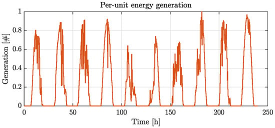
Figure 15.
Generation profile per energy unit of the large-scale example.
In Figure 16, load and generation profiles of three entities are reported, while in Figure 17, the aggregated profiles at the community level are depicted.
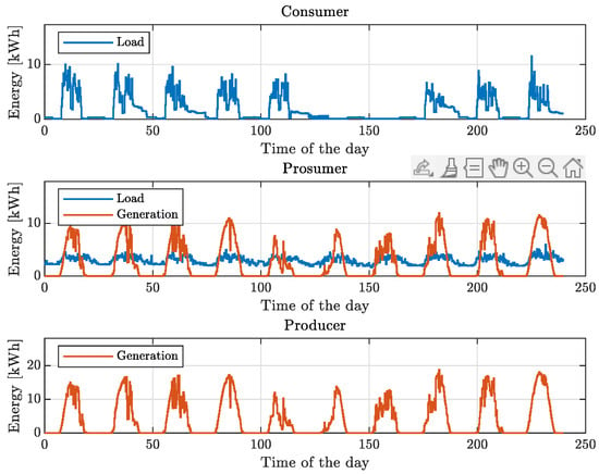
Figure 16.
Example 3: load and generation profiles of three community entities.
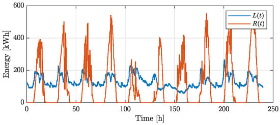
Figure 17.
Example 3: load () and generation (R(t)) at the community level after performing prosumer load balancing.
Similarly to the previous cases, by employing the optimal solution of the storage operation problem, the energy surplus incoming from renewable generation is stored in the storage units, then used in later periods. A comparison of the self-consumption profiles between the optimal storage operation and the solution without using storage systems is shown in Figure 18.
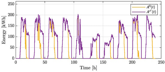
Figure 18.
Example 3: self-consumption profiles ( and ).
Concerning computational aspects, the proposed approach requires about 3.43 s to solve all 10 days of simulation on an i7-11700k@3.60 GHz with 32 GB of RAM.
Discussion
Focusing on the results of the large-scale example reported in Table 1, it follows that the proposed approach is capable of reducing the community cost by about 9.2% compared to a strategy that does not optimize the behavior of the storage units. From a self-consumption perspective, the optimal strategy coordinates the operation of the storage systems in order to match energy consumption with renewable generation. Notably, on average, the self-consumption is increased by about 44%, providing significant benefits from an incentive and sustainability standpoint.
The obtained results are in line with European energy policies and directives [2], since the proposed approach enables environmental, economic and social benefits for the community members. In fact, by suitably coordinating storage units, it is possible to reduce the cost of the whole community system, while substantial environmental benefits are attained through increased renewable self-consumption.
6. Conclusions
An optimization framework for optimal storage operation in RECs is proposed. By aggregating quantities related to load/generation profiles and energy storage facilities, and optimization problem with the aim of minimizing the community cost was formulated. The optimal storage schedule was computed through the solution of a low-complexity linear program, which allows one to derive analyses in feasible time frames. Moreover, a condition on the self-consumption incentive is derived to define the threshold at which installed storage systems become beneficial for the community. By exploiting optimality conditions of the introduced problem, an optimal distributed solution for storage operation is finally obtained.
Numerical results show how the optimal solution behaves in different settings. In all the considered examples, the optimal storage schedule makes it possible to considerably increase community self-consumption. Most notably, in the considered large-scale scenario, energy self-consumption is increased by about 44%, whereas the computation time remains negligible compared to the sampling time.
Future work will focus on deriving an explicit solution to the reported optimization problem and adapting the proposed framework to more complex scenarios. Such scenarios will be focused on addressing uncertainty in load and generation, price sensitivity to load demand and the integration of additional community facilities such as different storage devices (e.g., hydrogen, supercapacitors) and electric vehicles.
Author Contributions
Conceptualization, M.C. and G.G.Z.; methodology, M.C.; software, G.G.Z.; validation, A.V.; writing—original draft preparation, G.G.Z.; writing—review and editing, M.C.; supervision, A.V.; funding acquisition, M.C. and A.V. All authors have read and agreed to the published version of the manuscript.
Funding
This work was supported by (i) the Italian Ministry for Research within the framework of the 2022 Program for Research Projects of National Interest (PRIN) under Grant 2022K4CLL3 and (ii) the University of Siena within the framework of the Piano per lo Sviluppo per la Ricerca (PSR) 2023, F-NEW FRONTIERS.
Institutional Review Board Statement
Not applicable.
Informed Consent Statement
Not applicable.
Data Availability Statement
The original contributions presented in the study are included in the article, further inquiries can be directed to the corresponding author.
Conflicts of Interest
The authors declare no conflicts of interest.
References
- European Commission. 2050 Long-Term Strategy. Available online: https://climate.ec.europa.eu/eu-action/climate-strategies-targets/2050-long-term-strategy_en (accessed on 29 April 2024).
- Directive (EU) 2019/944 of the European Parliament and of the Council. Off. J. Eur. Union 2019, L, 125–199.
- Ceglia, F.; Marrasso, E.; Pallotta, G.; Roselli, C.; Sasso, M. The State of the Art of Smart Energy Communities: A Systematic Review of Strengths and Limits. Energies 2022, 15, 3462. [Google Scholar] [CrossRef]
- Martirano, L.; Rotondo, S.; Kermani, M.; Massarella, F.; Gravina, R. Power Sharing Model for Energy Communities of Buildings. IEEE Trans. Ind. Appl. 2021, 57, 170–178. [Google Scholar] [CrossRef]
- Hoicka, C.E.; Lowitzsch, J.; Brisbois, M.C.; Kumar, A.; Ramirez Camargo, L. Implementing a just renewable energy transition: Policy advice for transposing the new European rules for renewable energy communities. Energy Policy 2021, 156, 112435. [Google Scholar] [CrossRef]
- Cornélusse, B.; Savelli, I.; Paoletti, S.; Giannitrapani, A.; Vicino, A. A community microgrid architecture with an internal local market. Appl. Energy 2019, 242, 547–560. [Google Scholar] [CrossRef]
- Zanvettor, G.G.; Casini, M.; Giannitrapani, A.; Paoletti, S.; Vicino, A. Optimal Management of Energy Communities Hosting a Fleet of Electric Vehicles. Energies 2022, 15, 8697. [Google Scholar] [CrossRef]
- Di Silvestre, M.L.; Ippolito, M.G.; Sanseverino, E.R.; Sciumè, G.; Vasile, A. Energy self-consumers and renewable energy communities in Italy: New actors of the electric power systems. Renew. Sustain. Energy Rev. 2021, 151, 111565. [Google Scholar] [CrossRef]
- Lilliu, F.; Reforgiato Recupero, D.; Vinyals, M.; Denysiuk, R. Incentive mechanisms for the secure integration of renewable energy in local communities: A game-theoretic approach. Sustain. Energy, Grids Netw. 2023, 36, 101166. [Google Scholar] [CrossRef]
- Cielo, A.; Margiaria, P.; Lazzeroni, P.; Mariuzzo, I.; Repetto, M. Renewable Energy Communities business models under the 2020 Italian regulation. J. Clean. Prod. 2021, 316, 128217. [Google Scholar] [CrossRef]
- Rodríguez-Vilches, R.; Martín-Martínez, F.; Sánchez-Miralles, Á.; Gutiérrez de la Cámara, J.R.; Muñoz Delgado, S. Methodology to assess prosumer participation in European electricity markets. Renew. Sustain. Energy Rev. 2024, 191, 114179. [Google Scholar] [CrossRef]
- Lazzari, F.; Mor, G.; Cipriano, J.; Solsona, F.; Chemisana, D.; Guericke, D. Optimizing planning and operation of renewable energy communities with genetic algorithms. Appl. Energy 2023, 338, 120906. [Google Scholar] [CrossRef]
- Ceglia, F.; Esposito, P.; Faraudello, A.; Marrasso, E.; Rossi, P.; Sasso, M. An energy, environmental, management and economic analysis of energy efficient system towards renewable energy community: The case study of multi-purpose energy community. J. Clean. Prod. 2022, 369, 133269. [Google Scholar] [CrossRef]
- Stentati, M.; Paoletti, S.; Vicino, A. Optimization of energy communities in the Italian incentive system. In Proceedings of the 2022 IEEE PES ISGT Europe, Novi Sad, Serbia, 10–12 October 2022; pp. 1–5. [Google Scholar]
- Parreño-Rodriguez, A.; Ramallo-González, A.P.; Chinchilla-Sánchez, M.; Molina-García, A. Community energy solutions for addressing energy poverty: A local case study in Spain. Energy Build. 2023, 296, 113418. [Google Scholar] [CrossRef]
- Battaglia, V.; Vanoli, L.; Zagni, M. Economic benefits of Renewable energy communities in smart districts: A comparative analysis of incentive schemes for NZEBs. Energy Build. 2024, 305, 113911. [Google Scholar] [CrossRef]
- D’Adamo, I.; Gastaldi, M.; Koh, S.L.; Vigiano, A. Lighting the future of sustainable cities with energy communities: An economic analysis for incentive policy. Cities 2024, 147, 104828. [Google Scholar] [CrossRef]
- Cutore, E.; Volpe, R.; Sgroi, R.; Fichera, A. Energy management and sustainability assessment of renewable energy communities: The Italian context. Energy Convers. Manag. 2023, 278, 116713. [Google Scholar] [CrossRef]
- Sousa, J.; Lagarto, J.; Camus, C.; Viveiros, C.; Barata, F.; Silva, P.; Alegria, R.; Paraíba, O. Renewable energy communities optimal design supported by an optimization model for investment in PV/wind capacity and renewable electricity sharing. Energy 2023, 283, 128464. [Google Scholar] [CrossRef]
- Fan, G.; Liu, Z.; Liu, X.; Shi, Y.; Wu, D.; Guo, J.; Zhang, S.; Yang, X.; Zhang, Y. Energy management strategies and multi-objective optimization of a near-zero energy community energy supply system combined with hybrid energy storage. Sustain. Cities Soc. 2022, 83, 103970. [Google Scholar] [CrossRef]
- Cruz-De-Jesús, E.; Martínez-Ramos, J.L.; Marano-Marcolini, A. Optimal Scheduling of Controllable Resources in Energy Communities: An Overview of the Optimization Approaches. Energies 2023, 16, 101. [Google Scholar] [CrossRef]
- Malik, S.; Duffy, M.; Thakur, S.; Hayes, B.; Breslin, J. A priority-based approach for peer-to-peer energy trading using cooperative game theory in local energy community. Int. J. Electr. Power Energy Syst. 2022, 137, 107865. [Google Scholar] [CrossRef]
- Autorità di Regolazione per Energia Reti e Ambiente. Elettricità: Nuovo Testo Integrato Sull’autoconsumo Diffuso per Edifici, Condomini e Comunità Energetiche. Available online: https://www.arera.it/comunicati-stampa/dettaglio/it/com-stampa/23/230104 (accessed on 29 April 2024).
- Gestore Servizi Energetici. Regole Tecniche per L’accesso al Servizio di Valorizzazione e Incentivazione Dell’energia Elettrica Condivisa. Available online: https://www.gse.it/servizi-per-te/news/comunit%C3%A0-di-energia-rinnovabile-e-gruppi-di-autoconsumatori-aggiornate-le-regole-tecniche-per-l%E2%80%99accesso-al-servizio (accessed on 29 April 2024).
- Löfberg, J. YALMIP: A Toolbox for Modeling and Optimization in Matlab. In Proceedings of the CACSD Conference, Taipei, Taiwan, 2–4 September 2004; pp. 284–289. [Google Scholar]
- IBM Corporation. IBM ILOG CPLEX Optimization Studio—User’s Manual Version 12 Release 6. Available online: https://public.dhe.ibm.com/software/products/Decision_Optimization/docs/pdf/usrcplex.pdf (accessed on 29 April 2024).
Disclaimer/Publisher’s Note: The statements, opinions and data contained in all publications are solely those of the individual author(s) and contributor(s) and not of MDPI and/or the editor(s). MDPI and/or the editor(s) disclaim responsibility for any injury to people or property resulting from any ideas, methods, instructions or products referred to in the content. |
© 2024 by the authors. Licensee MDPI, Basel, Switzerland. This article is an open access article distributed under the terms and conditions of the Creative Commons Attribution (CC BY) license (https://creativecommons.org/licenses/by/4.0/).