Article

Evaluation of Efficiency Enhancement in Photovoltaic Panels via Integrated Thermoelectric Cooling and Power Generation

by
Muhammad Faheem
1,
Muhammad Abu Bakr
1,*,
Muntazir Ali
1,
Muhammad Awais Majeed
1,
Zunaib Maqsood Haider
2 and
Muhammad Omer Khan
3,*
1
Department of Electrical Engineering, National University of Technology, Islamabad 44000, Pakistan
2
Department of Electrical Engineering, The Islamia University of Bahawalpur, Bahawalpur 63100, Pakistan
3
Department of Electrical Engineering & Technology, Riphah International University, Faisalabad 38000, Pakistan
*
Authors to whom correspondence should be addressed.
Energies 2024, 17(11), 2590; https://doi.org/10.3390/en17112590
Submission received: 21 March 2024 / Revised: 20 May 2024 / Accepted: 24 May 2024 / Published: 27 May 2024
(This article belongs to the Section A1: Smart Grids and Microgrids)

Abstract

:
Among renewable resources, solar energy is abundant and cost effective. However, the efficiency and performance of photovoltaic panels (PVs) are adversely affected by the rise in the surface temperature of solar cells. This paper analyzes the idea of utilizing thermoelectric modules (TEMs) to enhance the efficiency and performance of PV panels. The proposed hybrid solar thermoelectric generation (HSTEG) system employs TEMs as thermoelectric coolers (TECs) to enhance panel efficiency and as thermoelectric generators (TEGs) to convert excess heat into additional electricity. This study includes an extensive evaluation of the proposed idea using MATLAB Simulink and experimental validation in indoor as well as outdoor environments. The use of TECs for the active cooling of the PV system leads to an increase in its efficiency by 9.54%. Similarly, the passive cooling by TECs along with the additional power generated by the TEGs from the excessive heat led to an increase in the efficiency of the PV system of 15.50%. The results demonstrate the HSTEG system’s potential to significantly improve PV panel efficiency and energy generation, offering a promising avenue for advancing solar energy technology.

1. Introduction

Electrical energy is a critical component of a nation’s infrastructure and plays a vital role in its economic growth and development [1]. It powers the manufacturing sector, supports transportation and communication networks, and enables the delivery of essential services, such as healthcare and education. Electrical energy is typically produced using various sources, including coal, oil, natural gas, and nuclear materials [2]. Unfortunately, these sources are gradually diminishing and contribute to pollution by discharging hazardous materials and harmful gases into the atmosphere and water [3]. Moreover, high operating costs, fuel expenses, and other factors hinder the affordable generation of electrical power from these sources [4]. Additionally, renewable energy sources are cost effective, enabling the production of affordable electricity [4]. In recent years, energy producers are shifting their focus toward renewable energy sources, such as solar, wind, hydropower, geothermal, biogas, etc., to offset the detrimental effects of conventional power generation [5].
Among renewable energy resources, solar energy is abundantly available and is considered the cheapest source of energy [6]. The sun on average provides 162,000 TW of solar radiation to the Earth [7]. However, solar energy is not properly utilized for efficient electrical power generation. The two prevalent methods of harnessing solar power for electricity are solar photovoltaic and solar thermal systems. In solar photovoltaics, incident photons on the PN junction of cells generate a potential difference, supplying electrical energy to the connected loads [8,9]. Solar thermal systems first convert photon energy into heat using optical concentrators and then utilize mechanical heat engines to produce electricity [10]. Solar photovoltaic panels can be categorized as monocrystalline and polycrystalline. Monocrystalline panels are made from a single crystal material, providing a uniform structure and higher efficiency (25–30%) [11]. In contrast, polycrystalline panels use multiple crystalline materials with an uneven atom distribution, resulting in a lower efficiency (16–20%) [12,13].
The energy produced by solar PV panels is dependent on several factors, such as solar radiation, panel temperature, the angle of the incident light, etc. Solar PV panels produce their rated electricity under standard operating conditions, including an irradiance of 1000 W/m2, a temperature of 25 °C, and an air mass of 1.5. Any deviation from these conditions can lead to reduced electrical output due to heat and irradiance losses [14,15]. As a rule of thumb, a 0.4 to 0.5% drop in solar cell efficiency occurs for each 1 °C increase above the standard test condition (STC) temperature, as heat significantly hampers power generation efficiency [16]. Similarly, exposure to high temperatures also causes the materials in a solar panel to degrade more quickly, leading to a shorter lifespan [17]. Therefore, different techniques for cooling PV panels and voltage generation from heat losses are used to enhance the efficiency and extend the lifespan of PV systems.
When solar radiation hits a PV panel, only a small portion of the incident irradiation is converted to electricity while the rest is absorbed and emitted as heat [18], leading to the panel overheating. Several studies have been conducted to determine the effect of water-spraying PV systems compared to that of traditional systems [19]. The degradation in the efficiency of the solar cells due to heating can be overcome by cooling the panels using a variety of methods, including water spraying [19], air cooling [20], concentrated PV [21], and phase-change materials (PCMs) [22]. That study models heat and mass fluxes using computational fluid dynamics in a system made up of an impure phase transition material located behind a solar panel. However, PCMs have a limited thermal conductivity, heat capacity, and lifespan. Additionally, compatibility issues of PCMs with solar systems may cause damage to the panels [22].Experimental results have shown that the cells’ power increases due to the water spraying over the photovoltaic cells [23]. However, water-based cooling methods cause corrosion and require a significant amount of water for cooling, which can be a concern in areas with limited water resources [24]. The effect of PCMs for maintaining the panel temperature close to ambient temperature is presented in [25].
Another method is using thermoelectric modules (TEMs) to remove excess heat from the solar panel to improve its efficiency. The cooling mechanism of the TEM, also known as a thermoelectric cooler (TEC), can be further improved by enhancing the heat transfer by passing an electric current through the thermoelectric elements. The TEC functions as a heat rejection device upon supplying a DC current, producing a temperature difference proportional to the applied current [26]. When there is a temperature difference on both sides of the TEM, it can be employed as a static thermoelectric generator (TEG) based on the principle of the Seebeck effect [15,27]. TEGs are well suited for thermal loss recovery and utilization, enabling extra power generation from solar PV waste heat [28,29].
Solar panels integrated with TEMs constitute a hybrid solar thermoelectric generation (HSTEG) setup, which offers an enhanced solar conversion efficiency and appealing attributes, including quiet and pollution-free operation, the lack of mechanical components, scalability, a straightforward setup, the ability to convert low-grade heat, and minimal maintenance needs [30]. A TEM is a solid-state device that incorporates a series of thermoelectric components consisting of a pair of p-type and n-type semiconductors and uses the Peltier effect [31] to transfer heat from one side of the device to the other. Furthermore, thermoelectric devices require minimal maintenance due to their lack of moving parts, ensuring longevity and exceling in extreme conditions like deserts [32]. The enhanced energy generated from the cooled solar panels by TECs combined with the output of TEGs is a feasible solution to improve the overall efficiency of solar PV systems. Recently, there has been an increasing level of interest in using HSTEGs to boost the power output of PV systems. In [33], a simple and idealized model of the PV-TEM system was investigated for the conversion of waste heat into electricity. An integrated solar–thermoelectric system was developed and its performance was evaluated under severe temperature conditions in [34]. Similarly, an efficiency comparison of a standalone PV system and hybrid solar–thermoelectric system for different kinds of energy storage designs is performed in [35].
A hybrid PV TEG system for precision agriculture was investigated by [36], in which a simulation of a PV array and TEG was conducted via MATLAB/Simulink R2021a for real environmental conditions to predict the output. The passive cooling technique was implemented in [37], in which a TEG coupled with a PV array and dual-axis solar tracking system was investigated. PV and PV + TEG system performances were analyzed in [38]. They also used a passive cooling technique to reduce the solar panel temperature. Three proposed systems—a standalone PV, PV + TEGs at the side of the solar panel, and PV + TEGs at the rear and side of the solar panel—are analyzed in [39], in which the overall efficiency of the combined PV + TEG system was higher than that of the standalone PV panel.
While previous research in this area has primarily relied on simulation-based approaches, a comparison of TEMs as coolers (active cooling) and TEMs as generators (passive cooling) has not been conducted so far in the literature. This research is primarily focused on studying the impact of temperature on the maximum power output of solar panels and ultimately increasing their lifespan, a topic that has been not been sufficiently covered for PV + TEM systems.
In this paper, thermoelectric modules (TEMs) are used as cooling and generation devices to enhance the efficiency of photovoltaic (PV) panels. The behavior of the modules is controlled for their operation as thermoelectric coolers (TECs) to cool the panel temperature or as thermoelectric generators (TEGs) to generate power from waste heat. The cooling mechanism reduces the panel temperature, which in turn, increases the efficiency of the panels. It is widely known that solar panel efficiency typically drops by about 0.5% for every 1 °C increase in temperature [16]. In this study, we actively lower the solar panel temperature and convert excess heat into additional electricity using thermoelectric modules. By dispersing the excess heat and maintaining optimal operating temperatures, our system increases the power output and extends the solar panel’s lifespan. The generation mechanism utilizes the heat losses in the panel to generate additional electricity, thus enhancing the overall efficiency of the system. To analyze the behavior of the proposed system under different operating conditions, it is modeled and simulated in MATLAB Simulink. Experimental evaluations are then carried out in an indoor environment under controlled parameters as well as an outdoor environment for performance validation. The rest of the paper is organized as follows: In Section 2, the model design for the proposed hybrid system is discussed in detail. A simulation analysis is provided in Section 3, while our experimental evaluation is presented in Section 4. The article is concluded in Section 5.

2. Model Design

In this section, the design of the proposed hybrid solar thermoelectric generation system is covered. Figure 1 depicts the hybrid solar thermoelectric generation system and heat transfer mechanism. Thermoelectric modules (TEMs) coupled with heat sinks are attached to the rear of the PV panel and used as cooling and power generation devices. When connected to solar arrays, these modules enhance system efficiency through the utilization of the Seebeck and Peltier effects. The possible number of TEMs that could be attached to a solar panel can be calculated with the help of the dimensions of the solar panel and thermoelectric module using Equations (1)–(3), as shown below:
A S = L S × W S
A T = L T × W T
N T S = A S A T
where A S , A T , and N T S are the area of the solar panel, the area of the TEM, and the number of TEMs on the back of the solar panel, respectively. The number of TEMs for multiple solar panels N P can be computed as follows:
N T S T = N P × N T S
where N T S T is the total number of TEMs on the backs of all the solar panels. The TEMs can be employed as cooling devices or power generation devices based on the input conditions. The fundamental equations of both devices are discussed in detail, which will further help us in modeling the hybrid systems.

2.1. Fundamental Equations for Thermoelectric Cooler (TEC)

The parameters that need to be considered for analyzing the behavior of a thermoelectric cooler (TEC) are explained below.

2.1.1. Peltier Coefficient

Applying a potential difference across a silicon-based thermoelectric module initiates electron migration towards holes, facilitating heat transfer from one module side to the other. Depending on the direction of the current, the junction will either be heated or cooled. The cooling impact on one side and the heating impact on the other side of the module vary directly with the applied current [40]. The Peltier coefficient can be calculated as follows [41]:
P m = V m a x T h
where V m a x is the maximum voltage that can be applied to the TEC, and Th is the temperature of the TEC’s hot side.

2.1.2. Internal Electrical Resistance

Since the cooling of a TEC depends on the amount of current passing through it, the resistance offered to the flow of the current is known as the internal electrical resistance. The resistance mainly depends on the temperature on the hot side of the TEC and varies as the temperature of the hot side changes. The internal resistance of a TEC is often mentioned on the manufacturer’s datasheet. For instance, for TEC-12706 (Tianqi Star Electronics Co., Shenzhen, China), if the temperatures of the hot side are 25 °C and 50 °C, the electrical resistances offered by the TEC are 1.98 Ω and 2.30 Ω, respectively. The internal electrical resistance for the thermoelectric cooler can be calculated as follows [41]:
R i n t = V m a x × T h T m a x I m a x × T h
where V m a x is the maximum voltage that can be applied to the TEC, T h is the temperature of the TEC’s hot side, and T m a x is the maximum temperature difference that can be generated through both sides of the TEC.

2.1.3. Thermal Conductance

Thermal conductance measures the ability of a TEC to conduct heat. Thermoelectric conductance mainly depends upon the temperature on the hot side of the TEC and the parameters that are given in the manufacturer’s datasheet, i.e., V m a x , I m a x , and T m a x . The thermoelectric conductance for the TEC can be computed as given below [41]:
K t h = T m a x I m a x × V m a x × 2 T h T h T m a x
On the other hand, the expression of the voltage V is noted as follows:
V = P m T + I R i n t
While the heat absorbed Q is given as follows:
Q = P m I T c 0.5 2 I R i n t T R t h
The efficiency can then be calculated as follows:
η = V · I Q

2.2. Fundamental Equations for Thermoelectric Generator (TEG)

Some of the parameters that need to be considered for analyzing the behavior of thermoelectric generators (TEGs) are elucidated below.

2.2.1. Seebeck Coefficient

The Seebeck coefficient has a significant impact on the voltage generated as a result of the temperature difference between the two sides of the TEG. The magnitude of voltage will increase with increasing Seebeck coefficient mean values, and vice versa. The Seebeck coefficients of the hot side ( S b h ) and cold side ( S b c ) as well as the mean value ( S b m ) of both sides can be computed using Equations (11)–(13), respectively [35,41].
S b h = S 1 T h + S 2 T h 2 2 + S 3 T h 3 3 + S 4 T h 4 4
S b c = S 1 T c + S 2 T c 2 2 + S 3 T c 3 3 + S 4 T c 4 4
S b m = S b h S b c Δ T
where S 1 , S 2 , S 3 , and S 4 are Seebeck coefficient constants. T h and T c represent the temperature of the hot and cold sides of the TEG, respectively, where Δ T = T h T c .

2.2.2. Internal Electrical Resistance

The temperature difference formed on the two sides of the TEG is the primary factor that affects the electrical resistance provided to the passage of the current. The value of the resistance for the TEG can be determined as follows [41]:
R i n t = V m 2 W m
Meanwhile, the current I , voltage V , and the efficiency η can be calculated using Equations (15)–(17), respectively [32,42], as follows:
I = T h T c R i n t 1 + m S m
V = S b m T h T c 2
η = I 2 R i n t q h
where q h is the head absorbed by the TEG on the hot side.

2.3. Scenarios

A thermoelectric module (TEM) can operate in two modes: as a thermoelectric cooler (TEC) based on the Seebeck effect and as a thermoelectric generator (TEG) based on the Peltier effect. For the analysis of the proposed hybrid solar thermoelectric generation system in the later sections of this paper, the following scenarios are modeled and discussed in detail.

2.3.1. Seebeck Mode (Passive Cooling)

In the Seebeck mode, also known as the thermoelectric generator (TEG) mode, a temperature difference is applied across the TEM, and the module generates a voltage as a result. The thermoelectric module has a cold side and a hot side. In this case, the cold side has been attached to the back of the solar panel, while the hot side is facing the ambient temperature. Moreover, aluminum heat sinks are attached to the hot side of the module for heat dissipation. Once the temperature of the panel rises, a temperature difference is created across the module, which helps to generate power from the TEG. Additionally, the cold side of the module pumps the heat from the solar panel to its hot side, which is dissipated by the heat sinks to the environment, ultimately cooling the solar panel. This cooling process helps increase the overall efficiency of the solar panel.

2.3.2. Peltier Mode (Active Cooling)

In the Peltier mode, also known as the thermoelectric cooler (TEC) mode, a voltage is applied across the TEM, and the device absorbs or releases heat as a result. This can be used to cool or heat a device, depending on the direction of the voltage applied. As mentioned, the cold side of the thermoelectric module has been attached to the solar panel’s back. Once we apply the voltage to the module, it acts as a cooler and reduces the temperature of the solar panel. The decrease in the temperature of the solar panel is directly proportional to the voltage applied across the module. By actively cooling the solar panel and maintaining a lower operating temperature, the output power of the solar panel can be increased. Solar cells tend to perform better at lower temperatures, and the reduction in heat-induced losses contributes to the higher overall efficiency of the panel.

3. Simulation Analysis

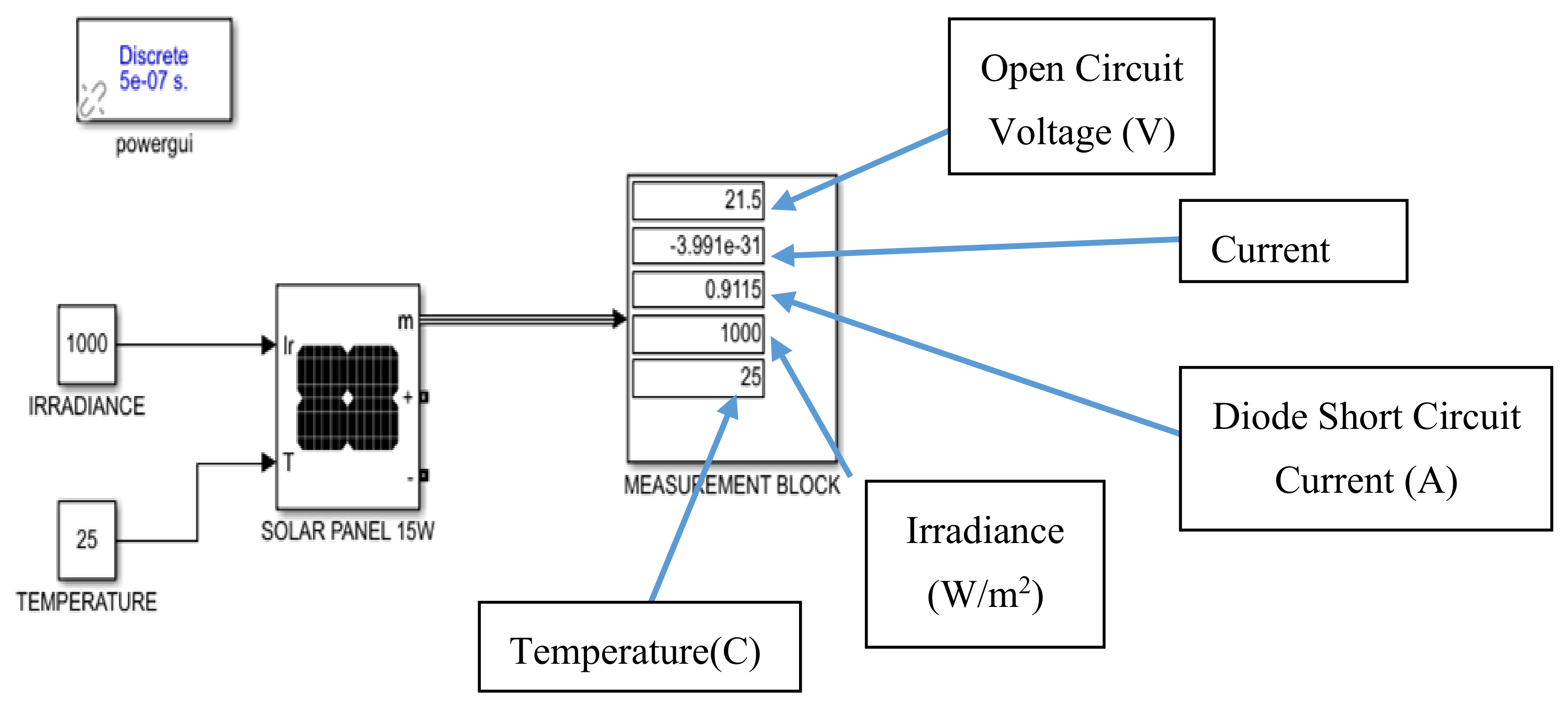
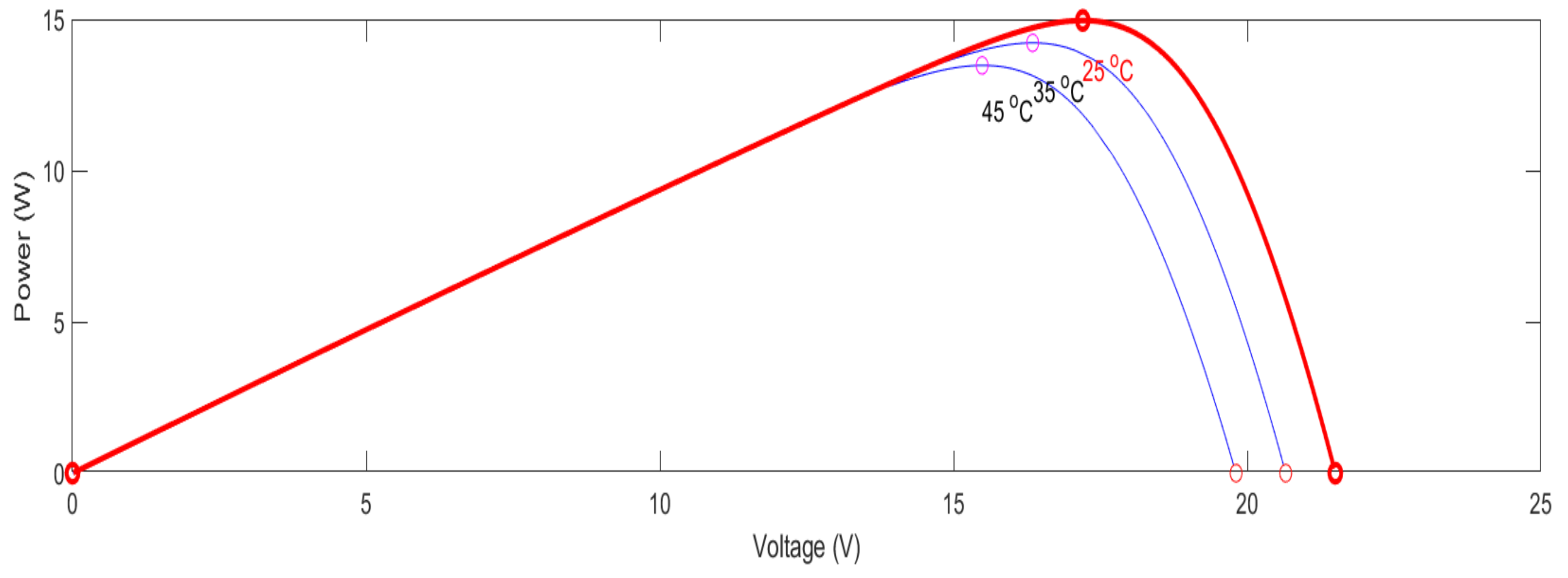
The Simulink layout of a solar panel is shown below in Figure 2. A 15 W solar panel receives rated irradiance of 1000 W/m2 at a temperature of 25 °C. As depicted in Figure 2, the simulation model provides the open circuit voltage (V) and current (A) at the output after receiving the operating parameters. Figure 3 shows the effect of temperature on the output power of the solar panel. The output power of the solar panel is plotted for 25 °C, 35 °C, and 45 °C. It can be observed that an increase in temperature reduces the output power of the solar panel. The solar panel achieves the maximum output power at 25 °C as depicted in Figure 3.

3.1. Thermoelectric Cooler (TEC)

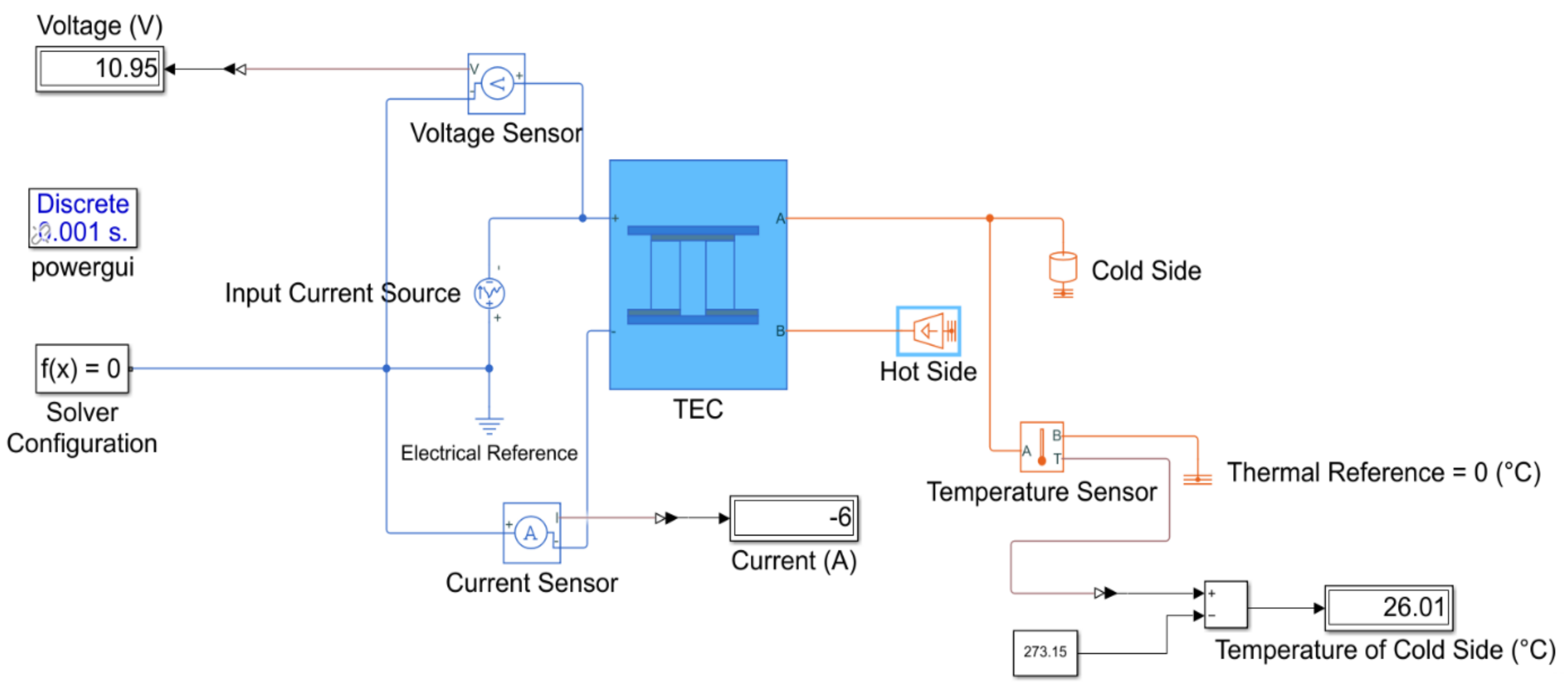
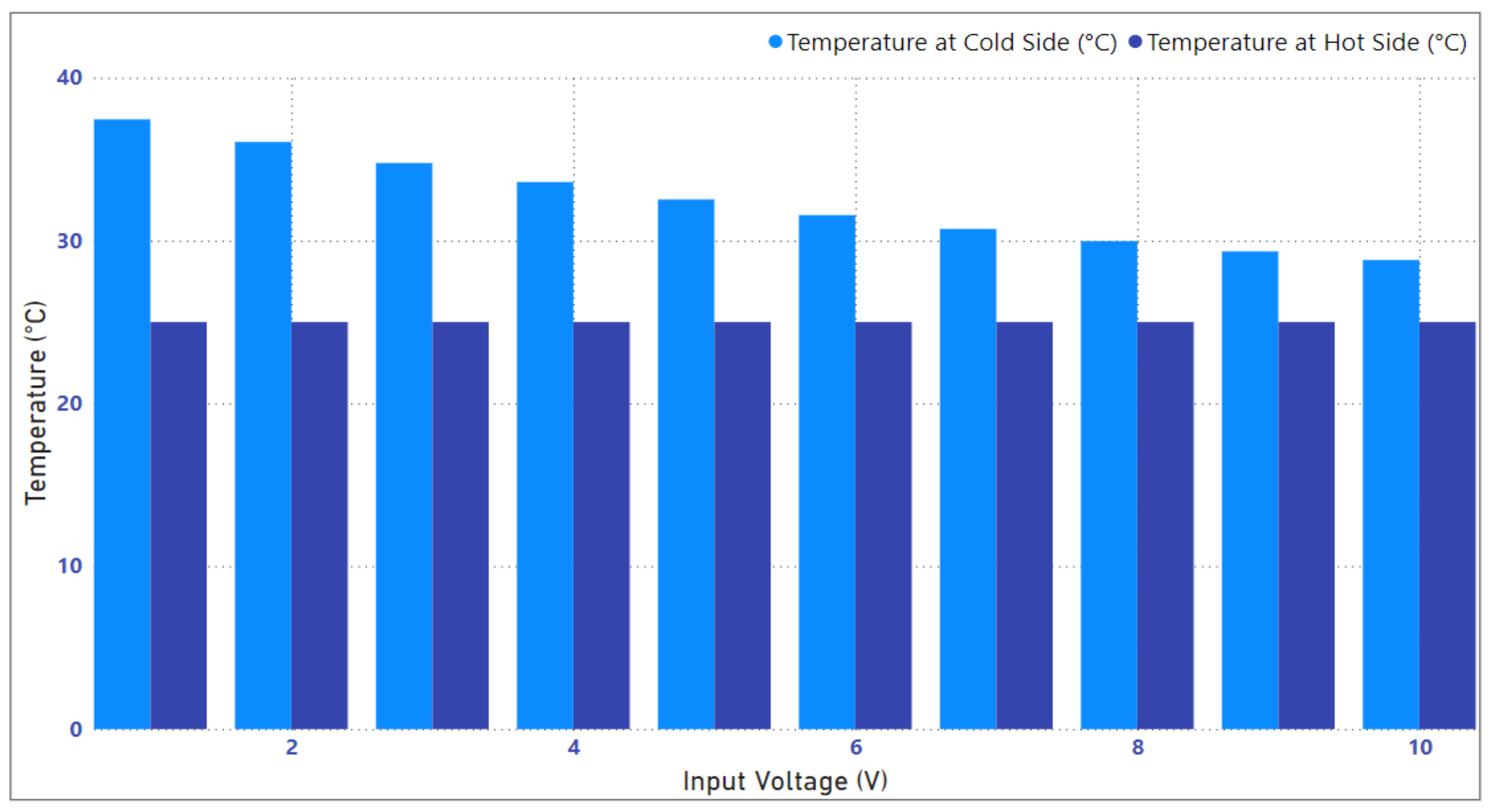
A simulation model of the thermoelectric cooler (TEC) is shown in Figure 4. To effectively analyze the behavior of the TEC, the input parameters were computed using the fundamental equations mentioned in Section 2.1. It can be observed from Figure 4 that the TEC receives a voltage and current of 10.95 V and 6 A, respectively, and the temperature of the TEC’s cold side is 26 °C. The hot side of the TEC is set to ambient temperature. On the cold side, the PV array surface temperature is added, which should be reduced by the TEC considering how much power is given at a particular instance. Figure 5 shows the effect of voltage on the cooling of the TEC. It can be observed that as the input voltage of the TEC increases, it decreases the temperature on the cold side. The temperature on the hot side remains constant due to the fact that, in the simulation, the heat sink is ideal and dissipates an infinite amount of heat.

3.2. Thermoelectric Generator (TEG)

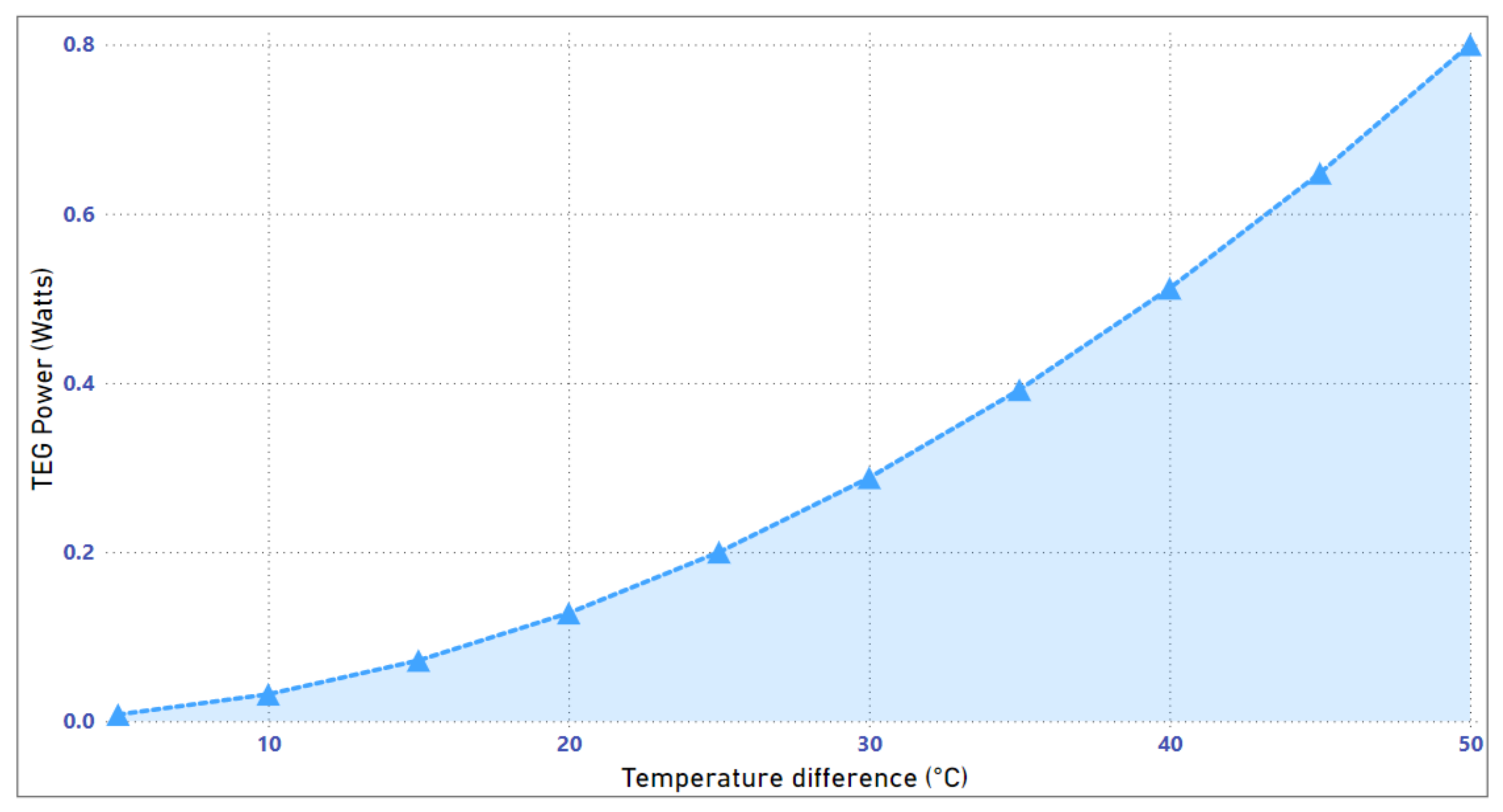
The MATLAB simulation model of the thermoelectric generator (TEG) is depicted in Figure 6. The TEG model was designed by calculating the input parameters using the fundamental equations mentioned in Section 2.2. The temperature on the hot side, the temperature on the cold side, the Seebeck coefficient, and the internal resistance of the TEG are computed as 75 °C, 25 °C, 0.096 V/K, and 7.2 Ω, respectively. It can be observed from Figure 6 that the TEG generates power based on the temperature difference between the hot and cold sides. The generated power is proportional to the temperature difference between the hot and cold sides. Figure 7 shows the effect of the temperature difference on the generated power. It can be observed that as the amount of temperature difference increases, the amount of power generated by the TEG increases. Moreover, the size of a TEG plays a significant role in determining its outputs and overall performance. A larger TEG typically allows for a larger surface area over which a temperature difference, known as a thermal gradient, can be maintained. This can result in higher power outputs as more heat energy can be converted into electricity through the Seebeck effect.

3.3. Thermoelectric Generator (TEG) with Solar Panel

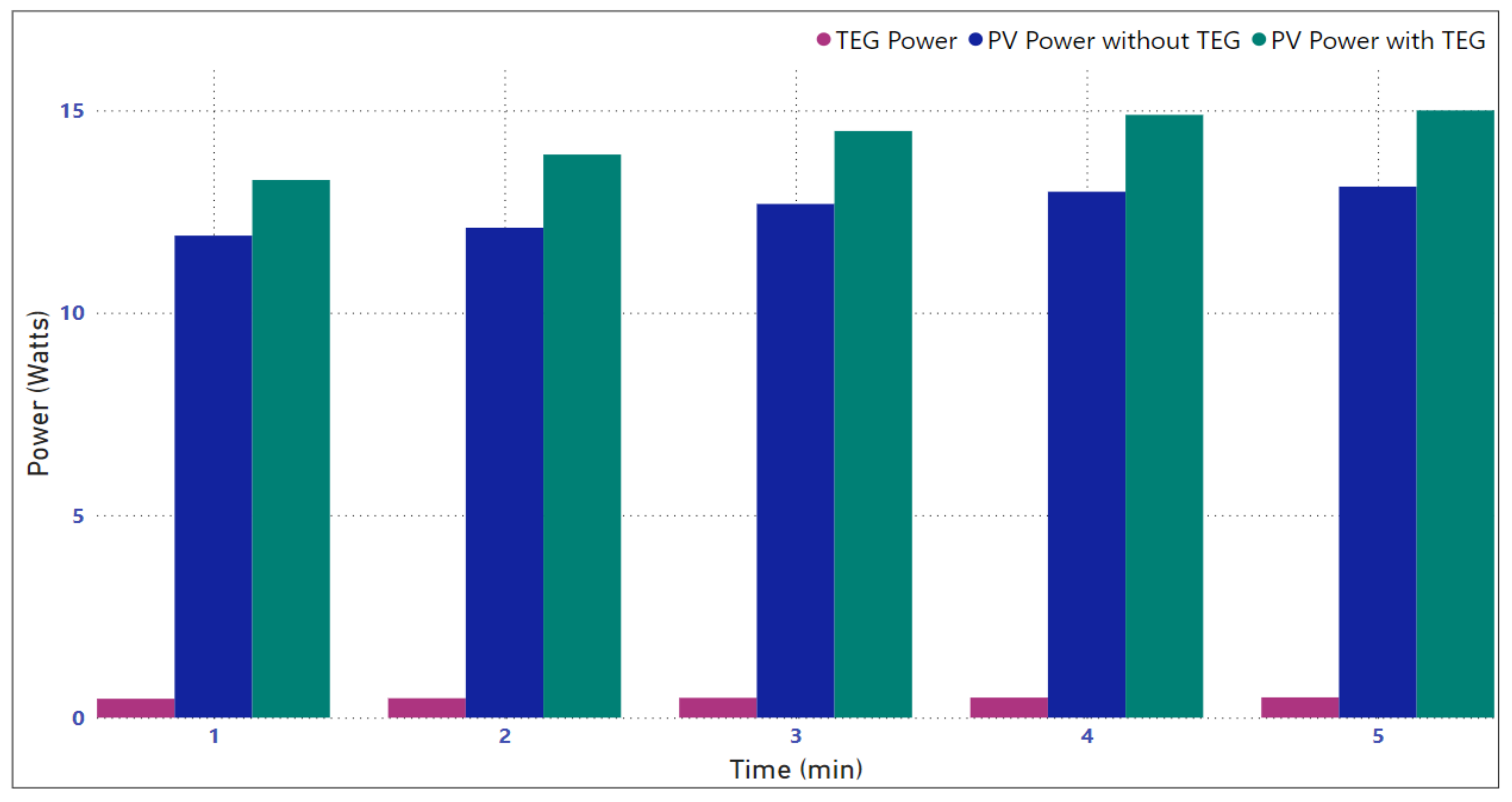
The MATLAB simulation of the integrated solar panel–TEG model is shown in Figure 8. The hybrid model is designed by attaching the cold side of the TEG to the back of the solar panel. The other side of the TEG is at ambient temperature and simulated by providing a temperature higher than the cold side. The temperature difference is created by setting the hot and cold sides of the TEG to different temperatures. As seen in Figure 8, this temperature difference is used by the TEG to generate additional power and consequently increase the efficiency of the solar panel. Figure 9 depicts a comparison of the output of solar panels with TEGs and without TEGs. It can be observed that the TEG utilizes the temperature difference between the solar panel and ambient temperature to produce power. Furthermore, placing the TEG on the back of the solar panel leads to an increase in the overall output power of the system. In Figure 9, the increase in the power of the PV+TEG system over time can be attributed to the simulation being conducted at different irradiance levels, ranging from lower to higher irradiance values. As the irradiance level increases, more solar energy is absorbed by the photovoltaic (PV) component of the system, leading to a higher electrical output from the PV cells. This increase in PV power output contributes to the overall power output of the PV+TEG system.

3.4. Thermoelectric Cooler (TEC) with Solar Panels

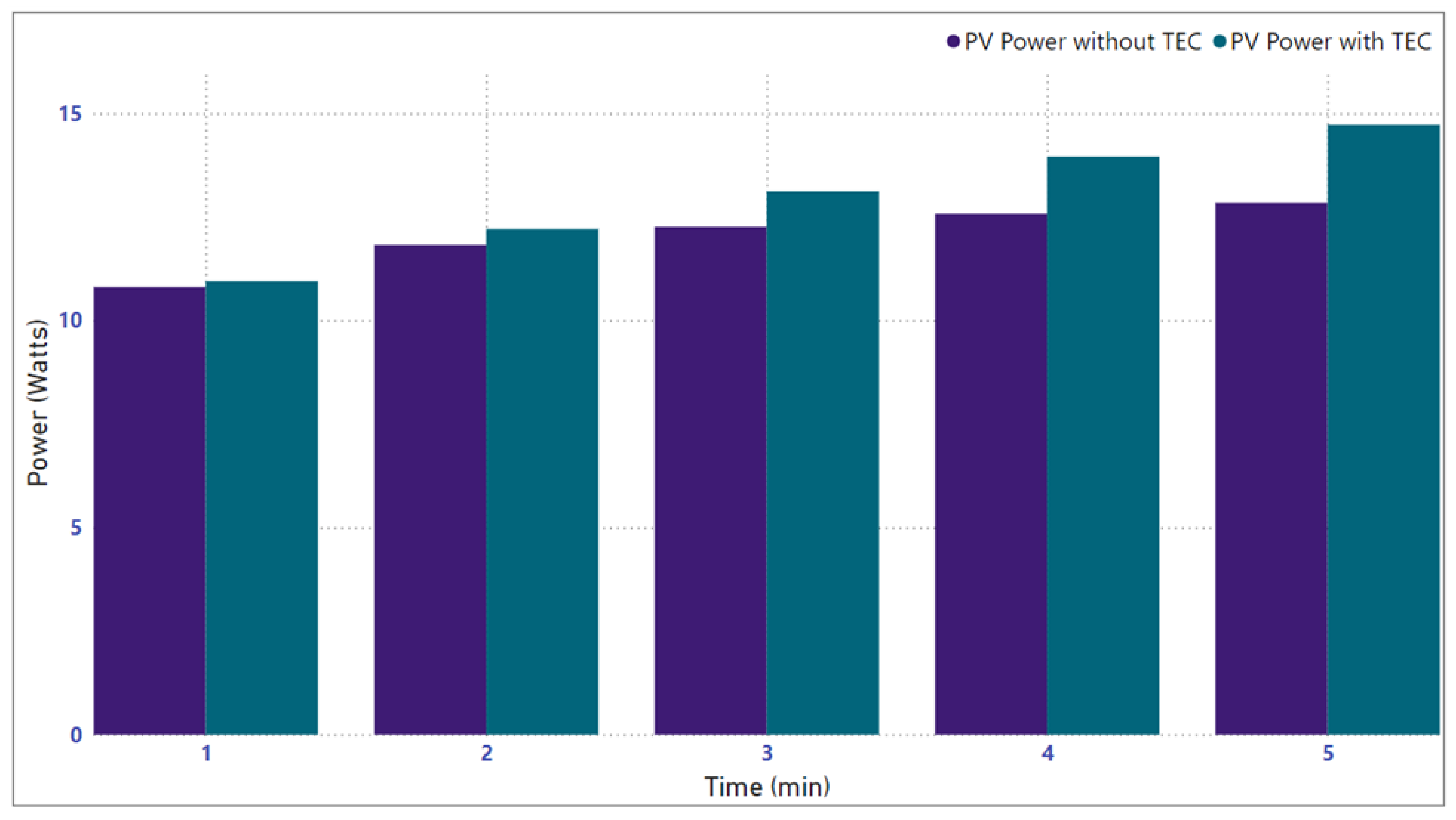
The MATLAB simulation of the hybrid model of a TEC with solar panels is shown in Figure 10. The cold side of the TEC is attached to the solar panel, which reduces the temperature of the panel. The cooling of the panel is dependent upon the power applied to the TEC module. The dissipation of heat from the solar panel through the cooling effect of the TEC increases its efficiency. Figure 11 shows a comparison of the solar panel output with TECs and without TECs. It can be observed in Figure 11 that using the TEC with solar panels leads to an increase in its output power. Since the temperature on the hot side of the TEC remains constant, we can observe a significant increase in the output power of the solar panel.

4. Experimental Results

The efficacy of the proposed HSTEG system is validated using experiments in a real environment. The system is analyzed by taking data from the HSTEG system in outdoor as well as indoor environments. The indoor environment is also considered a controlled environment because the parameters affecting the experimental setup can be controlled. Two solar panels, each of 15 W, were used in the experimental setup for a comparison of their PV output power: one with and one without thermoelectric modules (TEMs). Twenty TEMs were attached to the rear of the solar panel in series and parallel configurations. The modules were attached using thermoelectric paste, which helps the smooth flow of heat from the solar panel to the modules. Heat sinks were attached to the back of the TEMs with the help of thermoelectric paste, which dissipate the heat to the environment. Utilizing a thermoelectric module (TEM) in conjunction with a PV array is more advantageous than solely employing a heat sink as the TEM not only reduces the solar panel’s temperature but also generates power [42]. The primary purpose of the active cooling method is not to generate additional power, but rather to maintain a specific temperature or thermal performance. Since active cooling requires a power input, the focus is on temperature management and regulation rather than a net power gain.
The specifications of the equipment used in the experimental setup are provided in Table 1. Detailed discussions on the experiments in the controlled environment and outdoor environment are included below.

4.1. Indoor (Controlled) Environment

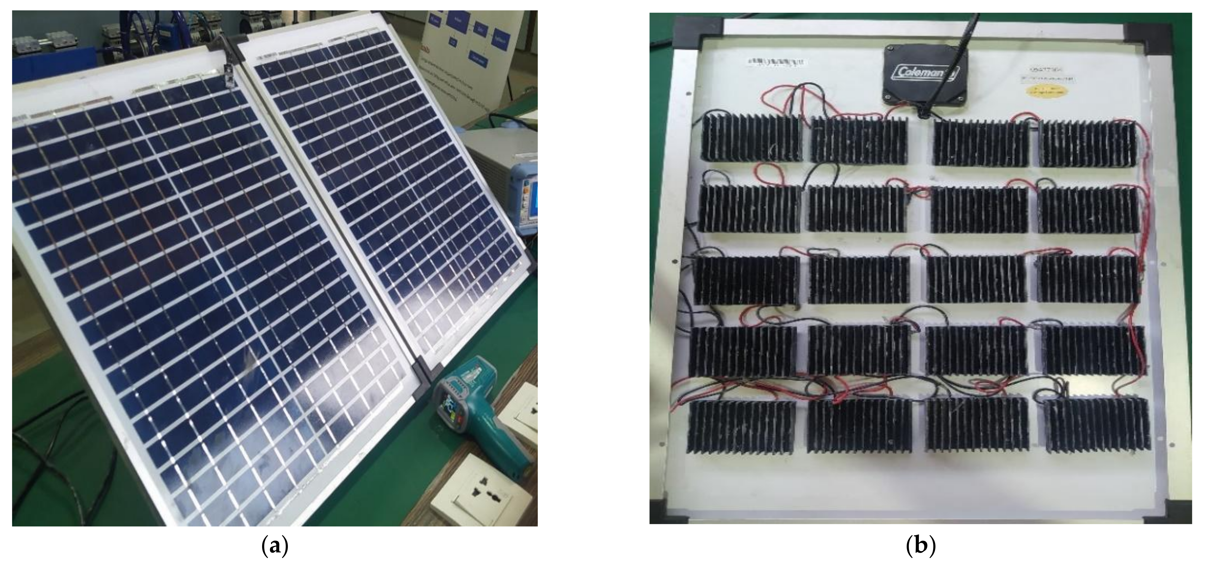
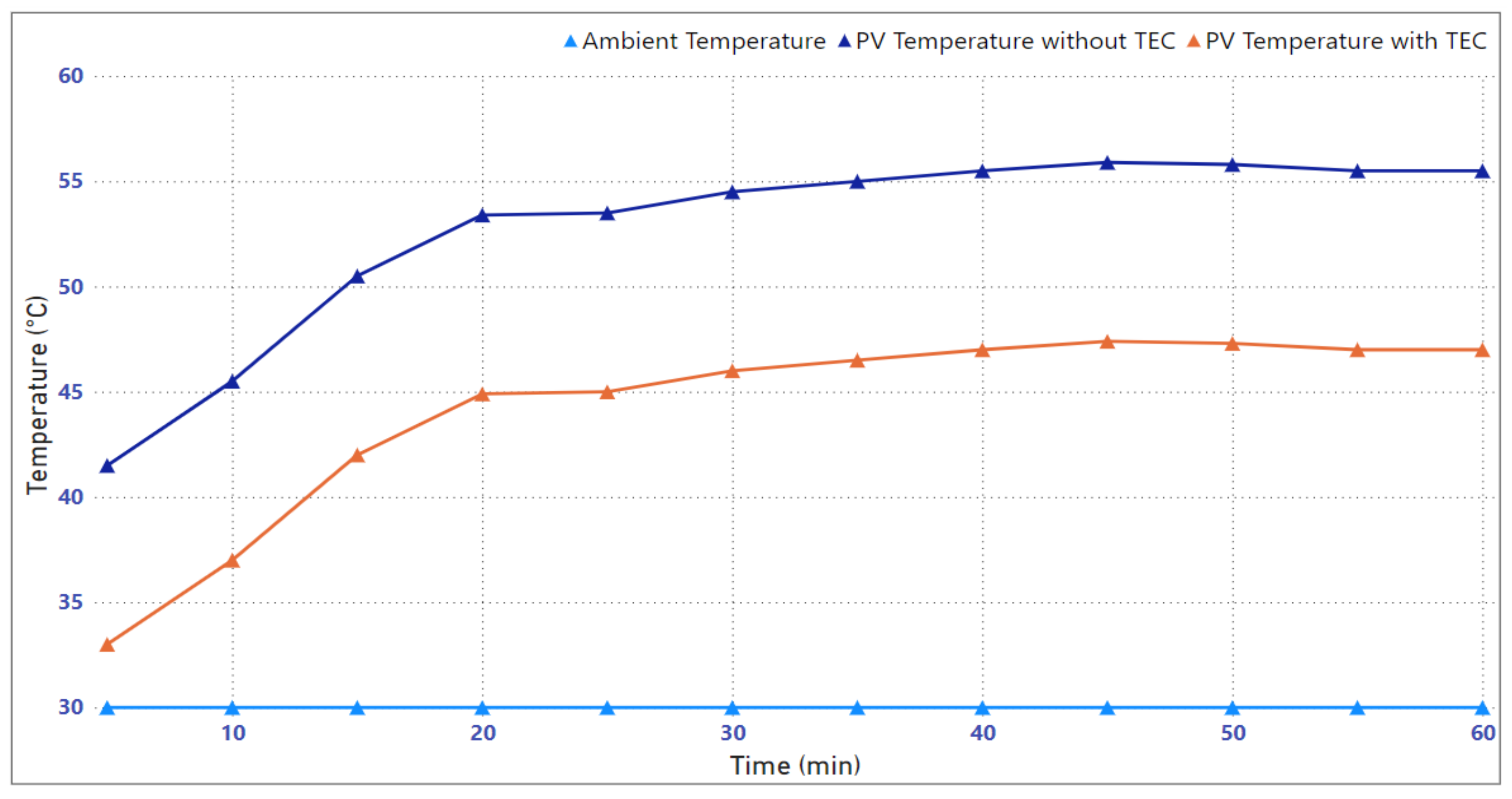
The indoor setup was utilized to check the effectiveness of the active cooling of the TECs in the proposed HSTEG system. For this purpose, a model was set up indoors under control conditions with the experiment lasting one hour. As depicted in Figure 12a, the experiment was performed using two solar panels: one solar panel has thermoelectric modules on its back while the other panel does not have any modules. The back of the solar panel with the TEMs and heat sinks is shown in Figure 12b. Voltage was provided to the modules to analyze their active cooling behavior in the controlled environment. The experiment aimed to maintain a controlled and consistent irradiance level throughout. By controlling the lighting conditions, variations in irradiance that could potentially influence the results were minimized. The panels were exposed to the incident solar radiation through the window. Stable humidity conditions ensured that any observed effects on the solar panels’ performance can be attributed to the specific variables being studied, rather than fluctuations in moisture content. The air pressure was assumed to be constant or within typical atmospheric levels in the controlled indoor environment. The indoor ambient temperature was set to 30 °C as depicted in Figure 13. It can be observed from Figure 13 that the temperature of the solar panels with the modules is low in comparison to the solar panel without the modules. The temperature of the panel was controlled using active cooling by providing voltage to the modules. Figure 14 shows a comparison of the two solar panels in terms of the power output. It can be observed that the power of the solar panel with the TECs was improved significantly in comparison with the solar panels without the TECs.

4.2. Outdoor Environment

In the outdoor environment, we set up an experiment to investigate the effects of active cooling as well as passive cooling on solar panel performance. The experiment spanned four hours between 11 a.m. and 3 p.m., during which two solar panels were utilized—one equipped with TEMs on its back and the other without TEMs. Our primary objective was to analyze the behavior of TEMs for cooling as well as power generation under natural environmental conditions. Figure 15 illustrates the experimental setup. We took into consideration the inherent environmental factors that influence solar panel performance. As outdoor conditions are subject to natural variations, we acknowledge that complete control over certain parameters, such as natural irradiance levels, humidity, and air pressure, was not possible. Instead, the experiment was designed to observe and analyze the behavior of solar panels equipped with TEMs under real-world outdoor conditions. The outdoor experiment allowed us to evaluate the practical viability of active and passive cooling techniques under real-world conditions, providing valuable insights for enhancing solar panel efficiency in outdoor applications. Different irradiance values were observed during the study to depict the behavior of the proposed system under varying conditions.

4.2.1. Active Cooling Mode

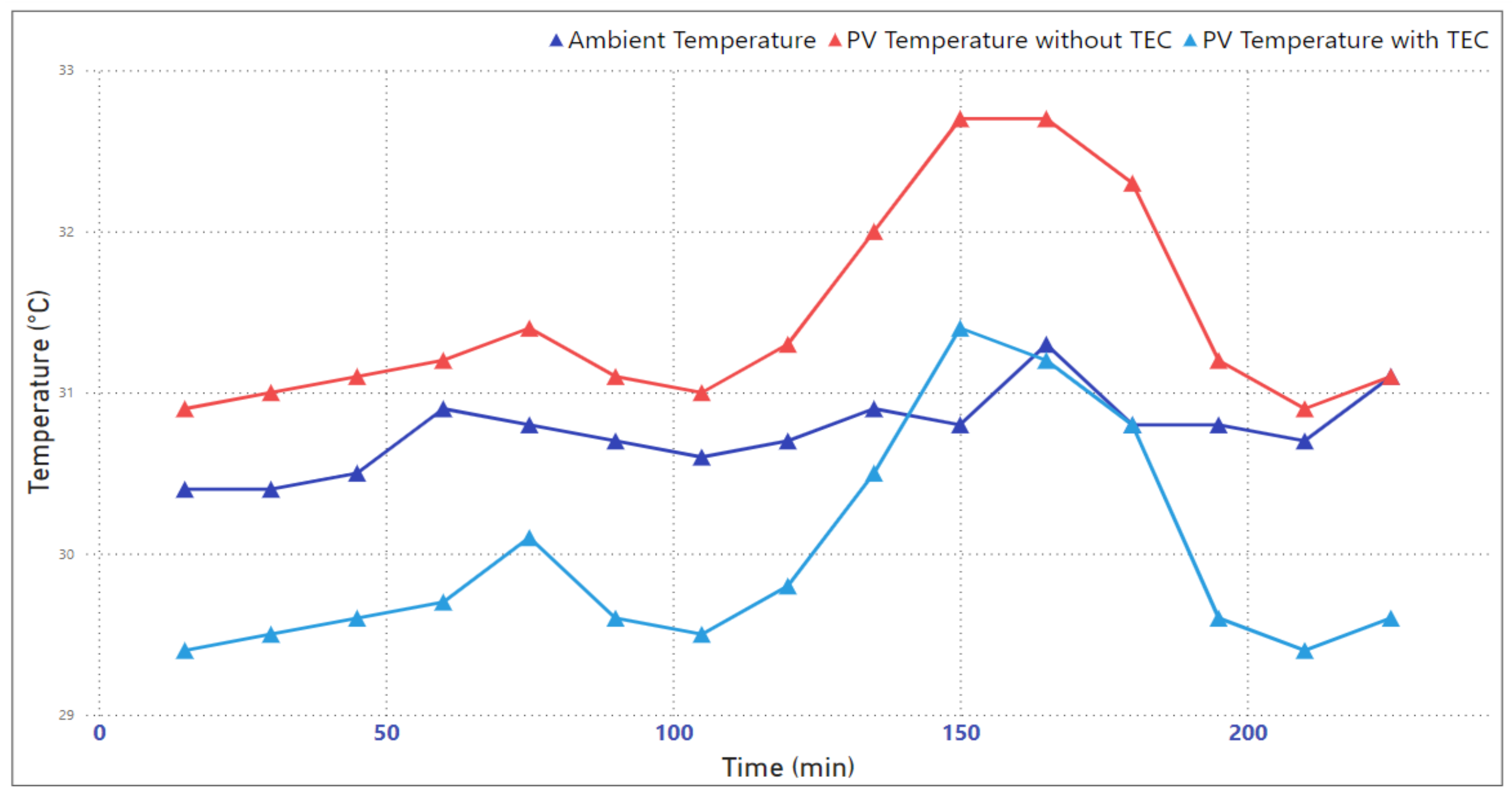
In the active cooling mode, power was supplied to the TEMs. Since the cold side is attached to the panel and the cooling effect is directly proportional to the applied voltage, the modules pump the heat from the cold side to the hot side and dissipate it to the environment using the heat sinks. This process prevents the PV panels from overheating by reducing their temperature, thus increasing the power output. Figure 16 shows the PV panel temperature with and without the TECs and depicts its effect on the temperature of the panel. It can be observed that the panel temperature is higher than the ambient temperature, causing it to overheat. The TECs reduce the temperature of the panel by the Peltier effect. It should be noted that, in real conditions, heat sinks cannot dissipate an infinite amount of power. Therefore, the modules do not behave exactly as observed in the simulation.
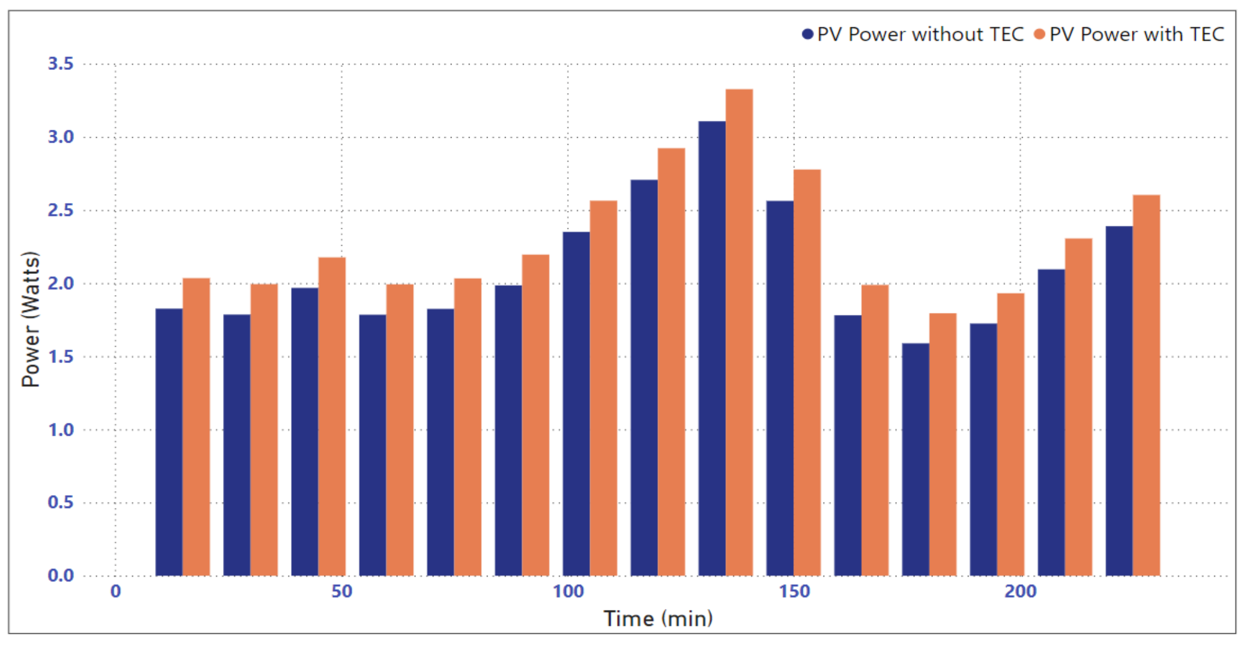
Figure 17 depicts the increase in output power due to a reduction in the temperature of the solar panel. It can be observed that at the start of the cooling process, the power with and without the TECs is almost the same, which is due to the fact the solar panel was not cooled enough at the beginning, so over time, as the temperature of the solar panel goes down because of the active cooling, a significant improvement is observed in the output power.
Table 2 shows the cooling effect of the TECs for enhancing the power output in a tabulated form. The ambient temperatures during the experiment ranged between 30.4 °C and 31.3 °C. Precise measurements of the PV arrays’ temperatures were recorded, with the non-cooled array registering temperatures between 30.9 °C and 32.7 °C, and the actively cooled array maintaining temperatures in the range of 29.4 °C to 32.5 °C. The data analysis indicated that the TECs were successful in reducing the operating temperature of the actively cooled PV array compared to the non-cooled array. Additionally, we closely monitored the power output of both PV arrays. Without the TECs, the power output ranged from 1.811 W to 3.107 W, while with the TECs, the power output experienced an increase, ranging from 1.812 W to 3.326 W. These results underscore the efficacy of active cooling using TECs in enhancing the efficiency of PV arrays, leading to higher levels of power generation even under varying ambient temperature conditions. The experiment demonstrates the potential benefits of implementing active cooling techniques for improving the overall performance and energy yield of solar PV systems in real-world outdoor environments. The efficiency of the PV and HSTEG systems was computed as follows [43,44]:
η = P o u t P i n × 100
where the input power is computed as P i n = E × A with E as the incident solar radiation in W/m2 and A as the module area in m2. Based on the average output power, a measured irradiance of 200 W/m2, and a module area of 0.1575 m2, the electrical efficiencies of the PV and HSTEG systems were computed as 6.60% and 7.23%, respectively. An average increase of 9.54% was observed in the efficiency of the cooled PV panels using the TECs. The results demonstrate the efficacy of TECs for the enhancement of PV panel efficiency through cooling.
It is pertinent to mention that the cooling effect of a TEC is directly proportional to the supplied power. Increasing the power supplied to the TEC will result in a rapid decrease in the temperature of the PV module, with an observable variance of up to 20 °C. Similarly, the efficacy of the TEC is also dependent on the ambient temperature. When the ambient temperature is low, like at 30 °C, supplying power to the TEC becomes unnecessary due to its minimal impact on the PV module, which is closer to the ideal solar panel temperature of 25 °C. Thus, using a temperature controller allows us to conserve the power intended for the TEC when the ambient temperature reaches higher levels, such as 55 °C.

4.2.2. Passive Cooling Mode

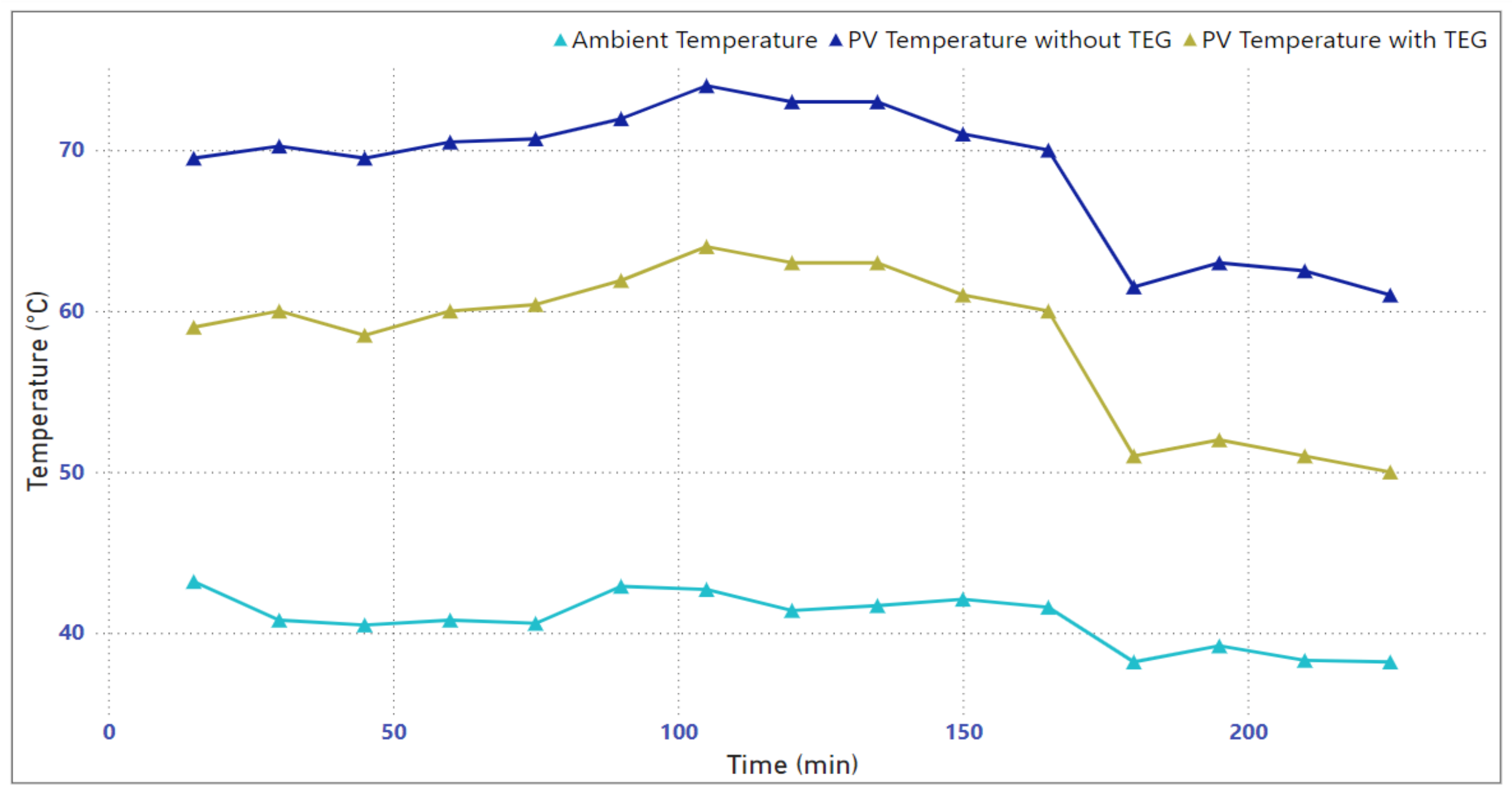
In passive cooling, the thermoelectric modules are not provided with any input power. The modules passively reduce the temperature of the panel through the heatsinks and use the temperature difference across it to generate additional power. Figure 18 shows the PV panel temperature with and without the modules and depicts the passive cooling of the modules. It can be observed that the attached modules decrease the temperature of the panel, ultimately helping to increase its output power.
Figure 19 depicts the combined effect of the modules in enhancing PV efficiency through cooling as well as the additional power generated by utilizing the temperature difference. It can be seen that the combined effect of cooling and generation significantly improves the power output of the panel. A substantial improvement was observed at the highest temperatures, because at higher temperatures, the difference between the ambient and panel temperatures is high, hence the modules have a considerable impact.
Table 3 shows the impact of TEGs on the performance of a PV array under varying ambient temperatures. It can be observed that the ambient temperatures during the experiment ranged from 38.2 °C to 43.2 °C. The PV array’s temperatures were measured both with and without TEGs, with the non-cooled array registering temperatures between 61 °C and 74 °C, and the module-cooled array maintaining lower temperatures, varying from 51 °C to 61.9 °C. The data revealed that the modules effectively reduced the PV array’s operating temperature, mitigating the temperature rise. Additionally, the power output of the PV array was measured under both conditions. Without the modules, the power output ranged from 10.5 W to 14.6 W, while with modules, the power output increased, ranging from 12.6 W to 16.7 W. These results demonstrate the positive impact of passive cooling with TEMs in enhancing the efficiency and power generation of PV arrays under high-temperature conditions. Meanwhile, the additional power generated by the TEGs from the waste heat significantly contributes towards this enhancement in efficiency. The efficiency of the PV and HSTEG systems was computed using Equation (18). Based on the average output power, measured irradiance of 800 W/m2, and module area of 0.1575 m2, the electrical efficiencies of the PV and HSTEG systems were computed as 10.58% and 12.22%, respectively. An average increase of 15.50% was observed in the efficiency of the HSTEG system. The results demonstrate the HSTEG system’s potential to significantly improve PV panel efficiency and energy generation, offering a promising avenue for advancing solar energy technology.
In this case, we employ heat sinks coupled with TEMs to maximize their effectiveness. From our analysis, it is evident that employing more efficient heat sinks would result in the enhanced performance of TEMs. Moreover, we delve into the outcomes of both active and passive cooling techniques below.

5. Conclusions

Solar energy, a cost-effective and abundant renewable resource, faces efficiency challenges due to elevated cell temperatures. This study proposes a hybrid solar thermoelectric generation (HSTEG) system, employing thermoelectric modules (TEMs) to act as coolers and power generators. Extensive MATLAB-Simulink analyses and experiments in indoor as well as outdoor environments validate this approach. The use of TECs for the active cooling of the PV system leads to an increase in its efficiency of 9.54%. Similarly, the passive cooling by TECs along with the additional power generated by the TEGs from the excessive heat led to an increase in the efficiency of the PV system of 15.50%. The maximum power output was also enhanced through the proposed system. These results underscore HSTEG’s potential to significantly elevate PV panel efficiency and energy output. As renewable energy gains traction, this innovative integration offers a path to sustainably optimize solar energy utilization.

Author Contributions

Conceptualization, M.A.B., Z.M.H. and M.O.K.; methodology, M.F., M.A.B., M.A. and M.A.M.; software, M.A.B., M.A.M. and Z.M.H.; validation, M.A., Z.M.H. and M.O.K.; formal analysis, M.A.B., M.A. and M.A.M.; investigation, M.F., M.A.B. and Z.M.H.; resources, M.A. and M.O.K.; data curation, M.F. and M.A.M.; writing—M.A.B. and Z.M.H.; writing—review and editing, M.F. and M.O.K.; visualization, M.A.B., Z.M.H. and M.O.K.; supervision, M.A.B. and M.O.K. All authors have read and agreed to the published version of the manuscript.

Funding

This research received no external funding.

Institutional Review Board Statement

Not applicable.

Informed Consent Statement

Not applicable.

Data Availability Statement

Data are contained within the article.

Acknowledgments

We are very grateful to the Office of Research, Innovation and Commercialization (ORIC), The Islamia University of Bahawalpur, Pakistan (No. 3900/ORIC/IUB/2021) for their support in this study.

Conflicts of Interest

The authors declare no conflicts of interest.

References

  1. Thoma, M. Electrical energy usage over the business cycle. Energy Econ. 2004, 26, 463–485. [Google Scholar] [CrossRef]
  2. Pérez-Lombard, L.; Ortiz, J.; Pout, C. A review on buildings energy consumption information. Energy Build. 2008, 40, 394–398. [Google Scholar] [CrossRef]
  3. Bose, B.K. Global warming: Energy, environmental pollution, and the impact of power electronics. IEEE Ind. Electron. Mag. 2010, 4, 6–17. [Google Scholar] [CrossRef]
  4. Owusu, P.A.; Asumadu-Sarkodie, S. A review of renewable energy sources, sustainability issues and climate change mitigation. Cogent Eng. 2016, 3, 1167990. [Google Scholar] [CrossRef]
  5. Weaver, P.; Jansen, L.; van Grootveld, G.; van Spiegel, E.; Vergragt, P. Sustainable Technology Development; Routledge: London, UK, 2017. [Google Scholar] [CrossRef]
  6. Lewis, N.S. Toward Cost-Effective Solar Energy Use. Science 2007, 315, 798–801. [Google Scholar] [CrossRef] [PubMed]
  7. Huang, S.; Xu, X. A regenerative concept for thermoelectric power generation. Appl. Energy 2017, 185, 119–125. [Google Scholar] [CrossRef]
  8. Kabir, E.; Kumar, P.; Kumar, S.; Adelodun, A.A.; Kim, K.-H. Solar energy: Potential and future prospects. Renew. Sustain. Energy Rev. 2018, 82, 894–900. [Google Scholar] [CrossRef]
  9. Sampaio, P.G.V.; González, M.O.A. Photovoltaic solar energy: Conceptual framework. Renew. Sustain. Energy Rev. 2017, 74, 590–601. [Google Scholar] [CrossRef]
  10. Tschopp, D.; Tian, Z.; Berberich, M.; Fan, J.; Perers, B.; Furbo, S. Large-scale solar thermal systems in leading countries: A review and comparative study of Denmark, China, Germany and Austria. Appl. Energy 2020, 270, 114997. [Google Scholar] [CrossRef]
  11. Mehmood, H.; Tauqeer, T.; Hussain, S. Recent progress in silicon-based solid-state solar cells. Int. J. Electron. 2018, 105, 1568–1582. [Google Scholar] [CrossRef]
  12. Green, M.A.; Emery, K.; Hishikawa, Y.; Warta, W.; Dunlop, E.D. Solar cell efficiency tables (Version 45). Prog. Photovolt. Res. Appl. 2015, 23, 1–9. [Google Scholar] [CrossRef]
  13. Munshi, A.H.; Kephart, J.M.; Abbas, A.; Shimpi, T.M.; Barth, K.L.; Walls, J.M.; Sampath, W.S. Polycrystalline CdTe photovoltaics with efficiency over 18% through improved absorber passivation and current collection. Sol. Energy Mater. Sol. Cells 2018, 176, 9–18. [Google Scholar] [CrossRef]
  14. Marion, B.; Adelstein, J.; Boyle, K.; Hayden, H.; Hammond, B.; Fletcher, T.; Canada, B.; Narang, D.; Kimber, A.; Mitchell, L.; et al. Performance parameters for grid-connected PV systems. In Proceedings of the Conference Record of the Thirty-First IEEE Photovoltaic Specialists Conference, Lake Buena Vista, FL, USA, 3–7 January 2005; pp. 1601–1606. [Google Scholar] [CrossRef]
  15. Gokhale, P.; Loganathan, B.; Crowe, J.; Date, A.; Date, A. Development of Flexible Thermoelectric Cells and Performance Investigation of Thermoelectric Materials for Power Generation. Energy Procedia 2017, 110, 281–285. [Google Scholar] [CrossRef]
  16. Alboteanu, I.L.; Ocoleanu, C.F.; Bulucea, C.A. Cooling System for Photovoltaic Module; University of Craiova: Craiova, Romania, 2012; ISBN 978-1-61804-110-4. [Google Scholar]
  17. Kim, J.; Rabelo, M.; Padi, S.P.; Yousuf, H.; Cho, E.C.; Yi, J. A review of the degradation of photovoltaic modules for life expectancy. Energies 2021, 14, 4278. [Google Scholar] [CrossRef]
  18. Yin, E.; Li, Q.; Xuan, Y. One-day performance evaluation of photovoltaic-thermoelectric hybrid system. Energy 2018, 143, 337–346. [Google Scholar] [CrossRef]
  19. Siecker, J.; Kusakana, K.; Numbi, E.B. A review of solar photovoltaic systems cooling technologies. Renew. Sustain. Energy Rev. 2017, 79, 192–203. [Google Scholar] [CrossRef]
  20. Salem Ahmed, M.; Mohamed AS, A.; Maghrabie, H.M. Performance evaluation of combined photovoltaic thermal water-cooling system for hot climate regions. J. Sol. Energy Eng. 2019, 141, 041010. [Google Scholar] [CrossRef]
  21. Khamooshi, M.; Salati, H.; Egelioglu, F.; Hooshyar Faghiri, A.; Tarabishi, J.; Babadi, S. A review of solar photovoltaic concentrators. Int. J. Photoenergy 2014, 2014, 958521. [Google Scholar] [CrossRef]
  22. Maghrabie, H.; Mohamed, A.; Fahmy, A.; Abdel Samee, A.A. Performance augmentation of PV panels using phase change material cooling technique: A review. SVU-Int. J. Eng. Sci. Appl. 2021, 2, 1–13. [Google Scholar] [CrossRef]
  23. Nižetić, S.; Čoko, D.; Yadav, A.; Grubišić-Čabo, F. Water spray cooling technique applied on a photovoltaic panel: The performance response. Energy Convers. Manag. 2016, 108, 287–296. [Google Scholar] [CrossRef]
  24. Sheik, M.S.; Kakati, P.; Dandotiya, D.; Ramesh, C.S. A comprehensive review on various cooling techniques to decrease an operating temperature of solar photovoltaic panels. Energy Nexus 2022, 8, 100161. [Google Scholar] [CrossRef]
  25. Biwole, P.H.; Eclache, P.; Kuznik, F. Phase-change materials to improve solar panel’s performance. Energy Build. 2013, 62, 59–67. [Google Scholar] [CrossRef]
  26. Shoeibi, S.; Kargarsharifabad, H.; Sadi, M.; Arabkoohsar, A.; Mirjalily, S.A.A. A review on using thermoelectric cooling, heating, and electricity generators in solar energy applications. Sustain. Energy Technol. Assess. 2022, 52, 102105. [Google Scholar] [CrossRef]
  27. Uchida, K.-I.; Adachi, H.; Kikkawa, T.; Kirihara, A.; Ishida, M.; Yorozu, S.; Maekawa, S.; Saitoh, E. Thermoelectric Generation Based on Spin Seebeck Effects. Proc. IEEE 2016, 104, 1946–1973. [Google Scholar] [CrossRef]
  28. Gorai, P.; Stevanović, V.; Toberer, E.S. Computationally guided discovery of thermoelectric materials. Nat. Rev. Mater. 2017, 2, 17053. [Google Scholar] [CrossRef]
  29. Contento, G.; Lorenzi, B.; Rizzo, A.; Narducci, D. Efficiency enhancement of a-Si and CZTS solar cells using different thermoelectric hybridization strategies. Energy 2017, 131, 230–238. [Google Scholar] [CrossRef]
  30. Lin, J.; Liao, T.; Lin, B. Performance analysis and load matching of a photovoltaic–thermoelectric hybrid system. Energy Convers. Manag. 2015, 105, 891–899. [Google Scholar] [CrossRef]
  31. Lorenzi, B.; Chen, G. Theoretical efficiency of hybrid solar thermoelectric-photovoltaic generators. J. Appl. Phys. 2018, 124, 024501. [Google Scholar] [CrossRef]
  32. Alahmer, A.; Khalid, M.B.; Beithou, N.; Borowski, G.; Alsaqoor, S.; Alhendi, H. An Experimental Investigation into Improving the Performance of Thermoelectric Generators. J. Ecol. Eng. 2022, 23, 100–108. [Google Scholar] [CrossRef]
  33. Van Sark, W.G.J.H.M. Feasibility of photovoltaic–thermoelectric hybrid modules. Appl. Energy 2011, 88, 2785–2790. [Google Scholar] [CrossRef]
  34. Fisac, M.; Villasevil, F.X.; López, A.M. High-efficiency photovoltaic technology including thermoelectric generation. J. Power Sources 2014, 252, 264–269. [Google Scholar] [CrossRef]
  35. Malik, M.S.; Azmatullah, U.; Khan, M.O.; Abu Bakr, M.; Ahmad, M. Analysis of Energy Management and Battery Sizing in an Off-Grid Hybrid Solar Thermoelectric Generation System. Energy Technol. 2022, 10, 2100732. [Google Scholar] [CrossRef]
  36. Shatar, N.M.; Rahman, M.A.A.A.; Salim, S.A.Z.S.; Ariff, M.H.M.; Muhtazaruddin, M.N.; Badlisah, A.K.A. Design of Photovoltaic-Thermoelectric Generator (PV-TEG) Hybrid System for Precision Agriculture. In Proceedings of the 2018 IEEE 7th International Conference on Power and Energy (PECon), Kuala Lumpur, Malaysia, 3–4 December 2018; pp. 50–55. [Google Scholar] [CrossRef]
  37. Utomo, B.R.; Sulistyanto, A.; Riyadi, T.W.B.; Wijayanta, A.T. Enhanced Performance of Combined Photovoltaic–Thermoelectric Generator and Heat Sink Panels with a Dual-Axis Tracking System. Energies 2023, 16, 2658. [Google Scholar] [CrossRef]
  38. Riyadi, T.W.B.; Soumi, A.I.; Haryanto; Hendrawan, A. Performance Assessment of a Photovoltaic Cell Coupled with a Thermoelectric Generator. Eng. Proc. 2024, 63, 23. [Google Scholar] [CrossRef]
  39. Maryani, S.; Kusumanto, R.D.; Carlos, R.S. Solar Panel Optimization Using Peltier Module TEC1-12706. J. Mech. Civ. Ind. Eng. 2023, 4, 43–50. [Google Scholar] [CrossRef]
  40. Zhang, X.; Zhao, L.-D. Thermoelectric materials: Energy conversion between heat and electricity. J. Mater. 2015, 1, 92–105. [Google Scholar] [CrossRef]
  41. Yilmaz, U.; Cavus, T.; İslamoğlu, Y. Bidirectional Modeling of Thermoelectric Module Using MATLAB/Simulink for Circuit Simulations. IEEE Access 2022, 10, 82680–82696. [Google Scholar] [CrossRef]
  42. Hasan, M.H.; Toh, K.C. Optimization of a Thermoelectric Cooler-Heat Sink Combination for Active Processor Cooling. In Proceedings of the 2007 9th Electronics Packaging Technology Conference, Singapore, 10–12 December 2007; pp. 848–857. [Google Scholar] [CrossRef]
  43. Hammad, W.; Sweidan TE, O.; Abuashour, M.I.; Khalid, H.M.; Muyeen, S.M. Thermal management of grid-tied PV system: A novel active and passive cooling design-based approach. IET Renew. Power Gener. 2021, 15, 2715–2725. [Google Scholar] [CrossRef]
  44. Patil, T.G.; Asokan, S. Comparative analysis of calculation of solar panel efficiency degradation. In Proceedings of the 2017 Third International Conference on Science Technology Engineering & Management (ICONSTEM), Chennai, India, 23–24 March 2017; pp. 522–525. [Google Scholar] [CrossRef]
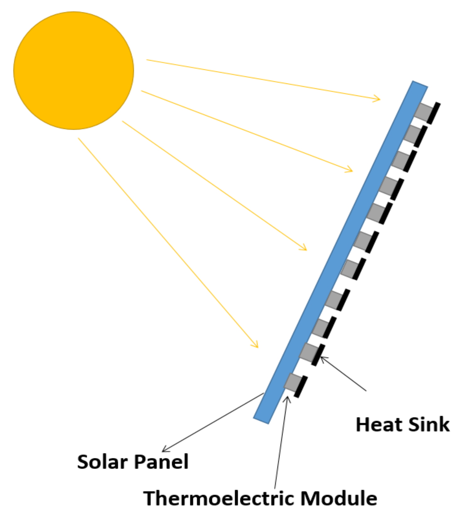
Figure 1. Model of hybrid solar thermoelectric system and heat transfer mechanism.
Energies 17 02590 g001
Figure 2. Solar panel simulation.
Energies 17 02590 g002
Figure 3. Effect of temperature on the output of solar panel.
Energies 17 02590 g003
Figure 4. Thermoelectric cooler simulation.
Energies 17 02590 g004
Figure 5. Effect of input voltage on the cooling of TEC.
Energies 17 02590 g005
Figure 6. Thermoelectric generator simulation.
Energies 17 02590 g006
Figure 7. Effect of temperature difference on the output power of TEG.
Energies 17 02590 g007
Figure 8. Combined solar panel and TEG simulation.
Energies 17 02590 g008
Figure 9. Effect of TEG on the output of solar panel.
Energies 17 02590 g009
Figure 10. Combined solar panel and TEC simulation.
Energies 17 02590 g010
Figure 11. Effect of TEC on the solar panel output power.
Energies 17 02590 g011
Figure 12. (a) indoor setup of hybrid solar thermoelectric generation system. (b) The back of the solar panel with TEMs and heat sinks attached.
Energies 17 02590 g012
Figure 13. Effect of TECs on the temperature of the solar panel under control conditions.
Energies 17 02590 g013
Figure 14. Effect of TECs on the power of the solar panel under control conditions.
Energies 17 02590 g014
Figure 15. Outdoor setup of the proposed HSTEG system.
Energies 17 02590 g015
Figure 16. Effect of TECs on the solar panel temperature in the open environment.
Energies 17 02590 g016
Figure 17. Effect of TECs on the solar panel output power in the open environment.
Energies 17 02590 g017
Figure 18. Effect of TEGs on the solar panel temperature in the open environment.
Energies 17 02590 g018
Figure 19. Effect of TEGs on the solar panel output power in the open environment.
Energies 17 02590 g019
Table 1. Specifications of elements used in experimental setup.
S. No.ItemDescriptionQuantity
1Solar PanelPower: 15 W2
2Thermoelectric ModulesModel: TEC-12706
Current: 6A
20
3Thermoelectric PasteConductivity: 4.2 W/m210
4Heat SinksAluminum Heat Sinks20
5Light SensorBH1750—Light Intensity Sensor Module1
6Temperature SensorLM352
7Arduino MegaATmega25601
8Temperature GunDigital Laser Infrared 1
Table 2. Effect of TEC on solar panel output.
S. No.Ambient Temp. (°C)PV Temp. without TEC (°C)PV Temp. with TEC (°C)PV Power without TEC (W)PV Power with TEC (W)
130.432.532.51.8111.812
230.430.929.41.8262.034
330.43129.51.7851.993
430.531.129.61.9672.176
530.931.229.71.7841.992
630.831.430.11.8242.032
730.731.129.61.9852.195
830.63129.52.3502.564
930.731.329.82.7062.922
1030.93230.53.1073.326
1130.832.731.42.5622.777
1231.332.731.21.7801.988
1330.832.330.81.5881.794
1430.831.229.61.7241.931
1530.730.929.42.0942.305
1631.131.129.62.3892.603
Table 3. Effect of TEG on solar panel output.
S. No.Ambient Temp. (°C)PV Temp. without TEG (°C)PV Temp. with TEG (°C)PV Power without TEG (W)PV Power with TEG (W)TEG Power (mW)Net Power (W)
143.269.55914.07116.12653.116.179
240.870.256014.51816.59154.7416.645
340.569.558.514.66016.74448.9616.793
440.870.56014.44316.51551.2316.566
540.670.760.414.29816.36443.7316.408
642.971.9561.914.11716.17342.0216.215
742.7746413.96516.01146.5516.057
841.4736314.55216.62743.216.670
941.7736313.85015.89149.4115.940
1042.1716113.88615.92847.0115.975
1141.6706013.97516.02142.3316.063
1238.261.55111.11313.20636.7213.242
1339.2635210.54512.635.2812.635
1438.362.55110.85412.93232.3412.964
1538.2615010.54512.632.3412.632
1643.269.55914.07116.12653.116.179
Disclaimer/Publisher’s Note: The statements, opinions and data contained in all publications are solely those of the individual author(s) and contributor(s) and not of MDPI and/or the editor(s). MDPI and/or the editor(s) disclaim responsibility for any injury to people or property resulting from any ideas, methods, instructions or products referred to in the content.