Article

Design and Performance Evaluation of a Hybrid Active Power Filter Controller

Faculty of Electrical Engineering, University of Ljubljana, 1000 Ljubljana, Slovenia
*
Author to whom correspondence should be addressed.
Energies 2024, 17(11), 2492; https://doi.org/10.3390/en17112492
Submission received: 30 April 2024 / Revised: 15 May 2024 / Accepted: 20 May 2024 / Published: 22 May 2024
(This article belongs to the Special Issue Power Electronics and Power Quality 2024)

Abstract

:
This paper introduces a novel hybrid filter topology that combines passive and active components to enhance harmonic filtering and resonance damping in electrical power systems. The design integrates a three-phase two-level voltage-source converter with a double-tuned passive filter in parallel, significantly reducing the power rating and operational costs while maintaining good harmonic filtering performance and reactive current compensation. Double-tuned passive filters, compared to single-tuned ones, offer improved harmonic attenuation at multiple frequencies, enhancing overall system efficiency. Moreover, when used with the proposed hybrid filter topology, the double-tuned version allows for even lower dimensions of the active part, thereby further reducing system cost. A state-feedback controller is designed to enhance the performance of the hybrid filter, proving particularly effective in environments with complex impedance conditions. This paper also examines the impact of variations in passive component parameters, demonstrating the design’s robustness against potential deviations expected over the operational lifespan. The results indicate that the hybrid filter effectively mitigates harmonics and maintains operational stability under various transient conditions, as confirmed by analytical and simulation studies on a real industrial network model. These findings underline the hybrid filter’s potential to significantly improve power quality in modern electrical networks.

1. Introduction

The electrical power system (EPS) is currently facing significant changes, largely driven by the massive integration of distributed energy resources (DER), heat pumps (HP), and an anticipated large-scale transition of the transportation sector to electric vehicles (EVs). This increase in the number of modern loads, many of which connect to the EPS through power electronic converters, presents substantial challenges not only in terms of planning and operating the EPS efficiently but also in maintaining adequate power quality (PQ) parameters. Power quality issues, particularly harmonic distortion, converter-driven instability, and harmonic instability, have become more pronounced with the widespread adoption of power electronic-interfaced equipment. As industrial processes and everyday technologies become more sophisticated, ensuring a high power quality is no longer just a preference but a critical necessity [1,2,3,4,5].
Traditionally, maintaining appropriate levels of harmonic distortions in power systems has relied heavily on passive filters. These conventional solutions are known for their simplicity and cost-effectiveness in filtering out harmonics. However, passive filters have several disadvantages; they are typically designed for specific operating conditions and lack the flexibility to adapt to dynamic changes in the network. This can lead to issues such as resonance and over- or under-compensation, potentially worsening power quality issues instead of improving them [6,7,8]. On the other hand, active (converter-based) power devices offer more precise control over a wide range of frequencies and can adapt to changing conditions but come at a higher cost and complexity [9,10].
In this context, hybrid filters have emerged as a promising solution, combining the advantages of both passive and active filters while mitigating their respective limitations. The synergy between the passive components’ cost-effectiveness and the active components’ flexibility allows for more effective and efficient harmonic mitigation and reactive power compensation across varying conditions [11,12,13,14,15,16,17,18]. For example, the authors in [11,12] proposed hybrid filter topologies combining passive and active elements, demonstrating improved performance in harmonic filtering and resonance damping. However, these solutions require high ratings for the active components, which increases the costs and complexity.
There is an extensive literature on the potential of hybrid filters, highlighting various configurations and control strategies which exploit the benefits of integrated solutions. In [12,13], the authors proposed a series connection of the active inverter with the passive filter. They reported good filtering performance of the proposed topology; however, with the series connection of both active and passive parts, the inverter’s required current rating remains high, as the full fundamental frequency current flows through the inverter. In other cases, such as in papers [14,19], authors propose parallel combinations of both parts, which require the full voltage ratings of the inverter. Other authors also report some disadvantages of hybrid filters. Paper [20] presents a hybrid system aiming to reduce point-of-common-coupling (PCC) voltage total harmonic distortion (THD); however, a significant limitation noted was the complexity of the control system needed to effectively manage the hybrid filter. In [21], the authors addressed damping harmonic resonance with hybrid filters in industrial settings, noting that customization for specific industrial applications can add complexity to the integration process. In recent studies, for example [22], authors discuss a new topology of hybrid active power filters that integrates passive LC single-tuned circuits to reduce the overall system ratings. Their paper focuses on parameter design and might lack testing data to validate the theoretical improvements in stability and ratings’ reduction. In [23], the negative impact of DC-side voltage fluctuations on the system and their effect on experimental results are discussed. The above paper highlights that controlling the DC-side voltage is crucial to enhancing the performance of hybrid filters. Our paper addresses this issue by proposing a robust control strategy for the DC-side voltage, ensuring stability, and enhancing harmonic elimination. Through simulations, we demonstrate that our approach effectively manages DC-side voltage fluctuations.
The primary goal of this paper is to introduce an improved topology that combines the advantages of passive and active components to achieve effective harmonic filtering, resonance damping, and reactive power compensation at a significantly lower cost than that of fully active systems or other hybrid filter configurations. The proposed hybrid filter involves a parallel connection of a three-phase two-level voltage-source converter (VSC) with the circuit of a double-tuned passive filter (DTPF). The analytical and simulation results show that the power rating of the active part of the hybrid filter is only around 2% of the load rating. This substantially reduces the size and (operational) cost compared to traditional setups, with dimensions up to four times smaller than those required in a series hybrid filter configuration and at least forty times smaller than a standalone active filter [24]. A brief analysis of the hybrid filter’s dimensions is presented in this paper, with a more detailed analysis available in [25].
The second contribution of this paper is the development of a state-feedback controller, designed to enhance the performance of the proposed hybrid filter, especially in systems with complex impedance conditions, such as those in industrial environments with harmonic resonances. The control strategies for hybrid filters traditionally use wideband approaches, with proportional control being the most common approach [26,27,28,29,30,31]. However, the high proportional constants needed for effective filtering tend to compromise transient performance with the proposed topology [25]. Additionally, the poor dynamic behavior of this topology under fluctuating loads has been documented in [32], where a proportional–integral (PI) regulator implemented in the harmonic reference frame (HRF) was used to control the active part of the hybrid filter. Other authors have analyzed various control techniques such as sliding-mode control [28] and fuzzy neural network control [29], which enable the precise tracking of reference signals. However, these techniques increase the system’s order and complexity, making the application of such advanced control methods more challenging. Therefore, in this paper, a state-feedback controller in HRF is proposed, tailored for each harmonic frequency, offering an effective and stable control approach. The use of a state-feedback controller offers several advantages over conventional PI or proportional–resonant (PR) controllers. Firstly, since it is based on the system model, it provides accurate control and makes real-time adjustments based on system states (voltages and currents), ensuring a good dynamic response to system changes. Secondly, the state-feedback approach utilizes all available information about the system’s current state, not just error signals. Furthermore, state-feedback controllers are highly customizable and can be tuned to address specific system characteristics, such as resonance frequencies, when used with hybrid filters.
Through detailed analyses and simulations on a real industrial network model, this paper validates the theoretical benefits of the proposed hybrid filter. The results are expected to aid in the development of a more robust cost-effective solution for reactive power compensation, harmonic mitigation, and resonance damping, thereby supporting the sustainable development of modern power systems.
The novel contributions of this paper are the following:
Hybrid filter topology: We developed a novel hybrid filter topology that integrates double-tuned passive filters with a three-phase two-level voltage-source converter in a parallel connection. This design significantly reduces the power rating required for the active components, lowering the operational costs and physical dimensions compared to traditional hybrid and standalone filters. Unlike previous designs, our approach offers a cost-effective solution with enhanced harmonic attenuation.
Enhanced filtering performance: The double-tuned passive filter provides superior harmonic attenuation across a wider range of frequencies, making it more effective than previous designs.
State-feedback controller: A state-feedback controller tailored for each harmonic frequency is introduced, ensuring accurate control and real-time adjustments based on the system’s state. This approach improves the stability and filtering performance compared to conventional wideband control strategies like the PI or PR controllers used in existing hybrid filters.
Robustness to parameter variations: Our analysis demonstrates the design’s robustness against variations in passive component parameters, highlighting the reliability and practicality of the hybrid filter in real-world applications, a critical aspect often overlooked in previous research.
The structure of this paper is as follows. Section 2 introduces the proposed topology of the hybrid filter, explaining the configuration and benefits. Section 3 details the design of the state-feedback controller, including its mathematical model and implementation. Section 4 analyzes the filtering characteristics through mathematical models and simulation results. Section 5 assesses the hybrid filter’s performance under various conditions, including steady-state and transient responses, and explores the impact of passive filter parameter variations on the performance of the system. Finally, Section 6 concludes with a summary of the findings, the implications for filter design and operation, and future research directions.

2. Hybrid Filter Parallel Topology

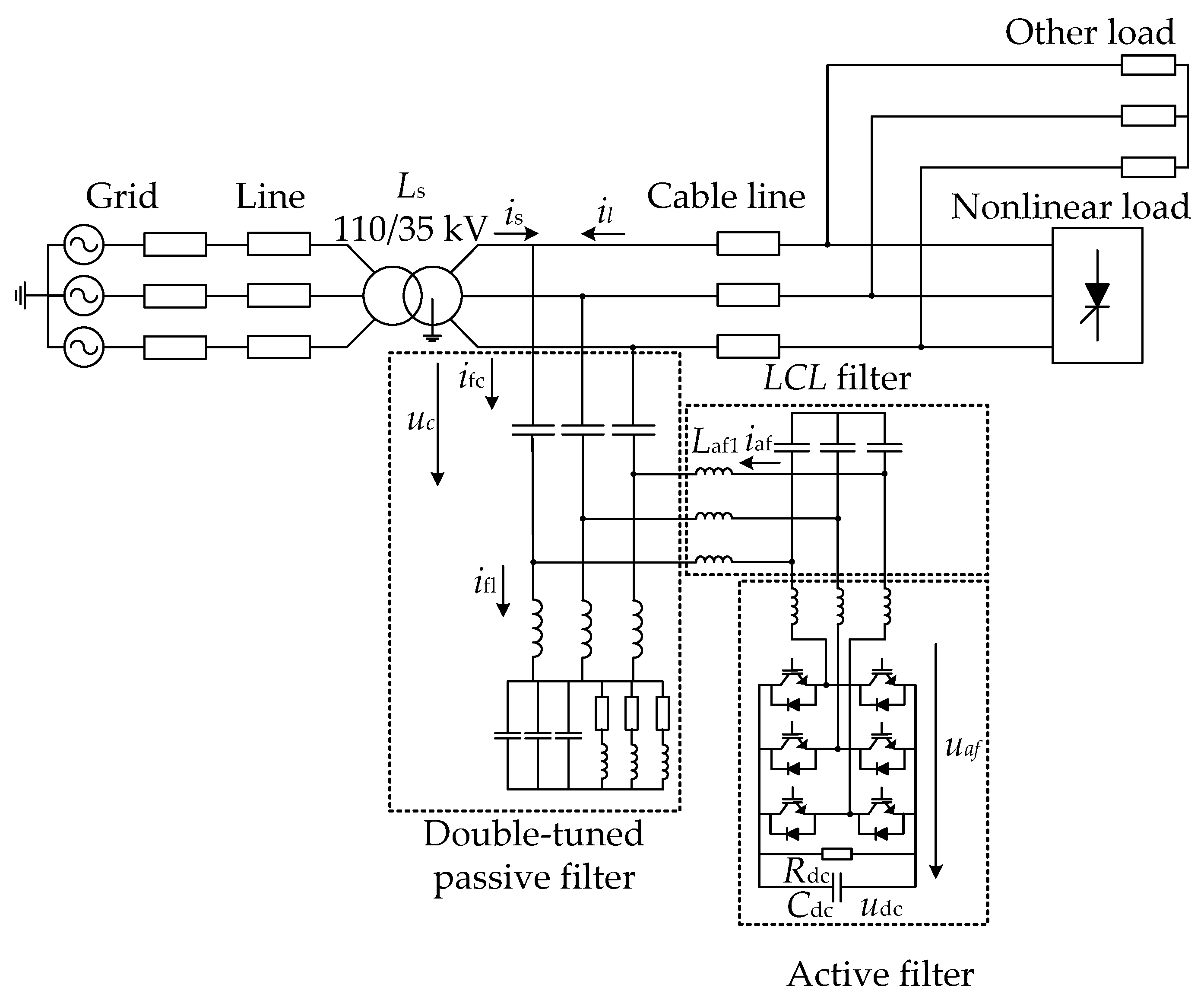
Figure 1 shows the proposed topology of the hybrid filter along with a nonlinear load, a supply transformer, and a network represented with an equivalent model. The hybrid filter comprises a three-phase two-level voltage converter, connected in parallel to the circuit of the double-tuned passive part. The system voltage is denoted by us, with Rs and Ls representing the system impedance. The nonlinear load, which generates harmonic currents (ilh), is connected to the network and depicted on the right side of the diagram.
The double-tuned passive filter is designed to mitigate specific harmonic frequencies more effectively than single-tuned filters. It includes primary tuning components such as the capacitor (Cpf), the inductor (Lpf), and the resistor (Rpf). Additionally, secondary tuning components (Cpf2 and Lpf2) enable the filter to target multiple harmonics, thereby providing better attenuation across a wider range of harmonic frequencies. The double-tuned topology has been chosen because it offers enhanced performance in filtering out harmonics, particularly those at the fifth and seventh orders, which are common in power systems with nonlinear loads.
Parallel to the passive filter is the active filter, which is configured using a two-level inverter. The choice of a two-level inverter is due to its simplicity, cost-effectiveness, and ease of control compared to multi-level inverters.
The active filter includes an LCL filter at its output, consisting of coupling inductors (Laf1 and Laf2), and a coupling capacitor (Caf). The LCL filter is used because it provides a superior filtering performance and better attenuation of the high-frequency switching harmonics generated by the inverter. The LCL filter also helps in reducing the overall ratings and power losses.
The DC side of the inverter is modeled with a DC-link capacitor (Cdc) and a resistor (Rdc) that represents the DC-side losses. The DC-link capacitor is crucial as it maintains a stable DC voltage level, which is necessary for the proper operation of the inverter.
The main advantage of this topology is that, due to the voltage drop across the capacitor Cpf of the passive filter, the voltage on the converter is relatively small (in the order of a few percent of the nominal supply voltage). Additionally, the fundamental component of the current through the converter is small due to the parallel circuit. This results in a reduced size and power rating for the active filter. Subsequently, the dimensions of the active part of the filter of the proposed topology will be analyzed. As it will be evident, the dimensions of the proposed topology are in the order of a few percent of the power of the compensated load.
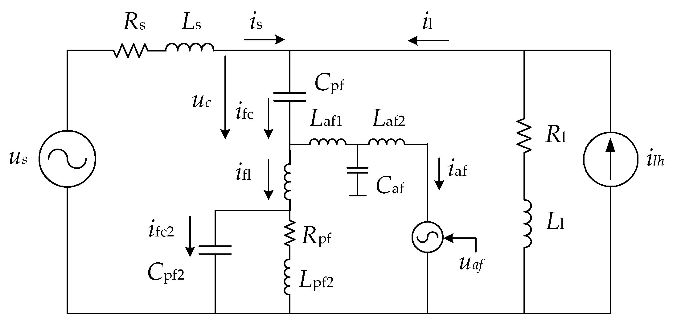
Figure 2 shows a single-line circuit of the proposed topology. It provides a simplified representation of the three-phase system, depicting all three phases with a single conductor line. This illustration facilitates the clear and straightforward visualization of the component connections and interactions within the hybrid filter without the complexity of a full three-phase layout. The symbols used are as follows: system voltage is denoted by us, and Rs and Ls constitute the system impedance. The harmonic current of the nonlinear load is represented by ilh. The load impedance is characterized by Rl and Ll. Cpf, Lpf, Rpf, Cpf2, and Lpf2 are the elements of the double-tuned passive filter. Laf1, Laf2, and Caf are the coupling impedances of the active filter (LCL filter). The converter output voltage is represented by an ideal voltage source, uaf.

Required Ratings of the Active Part

The analysis of the voltage and current dimensions of the proposed filter topology for the use of a single-tuned passive filter was presented in [25]. Below, we summarize the key equations of the rating analysis when using the topology proposed in this paper. Some of these equations will be needed later for deriving the controller for the active part.
The active filter must provide a small component of base voltage at the point of common coupling (PCC) to divert the base active current to flow in the parallel circuit. This voltage is equal to the voltage drop on the parallel circuit for a pure double-tuned passive filter, and it depends on the tuning frequencies of the passive part. It can be expressed as follows:
u a f , 1 = u s , 1 1 1 f t 1 f 1 2 + 1 1 f t 2 f 1 2
Here, f1 is the fundamental frequency (i.e., 50 Hz), and ft1 and ft1 are the tuned frequencies of the passive filter.
The harmonic voltage across the active part of the hybrid filter is equal to
u a f h = u s h + i i l h X C h ,
where the subscript h denotes the harmonic order, uafh represents the voltage across the active part of the hybrid filter at harmonic order h, ush is the source voltage at harmonic order h, ilh is the load current at harmonic order h, XCh is the reactance of the passive filter capacitor at harmonic order h, and i represents the imaginary unit.
The current flowing in the active part is given by the following:
i a f h = u s h i f t 2 f h f 1 X C 1 + i l h ( 1 f t 2 f h 2 )
where fh is the frequency of the corresponding harmonic, and iafh is the active filter current at harmonic order h.
The power ratings are given by (4).
S a f = U a f I a f
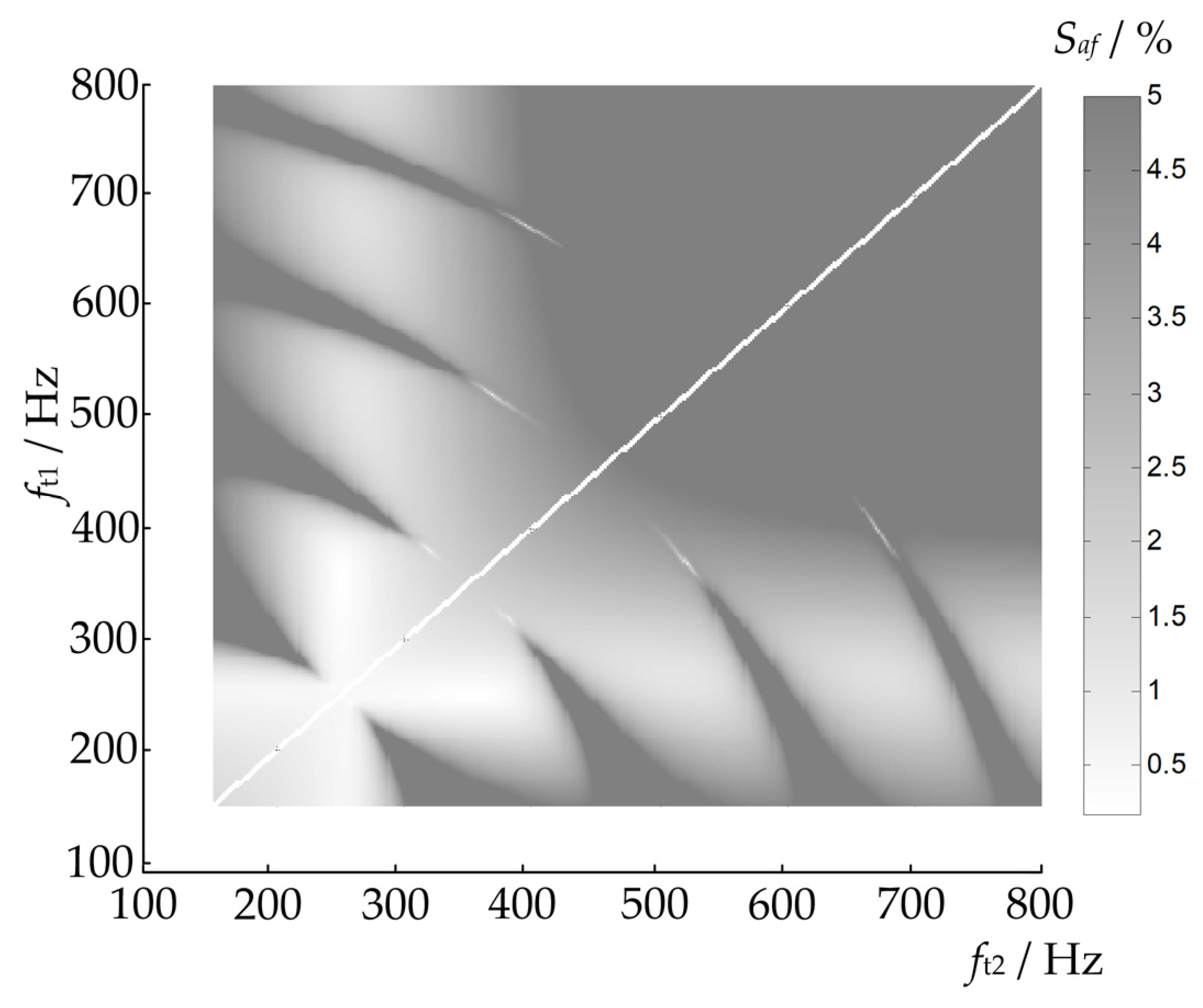
Figure 3 shows the required dimensions of the active part of the hybrid filter for various tuning frequencies of the passive part. As it can be seen from the figure, the dimensions of the active part are strongly dependent on the tuning frequency of the passive part or the combinations of tunings and have the lowest values (around 0.5%) when both stages of the passive part of the filter are tuned close to the harmonics present in the network (in this case, the fifth and seventh harmonics).
The figure above presents a heatmap where the x-axis represents the tuning frequency ft2 of the second stage of the passive filter, and the y-axis represents the tuning frequency ft1 of the first stage. The color gradient indicates the required power rating of the active filter Saf as a percentage of the total system power. The white diagonal line indicates points where ft1 = ft2, which are not practical since the filter stages should be tuned to different frequencies to target different harmonics effectively.
When the passive filter stages are tuned close to the prominent harmonic frequencies in the network, such as the fifth (250 Hz) and seventh (350 Hz) harmonics, the active filter’s power rating is minimized. This is because the passive filter stages effectively attenuate these harmonics, reducing the burden on the active filter. Consequently, the active filter mainly compensates for any residual harmonics, allowing it to operate with smaller dimensions and lower power ratings.
As the tuning frequencies of the passive filter deviate from these optimal points, the passive filter’s effectiveness in harmonic attenuation is lower. This increases the harmonic content that the active filter must compensate for, thereby increasing its required dimensions and power rating. The heatmap shows that the active filter’s power rating increases significantly as the tuning frequencies move away from the optimal points, illustrating the importance of the proper tuning of the passive stages.
It can also be observed that the theoretically lowest dimensions are even below 0.5%, which was the smallest dimension for a singly tuned filter as previously noted in [25]. Namely, as established in [25], in the case of a single-tuned passive filter, the dimensions of the necessary active part are largely conditioned by the tuning of the passive part and increase significantly as they deviate from the optimal tuning. By using a double-tuned filter, this problem is largely mitigated. There are several suitable tuning combinations where the dimensions of the active part of the filter remain low (e.g., <2%).

3. Control Algorithm Design

To improve the filtering characteristics of the proposed filter and ensure a stable operation, the linear–quadratic (LQ) regulator in state space is presented, which will be derived in the dq0-coordinate system based on the mathematical models from Section 3.1 and Section 3.2. The LQ regulator will be derived for symmetric voltage and current conditions. In addition to the basic current regulation loop which allows the tracking of reference values, the regulation of the DC voltage will also be presented in more detail, and the control branch of the regulator will be described, which will function to limit the current through the voltage converter. The controller will be designed to control the hybrid filter shown in Figure 1. The algorithm has never been used in the literature for controlling the presented topology of the hybrid filter.
The regulator in the state space will be implemented based on a general mathematical model, which will be presented in Section 3.1. The state variables in the model of the regulator are the network current is and the voltage across the capacitor of the passive filter uc. The number of state variables usually (but not always) corresponds to the number of reactive elements in the circuit—the number of inductors and capacitors. For the capacitors, the state variable is typically voltage, and, for the inductors, it is the current. To significantly simplify the mathematical modeling of the hybrid filter, we considered the following simplifications. If the coupling impedance of the active part (LCL filter) or, more correctly, the voltage drop across the impedance is small, then the current through the impedance does not significantly affect other state variables (is or uc). This allows one to omit the current of the impedance in the mathematical model of the device.

3.1. Mathematical Model of the Hybrid Filter in State Space

To derive the regulator in the state space, a state-space mathematical model for the specific topology presented in Section 2 is required first. The mathematical model will be derived in the rotating dq-coordinate system.
In electrical engineering, the dq0 transformation, or the “direct-quadrature-zero” transformation, is used to simplify the analysis of three-phase electrical circuits. It is a mathematical transformation that has the property of converting a three-phase system into two components (dq) under symmetrical conditions—the zero component is zero in symmetry—and alternating quantities become direct quantities if the transformation is synchronized with the fundamental frequency (i.e., 50 Hz). This greatly simplifies the calculations, which can then be performed on direct quantities before using the inverse transformation to convert the dq quantities back into a three-phase system. This transformation is widely used in the analysis of three-phase synchronous machines or to simplify control algorithms for power converters. The dq0 transformation is very similar to the transformation first proposed by Robert H. Park in 1929, although there are some minor differences.
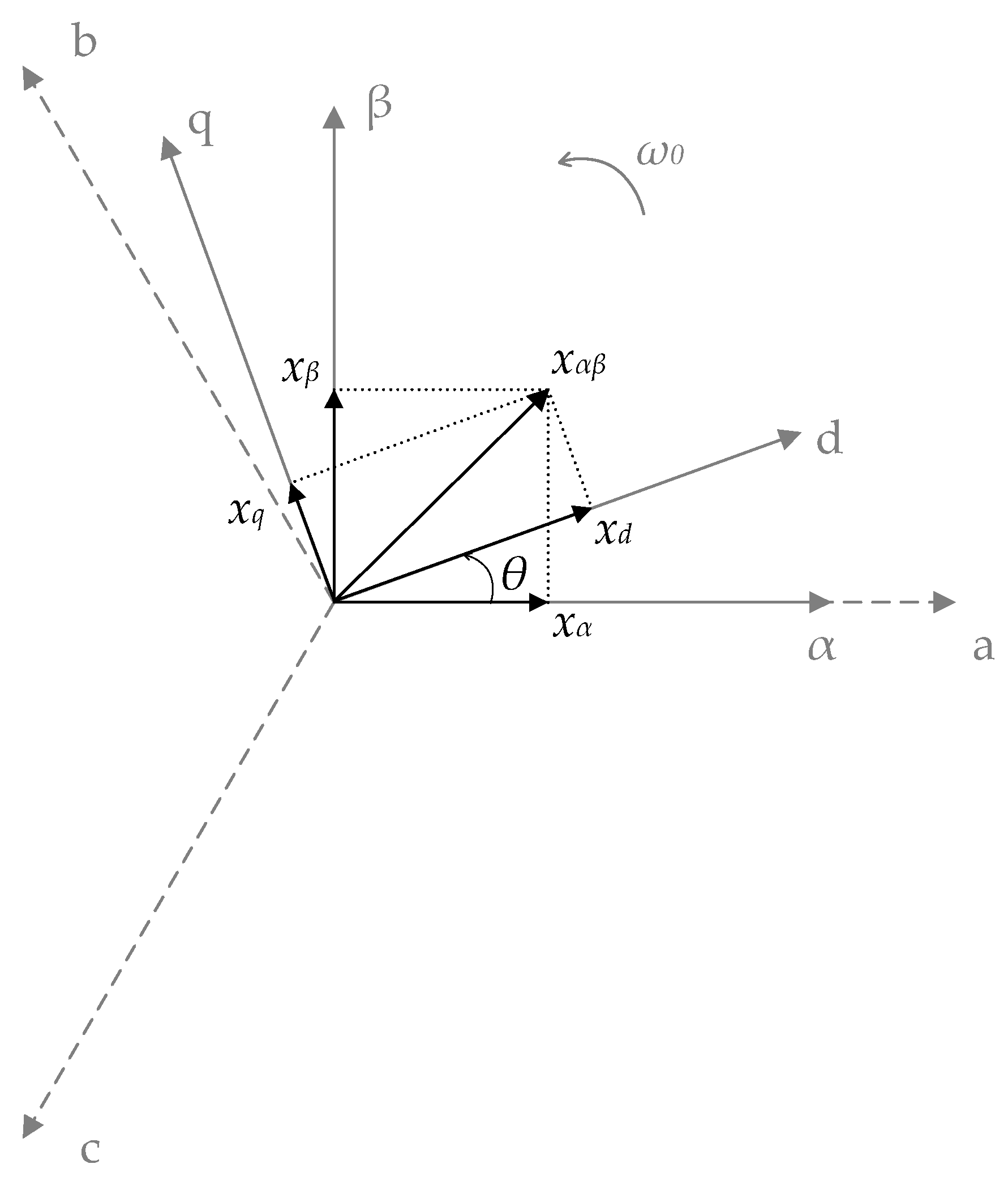
Three-phase quantities, whose sum equals zero, can be represented by a single vector in the complex plane. Figure 4 illustrates the relationships between the stationary (αβ) coordinate system and the rotating (dq) coordinate system, which rotates at synchronous speed θ = ω1t. The orthogonal projections of the vector xαβ onto the axes of the three-phase system provide the instantaneous values of the three-phase quantities. If the projection is performed onto the stationary orthogonal axes αβ instead of the phase axes, we obtain the Clarke or diagonal components.
To write the equations in the state space, we first define the state variables xi, which form the state vector x. For the given topology shown in Figure 1, with the equivalent circuit shown in Figure 2, the voltage on the capacitor uc and the current of the system inductance is are chosen as the state variables. The coupling impedance of the active part of the filter is omitted, and the load impedance is considered as an infinite value, which represents the worst case (ideal harmonic current source). Other assumptions are that the converter voltage uaf influences the dynamics of the system inductance current is but does not directly control the capacitor voltages uc, and that disturbances from the source voltage and the load current impact the dynamics of the inductor current and the capacitor Cpf voltage.
The state-space mathematical model describes a linear system with n first-order differential equations, where n indicates the order of the system. The equations are written in a three-phase system, for one phase. The variables are given in vectors, and the algebraic and differential equations are in matrix form.
According to Kirchhoff’s laws for the given topology (Figure 2) and after a transformation to the dq-coordinate system, we obtain the following:
d d t i s d i s q u c d u c q = R s L s ω 1 L s 0 ω R s L s 0 1 L s 1 C p f 0 0 ω 0 1 C p f ω 0 i s d i s q u c d u c q + 1 L s 0 0 1 L s 0 0 0 0 u a f d u a f q + 1 L s 0 0 0 0 1 L s 0 0 0 0 1 C p f 0 0 0 0 1 C p f u s d u s q i l d i l q .
Next, the state vector, the input vector, and the vector of external variables for the system shown in Figure 1 are defined:
x T = i s d i s q u c d u c q ,
u T = u a f d u a f q ,
d T = u s d u s q i l d i l q ,
where
T is the operator for matrix transposition,
isd,q are the d- and q-components of the system current,
ucd,q are the d- and q-components of the capacitor voltage,
uafd,q are the d- and q-components of the voltage of the active filter (reference value),
usd,q are the d- and q-components of the supply voltage,
ild,q are the d- and q-components of the load current.
A linear system of n first-order differential equations is written as
x ˙ = A x + B u + E d ,
and
y = C x .
The matrices in (9) and (10) are given as follows:
A = R s L s ω 1 L s 0 ω R s L s 0 1 L s 1 C p f 0 0 ω 0 1 C p f ω 0 , B = 1 L s 0 0 1 L s 0 0 0 0 ,
E = 1 L s 0 0 0 0 1 L s 0 0 0 0 1 C p f 0 0 0 0 1 C p f , C = 1 0 0 0 0 1 0 0 0 0 0 0 0 0 0 0 .
We assume that the parameters Rs, Ls, and Cpf in (11) and (12) are constant. The mathematical model provides the state of the network shown in Figure 1 at any time. The system is linear and time-invariant in the dq-coordinate system. Due to Park’s transformation, the equations are coupled via the coupling term related to the fundamental frequency of the system or the angular velocity of the rotating coordinate system. By adjusting the angular velocity ω, System (9) can be used for different harmonic frequencies. In the next subsection, the mathematical model will be used to derive the state-space controller.
In Figure 5, the mathematical model is represented graphically.

3.2. Design of the Control Algorithm in State Space

If the measurements of all the state variables are available, the control law can be expressed as follows:
u = K x
where K is the control matrix.
The purpose of the control is to keep the difference rx as close to 0 as possible, where r is the vector of the reference values. The above control law does not allow this because there are external variables d (“disturbances”) present that cannot be influenced (e.g., harmonically distorted supply voltage and distorted load current).
This problem is addressed by adding an integral term. The system of equations in the state space is upgraded with a new state variable:
x I = 0 t ( y ( τ ) r ( τ ) ) d τ ,   o r
x ˙ I = r y .
We obtain the following control equation (without feedback):
x ˙ x ˙ I = A 0 C 0 x x I + 0 1 r + B 0 u + E 0 d y = C 0 x x I
Given that System (9) is controllable, the linear–quadratic regulator (LQR) can be written as follows:
u = K x x I .
xI is the output from the integrator, defined as follows:
x I = 0 i s d , q * τ y τ d τ , o r
x ˙ I = i s d , q * y .
Inserting (18) into (9) results in the matrix equation of the regulator in dq-coordinates without a feedback loop:
d d t i s d i s q u c d u c q i s d i s q = R s L s ω 1 L s 0 0 0 ω R s L s 0 1 L s 0 0 1 C 0 0 ω 0 0 0 1 C ω 0 0 0 1 0 0 0 0 0 0 1 0 0 0 0 i s d i s q u c d u c q i s d i s q + 0 0 0 0 0 0 0 0 1 0 0 1 i s d , r e f i s q , r e f + 1 L s 0 0 0 0 1 L s 0 0 0 0 1 C 0 0 0 0 1 C 0 0 0 0 0 0 0 0 u s d u s q i b d i b q .
The matrix equation of the regulator in dq-coordinates with a feedback loop is, thus, the following:
x ˙ x ˙ I = A B K B K I C 0 x x I + 0 1 i s d , q * + E 0 d ,
y = C 0 x x I .
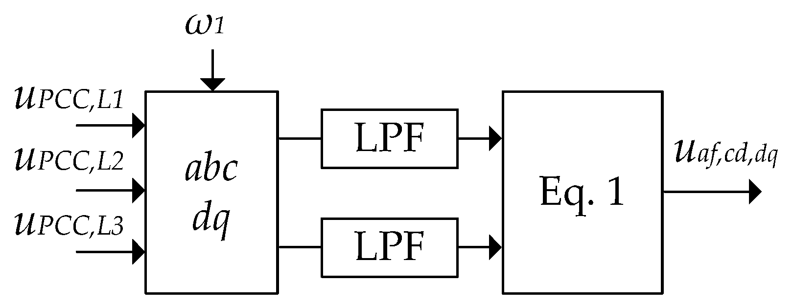
The diagram of the main current loop of the regulator in state space is shown in Figure 6. The DC voltage controller and the control branch for current redirection are shown in Figure 7 and Figure 8. The outputs of all the control branches of the controller are ultimately summed into a combined output variable, uaf, which represents the input to the modulator.
The next important step in designing the state-space regulator is determining the constants K and KI. To determine the constants, we need the values of the network elements, which will be presented in the next section.

3.3. DC Voltage Regulation

The proper regulation of the voltage on the DC side of the converter is essential for the efficient operation of the device. The principle of DC voltage regulation is based on active power, where charging the capacitor with active power raises the DC-side voltage, and discharging the capacitor lowers it. According to pq-theory, the DC component in the dq-coordinate system represents the active power component; hence, regulation is performed in the synchronous-rotating coordinate system.
As shown in Figure 7, the difference between the measured and filtered actual DC voltage and the reference voltage value serves as the input for the PI component, whose output corresponds to the d-component (the reference value of the q-component is zero). Using a low-pass filter with a tuning frequency of 20 Hz, we remove harmonic currents and other distortions from the measured voltage. The output of the regulator is added to the reference voltage value.

3.4. Redirection of the Fundamental Current Component

To achieve the lowest current ratings in the active part of the filter, the fundamental frequency filter current must be redirected to the parallel circuit of the double-tuned filter. For this purpose, a control branch is added to the main current loop of the regulator, which is shown in Figure 8. In the control branch, the voltage drop across the parallel circuit is calculated as it would be without the influence of the active part of the filter, according to Equation (1). Consequently, a very small component of the fundamental frequency current flows through the active part of the filter, which is necessary for charging the DC capacitor.

3.5. General Guidelines for Designing Hybrid Filters

In this section, a concise presentation of the general design guidelines for the hybrid filter described in this paper is provided. These guidelines are intended to assist engineers and researchers in effectively designing, implementing, and optimizing hybrid filters for improved harmonic filtering and resonance damping in electrical power systems.
  • Topology and Component Design
Presented parallel topology: Utilize a parallel connection of a three-phase two-level voltage-source converter with a double-tuned passive filter. This configuration reduces the power ratings and costs.
Component selection: Select and parameterize double-tuned passive filters based on the dominant harmonic frequencies in the network. Ensure that the passive components (capacitors and inductors) are tuned close to the present harmonics to improve harmonic attenuation and minimize the physical size of the active components.
Calculate necessary ratings: Use detailed equations from this paper to determine the minimal active-part ratings required for effective performance, considering the tuning frequencies and expected harmonic levels.
2.
Control Algorithm Design
Develop a state-space control strategy: Design a state-feedback controller tailored to each harmonic frequency. This controller should be based on a state-space mathematical model of the hybrid filter system.
Implement LQ regulator: Utilize a linear–quadratic regulator derived in the dq0-coordinate system.
Parameter optimization: Use mathematical modeling to derive the necessary control parameters. Ensure that the regulator can track reference values effectively while managing the dynamic behavior of the hybrid filter under varying load conditions.
3.
Simulation and Validation:
Modeling and simulation: Simulate the hybrid filter using EMT software like PSCAD to evaluate performance under different scenarios, such as steady-state and transient conditions.
Performance assessment: Analyze the filter’s effectiveness in real-time simulations to ensure that it meets the desired filtering characteristics, focusing on the reduction inharmonic distortions and maintaining system stability.
4.
Measurement Methods for Passive Components
For designing a reliable hybrid filter, accurately characterizing the passive components, such as capacitors and inductors, is crucial. State-of-the-art measurement methods are essential to ensure proper characterization, directly impacting the filter’s performance:
Impedance analyzers: Advanced impedance analyzers offer comprehensive impedance measurements across various frequencies. These devices help in understanding the frequency-dependent behavior of inductors and capacitors, which is vital to designing filters which operate effectively across a range of harmonic frequencies.
Network analyzers: Vector network analyzers (VNAs) can measure the complex impedance of passive components with high precision. VNAs are particularly useful for characterizing the parasitic elements of inductors and capacitors, which can significantly impact the performance of hybrid filters. For example, the authors in [26] discuss using VNAs to overcome the effect of test fixtures on the measurement of parasitic in capacitors and inductors. They highlight the importance of compensating for parasitic effects to ensure accurate impedance measurements.
Quality factor (Q) measurement: The quality factor, or Q, of inductors and capacitors is a critical parameter that affects filter performance. High-Q components result in lower energy losses and better filtering characteristics. Instruments like Q meters or impedance analyzers can accurately measure the Q factor. The authors in [27] describe using VNA-based fixture adapters for wideband accurate impedance extraction of single-phase EMI-filtering chokes, emphasizing the need for systematic parasitic de-embedding to achieve precise measurements up to 120 MHz.

4. Filtering Characteristics’ Analysis

For the analysis of the filtering characteristics and the mathematical analysis of the presented hybrid filter along with its controller, a concrete example of a network and device is needed. In this section, a general description of the modeled network will be provided first, where the values of circuit elements, filters, and some calculations will be presented. Next, the method for setting the parameters of the main current loop of the controller in state space will be demonstrated. At the end of this section, the filtering characteristics will be displayed. The simulation results will be presented in the following section.

4.1. Studied Network Description

The network used to illustrate the operation of the hybrid filter and study the effectiveness of the presented control algorithm has been modeled in the digital simulation software package PSCAD, version 4.6.3. For the test network, a real industrial network that represents an example of an industrial network with a poorly designed passive compensator has been chosen, which causes significant resonant amplifications of current harmonics in the network. The simplified diagram of the simulated system is shown in Figure 1, while a more detailed diagram of the load model provided in Figure 9.
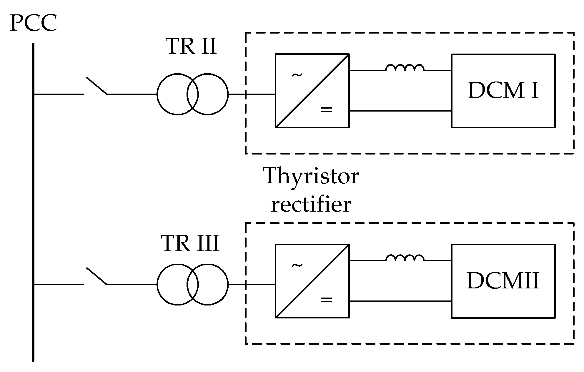
The industrial 35 kV network is powered through a 110 kV transmission network, which is depicted in Figure 1 as a stiff grid with a short-circuit power of Ssc. A stiff voltage source, which generates a constant voltage us at the terminals, is connected in series to a short-circuit impedance Zs = Rs + jωL. This has been determined based on the 110 kV voltage level and the system’s short-circuit capacity of 3750 MVA. A transformer TRI, 110/35 kV, with a rated power of 20 MVA and a short-circuit voltage of 10.82%, is used to power the 35 kV network. The resistive losses in the copper of the transformer represent approximately 0.005 p.u. On the secondary side of transformer TRI, a passive compensator, rated at 5.4 MVAr and tuned to 395 Hz, is connected. Also connected to the network are two thyristor-powered DC motors, DCM I and DCM II (see Figure 9), with powers of 2.5 MVA and 2.15 MVA, respectively, which are the main sources of harmonic distortions in the network. The harmonic components of the nonlinear load are given by h = 6k ± 1, where k = 1, 2, 3… Other consumption in the network is modeled with a resistive load Zl, representing 5.2 MW and 2.7 MVAr of power. The network parameters are given in Table 1.

4.1.1. Parameters of the Active Filter

The existing passive compensator has been upgraded to a hybrid filter, as shown in Figure 1, with the tuning frequencies of the passive part equal to ft1 = 245 Hz and ft2 = 395 Hz. To the parallel circuit of the passive part, a voltage converter has been connected. A three-phase two-level topology has been selected for the voltage converter, which is modeled with IGBT switch models and anti-parallel connected diodes, as shown in Figure 1. The LCL output filter significantly reduces the distortion caused by the switching actions of the voltage converter. The tuning frequency of the output filter is approximately 3700 Hz.
As shown in Table 2, which provides basic data on the active part of the filter, the rated power is only 135 kVA, which is approximately 2.5% of the power of the passive part and 2.9% of the power of the nonlinear load.

Determining the DC Voltage Level

The DC side of the converter is modeled with a capacitor with a capacitance of CDC and a resistance of RDC. To minimize the fluctuation in the DC voltage, a capacitor with a capacitance of 1850 µF has been chosen. The DC voltage is regulated to a value of 4 kV. Using sinusoidal pulse-width modulation modeled with a maximum modulation factor of 0.5 under static conditions, this means that the maximum peak voltage on the AC side is 2 kV.
From Equation (1) follows Equation (23), which determines the peak value of the fundamental component of the voltage on the AC side of the converter:
U a f , 1 = a b s 35 3 2 1 1 245 50 2 + 1 1 395 50 2 k V = 0.55   k V
From Equation (2) follows the expression below, which determines the peak value of the harmonic voltage.
U a f , h = a b s U s , h + j X C , h I b , h
If we assume that the voltage distortion at the connection point of the hybrid filter, i.e., at the 35 kV busbars, is negligible (typically around 2%) and that the load current contains only the seventh harmonic with an amplitude of 15% of the fundamental component, then the following applies:
U a f , 7 = a b s 0 + j 1 2 π 350   H z 13.81   μ F 9.8 5 2 + 6.2 2 3 35   k V 1.61   k V
In the worst-case scenario (if the amplitudes are added), the voltage on the AC side of the converter will therefore reach an amplitude of about 2.15 kV. Hence, a voltage of 4 kV on the DC side of the converter is the minimum necessary voltage for effective harmonic filtering.

4.2. Setting Parameters of the Main Current Loop

In this subsection, the parameters of the LQ regulator will be set for the specific case of the network shown in Figure 1 and Figure 9. The parameters of the regulator in state space (the regulation matrices K and KI) are often tuned using an estimator, as provided by Equation (26).
J = 0 y ( t ) Q y ( t ) + u ( t ) R u ( t ) d t
In this process, the following weighting factors are used:
Q = d i a g 0 0 0 0 2.8 2.8
and
R = d i a g 2 1 0 5 2 1 0 5 .
The term “diag” indicates that these are diagonal matrices. The matrix Q specifies the weight of individual state variables. Since only the state variables xId and xIq are important for the proper operation of the regulator, their values are set to 2.8, while other variables have weights of 0. The matrix R allows for the determining of the weight of individual control variables. For linear systems, the matrix K is given by
K = R 1 B T P ,  
where matrix P is obtained by solving the following algebraic Riccati equation:
A T P + P A + C T Q C P B R 1 B T P = 0 .
Finally, the matrix [K KI] equals
K K I = 1.23 0.00 0.01 0.036 104.10 354.20 0.00 1.23 0.036 0.01 354.20 104.10 .
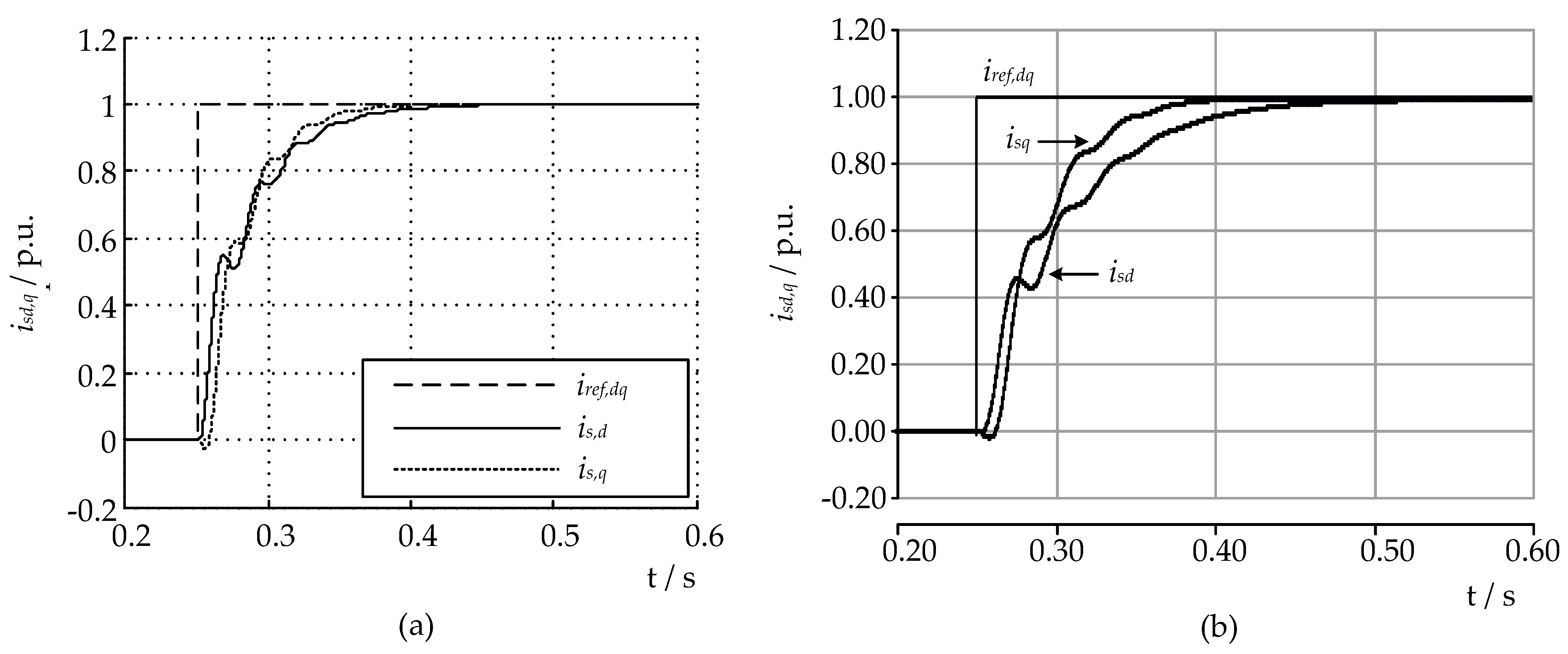
The results in Figure 10a,b show the fifth harmonic d- and q-components of the network current for the calculated and simulated cases. The reference current values are initially 0 p.u., and then, at 250 ms, they step-change to 1 p.u., where 1 p.u. corresponds to the value of the fifth harmonic component in the load current. As evident from the figure, the actual current values asymptotically follow the reference values, without significant oscillations or transients. Furthermore, by comparing the calculated and simulated quantities, we can see that the waveforms of the same quantities in (a) and (b) are very similar. From this, it can be concluded that Mathematical Model (9) accurately describes the actual network shown in Figure 1 and Figure 9.

4.3. Filtering Characteristics

The filter characteristics are obtained by calculating the mathematical model of the network with the connected device. When the model is difficult to derive or the mathematical analysis is highly complicated, the impedance characteristics can also be determined through special simulation procedures, which will be demonstrated for the case of a hybrid filter controlled by a state-space regulator in the following section.

4.3.1. Standalone Passive Filter

The existing passive filter in the industrial network is tuned to 395 Hz and is used for reactive power compensation. Figure 11 shows the frequency response of the network, obtained by calculating the model of the network in Figure 1. The characteristics are displayed as the ratio of equivalent impedances, normalized to the impedance at the fundamental frequency. The graph shows parallel impedance. As evident from the figure, the parallel resonance point is very close to the fifth harmonic component, where the impedance reaches a very high value (69 dB) of gain. The compensator is in resonance at the fifth harmonic.

4.3.2. State-Space Control Algorithm’s Filtering Characteristics

When it is difficult to precisely determine the transfer function of the device and the control algorithm or when the mathematical analysis of the frequency characteristics of the transfer function is complex, frequency-scanning methods in simulation programs can be used. For the frequency analysis of the hybrid filter controlled by a state-space regulator, we utilized a scanning method that had been presented in [33], where the authors studied the frequency characteristics of the UPFC system. Since the hybrid filter is intended for filtering current harmonics caused by a nonlinear load, it is sufficient to perform the scanning only from the load side.
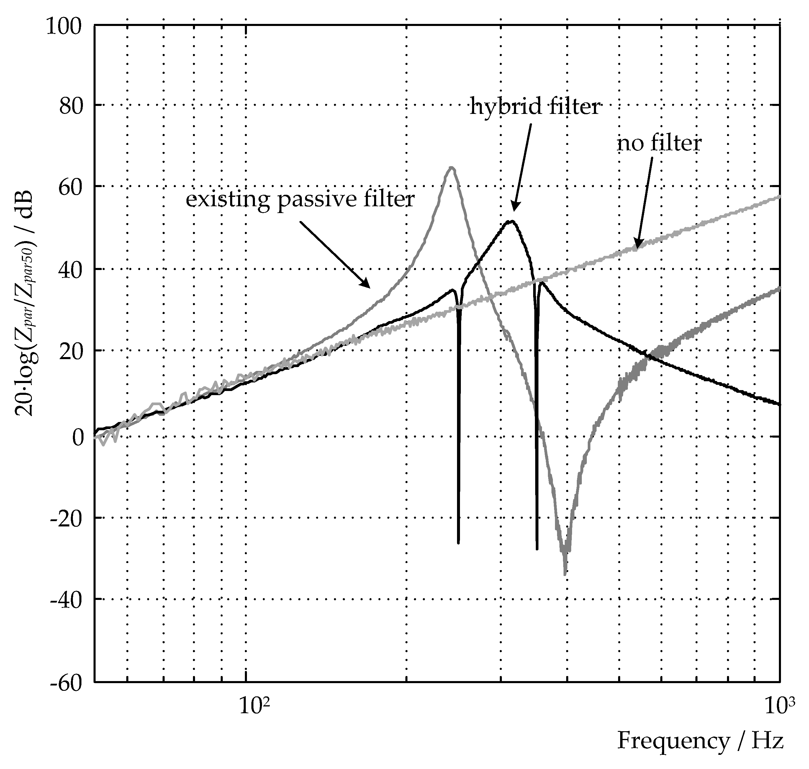
The results of the frequency scanning of the hybrid filter with a state-space regulator are shown in Figure 12, where three characteristics are displayed: without filter, passive filter only, and hybrid filter. Since the main sources of harmonic distortions in the network are two thyristor-driven DC motors (DCM I and DCM II in Figure 9), only the parallel impedance characteristics are shown. As it can be seen from the figure, the scanning was performed in the frequency range from 0 to 1000 Hz, and the controller, for simplification, filtered only the fifth and seventh harmonic components. By comparing the form in Figure 12, which shows the frequency characteristics of the passive compensator, and the characteristics for the passive compensator from Figure 11, we can see that the characteristics match very well.
Based on the frequency characteristics, it can be concluded that the device will selectively filter the fifth and seventh harmonic components. Given the very low impedance values at these frequencies, effective filtering is expected. Additionally, the parallel resonance of the passive part is damped and shifted to a less problematic frequency range.
The filtering characteristics will be studied in more details in Section 5 using simulations.

5. Hybrid Filter Performance Assessment

5.1. Modeling of Electrical Networks and Devices

The foundation of any program for digital simulation consists of representing an electrical circuit in the form of a system of differential equations, which the program numerically solves. In PSCAD, all capacitances and inductances in the circuit are replaced with a parallel connection of a resistor and a current source. Numerical accuracy is especially important for semiconductor switches, which typically change states very rapidly, even at frequencies up to 10 kHz. In programs which use a fixed time interval, switches can only toggle at times that are multiples of the time step. This limitation can lead to the generation of non-characteristic harmonics and voltage spikes in the numerical result. The problem of accuracy can be addressed by shortening the time interval, which significantly prolongs the simulation time. Another solution involves introducing a variable time interval, where interpolation is used to determine the exact timing of the semiconductor switch toggling between two time steps. This solution has proven to be more accurate and much faster than reducing the time step [34].

5.1.1. Modeling of the Control Algorithm

The regulator is one of the most important components of power electronics devices. It can be divided into three fundamental parts:
capturing and sampling system quantities;
processing signals and calculating reference values;
generating pulses for triggering switches.
The mathematical model of the hybrid filter has been derived under the assumption that the voltage converter (active filter) generates an ideal voltage uaf at the output terminals—the converter is considered an ideal voltage source. The output voltage of the voltage converter cannot be represented with three ideal voltage sources, but through a switching function which determines the sequence of voltage pulses with an amplitude equal to the current value of the DC voltage amplitude. These pulses are usually generated based on pulse-width modulation; hence, the output voltage is not of an ideal form but contains various harmonic components, including those with frequencies around the selected switching frequency of the modulator. Consequently, not only the desired harmonic components appear in the converter’s output current, but also unwanted components which result from the triggering of semiconductor switches.

5.1.2. Measurements and Synchronization

The performance and speed of the control algorithm are largely dependent on the sampling of measured quantities. In simulations, we will sample measurements at a frequency of 10 kHz. This frequency also determines the switching frequency of the semiconductor switches of the voltage converter, which is often the same. Due to the limitation of the switching frequency of semiconductor switches and, thus, higher switching losses, a switching frequency that is half the sampling frequency is also often used, but this does not achieve significant savings with lower-power converters [34].
The time delay of the regulator, resulting from measuring, is fixed in the simulations and equal to one sampling period, or 0.1 ms at a 10 kHz sampling rate. Thus, with a delay of one sampling period, the output regulation voltage of the converter appears at the output of the regulator, which is used on the modulator which translates the input voltage signal into the output switching function, determined for each semiconductor switch. Pulse-width modulation (PWM) with a carrier signal frequency of 10 kHz is used.
For the needs of transformations of quantities into or from d-q components, the simulated model needs to be synchronized to the frequency of the network voltage. In the simulated case, synchronization is performed using a PLL (phase-locked loop) module from the PSCAD library.

5.1.3. Modeling of the Coupling Impedance

Active filters are connected to the network through a coupling impedance, commonly referred to as an output filter. This has the function of filtering high harmonic components that result from the switching actions. The implementations of coupling impedance can broadly be divided into first-order inductive filters (L), second-order filters (LC), and third-order filters (LCL). Since the LC filter is just a special case of the LCL filter, where the influence of the second inductance is assumed to be negligible, we will only shortly discuss the design of LCL filters.
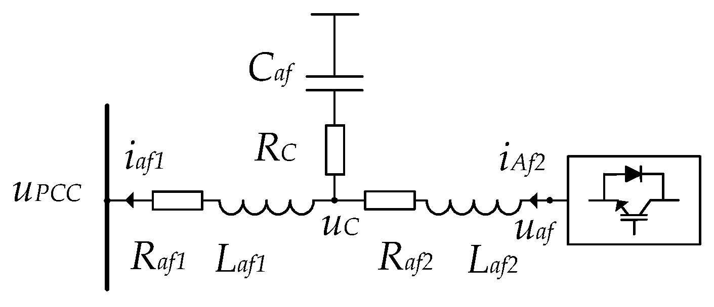
Recently, due to the better filtering characteristics for filtering harmonics resulting from switching actions, LCL filters are increasingly being used. Such a filter is shown in Figure 13. Laf1 and Raf1 are the inductance and equivalent series resistance on the network side of the filter; Laf2 and Raf2 are the inductance and equivalent series resistance on the converter side; Caf and Rc are the capacitance of the filter and series resistance, which also serves as a damping resistor, sometimes added to dampen resonant amplifications; and iaf1 and iaf2 are the currents on the network and converter sides, respectively [35].
The relationships between the voltages and currents in Figure 13 can be described with transfer functions:
Y a f 1 s = I a f 1 s U C s U P C C s = 1 s L a f 1 + R a f 1 ,
Y a f 2 s = I a f 2 s U a f s U C s = 1 s L a f 2 + R a f 2 ,
Z C s = U C s i a f 2 s i a f 1 s = 1 s C a f + R C ,
Using the above expressions, we can determine the transfer function of the output LCL filter, which is shown in block diagram form in Figure 14. Depending on the current used in the control algorithm of the device, the transfer functions of the LCL filter are given as follows:
H L C L a f 2 s = I a f 2 s U a f s = Y a f 2 s 1 + Y a f 1 s Z C s 1 + Y a f 2 s Z C s + Y a f 1 s Z C s ,
H L C L a f 1 s = I a f 1 s U a f s = Y a f 1 s Y a f 2 s Z C s 1 + Y a f 2 s Z C s + Y a f 1 s Z C s .
The advantages of the LCL filter compared to a simple L filter can be summarized as follows [35]:
Faster attenuation of gain at frequencies above the tuning frequency fres, which is a consequence of the higher-order (third-order) transfer function. Consequently, the LCL filter better filters harmonics that result from the switching of semiconductor switches. This is evident from Figure 15, which shows the Bode plots of both filters.
Smaller dimensions of components to achieve the same filtering characteristics, which directly follows from the previous point.
Disadvantages of the LCL filter compared to the L filter:
More complex structure. There have been many publications in the literature on the various design issues of output LCL filters.
Resonance occurs at fres, which can lead to the unstable operation of the device or significant harmonic distortions of the output quantities. Resonance can be dampened with a properly sized resistor, but this causes additional energy losses.
Due to variations in the parameters of the filter elements and the network, the tuning frequency of the filter can change significantly. Likewise, the resonance frequency also changes, which can lead to unwanted resonant amplifications of harmonics.
The resonant frequency is determined by the following expression:
f r e s = 1 2 π L a f 1 + L a f 2 C a f L a f 1 L a f 2 .

5.1.4. Implementation Aspects

To implement the proposed hybrid filter topology, the following existing power electronics devices can be utilized:
Voltage-Source Converter: A three-phase, two-level VSC is recommended for its simplicity, cost-effectiveness, and ease of control. Existing devices such as IGBT (Insulated Gate Bipolar Transistor) modules from different manufacturers can be used.
DC-Link Capacitor: High-voltage capacitors are essential for stabilizing the DC side of the converter. Suitable capacitors include those with a capacitance of around 1850 µF and a voltage rating of 4 kV.
LCL Filter Components: Inductors (Laf1, Laf2): Coupling inductors with inductance values of 1 mH and 4 mH.
Capacitors (Caf): Filtering capacitors can be selected from different manufacturers, with capacitance values of 7 µF.
Resistors: Damping resistors for the LCL filter, with a resistance value of 150 mΩ, are recommended to limit inrush currents.
Control System: A digital signal processor or field-programmable gate array from manufacturers like Texas Instruments or Xilinx can be used to implement the state-feedback controller.

5.2. Simulation Results

The subsequent sections will present the results of simulations of the detailed model of the proposed hybrid filter. Voltages and current waveforms in a steady state and during various transient conditions will be shown. For clarity and due to the symmetric conditions, only one phase (phase L1) will be shown for all quantities. The goal of the simulation is to analyze and evaluate the static and dynamic behavior of the hybrid filter, i.e., to verify the characteristics of harmonic filtering in steady conditions and the durations of individual transient phenomena and their impact on other quantities.
In the simulations, the network described in Section 2 has been used. The hybrid filter functions as a filter for current harmonics, specifically filtering the 5th, 7th, 11th, 13th, 17th, and 19th harmonic components of the system current is. As a result, the filtered harmonic components do not continue to flow from the load side into the network but are instead diverted via the hybrid filter. This significantly reduces the remaining total harmonic distortion of the network current.

5.2.1. Steady-State Conditions

The values of individual harmonics in the voltage at the filter PCC (uPCCL1) and in the system current (isL1) and their THD values (considering harmonic components up to the 40th harmonic order) are presented in Table 3 (as percentages relative to the fundamental component). The values are given for two simulated scenarios: one with only the passive filter in operation and the other with the proposed hybrid filter in operation. The network and load model are identical in both cases (see Figure 1 and Figure 9). As it can be seen from the results, the total harmonic distortion in the first scenario, with only the passive filter, is quite high, reaching nearly 5% in voltage and over 15% in current. The fifth harmonic component contributes most to the total distortion, which is expected based on Section 4.3.1, where it has been shown that the passive filter is in resonance with the network at this harmonic component. The simulation results on the right side of Table 3 show that using the proposed hybrid filter (or upgrading the passive part with an active filter) improves the total harmonic distortion by approximately tenfold. The value of the fifth harmonic in the current is, thus, below 1%, and, therefore, the values of the total harmonic distortion of voltage and current are around 1% and 1.2%, respectively.
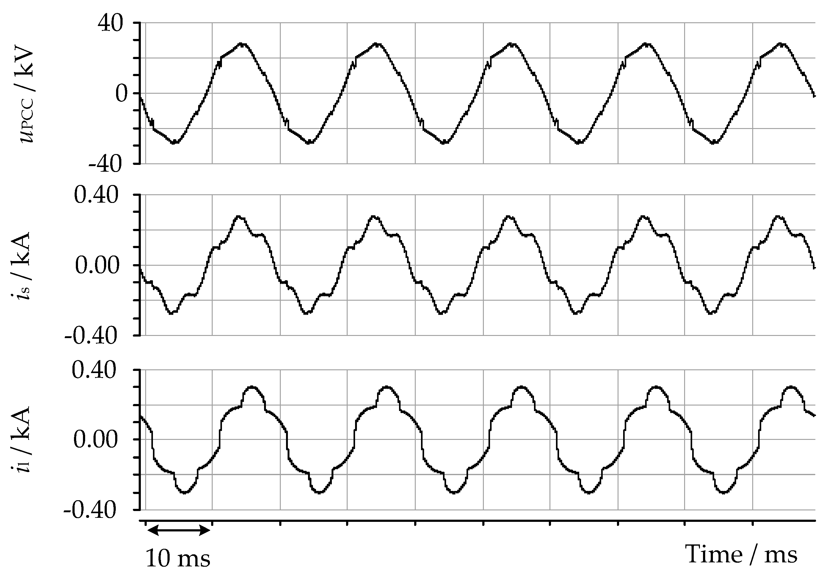
Figure 16, where waveforms of the voltages and currents for a standalone operation of the passive filter are shown, reveals that, consistent with Table 3, both voltage uPCCL1 and system current isL1 are significantly distorted. In the voltage, characteristic notches can be observed, which is a consequence of the steep changes in currents of thyristor-powered loads. The load current has a typical form for this type of electrical load, with characteristic harmonics of 6·n ± 1, and an inductive character. The system current is in phase with the voltage, indicating proper reactive power compensation of the load.
In addition to the quantities shown in Figure 16, Figure 17 also shows the active part current (output current of the LCL filter) and the voltage on the DC side of the converter. The figure shows the simulation results of the hybrid filter under steady-state conditions. As it is evident from the figure, with the same load current as in the previous figure, the system current is now nearly a perfect sinusoidal shape. Consequently, the harmonic distortion of the voltage is also very small. No higher-frequency harmonics are noticeable in the current, indicating that filtering with the LCL filter is effectively implemented. Based on this figure, we can conclude that the filter’s operation in the described scenario is effective and stable.

5.2.2. Transient-State Conditions

In the simulations below, the LQ regulator has been tested using an accurate model of the hybrid filter, observing its operation during startup and its response to changes in the load current. Note that the simulations utilize a simplified startup procedure of the active filter, involving direct connection to the operation. Namely, as it is well known, before starting active filters or static compensators (switching on the main circuit breaker), it is necessary to ensure a sufficiently high voltage on the DC side of the converter to prevent excessively high startup (charging) currents. In practice, precharging the capacitors is most often achieved through charging resistors with diode rectifiers.

Startup Behavior

As it can be observed in Figure 18, the startup of the active part of the hybrid filter in the proposed topology does not reach high values, despite the capacitor on the DC side not being precharged. The peak inrush current observed is approximately 85 A, and the voltage at the PCC stabilizes itself at 29.2 kV peak within 180 ms. This is largely due to the low voltage at the PCC of the active part of the filter, which is equal to the voltage drop across the parallel circuit of the double-tuned passive part, given by Equation (1), and the active redirection of the fundamental current component from the active part to a parallel circuit—Section 3.4. High inrush currents can also be caused by charging the capacitor of the output LCL filter, which is resolved either by using damping resistors (a passive method) or active damping techniques. As evident from Figure 18, the use of a resistance Raf = 150 mΩ provides good results. The results also show that the filter takes about 180 ms from startup to reach a steady state. Since the dynamics of the startup are not crucial for the operation of the device, we can conclude that the transient phenomenon of starting the active filter is appropriate.
As it can be seen from Figure 19, showing the active and reactive power components of the hybrid filter, the active filter does not significantly affect the compensation of reactive power. Initially, only the passive filter operates, and, after 50 ms, the active part is switched on. It is evident from the figure that, after the startup transient phenomenon, the reactive power output of the hybrid filter remains the same—i.e., 5.4 MVAr. The active power remains at approximately 0 MW, showing no significant fluctuations.
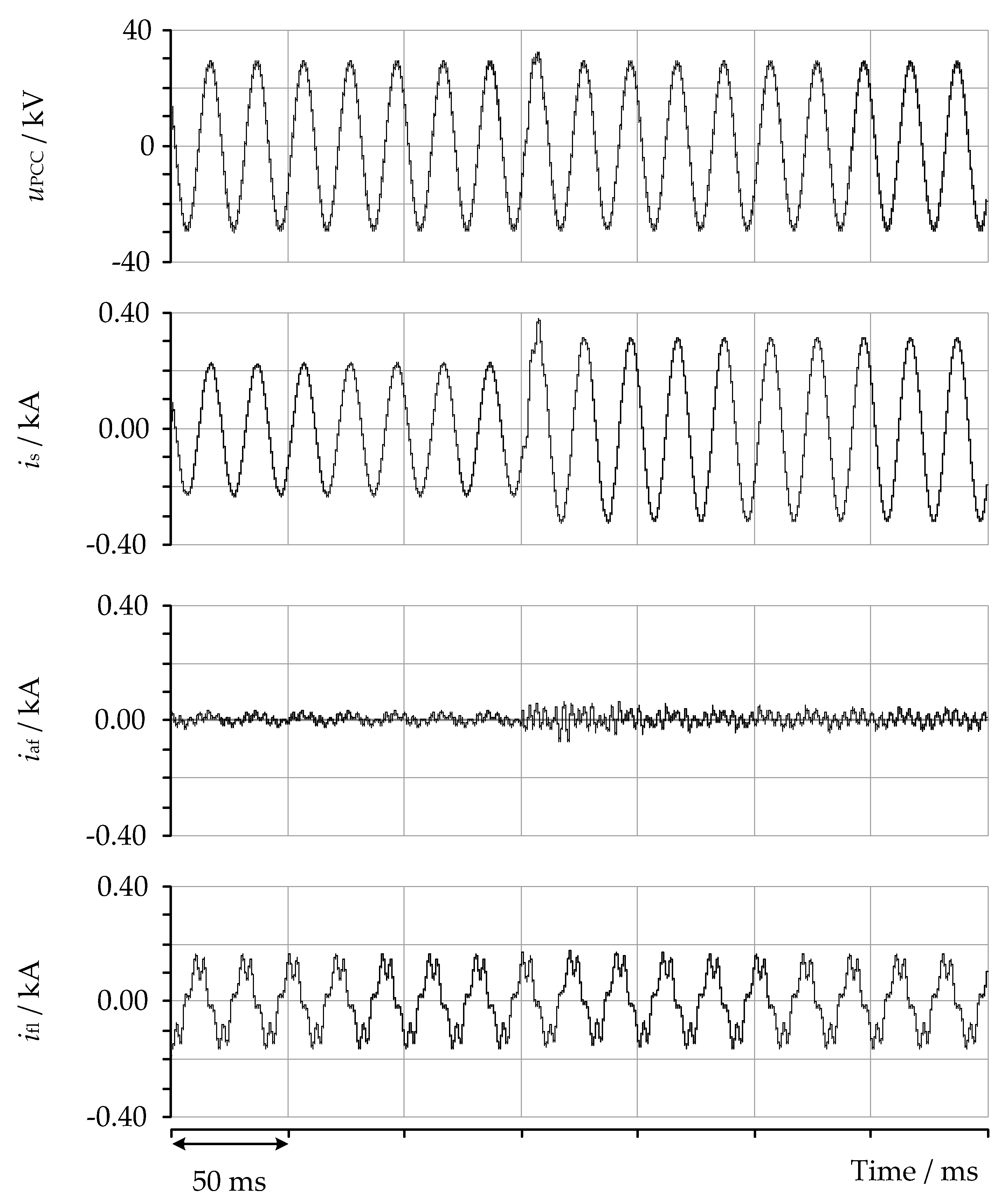
Figure 20 shows the response of the hybrid filter to a sudden change in load. Initially, the operation of the filter in a steady state is shown, and, after about 150 ms, the load is suddenly increased by 50%. The filter requires about one and a half periods of the fundamental component to reach a new steady state, with a noticeable transient phenomenon in the system current and the current of the active filter. The system current exhibit s transient spike of approximately 0.38 kA peak before stabilizing. Given the low-voltage dimensioning of the filter at the fundamental component, we can assess the transient phenomenon as appropriate. A faster response could be achieved with larger dimensions of the filter, meaning a higher voltage on the DC side of the converter and a larger coupling impedance.
Quantitative summary of the results:
Startup peak current: 85 A
Startup transient time: 180 ms
Reactive power compensation: 5.4 MVAr
Load increase response time: 30 ms
Transient current peak value: 0.38 kA

5.2.3. Analysis of Variations in Parameters of Passive Filter Elements

Despite the very precise tuning of the parameters of hybrid filter elements and the controller before installation in the network, the values of some device parameters may significantly change over time. This is particularly true for high-capacity power components such as inductors and capacitors in the passive part, where power dimensions can reach several tens of MVAr. The impact of these variations can be preliminarily analyzed by performing simulations with altered component parameters. The results of such simulations are provided below for 10% and 15% deviations from the nominal values of inductance and capacitance of the passive-part elements. Here, we have decreased the inductances and increased the capacitances, thereby shifting the resonance frequency slightly higher.

Ten and Fifteen Percent Deviations in Parameter Values

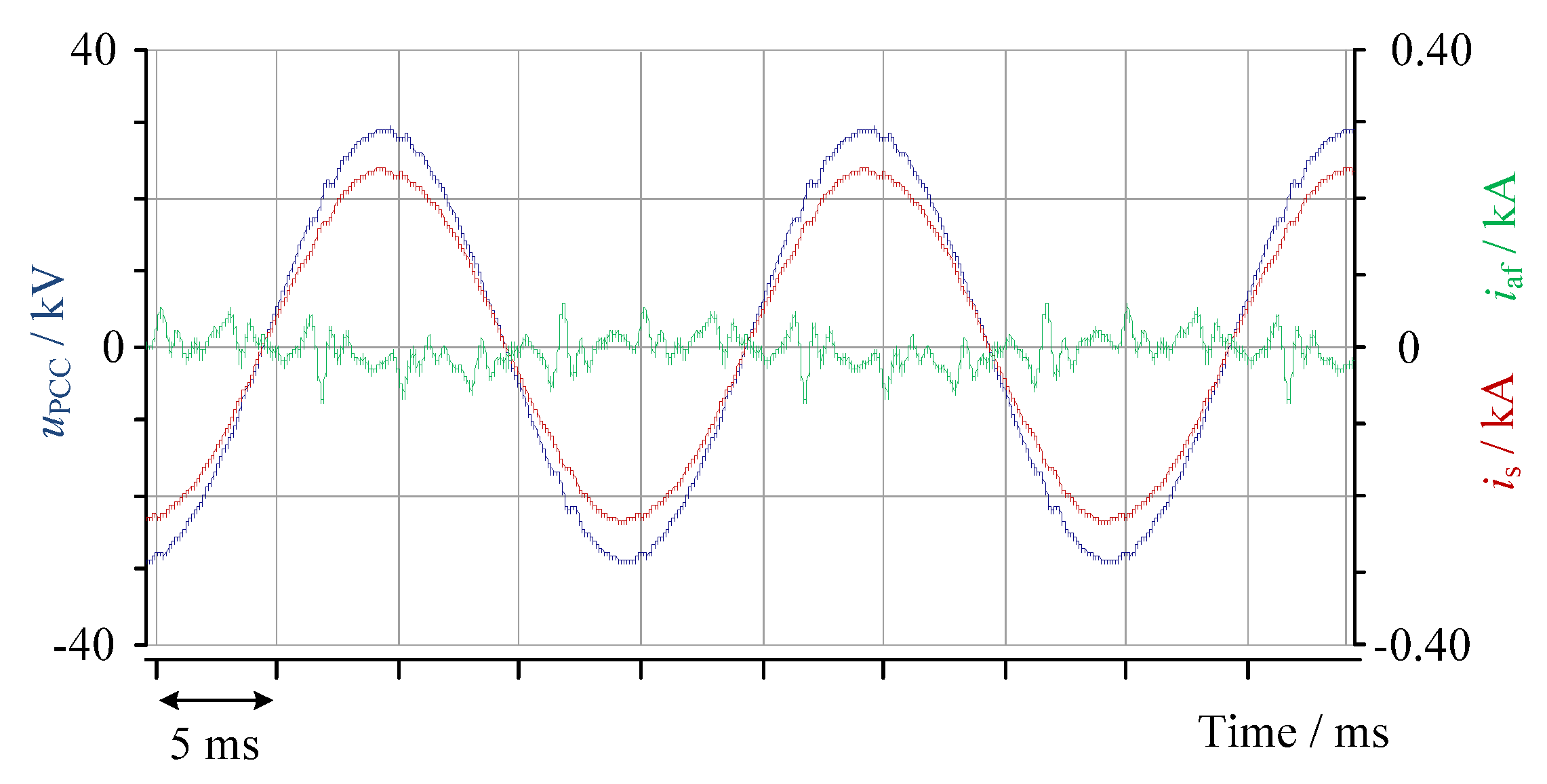
From the results in Table 4, it is evident that, with a 10% deviation from the nominal values, the hybrid filter with the proposed regulator still produces good results. It should be noted that the THD values of the current are a bit higher, having increased from 1.16% to 2.02%. However, such current distortion remains acceptable for practical applications. The same applies for the voltage, where a small increase in the THD value can also be observed, but, overall, the distortion remains well below the limits set by the standards. The simulated current and voltages waveforms with a 10% deviation are shown in Figure 21.
From the results on the right side of Table 4, it is evident that, with a 15% deviation from the nominal values, the hybrid filter still delivers good results. It can be observed that the THD value of the system (filtered) current has not significantly changed compared to the results with 10% deviations. The simulated current and voltages waveforms with a 15 % deviation are shown in Figure 22.

5.2.4. Impact on Reactive Current Compensation

Table 5 shows the impact of the hybrid filter on reactive current compensation and power quality (voltage THD) under different conditions. It demonstrates that the proposed hybrid filter significantly reduces the total harmonic distortion (THD) while maintaining stable reactive power compensation.

6. Conclusions

The main objective of this paper was to propose and validate an improved parallel hybrid filter configuration that incorporated both passive and active filter components, enhancing harmonic filtering and resonance damping in electrical power systems. The proposed topology utilized a double-tuned passive filter in parallel with a three-phase two-level voltage-source converter, which allowed for a considerable reduction in power rating and operational costs. As demonstrated, the double-tuned design of the passive filter significantly reduced the dimensions of the active part because the ratings were highly dependent on the tuning frequency of the passive components. Our findings indicated that the smallest dimensions (theoretically below 0.5%) were achieved when the passive part was tuned close to the harmonic components present in the network. Tuning the filter at 245 Hz and 395 Hz resulted in reducing the dimensions of the active part to 135 kVA, which was approximately 2.5% of the size of the passive part of the device.
In the second part of the paper, a state-feedback controller was presented, and a mathematical model was developed for designing the controller. The effectiveness of the proposed hybrid filter was demonstrated through computer simulations using a real industrial network model. The results showed that the hybrid filter offered an effective solution for reactive power compensation and harmonic filtering. The filter operated stably during changes in load current and the startup of the device, quickly reached a new steady state, and did not cause any other undesirable effects.
The proposed hybrid filter topology and control methodology provide a robust solution for enhancing power quality in industrial electrical systems. The reduction in active filter dimensions leads to lower costs and increased efficiency, making the solution feasible for widespread (industrial) application. Additionally, the approach is adaptable to other topological structures, offering flexibility in different contexts.
However, this study has some limitations. The impact of variations in the passive component parameters was analyzed, showing the design’s robustness against potential deviations expected over the operational lifespan. As it has been shown, these deviations can affect the filtering performance and, in some more extreme cases, could lead to unstable operation. This topic needs further research. Future work will also focus on a more detailed harmonic analysis, including potential supply-side distortions, and will investigate the coupling of dq-components on the stability of the control algorithms. Active damping techniques for the LCL filter and the implementation of the proposed solutions on a laboratory prototype are also planned, which will provide practical insights and validation.
Overall, this research contributes to the advancement of hybrid filtering techniques, promoting improved harmonic mitigation and power quality in industrial applications. The findings have significant implications for designing cost-effective and efficient harmonic filters.
Author Contributions

Conceptualization, L.H., K.K. and B.B.; investigation L.H.; methodology, L.H., K.K. and B.B.; project administration, L.H. and B.B.; software, L.H.; supervision, B.B.; validation, K.K. and B.B.; visualization, L.H.; writing—original draft L.H. All authors have read and agreed to the published version of the manuscript.

Funding

This research was funded by the Slovenian Research Agency (research core funding No. P2-0356).

Data Availability Statement

The original contributions presented in the study are included in the article, further inquiries can be directed to the corresponding author/s.

Acknowledgments

The authors acknowledge the financial support from the Slovenian Research Agency (research core funding No. P2-0356).

Conflicts of Interest

The authors declare no conflicts of interest.

List of Acronyms

AbbreviationDefinition
ACAlternating Current
DCDirect Current
DERDistributed Energy Resources
HPHeat Pumps
EVElectric Vehicles
EPSElectrical Power System
PQPower Quality
DTPFDouble-Tuned Passive Filter
VSCVoltage-Source Converter
HRFHarmonic Reference Frame
PIProportional–Integral
PRProportional–Resonant
PCCPoint of Common Coupling
THDTotal Harmonic Distortion
LQLinear–Quadratic
PWMPulse-Width Modulation
PLLPhase-Locked Loop

References

  1. Wang, X.; Blaabjerg, F. Harmonic Stability in Power Electronic-Based Power Systems: Concept, Modeling, and Analysis. IEEE Trans. Smart Grid 2019, 10, 2858–2870. [Google Scholar] [CrossRef]
  2. Hatziargyriou, N.; Milanovic, J.; Rahmann, C.; Ajjarapu, V.; Canizares, C.; Erlich, I.; Hill, D.; Hiskens, I.; Kamwa, I.; Pal, B.; et al. Definition and Classification of Power System Stability—Revisited & Extended. IEEE Trans. Power Syst. 2021, 36, 3271–3281. [Google Scholar]
  3. Wakileh, G.J. Power Systems Harmonics: Fundamentals, Analysis and Filter Design; Springer: Berlin/Heidelberg, Germany, 2001. [Google Scholar] [CrossRef]
  4. Srivastava, A.; Manas, M.; Dubey, R.K. Electric vehicle integration’s impacts on power quality in distribution network and associated mitigation measures: A review. J. Eng. Appl. Sci. 2023, 70, 32. [Google Scholar] [CrossRef]
  5. Sikorski, T.; Rezmer, J. Distributed Generation and Its Impact on Power Quality in Low-Voltage Distribution Networks. In Power Quality Issues in Distributed Generation; InTech: London, UK, 2015. [Google Scholar] [CrossRef]
  6. Padmanaban, S.; Sharmeela, C.; Holm-Nielsen, J.B.; Sivaraman, P. (Eds.) Power Quality in Modern Power Systems, 1st ed.; Elsevier: Amsterdam, The Netherlands, 2020. [Google Scholar]
  7. Bollen, M.H.J. Introduction to Power Quality. In Understanding Power Quality Problems: Voltage Sags and Interruptions; Wiley-IEEE Press: Hoboken, NJ, USA, 2000. [Google Scholar]
  8. Hernández-Mayoral, E.; Madrigal-Martínez, M.; Mina-Antonio, J.D.; Iracheta-Cortez, R.; Enríquez-Santiago, J.A.; Rodríguez-Rive, O.; Martínez-Reyes, G.; Mendoza-Santos, E. A Comprehensive Review on Power-Quality Issues, Optimization Techniques, and Control Strategies of Microgrid Based on Renewable Energy Sources. Sustainability 2023, 15, 9847. [Google Scholar] [CrossRef]
  9. Das, S.R.; Ray, P.K.; Sahoo, A.K.; Ramasubbareddy, S.; Babu, T.S.; Kumar, N.M.; Elavarasan, R.M.; Mihet-Popa, L. A Comprehensive Survey on Different Control Strategies and Applications of Active Power Filters for Power Quality Improvement. Energies 2021, 14, 4589. [Google Scholar] [CrossRef]
  10. Afonso, J.L.; Tanta, M.; Pinto, J.G.O.; Monteiro, L.F.C.; Machado, L.; Sousa, T.J.C.; Monteiro, V. A Review on Power Electronics Technologies for Power Quality Improvement. Energies 2021, 14, 8585. [Google Scholar] [CrossRef]
  11. Akagi, H.; Srianthumrong, S.; Tamai, Y. Comparisons in Circuit Configuration and Filtering Performance between Hybrid and Pure Shunt Active Filters. In Proceedings of the IEEE Industry Applications Conference, 38th IAS Annual Meeting, Salt Lake City, UT, USA, 12–16 October 2003; Volume 3. [Google Scholar]
  12. Bhattacharya, S.; Cheng, P.T.; Divan, D.M. Hybrid Solutions for Improving Passive Filter Performance in High Power Applications. IEEE Trans. Ind. Appl. 1997, 33, 732–747. [Google Scholar] [CrossRef]
  13. Inzunza, R.; Akagi, H. A 6.6-kV Transformerless Shunt Hybrid Active Filter for Installation on a Power Distribution System. IEEE Trans. Power Electron. 2005, 20, 893–900. [Google Scholar] [CrossRef]
  14. Corasaniti, V.F.; Barbieri, M.B.; Arnera, P.L.; Valla, M.I. Hybrid Active Filter for Reactive and Harmonics Compensation in a Distribution Network. IEEE Trans. Ind. Electron. 2009, 56, 670–677. [Google Scholar] [CrossRef]
  15. Chen, L.; Xie, Y.; Zhang, Z. Comparison of Hybrid Active Power Filter topologies and principles. In Proceedings of the International Conference on Electrical Machines and Systems, Wuhan, China, 17–20 October 2008. [Google Scholar]
  16. Shuai, Z.; Luo, A.; Zhu, W.; Fan, R.; Zhou, K. Study on a Novel Hybrid Active Power Filter Applied to a High-Voltage Grid. IEEE Trans. Power Deliv. 2009, 24, 2344–2352. [Google Scholar] [CrossRef]
  17. Luo, A.; Tang, C.; Shuai, Z.K.; Zhao, W.; Rong, F.; Zhou, K. A Novel Three-Phase Hybrid Active Power Filter With a Series Resonance Circuit Tuned at the Fundamental Frequency. IEEE Trans. Ind. Electron. 2009, 56, 2431–2440. [Google Scholar] [CrossRef]
  18. Wong, M.-C.; Pang, Y.; Xiang, Z.; Wang, L.; Lam, C.-S. Assessment of Active and Hybrid Power Filters Under Space Vector Modulation. IEEE Trans. Power Electron. 2021, 36, 2947–2963. [Google Scholar] [CrossRef]
  19. Chen, X.; Dai, K.; Xu, C.; Peng, L.; Zhang, Y. Harmonic compensation and resonance damping for SAPF with selective closed-loop regulation of terminal voltage. IET Power Electron. 2017, 10, 619–629. [Google Scholar] [CrossRef]
  20. Bhattacharya, S.; Divan, D.; Banerjee, B. Control and reduction of terminal voltage total harmonic distortion (THD) in a hybrid series active and parallel passive filter system. In Proceedings of the IEEE Power Electronics Specialist Conference—PESC ’93, Seattle, WA, USA, 20–24 June 1993; pp. 779–786. [Google Scholar]
  21. Fujita, H.; Yamasaki, T.; Akagi, H. A hybrid active filter for damping of harmonic resonance in industrial power systems. In Proceedings of the PESC 98 Record. 29th Annual IEEE Power Electronics Specialists Conference (Cat. No.98CH36196), Fukuoka, Japan, 22 May 1998; Volume 1, pp. 209–216. [Google Scholar] [CrossRef]
  22. Korhonen, J.; Silventoinen, P.; Giewont, W.; Isaksson, D. Feedforward control of isolating photovoltaic DC-DC converter to reduce grid-side DC link voltage fluctuation. In Proceedings of the IECON 2018—44th Annual Conference of the IEEE Industrial Electronics Society, Washington, DC, USA, 21–23 October 2018. [Google Scholar]
  23. Wen, J.; Zhang, M.; Lu, J.; Guan, Y.; Wu, S.; Feng, C. A Novel Control Strategy for Improving the Performance of Hybrid Active Power Filters. J. Electr. Eng. Technol. 2023, 18, 4269–4285. [Google Scholar] [CrossRef]
  24. Senini, S.; Wolfs, P.J. Analysis and Comparison of new and Existing Hybrid Filter Topologies for Current Harmonic Removal. In Proceedings of the Australasian Universities Power Engineering Conference, Ballarat, Australia, 27–30 September 1999; pp. 227–232. [Google Scholar]
  25. Herman, L.; Špelko, A. New Reference Current Calculation Method of a Hybrid Power Filter Based on Customer Harmonic Emission. Energies 2023, 16, 7876. [Google Scholar] [CrossRef]
  26. Mendez, J.B.; Freire, M.J.; Prats, M.A.M. Overcoming the Effect of Test Fixtures on the Measurement of Parasitics of Capacitors and Inductors. IEEE Trans. Power Electron. 2020, 35, 15–19. [Google Scholar] [CrossRef]
  27. Jie, H.; Gao, S.-P.; Zhao, Z.; Fan, F.; Sasongko, F.; Gupta, A.K.; See, K.Y. VNA-Based Fixture Adapters for Wideband Accurate Impedance Extraction of Single-Phase EMI Filtering Chokes. IEEE Trans. Ind. Electron. 2023, 70, 7821–7831. [Google Scholar] [CrossRef]
  28. Liu, L.; Fei, J. Extended State Observer Based Interval Type-2 Fuzzy Neural Network Sliding Mode Control With Its Application in Active Power Filter. IEEE Trans. Power Electron. 2022, 37, 5138–5154. [Google Scholar] [CrossRef]
  29. Hou, S.; Fei, J. A Self-Organizing Global Sliding Mode Control and Its Application to Active Power Filter. IEEE Trans. Power Electron. 2020, 35, 7640–7652. [Google Scholar] [CrossRef]
  30. Akagi, H. Trends in Active Power Line Conditioners. IEEE Trans. Power Electron. 1994, 9, 263–268. [Google Scholar] [CrossRef]
  31. Chen, Z.; Blaabjerg, F.; Pedersen, J.K. Hybrid Compensation Arrangement in Dispersed Generation Systems. IEEE Trans. Power Deliv. 2005, 20, 1719–1727. [Google Scholar] [CrossRef]
  32. Hafner, J.; Heumann, M.A.K. A Shunt Active Power Filter Applied to High Voltage Distribution Lines. IEEE Trans. Power Deliv. 1997, 12, 266–272. [Google Scholar] [CrossRef]
  33. Papic, I.; Gole, A.M. Frequency Response Characteristics of the Unified Power Flow Controller. IEEE Trans. Power Deliv. 2003, 18, 1394–1402. [Google Scholar] [CrossRef]
  34. Božiček, A. Časovno-Optimalna Tokovna Regulacija Statičnega Kompenzatorja. Ph.D. Thesis, Univerza v Ljubljani, Ljubljana, Slovenia, 2011. [Google Scholar]
  35. Herman, L.; Blažič, B.; Papič, I. A control strategy of a hybrid active filter for operation with harmonically unbalanced voltages and currents. In Proceedings of the 2016 17th International Conference on Harmonics and Quality of Power (ICHQP), Belo Horizonte, Brazil, 16–19 October 2016; pp. 386–394. [Google Scholar]
Figure 1. Diagram of the proposed topology of the parallel hybrid filter.
Energies 17 02492 g001
Figure 2. Simplified single-line diagram of the proposed topology of the parallel hybrid filter.
Energies 17 02492 g002
Figure 3. Active filter-rated power vs. tuned frequencies of the passive part. System data: Us,1 = 1 p.u.; Us,h = 0 p.u.; Il,1 = 1 p.u. ∠π/4; Il,5 = 0.2 p.u. ∠5∙π/4; Il,7 = 0.14 p.u. ∠7∙π/4; and ft = 240 Hz.
Energies 17 02492 g003
Figure 4. The relationships between the 3-phase (abc) coordinate system, the stationary (αβ) coordinate system and the rotating (dq) coordinate system. The dq-coordinate system rotates with θ = ω1t. xαβ is the vector in stationary coordinate system and xdq is the vector in rotating coordinate system.
Energies 17 02492 g004
Figure 5. Diagram of the mathematical model of the system in state space.
Energies 17 02492 g005
Figure 6. Main current loop of the regulator in state space.
Energies 17 02492 g006
Figure 7. Voltage regulator on the DC side of the converter.
Energies 17 02492 g007
Figure 8. Control branch for redirecting the fundamental component of the filter current.
Energies 17 02492 g008
Figure 9. Single-line diagram of the nonlinear load model.
Energies 17 02492 g009
Figure 10. Response to a step change in the reference value of the fifth harmonic d- and q-components of the network current in p.u.: (a) calculation with numerical integration, and (b) simulation with the PSCAD software.
Energies 17 02492 g010
Figure 11. Calculated parallel impedance–frequency characteristics of the network with and without the passive filter.
Energies 17 02492 g011
Figure 12. Impedance–frequency characteristics of the network with a connected hybrid filter.
Energies 17 02492 g012
Figure 13. Voltage converter connected to the network through a coupling impedance low-pass LCL filter [35].
Energies 17 02492 g013
Figure 14. Block diagram of the output LCL filter [35].
Energies 17 02492 g014
Figure 15. Bode plot of L and LCL filters, with the following parameters: Laf = 1.33 mH; Raf = 0.6 Ω; Laf1 = 0.33 mH; Raf1 = 0.1 Ω; Laf2 = 1 mH; and Raf2 = 0.5 Ω [35].
Energies 17 02492 g015
Figure 16. Simulation results for a standalone passive filter in steady-state conditions—waveforms: voltage at PCC, system current, and load current.
Energies 17 02492 g016
Figure 17. Simulation results for the hybrid filter in steady-state conditions—waveforms: voltage at PCC, system current, current of the active part of the filter, load current, and voltage on the DC side of the converter.
Energies 17 02492 g017
Figure 18. Simulation results for the hybrid filter during startup—waveforms: voltage at PCC, system current, current of the active part of the filter, and load current.
Energies 17 02492 g018
Figure 19. Hybrid filter active and reactive power during transient conditions.
Energies 17 02492 g019
Figure 20. Simulation of the hybrid filter’s response to a 50% sudden load change—time series for connection point voltage, network current, active part of the filter current, load current, and DC-side voltage of the converter.
Energies 17 02492 g020
Figure 21. Simulation of hybrid filter operation in a steady state with 10% variation in the passive filter parameters—waveforms: voltage at the PCC, system current, and current of the active part of the filter.
Energies 17 02492 g021
Figure 22. Simulation of hybrid filter operation in a steady state with 15% variation in the passive filter parameters—waveforms: voltage at the PCC, system current, and current of the active part of the filter.
Energies 17 02492 g022
Table 1. Data for modeling a real industrial network.
ElementParameterValue
Short-circuit equivalentSsc3750 MVA
un110 kV
R/X0.1
Transformer IS20 MVA
un110/35 kV
uk10.82%
Transformer IIS3.25 MVA
un35/0.676 kV
uk7.41%
Transformer IIIS3.5 MVA
un35/0.675 kV
uk6.62%
Motor DCM IS2.5 MVA
un690 V
Motor DCM IIS2.15 MVA
un690 V
Linear loadPn5.2 MW
Qn2.7 MVAr
Passive filterQPF5.4 MVAr
LPF18.8 mH
CPF13.81 µF
fr-p395 Hz, 1.6%
Table 2. Active filter data.
ParameterValue
SAF135 kVA
Laf11 mH
Laf24 mH
Caf7 µF
CDC1850 µF
UDC4 kV
PWM10 kHz
Table 3. Comparison of individual harmonic components and total harmonic distortion—values are given as percentages relative to the fundamental component.
Passive Filter OnlyHybrid Filter and LQ Regulator
uPCCL1,1 = 35.6 kV, isL1,1 = 172.8 AuPCCL1,1 = 35.1 kV, isL1,1 = 169.3 A
huPCC (%)is (%)huPCC (%)is (%)
54.4915.1550.150.72
70.330.7970.40.40
111.171.81110.650.64
130.951.24130.210.28
171.141.16170.390.34
190.990.88190.220.24
THD4.9815.40THD0.921.16
Table 4. Simulation results with 10% and 15% variation in the parameters of passive filter elements.
10% Variation15% Variation
uPCCL1,1 = 35.0 kV, isL1,1 = 167.2 AuPCCL1,1 = 35.4 kV, isL1,1 = 169.5 A
huPCC (%)is (%)huPCC (%)is (%)
50.671.6550.691.62
70.70.7370.720.91
110.450.63110.440.72
130.080.24130.120.3
170.580.51170.530.21
190.410.36190.490.4
THD1.282.02THD1.312.07
Table 5. Impact on the reactive current compensation.
ConditionReactive Power (MVAr)System Current (A)Voltage at PCC (kV)Voltage THD (%)
With Passive Filter Only5.4172.835.64.98
With the Proposed Hybrid Filter5.4169.335.10.92
10% Parameter Variation5.4167.235.02.02
15% Parameter Variation5.4169.535.42.07
Disclaimer/Publisher’s Note: The statements, opinions and data contained in all publications are solely those of the individual author(s) and contributor(s) and not of MDPI and/or the editor(s). MDPI and/or the editor(s) disclaim responsibility for any injury to people or property resulting from any ideas, methods, instructions or products referred to in the content.