1. Introduction
Modern state-of-the-art J-class gas turbines operate with inlet temperatures reaching as high as 2000 K [
1], significantly surpassing the thermal endurance limits of metallic materials [
2]. Consequently, effective cooling measures must be implemented for turbine blades to ensure their integrity and longevity under such extreme conditions [
3]. At the trailing-edge regions of turbine blades, where dimensions are relatively confined [
4], the implementation of impingement baffles or rib structures is generally impractical [
5]. Hence, pin-fin turbulators are commonly utilized in the trailing-edge regions of turbine blades for effective cooling purposes [
6].
Currently, many researchers have undertaken studies focusing on the flow and heat transfer performance of trailing-edge channels with pin-fin arrays [
7,
8,
9]. Agrawal et al. [
10] analyzed the flow and heat transfer properties within rectangular channels containing cuboid pin-fins, demonstrating that pin-fins can enhance the turbulence intensity and heat transfer coefficients of the fluid. Jadhav et al. [
11] investigated the flow and heat transfer characteristics within a straight channel featuring staggered arrays of pin-fins, focusing on minimizing thermal resistance and pressure drop across the channel. Huang et al. [
12] designed a novel long-pin-fin cooling configuration for gas turbine trailing edges and assessed the impact of geometric parameters on the integrated thermal-hydraulic performance of the cooling configuration. Liang et al. [
13] conducted extensive experiments and simulations to analyze turbulent flow and heat transfer in a channel with streamlined pin-fins. They found that this streamlined design can boost the average heat transfer on the channel wall by 8.8% and simultaneously reduce the pressure loss across the channel by 37.3% when compared to the traditional circular pin-fins. Wang et al. [
14] conducted a numerical study on the flow and heat transfer in the cooling channel with diverse pin-fin shapes for a gas turbine blade trailing-edge region. They reported that using drop-shaped pin-fins can decrease the friction factor by 32.5% and increase the heat transfer factor by 7.6% compared to channels with circular pin-fins. Ye et al. [
15] proposed a novel turbulated cutback structure integrating pin-fins and a custom cutback surface to improve the cooling effectiveness of gas turbine blade trailing-edge cutback. Their findings reveal that the use of pin-fins yields a heat transfer coefficient significantly elevated over the smooth baseline, exhibiting increases of 13.3–26.0%. Jin et al. [
16] systematically explored the fluid flow and heat transfer attributes of a series of rectangular channels incorporating staggered pin-fins of varying geometries. The outcomes of their study demonstrate that the teardrop-shaped pin-fins exhibit superior flow and heat transfer performance in comparison to the circular pin-fins. Dinh et al. [
17] numerically analyzed the vortex behavior and heat transfer properties within channels employing three endwall configurations—flat, protruding, and indented. Their results show that these new designs significantly increase the size of high heat transfer regions near the pin-fins compared to the flat endwall, i.e., boost the channel’s heat transfer performance near the pin-fins. Gaur et al. [
18] conducted a study investigating the flow and heat transfer performance of pin-fins and novel surface roughness elements arranged within a convergent channel configuration. The findings from their research indicate that, while pin-fins exhibit superior flow behavior, they yield comparatively inferior heat transfer performance. Do et al. [
19] carried out an exhaustive numerical investigation into the heat transfer properties of pin-fins installed within gas turbine blade internal cooling channels that incorporate roughened endwalls. The research findings highlight that the distinctive indentations formed by the altered endwall configurations exert a significant influence on enhancing the intensity of the horseshoe vortex system, concurrently diminishing the wake vortices trailing behind the pin-fins. Li et al. [
20] conducted a numerical investigation of the unsteady flow and cooling attributes inherent in the turbine blade cutback trailing-edge region that incorporate both pin-fins and film holes. The findings of their study demonstrate that this integrated configuration effectively enhances the cooling efficiency of the turbine blade’s cutback trailing-edge region. Otto et al. [
21] employed the thermochromic liquid crystal method to obtain heat transfer measurements within a trapezoidal channel featuring pin-fins and rib turbulators. The findings of their study reveal that the integration of ribs and pin-fins constitutes an efficacious strategy to attain a more uniform cooling distribution in the trapezoidal channel. Shanmugam et al. [
22,
23] and Liu et al. [
24] found that ribs show a great enhancement in heat transfer performance for rocket engine cooling channels or aviation devices using supercritical aviation kerosene. Nguyen et al. [
25] conducted a numerical investigation on the flow and heat transfer performances of ribs in blades, and the results show that ribs can achieve good thermal-hydraulic performance with a reasonable size and arrangement.
The above studies primarily utilize air as the coolant medium, necessitating the discharge of cooled air through effusion holes or slots from the very tip of the blade trailing edge. This type of cooling structure typically encounters several principal issues: (1) Due to the limited space in the blade trailing-edge region, small effusion holes or slots often lead to excessive pressure losses within the cavities of the pin-fin-turbulated trailing edge, which can result in insufficient cooling air supply and consequently poor cooling effectiveness at the blade trailing edge. (2) The discharged cool air mixing with the mainstream in the turbine cascade channel generates substantial wake downstream of the blade, thereby impacting the aerodynamic performance of the turbine blade. (3) The arrangement of effusion holes or slots also affects the structural strength of the blade trailing edge.
To address the above challenges, several scholars have initiated explorations into closed-loop steam cooling at the turbine blade trailing edge [
26], aiming to further enhance the cooling efficiency of turbine blade trailing edges. Liao et al. [
27,
28] conducted numerical studies on pin-fin cooling within a trapezoidal channel in the gas turbine trailing edge, employing steam and air as the coolant. They reported that, in comparison to air as the coolant, the use of steam as the coolant led to an improvement of 29.3% in the average Nusselt number within the pin-fin cooling trapezoidal channel, coupled with a 17.6% increase in the integrated thermal-hydraulic performance factor. Their results affirm the feasibility of steam cooling in the gas turbine blade trailing-edge region. Ye et al. [
29] examined the impact of various coolant types, namely, air, air-mist, steam, and steam-mist, on the flow and heat transfer performance within a pin-fined internal channel. Their findings indicate that the combination of mist with steam leads to the most pronounced enhancement in heat transfer, outperforming steam, air-mist mixtures, and air in descending order. The latest literature, such as Refs. [
30,
31,
32] proved that steam can greatly increase Nusselt number when compared to air; steam can not only provide a high heat transfer rate but also have the effect of slowing down the oxidation phenomenon, which means the steam cooling method can raise the structural strength of the metal cooling channel; in the solar heater area, the steam production process raising an interfacial evaporation effect can greatly enhance photovoltaic and thermoelectric performance. Therefore, it’s very worthwhile to conduct in-depth research on steam cooling structures.
However, the limitations of the existing research on steam-cooled pin-fin channels lie in three aspects: on the one hand, most studies simplify the channels to rectangular or generic trapezoidal channels, with scarce consideration given to isosceles trapezoidal channels; on the other hand, they often focus on the single-parameter effects rather than conducting a comprehensive investigation into the joint effects of two parameters; in addition, there is a lack of relevant parameter sensitivity analysis. Hence, there is a pressing need to carry out in-depth research on the flow and heat transfer characteristics of isosceles trapezoidal channels equipped with pin-fin arrays for steam cooling applications, and to explore the combined effects of pairs of parameters on the cooling performance of such steam-cooled isosceles trapezoidal channels with pin-fin arrays, as well as the corresponding parameter sensitivity analysis.
The main purpose of the present study is to reveal the influence of operating conditions and structural parameters of pin-fin on heat transfer and friction loss properties of the Isosceles trapezoidal channel when steam is used as a coolant. The available literature shows that steam cooling is one compromising method to enhance heat transfer on the tailing edge of blades. However, there is a lack of experimental research to support the reliability of the pin-fin-steam cooling structure presently. Experimental research on steam-cooled blades was obtained in a previous work [
33]. The previous work shows that steam coolant provides much higher cooling effectiveness than air on the blade cooling channel, which is about 12%. Based on these experimental findings, the current study carried out a comprehensive numerical calculation to expand our in-depth knowledge of this cooling structure. The innovative point of the current study lies in that the effect of size and arrangement parameters of pin-fin cooling structures with steam coolant is comprehensively studied, and these parameters are used to create the correlation fitting of pin-fin-steam cooling channels, which can provide a valuable empirical formula for this type of high-efficiency cooling structure design. The research team to which the author belongs has conducted experimental and numerical investigations on a heavy-duty gas turbine featuring a steam-cooled turbine blade [
33,
34]. The trailing-edge channel of the above turbine blade in Ref. [
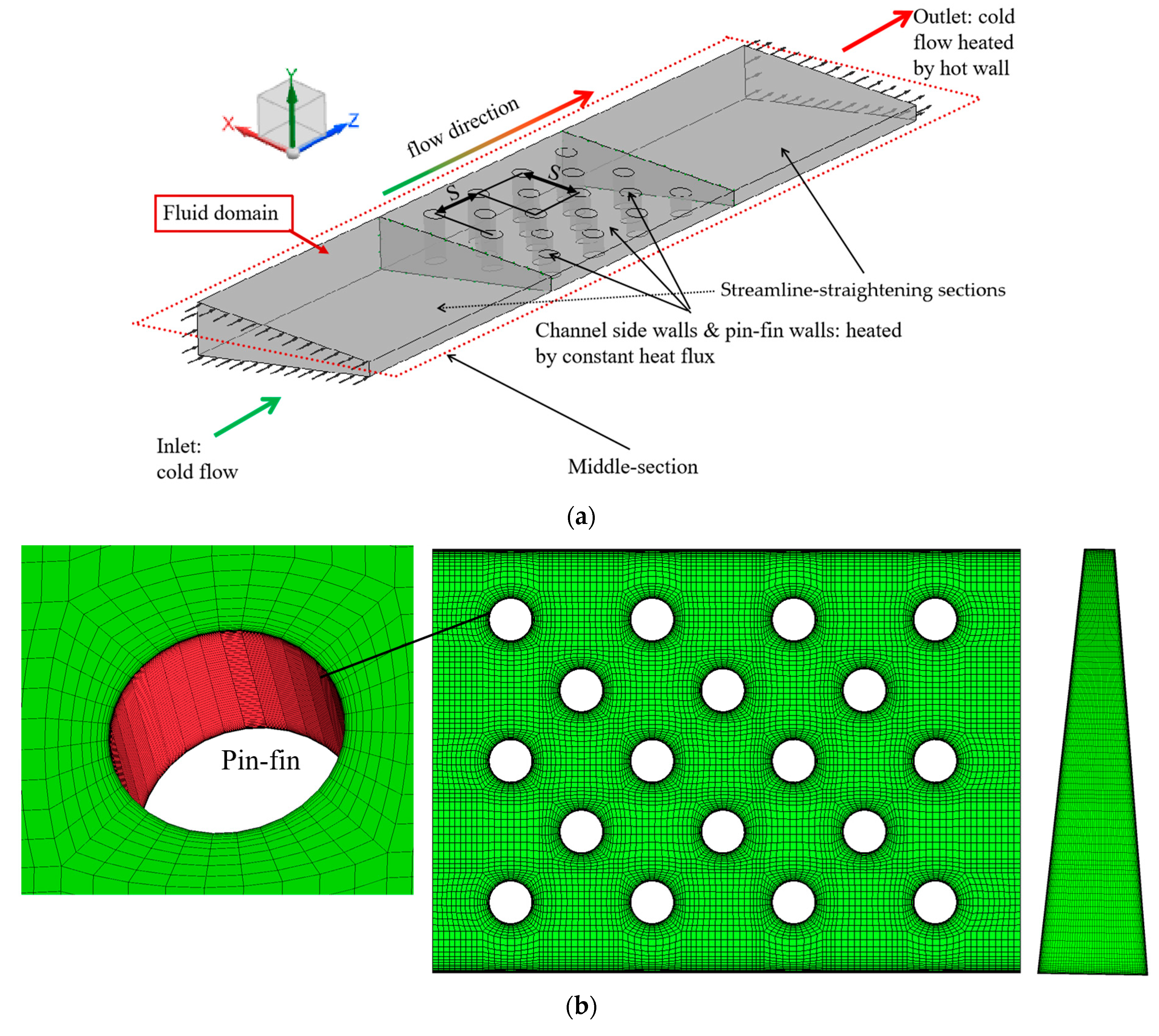
33] can be simplified as an isosceles trapezoidal channel, and its cooling effect is relatively poor, which is attributed to the absence of a cooling structure arrangement. The present study specifically focuses on addressing the issue of inadequate cooling performance and high thermal loads at the trailing edge of such turbine blades through numerical analysis. Herein, the SST k-ω turbulence model is proven reliable to predict the flow patterns and heat transfer characteristics of pin-fin-steam cooling structures. A relatively simple Pearson correlation coefficient method is utilized to derive the sensitivity coefficients of the average Nusselt numbers and friction factors concerning the input parameters. Initially, based on the geometrical characteristics of the turbine blade’s trailing edge, a physical model was developed for an isosceles trapezoidal channel with pin-fin arrays under steam cooling conditions. Subsequently, the combined influence laws of varying pairs of parameters such as Reynolds number (
Re = 10,000 to 50,000), dimensionless pin-fin diameter (
d/
H = 0.4 to 0.8), and dimensionless pin-fin spacing (
S/
H = 1.6 to 2.4) on the flow and heat transfer characteristics in the steam-cooled isosceles trapezoidal channel with pin-fin arrays were examined in depth. Then, sensitivity analysis was employed to determine the relative significance of these influence parameters on the cooling performance of the isosceles trapezoidal channel with pin-fin arrays. Finally, within the range of the investigated parameters, relevant heat transfer and friction correlations were fitted. The findings may offer valuable reference and guidance for the design of steam cooling configurations within the trailing-edge channels of high-temperature turbine blades in future advanced gas turbine cooling technology.
3. Verification of Numerical Calculation Methods
This paper utilizes the physical model and experimental data of the isosceles trapezoidal cooling channel with pin-fin structure reported by Hwang et al. [
37] to validate the numerical methods employed herein. The boundary conditions in the numerical simulations are consistent with those in the referenced experimental setup. Concerning the turbulence models, Li et al. [
38] evaluated the flow and heat transfer characteristics of pin-fin arrays within narrow channels using six turbulence models: RKE
k-ε, RNG
k-ε, SST
k-ω, BSL
k-ω, EARSM
k-ω, and V2F, comparing their predictions against experimental results. Their work indicated that the SST
k-ω turbulence model provides the most accurate and comprehensive predictions of the flow and heat transfer variations in the isosceles trapezoidal cooling channel with a pin-fin structure. Furthermore, Ref. [
37] also consistently demonstrates that the SST
k-ω turbulence model offers the most precise forecasts. Hence, this study adopts the SST
k-ω turbulence model for numerical computations.
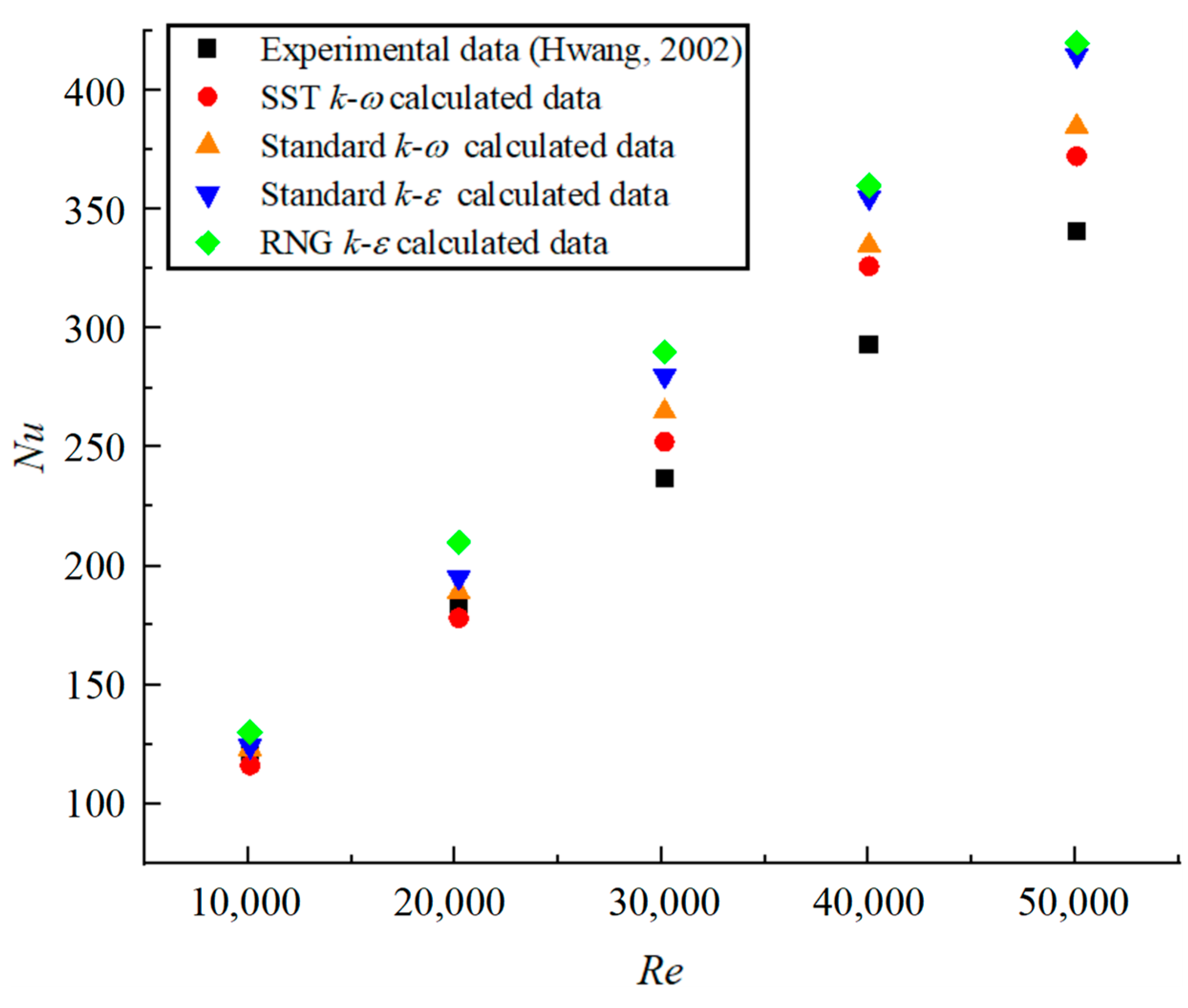
Figure 3 presents a comparison of the numerical results obtained in this study against the experimental findings reported in Ref. [
37]. As evidenced in
Figure 3, there is good agreement between the simulation outcomes and the experimental data using the SST
k-ω turbulence model, with the maximum deviation occurring at
Re = 40,000, where the discrepancy is 9.5%. For the standard
k-ω, standard
k-ε, and RNG
k-ε turbulence models, the numerical results of errors have a trend of increasing gradually. These findings substantiate that the numerical methods and turbulence model employed herein meet the precision requirements for simulating the cooling performance of the isosceles trapezoidal channel with pin-fin arrays at the trailing edge of gas turbine blades. Moreover, the deviations identified in the validation of the numerical method have been used as correction factors in subsequent calculations involving Nusselt numbers throughout this paper, thereby enhancing the accuracy of the numerical results.
4. Analysis and Discussion of Calculation Results
4.1. Flow Characteristics of Steam Cooling
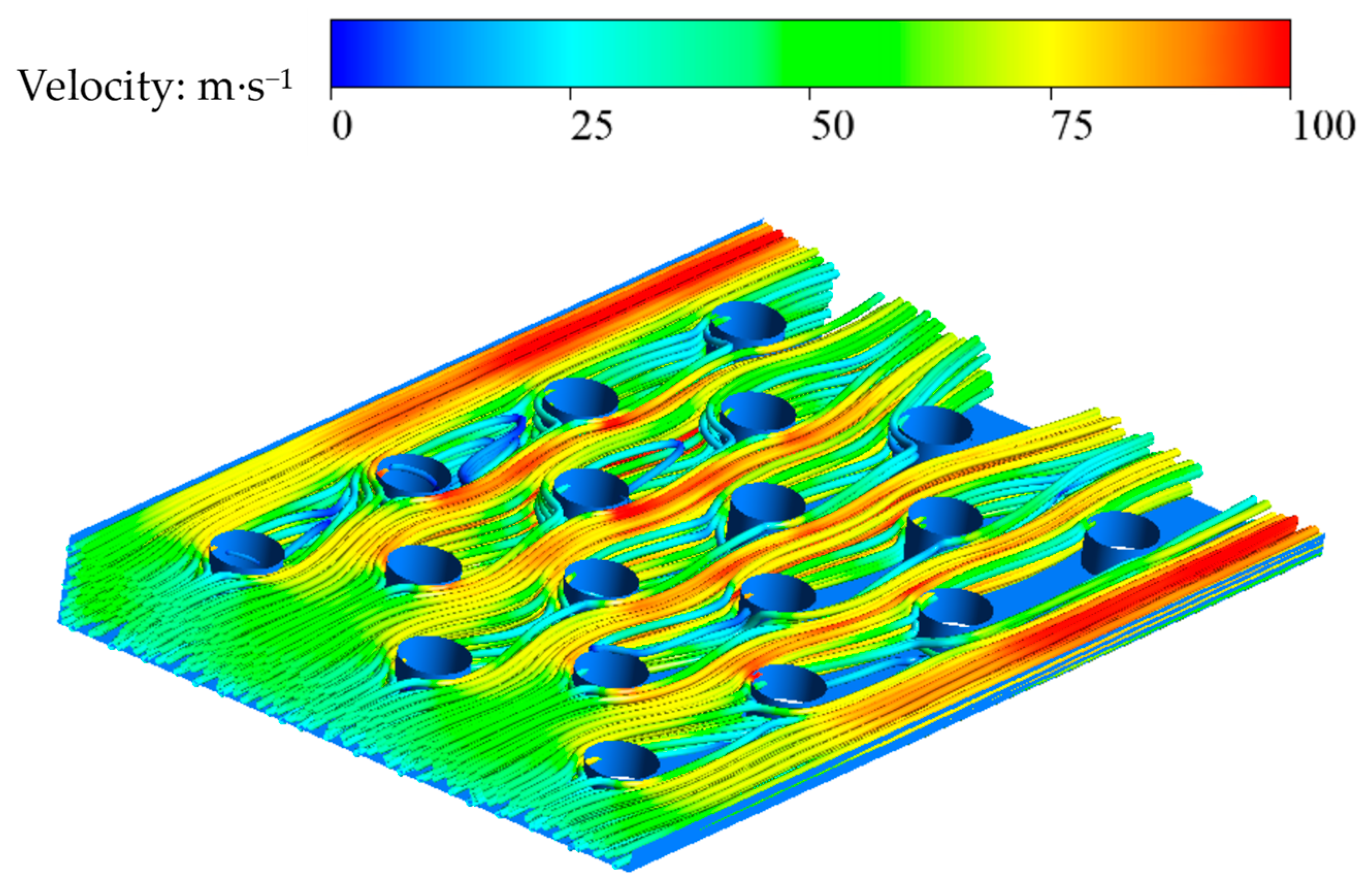
Figure 4 illustrates the three-dimensional flow field distribution in the isosceles trapezoidal cooling channel with pin-fin arrays at
Re = 30,000. As shown, the cooling steam enters the channel with a relatively uniform velocity, and upon encountering the first row of pin-fins, the steam flow separates at stagnation points along the leading edges of each pin-fin due to the obstruction caused by the pin-fins. The separated flow rapidly accelerates, forming horseshoe vortices around the pin-fins. Subsequently, substantial wake vortices develop immediately downstream of the pin-fins, where the flow velocity is notably lower. The presence of these wake vortices directly influences the upstream flow of the cooling steam over the succeeding rows of pin-fins. Owing to the nature of the isosceles trapezoidal cooling channel, with one side being wider and the other narrower, the separation points on the leading edges of each pin-fin tend to shift towards the narrower side of the channel. Since no pin-fins are arranged along the sides of the isosceles trapezoidal cooling channel, higher flow velocities are observed in these regions. Overall, within the isosceles trapezoidal cooling channel, the flow velocities are higher along the sides of the pin-fins, while the flow velocities of the cooling steam are lower in the upstream and downstream regions around the individual pin-fins.
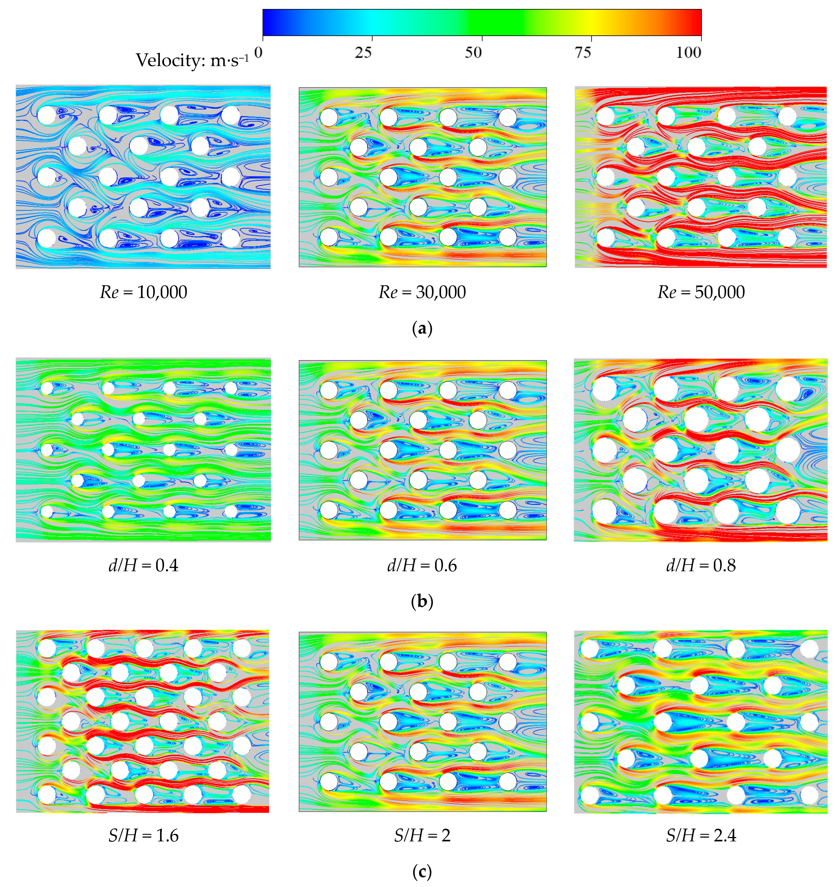
Figure 5 depicts the cross-sectional flow field distributions in the isosceles trapezoidal cooling channel with pin-fin arrays under different Reynolds numbers, dimensionless pin-fin diameters, and dimensionless pin-fin spacing. From
Figure 5a, it can be discerned that a pair of counter-rotating asymmetrical Von Karman vortices forms downstream of each pin-fin. As the Reynolds number increases, the size of these asymmetrical Von Karman vortices remains largely unchanged, yet their rotational velocity markedly increases, accompanied by a significant rise in the flow velocity of the cooling steam along the sides of the pin-fins. In
Figure 5b, it is evident that with an increase in dimensionless pin-fin diameter, the size of the asymmetrical Von Karman vortices downstream initially increases before decreasing. This phenomenon occurs because when the dimensionless pin-fin diameter is small, increasing its diameter intensifies the fluid disturbance, giving rise to larger asymmetrical Von Karman vortices downstream. However, when the dimensionless pin-fin diameter becomes large, the reduced spacing between the pin-fins restricts the development of these downstream vortices. Additionally, the enlargement of the dimensionless pin-fin diameter leads to a noticeable increase in the flow velocity alongside the pin-fins, attributed to the decreased flow area between the enlarged pin-fins. From
Figure 5c, it is clear that as the dimensionless pin-fin spacing increases, the asymmetrical Von Karman vortices downstream of the pin-fins become significantly larger. Concurrently, the flow velocity along the sides of the pin-fins initially rapidly decreases and then stabilizes. This is because when the dimensionless pin-fin spacing is small, more pin-fins can be accommodated, leading to a smaller inter-pin-fin flow area and therefore higher cooling steam velocity. On the other hand, when the dimensionless pin-fin spacing is increased, the asymmetrical Von Karman vortices downstream are allowed to develop more fully, subsequently growing in size.
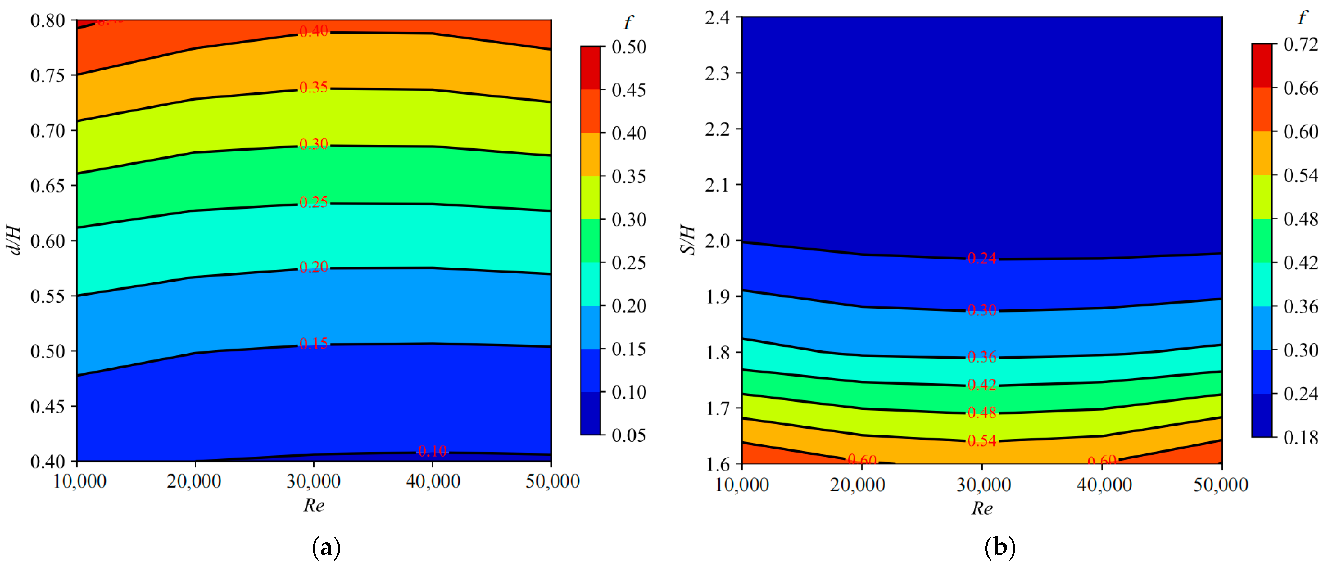
Figure 6 presents the variation curves of the friction factor for the isosceles trapezoidal cooling channel with pin-fin arrays as a function of dimensionless pin-fin diameter and dimensionless pin-fin spacing. Evidently, the change in the Reynolds number exerts a minor influence on the friction factor in the isosceles trapezoidal cooling channel with pin-fin arrays. As
Figure 6a shows, the friction factor of the isosceles trapezoidal cooling channel with pin-fin arrays increases sharply with the enlargement of the dimensionless pin-fin diameter, and this rate of increase progressively accelerates. This is because a larger dimensionless pin-fin diameter introduces stronger disturbances to the fluid within the channel, generating larger asymmetrical Von Karman vortices downstream that contribute to a greater friction factor. Additionally, the increase in dimensionless pin-fin diameter reduces the flow area in the channel, thereby augmenting the flow velocity along the sides of the pin-fins, which in turn heightens the friction factor within the channel. Calculations reveal that when the dimensionless pin-fin diameter increases from 0.4 to 0.8, the friction factor of the isosceles trapezoidal cooling channel with pin-fin arrays rises by approximately 3.25 to 3.41 times across various Reynolds numbers.
Figure 6b demonstrates that for the value of dimensionless pin-fin spacing less than 2.0, the friction factor of the isosceles trapezoidal cooling channel with pin-fin arrays decreases rapidly as the dimensionless pin-fin spacing increases. When the value of dimensionless pin-fin spacing is greater than 2.0, the friction factor either decreases slowly or remains steady. This behavior is attributed to the initial significant decline and subsequent insignificant change in the flow velocity along the sides of the pin-fins as the dimensionless pin-fin spacing grows. It is noteworthy that, as calculated, when dimensionless pin-fin spacing increases from 1.6 to 2.4, the friction factor of the isosceles trapezoidal cooling channel with pin-fin arrays drops by approximately 67.38% to 69.18% across different Reynolds numbers.
4.2. Heat Transfer Characteristics of Steam Cooling
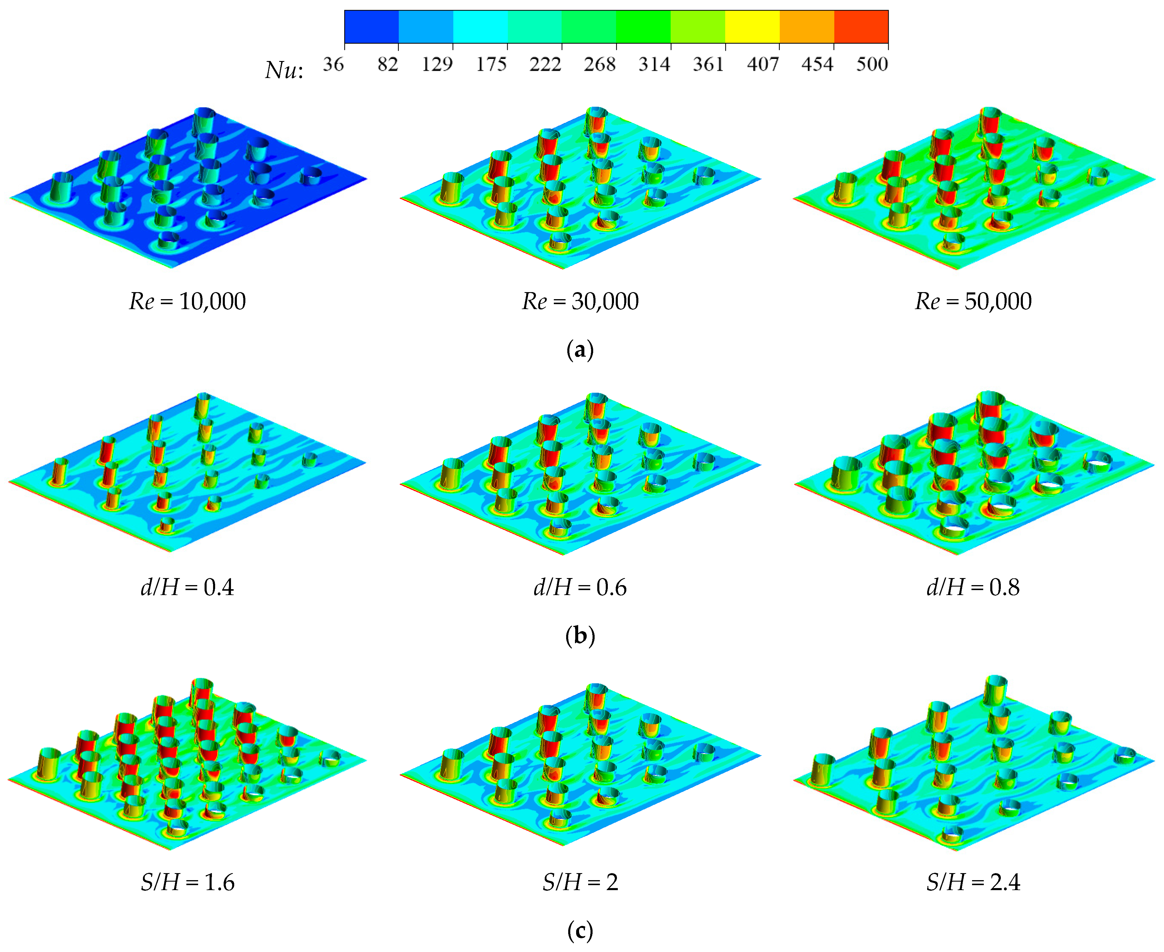
Figure 7 presents contour maps of the Nusselt number distribution on the channel wall and pin-fin wall of the isosceles trapezoidal cooling channel with pin-fin arrays under various study parameters. As per the figure, due to the presence of horseshoe vortices around the pin-fins, high heat transfer zones in the shape of horseshoes form upstream and on both sides of each pin-fin on the channel wall. Conversely, the downstream area of the pin-fins experiences a sharp decline in heat transfer due to the existence of wake vortices. Regarding the pin-fin wall, the windward face experiences a high heat transfer coefficient as it is directly impacted by the cooling steam flow. This coefficient rapidly decreases along the circumference towards the leeward side, reaching its lowest point at the backside of the pin-fin. Notably, the unequal width of the sidewalls in the isosceles trapezoidal cooling channel results in a higher flow velocity of the cooling steam near the narrower sidewall. Consequently, the high heat transfer region on the windward face of the pin-fin shifts towards the narrower sidewall. As seen in
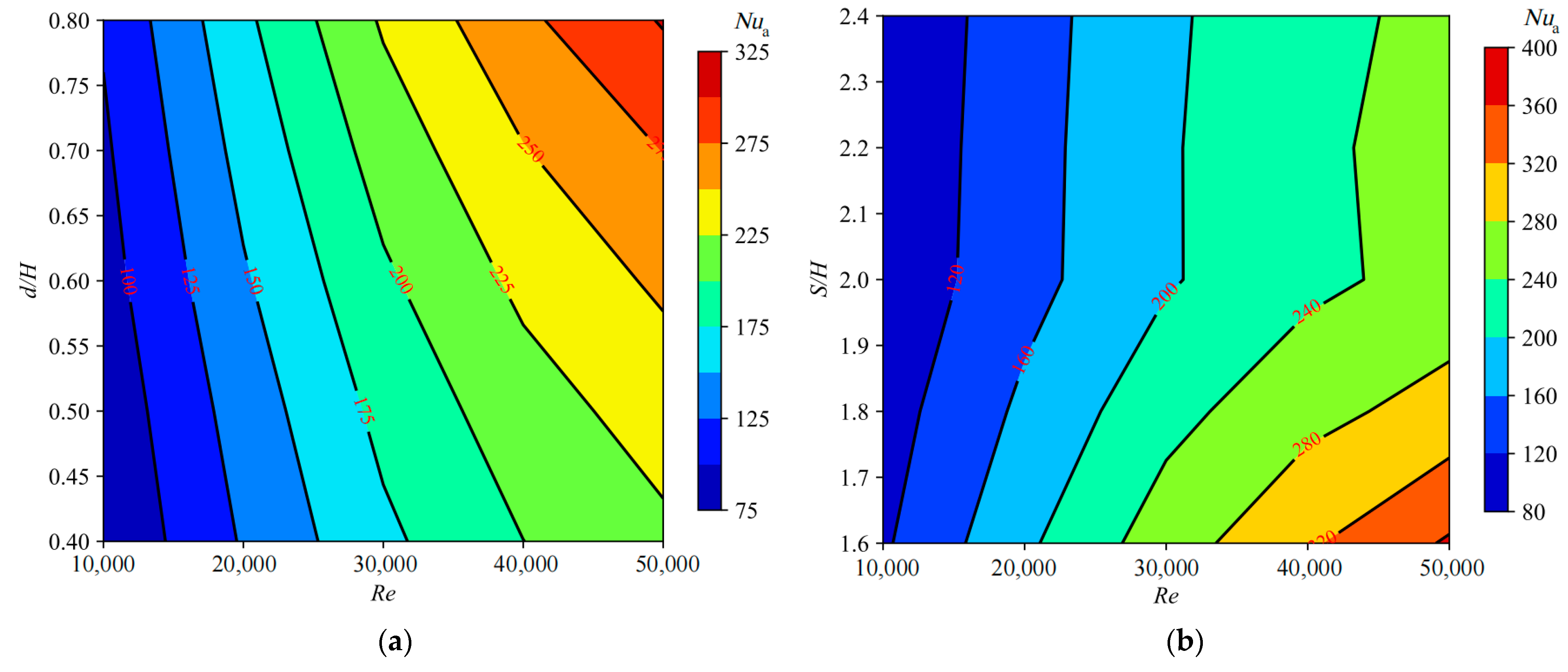
Figure 7a, with the increase in the Reynolds number, both the Nusselt numbers on the channel wall and the pin-fin wall show a marked enhancement. This is because an increase in the Reynolds number corresponds to a rise in the cooling steam velocity, resulting in intensified turbulent flow interactions with the pin fins, which in turn strengthens the heat transfer effects on the channel wall and pin-fin wall. From
Figure 7b, it is evident that an increase in the dimensionless pin-fin diameter leads to a more effective enhancement of the heat transfer performance on both the channel wall and the pin-fin wall, particularly pronounced on the windward face of the pin-fins. This heightened heat transfer is attributed to the decrease in the flow area within the channel brought about by the larger pin-fin diameter, causing an increase in the cooling steam velocity and thereby intensifying the heat transfer within the channel. In
Figure 7c, the widening of the pin-fin spacing causes a noticeable reduction in the Nusselt numbers on both the channel wall and the pin-fin wall, with a more significant decline observed on the pin-fin wall. This reduction occurs due to the increased flow area within the channel accompanying larger pin-fin spacings, which results in a decrease in the cooling steam velocity and diminishes the overall heat transfer performance.
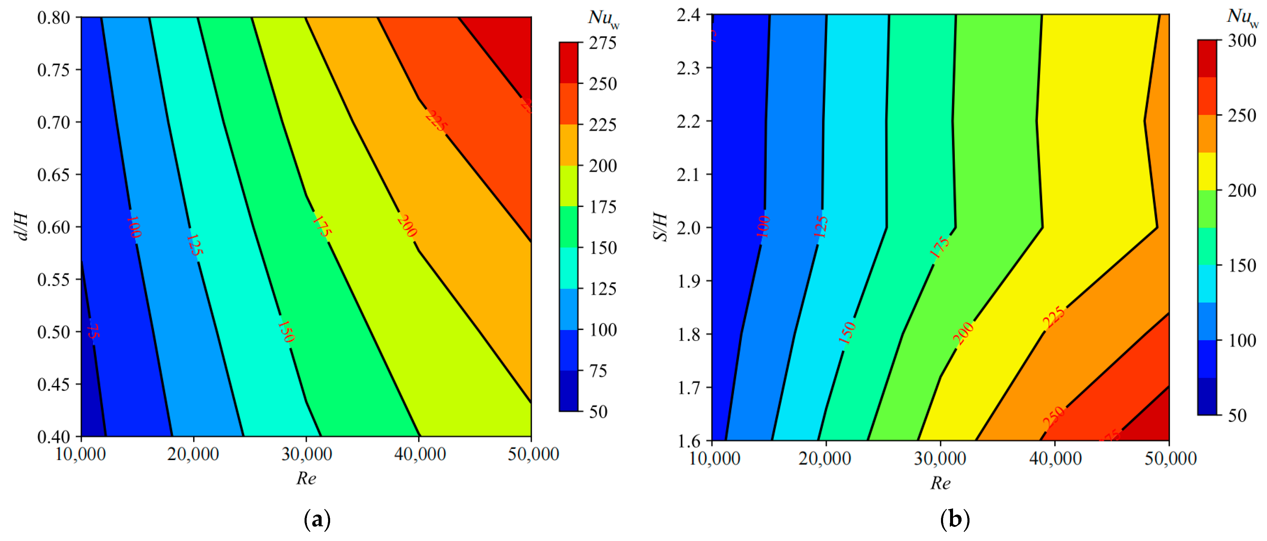
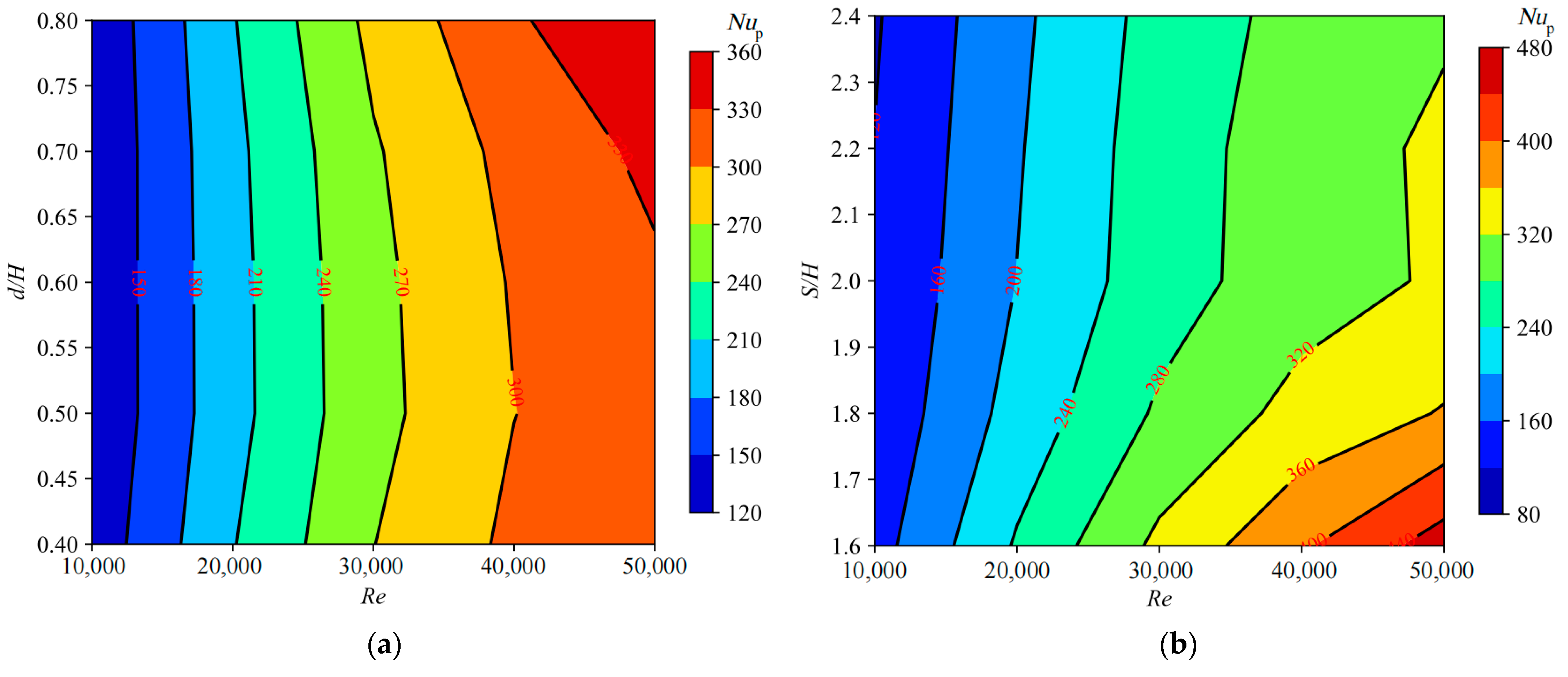
Figure 8,
Figure 9 and
Figure 10 present the curves depicting the variations of the channel wall average Nusselt number, pin-fin wall average Nusselt number, and overall average Nusselt number as functions of the dimensionless pin-fin diameter and dimensionless pin-fin spacing. From
Figure 8,
Figure 9 and
Figure 10, it is discernible that, aside from the variation trend of the pin-fin wall average Nusselt number with respect to the dimensionless pin-fin diameter, the trends of channel wall average Nusselt number, pin-fin wall average Nusselt number, and overall average Nusselt number with respect to the Reynolds number, dimensionless pin-fin diameter, and dimensionless pin-fin spacing are generally consistent. Namely, they all increase with rising Reynolds numbers, albeit with diminishing increments, gradually increase with larger dimensionless pin-fin diameters, and initially rapidly decrease and then slowly decrease or remain relatively constant as the dimensionless pin-fin spacing widens. For the variation trend of the pin-fin wall average Nusselt number with respect to the dimensionless pin-fin diameter, as shown in
Figure 9a, it exhibits a trend of initially decreasing and subsequently increasing, with this phenomenon being more pronounced at larger Reynolds numbers. Additionally, it is observed that the effects of dimensionless pin-fin diameter and dimensionless pin-fin spacing on channel wall average Nusselt number, pin-fin wall average Nusselt number, and overall average Nusselt number are more pronounced at higher Reynolds numbers. Moreover, it is revealed that the heat transfer performance on the pin-fin wall is consistently superior to that on the channel wall, with the average Nusselt number on the pin-fin wall being approximately 1.3 times that of the channel wall average Nusselt number. Through calculations, it is determined that, under different Reynolds numbers, when the dimensionless pin-fin diameter increases from 0.4 to 0.8, the channel wall average Nusselt number, pin-fin wall average Nusselt number, and overall average Nusselt number, respectively, increase by approximately 36.35% to 38.24%, 0.16% to 11.33%, and 31.05% to 37.41%. Meanwhile, when the dimensionless pin-fin spacing increases from 1.2 to 2.4, the channel wall average Nusselt number, pin-fin wall average Nusselt number, and overall average Nusselt number, respectively, decrease by approximately 19.12% to 23.16%, 19.60% to 31.30%, and 24.95% to 31.14%, for the isosceles trapezoidal cooling channel with pin-fin arrays.
4.3. Integrated Thermal-Hydraulic Performance of Steam Cooling
Figure 11 presents the variation curves of the integrated thermal-hydraulic performance factor of the isosceles trapezoidal cooling channel with pin-fin arrays with changing dimensionless pin-fin diameter and dimensionless pin-fin spacing at different Reynolds numbers. It is worth noting that the integrated thermal-hydraulic performance factor is computed based on the overall average Nusselt number across the entire heat transfer surface. From the figure, it can be deduced that the integrated thermal-hydraulic performance factor of the isosceles trapezoidal cooling channel with pin-fin arrays declines almost proportionally with an increase in the Reynolds number. Although the overall average Nusselt number and friction factor of the isosceles trapezoidal cooling channel with pin-fin arrays both increase with a rise in the dimensionless pin-fin diameter and decrease with an increase in the dimensionless pin-fin spacing, the channel’s integrated thermal-hydraulic performance factor exhibits an opposing trend to these changes. Upon calculation, it is found that within the studied parameter range, the integrated thermal-hydraulic performance factor decreases by approximately 16.22% to 19.09% with an increase in dimensionless pin-fin diameter, and conversely, it improves by about 1.95% to 9.03% with an increase in dimensionless pin-fin spacing.
Compared with existing literature [
27,
28], the present study investigates a much wider range of conditions and structural parameters of a pin-fin cooling trapezoidal channel with steam coolant. A comprehensive analysis is conducted to reveal the effect of pin-fin on heat transfer and friction loss characteristics of the cooling channel, providing excellent choices for pin-fin cooling structure design of the trailing edge of the blade.
4.4. Parameter Sensitivity Analysis for Steam Cooling
Sensitivity analysis is a method employed to investigate the extent to which changes in input parameters (influence parameters) affect output parameters (performance parameters). Through sensitivity analysis, the relative importance of each input parameter to the output parameter can be quantified, where a larger sensitivity coefficient signifies a more critical input parameter. Since the variations of the average Nusselt numbers, friction factors, and integrated thermal-hydraulic performance factors for the isosceles trapezoidal cooling channel with pin-fin arrays at the trailing edge follow relatively simple patterns with respect to changes in the Reynolds number, dimensionless pin-fin diameter, and dimensionless pin-fin spacing. Therefore, a relatively simple Pearson correlation coefficient method can be utilized to derive the sensitivity coefficients of the average Nusselt numbers and friction factors concerning the input parameters [
39]. This enables a qualitative assessment of the significance of each influence parameter. The formula for calculating the Pearson correlation coefficient [
40] is as follows:
where
σi and
σy represent the standard deviations of variables
xi and
y, respectively [
41].
The procedure of the Pearson correlation coefficient method is shown as follows:
Step 1: prepare a dataset of the influence parameters (Re, d/H, and S/H) and the performance parameters (Nuw, Nup, Nua, f, and F);
Step 2: calculate the average value for each influence parameter (Re, d/H, and S/H) and the performance parameters (Nuw, Nup, Nua, f, and F);
Step 3: calculate the orthorhombic deviation for each pair of influence parameters and the performance parameters, such as the average value of Re·Nuw;
Step 4: now, using the average values of each influence parameter (Re, d/H, and S/H) and the performance parameters (Nuw, Nup, Nua, f, and F) to obtain their standard deviation;
Step 5: finally, by calculating the Pearson correlation coefficient and based on this value, relevance degrees of each influence parameter (Re, d/H, and S/H) for each performance parameter (Nuw, Nup, Nua, f, and F) are obtained. PEAR(xi) < 0 means negative correlation, while PEAR(xi) > 0 means positive correlation, and PEAR(xi) = 0 means no correlation between two parameters.
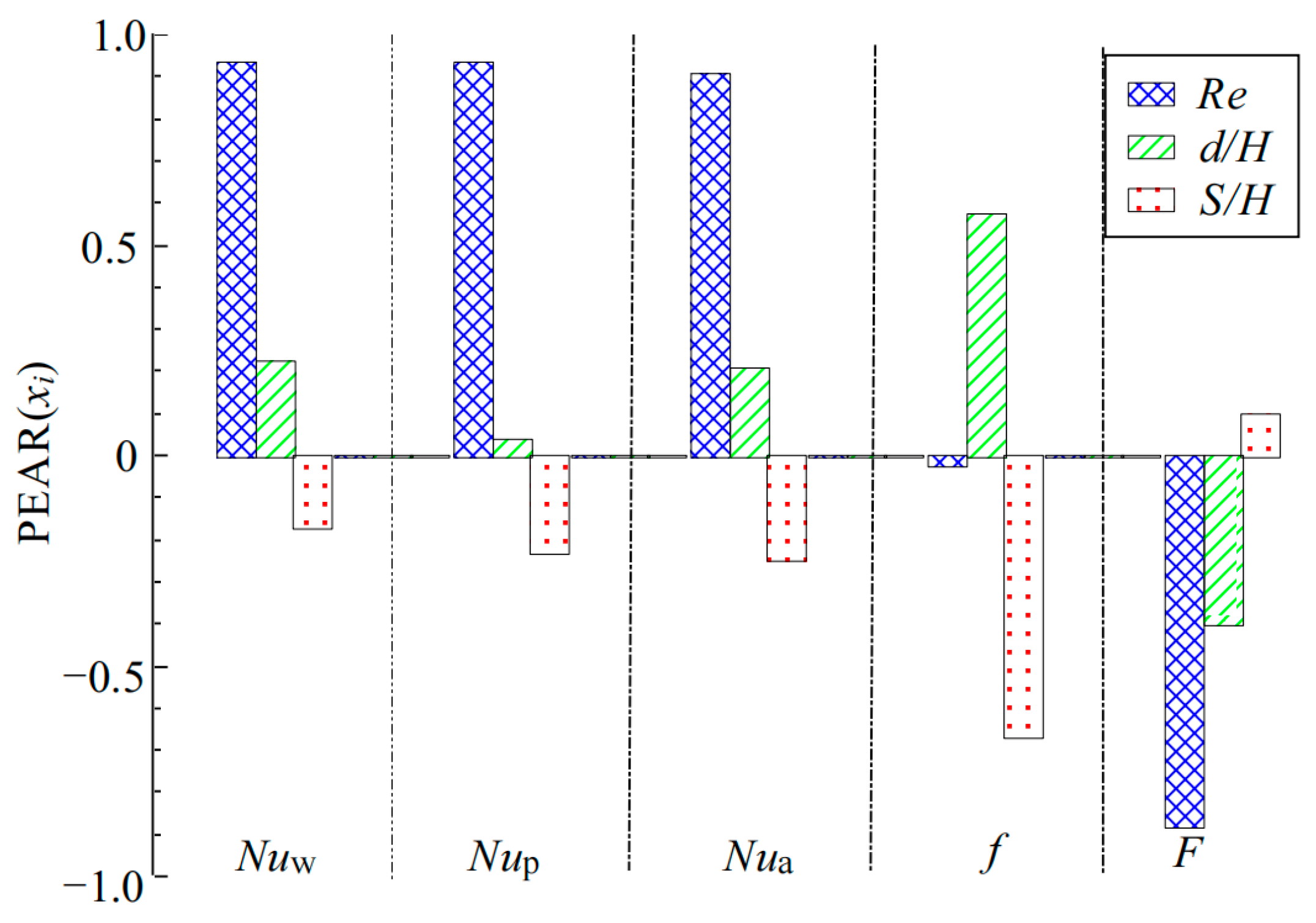
Figure 12 presents the sensitivity relationships between the influence parameters
Re,
d/
H, and
S/
H and the performance parameters
Nuw,
Nup,
Nua,
f and
F. The figure reveals that the Reynolds number has a more pronounced effect on the channel wall average Nusselt number, pin-fin wall average Nusselt number, and overall average Nusselt numbers, as well as the integrated thermal-hydraulic performance factor, compared to the structural parameters of the dimensionless pin-fin diameter and dimensionless pin-fin spacing. Conversely, its influence on the friction factor is less significant than that of the dimensionless pin-fin diameter and dimensionless pin-fin spacing. This is because when the Reynolds number increases, the pressure drop across the channel inlet and outlet, along with the square of the inlet cooling steam velocity, also increases, which results in only a slight change in the friction factor. Regarding the structural parameters’ impact on the heat transfer performance, the dimensionless pin-fin diameter has a greater influence on the channel wall average Nusselt number than the dimensionless pin-fin spacing does, but it exerts a lesser influence on the pin-fin wall average Nusselt number than the dimensionless pin-fin spacing, leading to a marginal difference between the effects of dimensionless pin-fin diameter and dimensionless pin-fin spacing on the overall average Nusselt number.
In terms of the structural parameters’ impact on fluid flow performance, the dimensionless pin-fin diameter has a lesser impact on the friction factor than the dimensionless pin-fin spacing. With respect to the structural parameters’ impact on the integrated thermal-hydraulic performance, the dimensionless pin-fin diameter has a more significant effect on the integrated thermal-hydraulic performance factor than the dimensionless pin-fin spacing. Furthermore, the dimensionless pin-fin diameter displays a positive correlation with both the average Nusselt number and friction factor, while exhibiting a negative correlation with the integrated thermal-hydraulic performance factor. In contrast, the dimensionless pin-fin spacing displays a negative correlation with both the average Nusselt number and friction factor, while exhibiting a positive correlation with the integrated thermal-hydraulic performance factor. In summary, when seeking to enhance heat transfer performance, both the dimensionless pin-fin diameter and dimensionless pin-fin spacing are equally important. To minimize the flow pressure drops, the dimensionless pin-fin spacing should receive particular attention. When considering the integrated thermal-hydraulic performance, special emphasis should be placed on the influence of the dimensionless pin-fin diameter.
4.5. Correlation Fitting for Steam Cooling
Heat transfer and friction correlations of the trailing-edge isosceles trapezoidal cooling channel with pin-fin arrays play a pivotal role in guiding the design of steam cooling structures for heavy-duty gas turbine blades in future applications. Based on the analyses in
Section 4.1,
Section 4.2,
Section 4.3, it is evident that the channel wall average Nusselt number, pin-fin wall average Nusselt number, overall average Nusselt number, and friction factor monotonically increase with increasing dimensionless pin-fin diameter and decrease with increasing dimensionless pin-fin spacing for the trailing-edge isosceles trapezoidal cooling channel with pin-fin arrays. Concurrently, the channel wall average Nusselt number, pin-fin wall average Nusselt number, and overall average Nusselt number exhibit monotonic increases with increasing Reynolds number, whereas the friction factor undergoes minimal change as Reynolds number increases. Therefore, it is reasonable to hypothesize that the correlations between performance parameters
Nuw,
Nup,
Nua, and
f and the influence parameters
Re,
d/
H, and
S/
H can be represented by multiplying power functions, formulated as:
where,
f(
x) represents the performance parameters
Nuw,
Nup,
Nua, and
f, while
x1,
x2, and
x3 represent the influence parameters
Re,
d/
H, and
S/
H, respectively.
The correlation fitting work is completed by the curve fit module of the Scipy package in Python 3.8 through self-programming via the Python language, which only requires calling the cooling data table in CSV format and running the code to generate a table file containing fitting coefficients. Based on the dataset from the research, empirical correlations reflecting the influence of Reynolds number, dimensionless pin-fin diameter, and dimensionless pin-fin spacing on the channel wall average Nusselt number, pin-fin wall average Nusselt number, overall average Nusselt number, and friction factor of the trailing-edge isosceles trapezoidal cooling channel with pin-fin arrays were derived using the method of multiple linear regression. The fitting coefficients for each correlation are tabulated in
Table 2, and these correlations are applicable within the following ranges: 10,000 ≤
Re ≤ 50,000, 0.4 ≤
d/
H ≤ 0.8, and 1.6 ≤
S/
H ≤ 2.4.
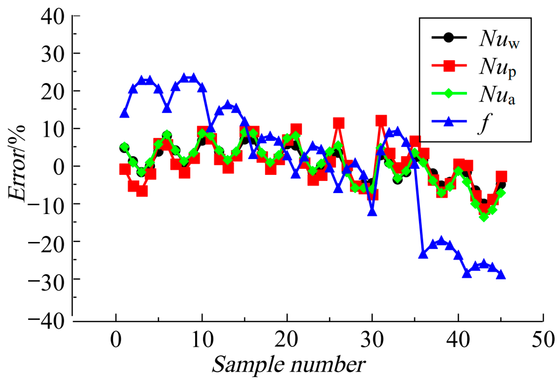
Figure 13 presents the distribution of fitting errors for the empirical correlations. The plot reveals that the fitting errors for all heat transfer correlations fall within ±15%, with the maximum error for the correlation of channel wall average Nusselt number being −9.98% and an average error of 0.54%; the highest error for the correlation of pin-fin wall average Nusselt number is 12.17% and an average error of 0.70%; and the peak error for the correlation of overall average Nusselt number amounts to −13.42% with an average error of 0.52%. For the correlation of the friction factor, the maximum error is −28.16% and the average error is 0.30%. The average fitting errors for all empirical correlations are less than 1%, which attests to the reasonableness of the error distribution. Therefore, the heat transfer and friction correlations derived in this study can accurately predict the channel wall average Nusselt number, pin-fin wall average Nusselt number, and overall average Nusselt number, as well as the friction factor, for the isosceles trapezoidal cooling channel with pin-fin arrays at the trailing edge of gas turbine blades, given their low average fitting errors. These correlations may provide valuable reference and insight for the design of steam cooling structures in the trailing-edge channels of advanced gas turbine high-temperature blades.
As shown in
Figure 1, the tailing edge of the blade is simplified as an isosceles trapezoidal cooling channel with pin-fin arrays, which means that the correlations derived can be used to estimate the cooling performance of the tailing-edge area of turbine blades. In this way, experimental research costs will be reduced in order to design a high-efficiency cooling structure for blades.

