Abstract
The process of impinging-jet atomization involves the collision of multiple liquid jets to create atomization. This study specifically focuses on a system that utilizes impinging atomization with multiple jets. The injectors used in this study are arranged in either a planar configuration for doublet injectors or a stereoscopic configuration for quadruplet injectors, both designed to facilitate impinging atomization. The angle at which the jets collide is set at 90°, with injector intersection angles of either 60° or 120°. The diameter of the jets ranges from 0.8 to 1.1 mm, while the length–diameter ratio of the pipe remains fixed at 10. To investigate the atomization process, experiments were conducted by varying flow rates (ranging from 30 to 130 mL/min) from each injector using pure water as the working fluid. This resulted in a range of Weber numbers spanning from 4 to 206 and Reynolds numbers ranging from 578 to 3443. Four atomization regimes were observed in the impinging atomization flow field: closed-rim mode, periodic drop mode, open rim mode, and fully developed mode. The experiment utilized a high-speed camera to observe the formation and breakup of the liquid sheet. However, increasing the number of jets and altering the impingement configuration had minimal impact on the liquid sheet patterns as the Weber number increased. Compared to traditional double jet atomization, quadruplet jet atomization resulted in the wider extension of liquid sheets and similar atomization patterns. This study is useful for designing jet impingement-atomization systems for confined spaces.
1. Introduction
Spray and atomization are commonly employed in various industry applications, including printing [1], combustion [2], drying [3], and agriculture [4]. Among the different techniques for liquid-jet breakup, jet impact atomization stands out due to its simplicity and cost-effective manufacturing process that guarantees efficient atomization. This method has proven successful in liquid rocket engines and engine combustion systems [5]. Rupe [6] conducted a study on liquid injectors for impingement atomization, focusing on the characteristics and effects of momentum ratio and impingement angle. Heidmann et al. [7] identified four breakup regimes for impinging jets: closed rim, periodic rim, open rim, and fully developed. They concluded that variations in jet diameter and length before impingement had minimal impact on the wave frequency. Taylor [8] conducted a study on impinging water jets to analyze the thickness and shape of liquid sheets. The observed sheets in these experiments resembled the closed rim and periodic rim previously reported by Heidmann et al. [7]. Based on these findings, predictions were made regarding the shape of a leaf-like sheet with a thicker boundary. Further research by Dombrowski and Hooper [9] revealed that the breakup of the liquid sheet is caused by the interaction between aerodynamics and hydrodynamics, resulting in ripples on its surface. These ripples are only generated near the point of impact at higher jet speeds and collision angles. In scholarly research, investigators have conducted experimental and theoretical studies on double-impinging-liquid films, exploring dynamic characteristics such as liquid-film thickness, dimensions, and interfacial velocities [10,11,12,13].
Besides water, liquids with different viscosities have also been used to study impingement atomization due to the significant impact that viscosity has on atomization characteristics. Chojnacki and Feikema [14] studied the atomization of gelled propellants through jet impingement for propulsion applications. The findings revealed that, within the range of a Weber number (We) between 400 and 500, the liquid sheets started to fragment into ligaments but faced challenges to further fragmentation into droplets. Kang et al. [15] conducted experiments on the liquid sheet of doublet-impinging jets. The results revealed that as the impingement velocity increased, both the thickness and maximum length of the liquid sheet also increased. However, changes in angle did not significantly impact the thickness or maximum length of the liquid sheet when the impingement angle exceeded 120°. Based on the studies conducted on double-jet atomization by Lai et al. [16,17], it was found that the average droplet size decreased rapidly with an increase in impingement velocity within a specific range. Furthermore, factors such as impingement distance and the angle between the two jet streams also influenced the characteristics of the spray. Inamura and Shirota [18] conducted a study on the effect of velocity profiles of double impinging jets on the formation of liquid sheets. They discovered that when the velocities of both jets were equal, the liquid sheet became flatter and had a more uniform thickness. Li and Ashgriz [19] investigated liquid sheet breakup, noting closed-rim sheets with Weber numbers below 150. They observed a linear relationship between breakup length/width and the Weber number of individual jets. The experimental results aligned well with theoretical predictions, indicating the model’s capability to estimate maximum length and average thickness of a liquid sheet. Soni et al. [20] found that the ejection of the droplets stabilizes the rim by shedding the kinetic energy through the droplets, thus ensuring that the liquid rim remains quasi-stable without any disintegration. Plateau–Rayleigh instability is the main reason for the formation of droplets through fingering instability and significantly contributes to the atomization regime. Previous research focused on investigating oblique cylindrical jet collisions through experiments. The parameters for double-jet atomization from the literature are summarized in Table 1.
Improving atomization for smaller droplets can reduce fuel consumption and advance propulsion technology, and a multiple-nozzle spray system can achieve higher uniformity and spray efficiency Panão and Delgado [21]. Furthermore, the choice of nozzle diameter and spacing has the most significant impact on spray performance. Avulapati and Rayavarapu Venkata [22] conducted a study on atomization, specifically focusing on the configuration where a gas jet is directed onto the impinging point of two liquid jets. Their findings indicate that surface tension does not have a significant impact on the spray structure in this mode of atomization. They observed that at low liquid-jet velocity, atomization occurs in the prompt mode, while at higher velocities, it shifts to the classical mode. Furthermore, their results demonstrate that changes in the angle between liquid jets do not significantly affect the breakup phenomenon. Panão and Delgado [23] investigated the atomization of doublet- and triplet-impinging jets. The results showed that droplet properties in sprays created by both types of jets were similar. However, the influence of geometric factors resulting from the impingement angle was more pronounced in the spray produced by triplet impinging jets. Baek and Han [24] conducted numerical simulations of liquid sheets in the injection process using doublet and triplet injectors. They found that atomization through multiple-nozzle impingement can generate liquid chains and fish-bone structures. Kebriaee and Kazemi [25] investigated the impact of the Reynolds number (Re = 1000–11,000) on liquid sheet properties. They used a high-speed shadowgraph to capture images of the atomized region. The results showed that as the Reynolds number increases, both the length and width of the liquid sheet formed by triplet jets increase, along with an increase in the number of droplets.
Although many studies have been conducted on impinging-jet atomization, there is limited research on atomization of more than two impinging jets. As summarized in Table 2, studies often used atomization at impinging angles of 60, 90, and 120 degrees with water being the most employed working fluid. However, there was no relevant literature on the atomization process using triplet or quadruplet jets in a stereoscopic three-dimensional manner. This study explores 3D atomization with quadruplet jet impingement and examines the effects of jet diameter, velocity, and impingement angle. A high-speed camera captured images of planar doublet jets and non-planar quadruplet jets to analyze liquid sheet characteristics.


Table 1.
Doublet jets’ impingement-atomization-literature collation.
Table 1.
Doublet jets’ impingement-atomization-literature collation.
| Author | Fluid | (mm) | 2θ (Degree) | (mm) | L (mm) | (m/s) |
|---|---|---|---|---|---|---|
| Rupe [6] | Water/CCl4 | 6.35 | 0~150 | 3.175~6.35 | — | — |
| Heidmann, Priem and Humphrey [7] | Water/Glycerol | — | 30~100 | 0.635~1.45 | 50.8 | 6.1~24.4 |
| Taylor [8] | Water | — | 60~120 | 2.27 | 100 | 4.1, 5.6 |
| Dombrowski and Hooper [9] | Water/Nigrosine | 0.2 | 50~140 | 0.5 | 200 | 1.16~7.3 |
| Ibrahim and Przekwas [11] | Water | — | — | — | — | — |
| Ryan, Anderson, Pal and Santoro [13] | Water | — | 60 | 0.64, 0.51 | 25 | 6.4~18.5 |
| Chojnacki and Feikema [14] | Water/C941Carbopol | — | 180 | 3.81 | 381 | 3~18 |
| Lai, Huang and Jiang [16] | Water | 5 | 60~120 | 0.3 | 30 | 1.7~13 |
| Lai, Huang, Jiang and Huang [17] | Glycerol-water (Water, Sugar, Alcohol) | — | 90 | 0.5 | 50 | 1.7~20 |
| Li and Ashgriz [19] | Water | — | 60~120 | 0.4 | 64 | 1.86~8.75 |
| Bremond and Villermaux [26] | Water/Ethanol | — | 58~117 | 1.05, 1.42 | — | 1.5~4.6 |
| Lee et al. [27] | Water/Carbopol | 5 | 60 | 0.5 | 2.5, 10 | — |
| Baek et al. [28] | Water/C934Carbopol/SUS304 | — | 90 | 0.7 | 7 | 3.7~62.3 |
| Panão and Delgado [29] | Water | 2.5~7.5 | — | 1 | — | — |
| Bai et al. [30] | WaterC934Carbopol/NaOH | 7 | 60~105 | 0.7, 0.6, 0.6 × 1.2 | 2.5 | — |
| Inamura and Shirota [18] | Water | 10 | 60~150 | 1.1, 1.6 | 1.85, 5.3 | 1.88~20.2 |
| Ma et al. [31] | Water/C934Carbopol/NaOH | — | 90 | 0.6 | 10.3 | — |
| Zhao et al. [32] | Water/Kerosene /Glycerol-water | — | 60, 80 | 0.8, 0.6 | 8, 6 | 5.32~7.25 |
| Deng et al. [33] | Water/C934Carbopol | 15 | 45~90 | 0.6 | — | 22.9–39.4 |
| Kashanj and Kebriaee [34] | Glycerol-water | 3 | 90 | 0.61 | — | — |
| Indiana et al. [35] | Water/Alcohol | — | 45~75 | 0.51 | — | — |
| Deng et al. [36] | Nano-SiO2water-based gel simulant | 0~20 | 30~90 | 0.6 | — | 1.4~38.77 |

Table 2.
More than doublet jets’ impingement-atomization-literature collation.
2. Experimental Setup and Diagnostics
2.1. Experimental Setup and Measurement Techniques
This experiment involved constructing a 3D design with multiple jets for atomization, as shown in Figure 1. The aim of this study was to investigate the parameters that affect the atomization process, including the impinging angle (), jet velocity (), jet diameter (), position angle (), full angle (), maximum length of the liquid sheet (), and maximum width of the liquid sheet (). The spray-generation device used in this experiment utilized pure water as the working fluid, and its schematic is presented in Figure 2. A 20 L water tank stored pressurized water, equipped with a pressure gauge and pressure-release valve. Compressed air from an air compressor pressurized the water in the tank. This process was monitored using an air flow meter (ALICAT, PCD-100PSI Series) to maintain a pressure of 38 psi. The flow rate from the tank to the nozzle was controlled with a needle valve. Pressure gauges and a turbine flow meter were employed to monitor pipeline pressure and water flow rate, respectively, enabling independent control over each nozzle’s flow rate. The nozzles were made of brass with orifice diameters of 1.1 mm and 0.8 mm (), and the length-to-diameter ratio (L/) was maintained at 10. The pre-impact length, or the distance between the orifice outlet and impact point, was consistently set at 6.5 mm for all experiments. Careful adjustments were made to ensure that doublet- or quadruple-impinging-jet planes intersected each other by properly adjusting injector mounting components. This configuration can ensure a symmetrical liquid surface perpendicular to the impinging-jet plane.
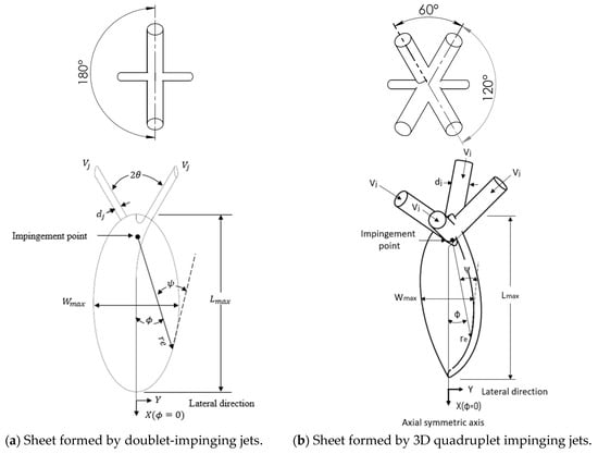
Figure 1.
Sketch of liquid sheet formed by impinging jets.
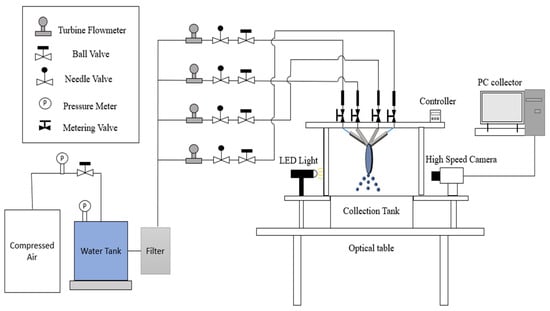
Figure 2.
Experimental facilities.
The impact atomization images were captured using a PCO High-Speed Camera (Dimax S) (PCO AG, Manufacturing, Hamburg, Germany) with a resolution of 1008 × 1008 pixels. The frame rate at this point was 3000 FPS. Image J (version 1.53) was employed for obtaining parameters such as liquid sheet length and spray angle in Figure 3. Additionally, MATLAB computational tools were utilized to measure SMD (Sauter mean diameter), with a measurement range for droplet sizes spanning from 10 to 800 μm. The images captured using the high-speed camera were processed for the analysis.
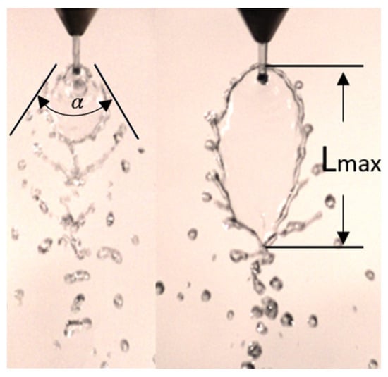
Figure 3.
Measuring visual dimensions using Image J software (version 1.53).
2.2. Experiment Procedure
The experiments used water as the working fluid. The main parameter monitored was the flow rate of water, which was then used to calculate the jet velocity of the nozzle. The Weber number and Reynolds number were calculated based on the jet diameter and jet velocity () to study the characteristics of the liquid sheet, as shown in Equations (1) and (2). Table 3 presents the different parameters and their operating ranges. The experiments were conducted at a room temperature of 27 °C with a relative humidity of 40–50%.

Table 3.
Experimental parameter.
Before conducting the experiments, the camera and LED light were adjusted to ensure sufficient exposure for capturing images. Once the desired flow rates were set, images of jet collisions and liquid sheet formation could be obtained. This process was repeated to observe variations in the liquid sheets under different impingement configurations. Raw images taken with a high-speed camera were post-processed to measure the length of the liquid sheet and spray angle. LED lights were used during imaging to provide illumination, although their effectiveness may have been affected by the uneven surface of the liquid sheet. ImageJ version 1.53 software was utilized to determine the maximum length of the liquid sheet and spray angle. MATLAB was employed to analyze 1000 images in order to calculate droplet diameter, resulting in an average Sauter mean diameter measurement. All measurements adhered to standardized experiment procedure.
3. Theoretical Methods
3.1. Liquid Sheet Thickness Model
Ranz [41] discussed the liquid sheet formed using pure water at different impingement angles, which considered the collision of double jets. Through the conservation of energy and momentum equations, the following equation was proposed as shown in Equation (3):
where h is the liquid sheets thickness and is the diameter of the injector orifice. When the impingement angle θ was less than 60° and the azimuthal angle of the liquid sheets was 180°, the sheets thickness was negative, indicating that the liquid sheets may have shifted towards the impingement direction, and they all appeared on one side of the impingement point. Miller [42] discovered that when there was a non-zero angle between doublet-impinging jets, not only did the impinged liquid sheets spread in the direction of the jet flow, but they also expanded in the opposite direction to that flow. The calculation method assumed equal flow velocity for liquid droplets within these liquid sheets as compared to jet velocity. The impinged liquid sheets then flowed radially outward from their center of impact, with derivation based on the conservation of momentum, continuity equation, and symmetry considerations for these sheets. Gravity, viscosity, and surface tension effects were ignored in this derivation process resulting in Equation (4):
Hasson and Peck [10] assumed constant static pressure in the flow field, resulting in straight streamlines. When the doublet jets collided, a stagnation point was created. By applying the principles of energy and mass conservation in the flow field, we can establish a relationship between the thickness of the liquid sheets and the azimuthal angle. The liquid flow expanded within an elliptical plane, with a long axis of 2R/sinθ and a short axis of 2R:
The result was consistent with the experimental results of Taylor [8] (θ = 60°, 45°, and 30°), and the equation was roughly consistent with Equation (4) derived by Miller [38] for large θ ( and ). However, when the impinging angle (θ) was less than 60°, the thickness ratio of the liquid sheets at both end vertices of the long axis remained constant. This ratio can be calculated using
Ibrahim and Przekwas [11] proposed that the liquid sheet should be free and unbounded, rather than fixed in an ellipse. They also suggested that at lower Weber numbers (500 < We < 2000), the breakup of the liquid sheet was influenced by a stationary antisymmetric wave. When the Weber number was greater than 2000, liquid sheet breakup was controlled by the Kelvin–Helmholtz wave growth. The relationship for the initial liquid sheets thickness was derived based on the study of Naber and Reitz [43] as shown in Equation (7). Under low Weber number conditions, the liquid sheet thickness can be described using Equation (8):
Equation (7) demonstrates that β is the attenuation factor, derived from the conservation of mass and momentum equations. It signifies the rate at which the liquid sheet thickness diminishes. A smaller β value suggests a slower decrease in liquid sheet thickness, while a larger value indicates a faster decline. The relationship between β and the impingement angle can be expressed as follows:
3.2. Liquid Sheet Maximum Length Model
Li and Ashgriz [19] proposed a theoretical model to predict the maximum liquid sheet thickness using the impingement angle and azimuth angle:
In the closed rim mode, the length of the liquid sheet fragmentation and the impingement angle increased as the Weber number increased. However, at high Weber numbers, it was not possible to maintain the closed rim mode, and a linear relationship cannot be observed. When the Weber number reached 100, the experimental value was significantly lower than the theoretical model. This happened because, as the Weber number exceeded 100, the liquid sheets transitioned into the open-rim mode and experienced a decrease in fragmentation length with increasing Weber numbers. Hence, this equation can be utilized to examine the maximum lengths of liquid sheets for doublet jets and quadruple jets at low Weber numbers.
4. Results and Discussion
4.1. Observation of Liquid Sheets and Analysis of Atomization Mechanism
4.1.1. Doublet Jets’ Atomization
The images in Figure 4 depict the atomization process of doublet jets with a nozzle diameter of 0.8 mm. These images show how the morphology of liquid sheets varies at different impingement angles and flow rates. At an impingement angle of 90° and a flow rate ranging from 0.03 to 0.05 LPM (flow velocity 1 to 1.66 m/s), we observe the formation of a single closed liquid sheet edge with protrusions after impingement. The resulting liquid ligament then breaks up into droplets, resembling the closed rim mode.
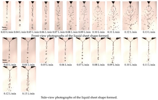
Figure 4.
The liquid sheet for the 0.8 mm nozzle diameter at different flow rates in the doublet-impinging jets.
When the flow rate increases to 0.06–0.09 LPM (flow velocity of 1.99–2.99 m/s), a rippled wave pattern called the periodic drop mode appears on the surface of the liquid sheets. For a flow rate of 0.10–0.11 LPM (flow velocity of 3.32–3.65 m/s), the liquid sheets become more distinct, and there is a significant increase in scattered droplets around them, accompanied by an increase in length and width along with wrinkled ripples breaking into irregularly shaped droplets falling. At this point, downstream of the liquid sheets also starts to break into irregular liquid ligaments, gradually transitioning to the open rim mode. At a flow rate of 0.12–0.13 LPM (flow velocity of 3.98–4.31 m/s), due to rapid impact from the liquid jets, the liquid sheets quickly disintegrate into liquid ligaments which then fracture into irregularly sized droplets known as the fully development mode.
4.1.2. Doublet Jets’ Atomization
Figure 5 displays images of atomization with a jet diameter of 1.1 mm. These images illustrate the formation of a liquid sheet at various impingement angles and velocities. When the impingement angle is 90°, flow velocities ranging from 0.53 to 1.23 m/s (flow rates of 0.03 to 0.07 LPM) consistently show the closed rim mode. At a velocity of 1.4 m/s, a ripple-like waveform appears on the surface of the liquid sheet, referred to as the periodic drop mode. Velocities between 1.40 and 2.28 m/s (flow rates of 0.08 to 0.13 LPM) only result in an increase in width and length for the liquid sheet.

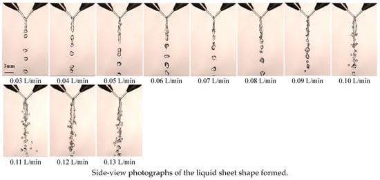
Figure 5.
The liquid sheet for the 1.1 mm nozzle diameter at different flow rates in the doublet-impinging jets.
4.1.3. Quadruplet Jets’ Atomization
Four nozzles are arranged in a circular pattern to create four jets of liquid. The impact point of these jets was observed in order to visualize the fragmentation of the liquid sheets, as shown in Figure 6. At flow rates ranging from 0.03 to 0.06 LPM (flow velocities between 1.00 and 1.99 m/s), a single closed edge is formed after the impact, with structures appearing on this edge. The resulting liquid ligament then breaks into droplets, similar to the doublet-jet collision’s closed rim mode. When the flow rate increases to 0.07–0.08 LPM (flow velocities between 2.32 and 2.65 m/s), periodic ripples appear on the surface of the falling liquid sheet, creating a periodic drop mode. At even higher flow rates (2.99–3.32 m/s or flow rates of 0.09-0/10 PM), an open liquid edge mode is formed. For flow rates above this range (0/11-013 LPM), a fully developed mode is achieved. The behavior of the liquid sheets impacted by quadruplet jets and doublet jets is very similar; however, as jet momentum increases, there is no formation of liquid threads or fragmentation into droplets.
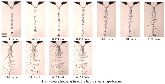

Figure 6.
The liquid sheet for the 0.8 mm nozzle diameter at different flow rates in the quadruplet-impinging jets.
4.1.4. Quadruplet Jets’ Atomization
The images in Figure 7 depict the atomization of quadruplet jets with a larger jet diameter. For flow rates ranging from 0.03 to 0.1 LPM, the impingement results in the formation of a single closed meniscus with protruding structures on the liquid edge. The liquid ligament breaks up into droplets, like the collision of doublet jets known as the closed rim mode. As the flow rate increases (from 0.11 to 0.13 LPM), ripple-like waves appear on the surface of the liquid sheets, forming periodic drops. The pattern caused by quadruplet-jet impingement closely resembles that observed in doublet-jet impingement, with only two modes: closed rims and periodic drop. There are no significant differences in how these liquid sheets fragment between quadruplet-jet impingement and doublet-jet impingement. However, quadruplet-jet atomization is less affected by changes in pipe diameter and flow rate compared to doublet jets, resulting in less sensitivity regarding changes in the liquid sheet impingement mode.
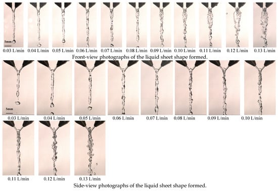
Figure 7.
The liquid sheet for the 1.1 mm nozzle diameter at different flow rates in the quadruplet-impinging jets.
4.2. Liquid Sheet Thickness
Figure 8 shows how the liquid film thickness constants is affected by the jet diameter. The jet velocities for the 0.8 mm and 1.1 mm jets are 2.32 m/s and 1.23 m/s, respectively, resulting in Weber numbers of 60 and 23 for each diameter. The flow velocity was chosen to produce noticeable and distinguishable liquid sheet patterns, regardless of whether it was a doublet or quadruplet jet. By measuring the distance from the edge of the liquid sheet at different azimuthal angles, we can estimate its thickness using theoretical models from the literature. The results indicate a consistent trend in predicted liquid sheet thickness when comparing jets with the same diameter and considering azimuthal angle. However, it is worth noting that Ranz’s theoretical model Ranz [41] was not applicable for large azimuthal angles, as it yielded negative values for liquid sheet thicknesses.
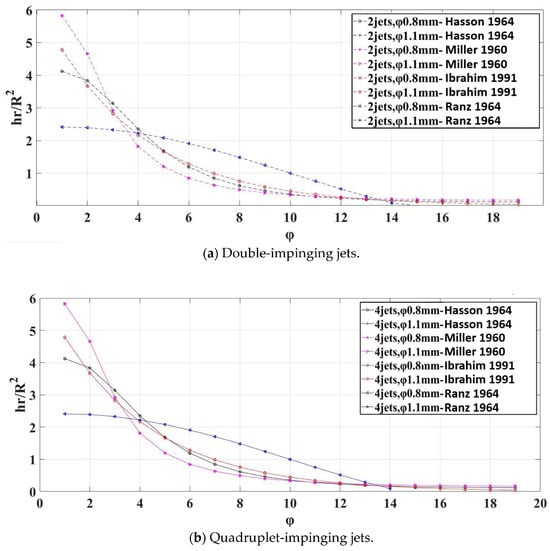
Figure 8.
The relationship between the liquid sheet thickness constants and the azimuthal angle for different nozzle diameters (flow rate of 70 mL/min, θ = 90°) in experimental results [10,11,41,42].
Figure 9 compares the liquid sheet thickness at different azimuthal angles. The results indicate that for a nozzle diameter of 0.8 mm, both doublet and quadruplet impinging result in a liquid sheet thickness ranging from approximately 0.02 mm to 0.05 mm. On the other hand, for a nozzle diameter of 1.1 mm, regardless of whether it is doublet or quadruplet impinging, the liquid sheet thickness exceeds 0.05 mm at smaller azimuth angles and approaches 0.05 mm when the azimuth angle exceeds 100 degrees.
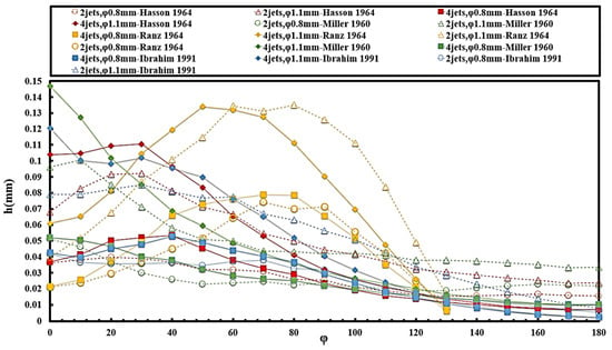
Figure 9.
The relationship between liquid sheet thickness and azimuthal angle for different nozzle diameters (flow rate of 70 mL/min, θ = 90°) in experimental results [10,11,41,42].
4.3. Liquid Sheet Length
From the experimental results, it is observed that as velocity increases, the liquid sheets transition through different modes: closed rim mode, periodic shedding mode, open edge mode, and fully developed mode. Figure 10 plots the experimental results alongside the literature correlation [19]. The two dashed lines represent doublet-impingement angles at 90 degrees, measured under the closed-rim mode. The analysis shows a linear relationship between liquid film length and the Weber number of the jet. Unlike previous studies that focused on high Weber numbers (We > 150) and observed significant deviations from analytical predictions at different impingement angles, this experiment reveals a similar linear relationship between quadruplet impingement and doublet impingement at low Weber numbers (We < 100).
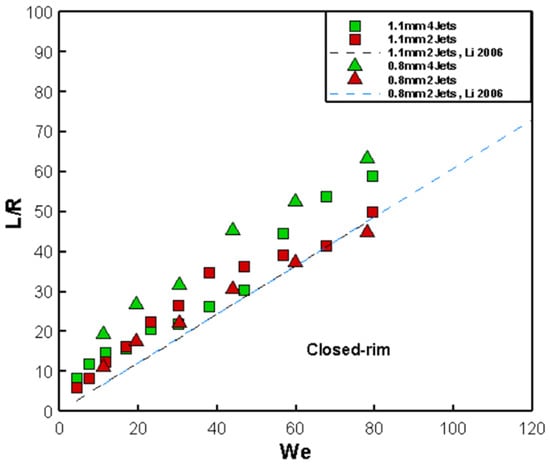
Figure 10.
The correlation between the liquid sheet length and experimental data [19] for the 0.8 mm and 1.1 mm nozzle diameter.
4.4. Spray Angle from Doublet and Quadruplet Jets
The spray angle in this study, denoted by α, refers to the cone angle observed from the front view. Its definition is illustrated in Figure 3, where the cone angle is determined by taking two clear boundaries from the spray field image. This spray angle reflects the mixing effect of multiple jets and effectively represents the divergence of the atomization space. The quantitative analysis results, as shown in Figure 11, indicate that with an increase in Weber number, the spray angle gradually increases. This is because the jet velocity increases, leading to an increase in the component of jet momentum along the X-axis (lateral momentum). This intensifies the mixing of the doublet jets, causing a more pronounced lateral development of the spray field, hence the gradual increase in the spray angle. When the jet velocity is sufficient, the spray angle stabilizes, reaching a maximum of 85°, which is less than the impingement angle of 90°. For the 0.8 mm orifice, regardless of whether it is quadruplet or doublet impinging, the trend remains the same. In the case of the 1.1 mm orifice, the spray angle is significantly influenced by surface tension, with the doublet-impinging spray angle being greater than the quadruplet-impinging spray angle.
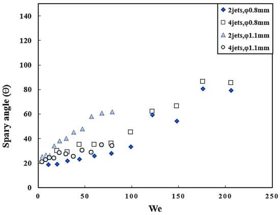
Figure 11.
The spray angle of impinging-jet atomization.
4.5. Liquid Droplet Size from Doublet and Quadruplet Jets
The study investigates the droplet size generated by a jet nozzle with a diameter of 0.8 mm at a Reynolds number of 3000, resulting in droplet sizes of approximately 400 μm, as shown in Figure 12. For the doublet-impinging jets with a nozzle diameter of 1.1 mm, influenced by the expansion of the liquid sheet interval, the droplet size shows a slight increase at low flow rates. However, as the flow rate increases, the droplet size decreases to around 600 μm. The droplet size is larger than that of the 0.8 mm orifice, aligning with the trend observed by Lai, Huang, and Jiang [16], where increasing flow rates lead to smaller droplet sizes.
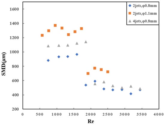
Figure 12.
Liquid droplet size of impinging-jet atomization.
4.6. Comparison of Liquid Sheet Contour and Area
The contour lines of the liquid sheet are generated from images of the liquid sheet taken at various jet diameters and flow rates (Figure 13). The changes in the liquid sheet pattern can be observed using polar coordinates. Only Weber numbers less than 100 are plotted for the 0.8 mm jet diameter because beyond this value, it transitions to an open-edge mode where the contour lines become unclear. When comparing the four-jet configuration to the two-jet configuration, we can observe that the liquid sheet width is narrower in the former. The changes in the liquid sheet become more pronounced with increasing Weber numbers. It is found that the liquid column rapidly expands radially and forms an elliptical-shaped liquid sheet, which differs from the leaf-shaped liquid sheet formed using doublet-impinging jets. Clear variations in the liquid sheet can be observed for a 1.1 mm jet diameter, ranging from 30 mL/min to 130 mL/min. These variations follow similar trends for different jet diameters. Panão and Delgado [23] predicted similar atomization effects for low-speed doublet-impinging and triplet-impinging jets, but they emphasized the significant influence of geometric shapes on the dynamics of triplet-impinging jets. In our experiment using a four-jet stereoscopic configuration, we observed clear similarities to doublet-impinging configurations in planar setups.
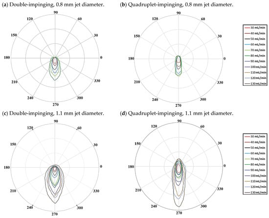
Figure 13.
Comparing liquid sheets at different nozzle diameters and flow rates.
5. Final Remarks and Conclusions
5.1. Summary
This study analyzes the characteristics of atomization produced using doublet and quadruplet jets in planar and stereoscopic configurations. The research examines different parameters such as impingement angle, nozzle diameter, and flow velocity. Measurement results obtained from image analysis are compared with a theoretical model to investigate the thickness and length of the liquid sheets.
5.2. Conclusions
- The investigation of atomization parameters in planar and stereoscopic impinging configurations showed that the length of the impact fragmentation increases with higher Weber numbers. The atomization process can be categorized into four modes: closed rim mode, periodic dropping mode, open liquid edge mode, and complete fragmentation mode.
- Low-speed impinging atomization was considered in this study, and it was observed that both doublet-impinging and quadruplet-impinging atomization exhibited similar flow patterns. At low flow rates (We < 100), the liquid sheet area continues to expand without breaking easily. The closed rim mode can be observed regardless of the jet diameter. At high flow rates (We > 100), it transitioned into an open liquid edge mode.
- Based on the experimental data, it was clear that changes in the structure of the impacting liquid and an increase in the number of jets did not cause significant modifications to the pattern of liquid sheets as the Weber number increased. The length and width of the liquid sheets also followed a similar trend as predicted by the theoretical models.
- According to Panão and Delgado [23], the atomization of doublet impinging and triplet impinging at low flow rates has similar effects. However, the geometric shape of the atomizer greatly affects triplet impinging. In our experiment, even though we used quadruplet jets in a stereoscopic manner, the resulting liquid patterns still resemble those produced with doublet-impinging jets. This study provides valuable information for the design of future stereoscopic impinging atomizers.
- The multiple-impinging-jet spray system can be used in various industries such as combustion, electronics, agriculture, and others. As industrial technology advances, the design of the system is evolving towards lighter solutions and more compact atomization systems. This study contributes to this downsizing trend by offering nozzle configurations that provide greater operational flexibility in limited space. Moreover, it enables more precise control over spraying, enhancing product quality during manufacturing.
Author Contributions
Conceptualization, J.-Y.W.; software, J.-Y.W.; investigation, J.-Y.W.; writing—original draft preparation, J.-Y.W. and Y.-H.L.; writing—review and editing, J.-Y.W. and Y.-H.L.; supervision, Y.-H.L.; funding acquisition, Y.-H.L. All authors have read and agreed to the published version of the manuscript.
Funding
This research was funded by the Ministry of Science and Technology in Taiwan under the grant number MOST 109-2221-E-009-021-MY3.
Data Availability Statement
All data are presented in this article in the form of figures and tables.
Conflicts of Interest
The authors declare no conflicts of interest.
Nomenclature
| orifice area of injector (mm2) | |
| Sauter mean diameter (μm) | |
| jet diameter (mm) | |
| ligament diameter (mm) | |
| L | length of injector tube (mm) |
| impingement distance (mm) | |
| liquid sheet maximum length (mm) | |
| h | thickness of sheet (mm) |
| thickness of sheet at radial position (mm) | |
| thickness of sheet at initial position (mm) | |
| number of injectors | |
| Q | volumetric working fluid injection rate (ml/min) |
| R | orifice radius of injector (mm) |
| Re | Reynolds number |
| re | radial distance from the impingement point (mm) |
| r | radial position of sheet (mm) |
| jet mean velocity (m/s) | |
| We | Weber number |
| W | liquid sheet width (mm) |
| X | horizontal coordinate from impingement point |
| Y | horizontal coordinate from impingement point |
| Z | vertical coordinate from impingement point |
| spray angle | |
| β | parameters |
| θ | half of jet impingement angle, deg |
| viscosity coefficient (mPa·s) | |
| density of pure water (kg/m3) | |
| ρ | density of working fluid (kg/m3) |
| σ | surface tension of working fluid (mN/m) |
| υ | kinematic viscosity (Pa·s) |
| azimuthal angle of sheet (deg) | |
| ψ | angle between the tangent to the rim of the cardioid and the radius vector |
| l | liquid |
| j | jet |
References
- Arora, E.K.; Sharma, V.; Ravi, A.; Shahi, A.; Jagtap, S.; Adhikari, A.; Dash, J.K.; Kumar, P.; Patel, R. Conducting Polymer Based Ink for Inkjet Printing: Formulation, Fabrication and Application. Preprint 2023. [CrossRef]
- Ji, M.; Wu, Z.; Ferrari, A.; Fu, L.; Vento, O. Experimental Investigation on Gasoline—Water Mixture Fuel Impingement Preparation Method and Spray Characteristics with High Injection Temperatures and Pressures. Energies 2023, 16, 6026. [Google Scholar] [CrossRef]
- Nienke, T.; Gomez Bonilla, J.S.; Kwade, A.; Eggerath, D. Combination of different nozzle concepts for simultaneous optimization of heat transfer and its uniform distribution in convection drying applications. Dry. Technol. 2024, 42, 48–60. [Google Scholar] [CrossRef]
- Pan, Q.; Lu, Y.; Hu, H.; Hu, Y. Review and research prospects on sprinkler irrigation frost protection for horticultural crops. Sci. Hortic. 2024, 326, 112775. [Google Scholar] [CrossRef]
- Yang, L.-J.; Qu, Y.-Y.; Fu, Q.-F.; Gu, B.; Wang, F. Linear Stability Analysis of a Non-Newtonian Liquid Sheet. J. Propuls. Power 2010, 26, 1212–1225. [Google Scholar] [CrossRef]
- Rupe, J.H. The Liquid-Phase Mixing of a Pair of Impinging Streams; California Institute of Technology: Pasadena, CA, USA, 1953. [Google Scholar]
- Heidmann, M.F.; Priem, R.J.; Humphrey, J.C. A Study of Sprays Formed by Two Impinging Jets; National Advisory Committee for Aeronautics: Washington, DC, USA, 1957. [Google Scholar]
- Taylor, G. Formation of thin flat sheets of water. Proc. R. Soc. Lond. Ser. A Math. Phys. Sci. 1961, 259, 1–17. [Google Scholar]
- Dombrowski, N.D.; Hooper, P. A study of the sprays formed by impinging jets in laminar and turbulent flow. J. Fluid Mech. 1964, 18, 392–400. [Google Scholar] [CrossRef]
- Hasson, D.; Peck, R.E. Thickness distribution in a sheet formed by impinging jets. AIChE J. 1964, 10, 752–754. [Google Scholar] [CrossRef]
- Ibrahim, E.A.; Przekwas, A.J. Impinging jets atomization. Phys. Fluids A Fluid Dyn. 1991, 3, 2981–2987. [Google Scholar] [CrossRef]
- Anderson, W.; Ryan, H.; Pal, S.; Santoro, R. Fundamental studies of impinging liquid jets. In Proceedings of the 30th Aerospace Sciences Meeting and Exhibit, Reno, NV, USA, 6–9 January 1992; p. 458. [Google Scholar]
- Ryan, H.M.; Anderson, W.E.; Pal, S.; Santoro, R.J. Atomization characteristics of impinging liquid jets. J. Propuls. Power 1995, 11, 135–145. [Google Scholar] [CrossRef]
- Chojnacki, K.; Feikema, D. Atomization studies of gelled liquids. In Proceedings of the 30th Joint Propulsion Conference and Exhibit, Indianapolis, IN, USA, 27–29 June 1994; p. 2773. [Google Scholar]
- Kang, B.; Shen, Y.; Poulikakos, D. Holography experiments in the breakup region of a liquid sheet formed by two impinging jets. At. Sprays 1995, 5, 387–402. [Google Scholar] [CrossRef]
- Lai, W.-H.; Huang, W.; Jiang, T.-L. Characteristic study on the like-doublet impinging jets atomization. At. Sprays 1999, 9, 277–289. [Google Scholar] [CrossRef]
- Lai, W.-H.; Huang, T.-H.; Jiang, T.-L.; Huang, W. Effects of fluid properties on the characteristics of impinging-jet sprays. At. Sprays 2005, 15, 457–468. [Google Scholar] [CrossRef]
- Inamura, T.; Shirota, M. Effect of velocity profile of impinging jets on sheet characteristics formed by impingement of two round liquid jets. Int. J. Multiph. Flow 2014, 60, 149–160. [Google Scholar] [CrossRef]
- Li, R.; Ashgriz, N. Characteristics of liquid sheets formed by two impinging jets. Phys. Fluids 2006, 18, 087104. [Google Scholar] [CrossRef]
- Soni, A.; Sanjay, V.; Das, A.K. Formation of fluid structures due to jet-jet and jet-sheet interactions. Chem. Eng. Sci. 2018, 191, 67–77. [Google Scholar] [CrossRef]
- Panão, M.R.O.; Delgado, J. Characteristics of multijet impingement sprays for water applications. In Proceedings of the ILASS-Americas 25th Annual Conference on Liquid Atomization and Spray Systems, Pittsburgh, PA, USA, 16 May 2013; pp. 1–10. [Google Scholar]
- Avulapati, M.M.; Rayavarapu Venkata, R. Experimental studies on air-assisted impinging jet atomization. Int. J. Multiph. Flow 2013, 57, 88–101. [Google Scholar] [CrossRef]
- Panão, M.R.O.; Delgado, J.M.D. Toward the design of low flow-rate multijet impingement spray atomizers. Exp. Therm. Fluid Sci. 2014, 58, 170–179. [Google Scholar] [CrossRef]
- Baek, S.; Han, J. Simulation of thin liquid jets with threads. Comput. Animat. Virtual Worlds 2017, 28, e1768. [Google Scholar] [CrossRef]
- Kebriaee, A.; Kazemi, S. Experimental Study of Primary Atomization in Triple Co-Planar and Non-Planar Impinging Jets. At. Sprays 2019, 29, 1027–1041. [Google Scholar] [CrossRef]
- Bremond, N.; Villermaux, E. Atomization by jet impact. J. Fluid Mech. 2006, 549, 273–306. [Google Scholar] [CrossRef]
- Lee, J.G.; Fakhri, S.; Yetter, R. Atomization and spray characteristics of gelled-propellant simulants formed by two impinging jets. In Proceedings of the 45th AIAA/ASME/SAE/ASEE Joint Propulsion Conference & Exhibit, Denver, CO, USA, 2–5 August 2009; p. 5241. [Google Scholar]
- Baek, G.; Kim, S.; Han, J.; Kim, C. Atomization characteristics of impinging jets of gel material containing nanoparticles. J. Non-Newton. Fluid Mech. 2011, 166, 1272–1285. [Google Scholar] [CrossRef]
- Panão, M.R.O.; Delgado, J. Effect of pre-impingement length and misalignment in the hydrodynamics of multijet impingement atomization. Phys. Fluids 2013, 25, 012105. [Google Scholar] [CrossRef]
- Bai, F.; Diao, H.; Zhang, M.; Chang, Q.; Wang, E.; Du, Q. Breakup characteristics of power-law liquid sheets formed by two impinging jets. Fluid Dyn. Res. 2014, 46, 055506. [Google Scholar] [CrossRef]
- Ma, Y.-C.; Bai, F.-Q.; Chang, Q.; Yi, J.-M.; Jiao, K.; Du, Q. An experimental study on the atomization characteristics of impinging jets of power law fluid. J. Non-Newton. Fluid Mech. 2015, 217, 49–57. [Google Scholar] [CrossRef]
- Zhao, F.; Yang, L.-J.; Mo, C.-J.; Qin, L.-Z. Spray Characteristics of Unlike Impinging Jets. J. Propuls. Power 2017, 33, 1260–1271. [Google Scholar] [CrossRef]
- Deng, H.-Y.; Zhuo, C.-F.; Feng, F. A simplified linear model and breakup characteristics of power-law sheet formed by a doublet impinging injector. Proc. Inst. Mech. Eng. Part G J. Aerosp. Eng. 2018, 232, 1035–1046. [Google Scholar] [CrossRef]
- Kashanj, S.; Kebriaee, A. The effects of different jet velocities and axial misalignment on the liquid sheet of two colliding jets. Chem. Eng. Sci. 2019, 206, 235–248. [Google Scholar] [CrossRef]
- Indiana, C.; Boust, B.; Bellenoue, M.; Azuma, N. Effect of Injector Design on the Combustion of Ethanol and Hydrogen-Peroxide Sprays. J. Propuls. Power 2019, 35, 652–661. [Google Scholar] [CrossRef]
- Deng, H.-Y.; Qu, Z.; Liao, W.; Yang, H. A parametric study on impinging atomization of gelled fluid using nano-SiO2 gellant. J. Appl. Sci. Eng. 2021, 24, 573–585. [Google Scholar]
- Panão, M.R.O.; Moreira, A.L.N.; Durão, D.G. Transient analysis of intermittent multijet sprays. Exp. Fluids 2011, 53, 105–119. [Google Scholar] [CrossRef]
- Xia, Y. Atomization Characteristics of Impinging Liquid-Gas Jets. Master’s Thesis, The Petroleum Institute, Abu Dhabi, United Arab Emirates, 2016. [Google Scholar]
- Pizziol, B.; Costa, M.; Panão, M.O.; Silva, A. Multiple impinging jet air-assisted atomization. Exp. Therm. Fluid Sci. 2018, 96, 303–310. [Google Scholar] [CrossRef]
- Saurabh, A.; Deshmukh, D.; Nath, S.; Agarwal, D.; Vivek, K.; Kabiraj, L. Impingement Atomization of Carbopol Gels. AIAA J. 2022, 60, 6463–6472. [Google Scholar] [CrossRef]
- Ranz, W.E. Some Experiments on the Dynamics of Liquid Films. J. Appl. Phys. 1959, 30, 1950–1955. [Google Scholar] [CrossRef]
- Miller, K.D. Distribution of Spray From Impinging Liquid Jets. J. Appl. Phys. 1960, 31, 1132–1133. [Google Scholar] [CrossRef]
- Naber, J.; Reitz, R.D. Modeling engine spray/wall impingement. SAE Trans. 1988, 22, 118–140. [Google Scholar]
Disclaimer/Publisher’s Note: The statements, opinions and data contained in all publications are solely those of the individual author(s) and contributor(s) and not of MDPI and/or the editor(s). MDPI and/or the editor(s) disclaim responsibility for any injury to people or property resulting from any ideas, methods, instructions or products referred to in the content. |
© 2024 by the authors. Licensee MDPI, Basel, Switzerland. This article is an open access article distributed under the terms and conditions of the Creative Commons Attribution (CC BY) license (https://creativecommons.org/licenses/by/4.0/).