
Applying the Integral Controllability Property in a Multi-Loop Control for Stable Voltage Regulation in an Active Distribution Network


Abstract
1. Introduction
- The condition of integral controllability is satisfied even in the presence of a high number of DERs;
- Only a single parameter to design;
- Only devices for local measurements are required; no need of network infrastructures for collecting information and data among the control loops;
- Reduction of the interaction’s level;
- Simplicity of the controller’s structure easily implementable in real ADNs.
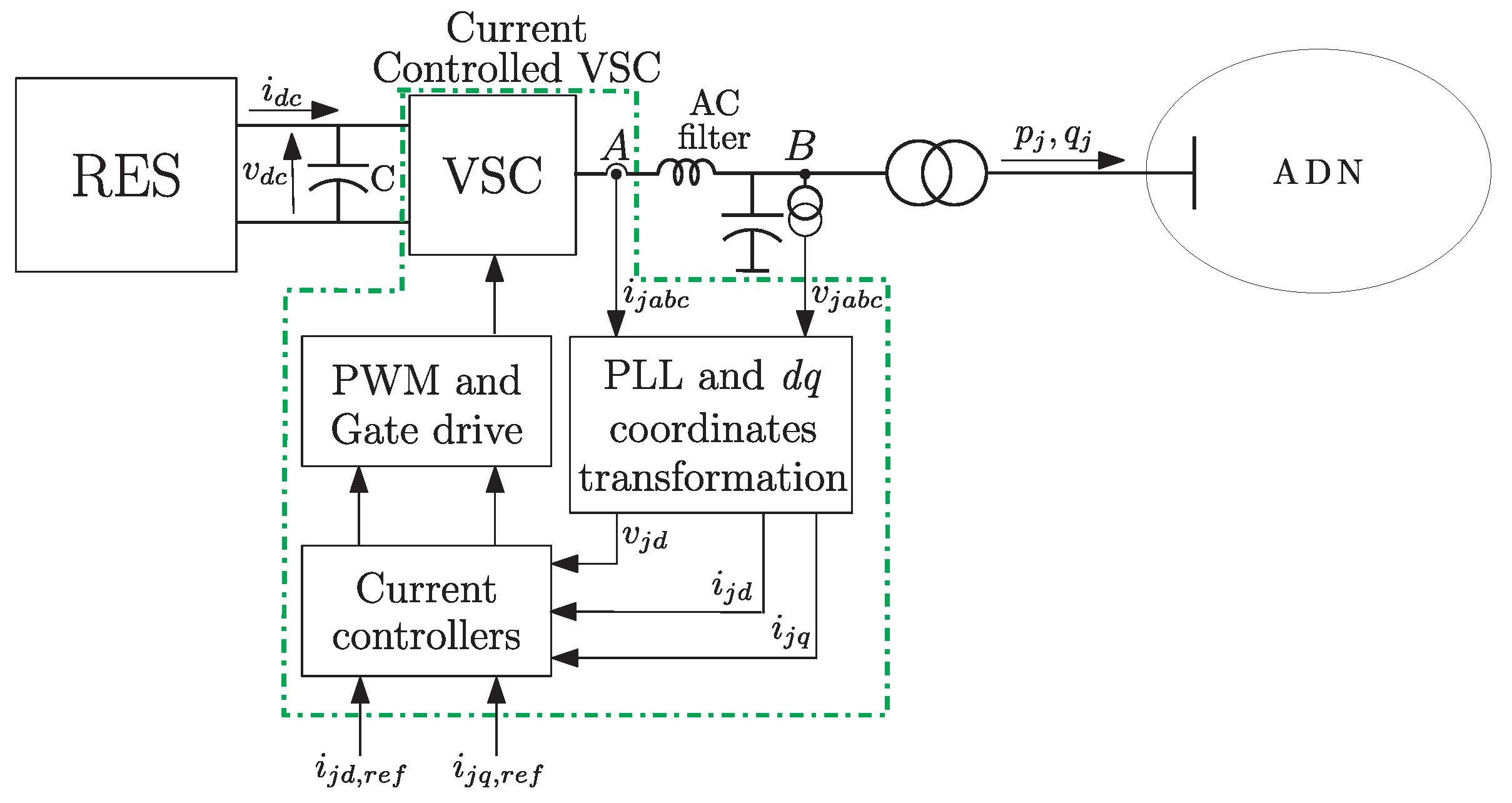
2. DER and DN Models
2.1. DER Model
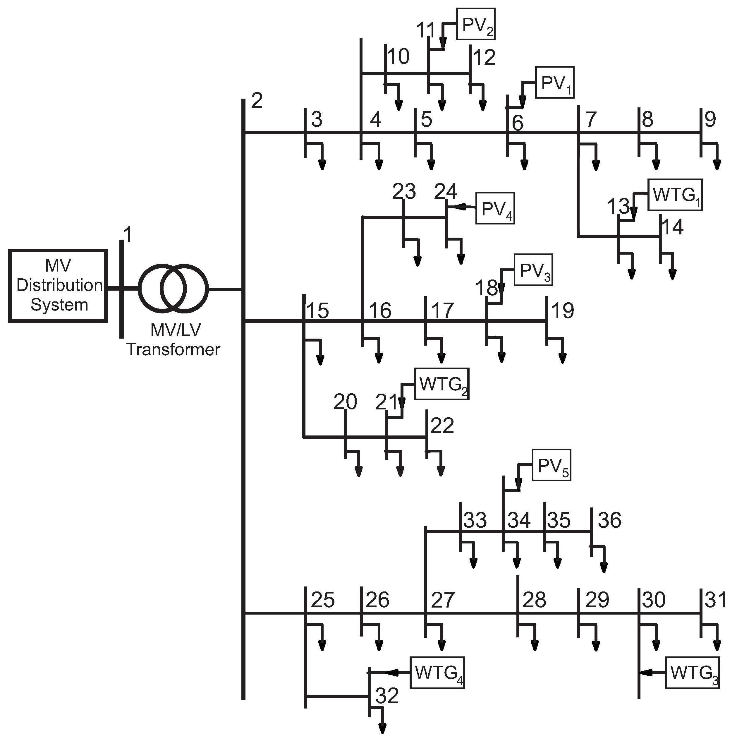
2.2. Distribution Network Model
2.3. Overall MIMO Model
3. Control Design
4. Simulation Studies
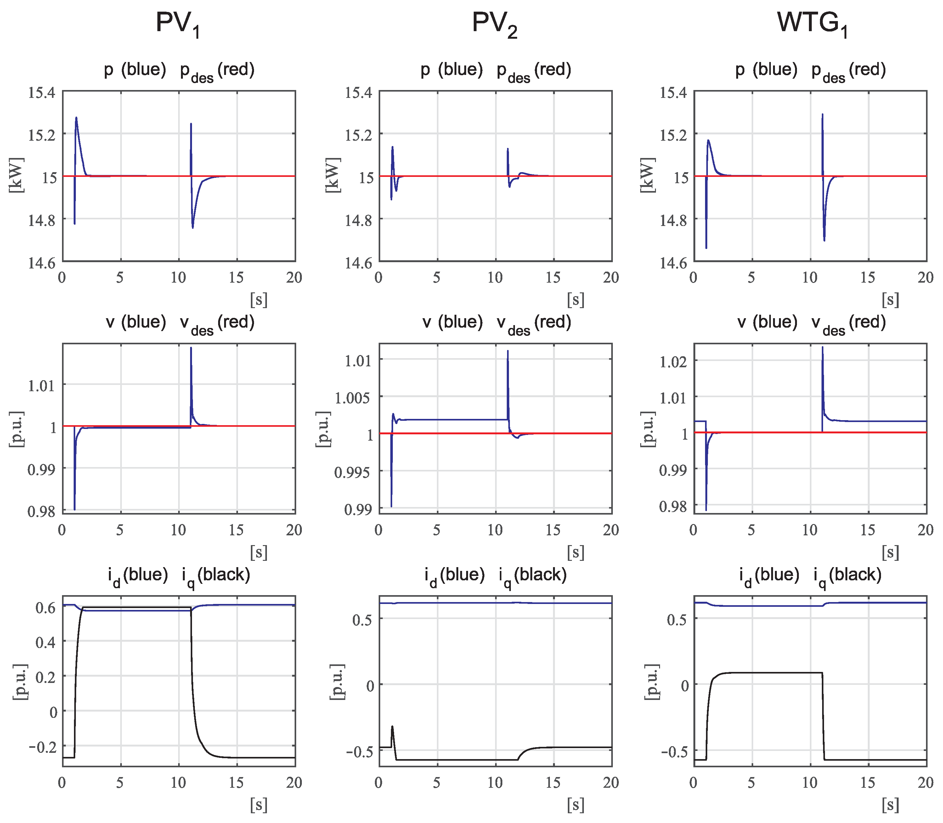
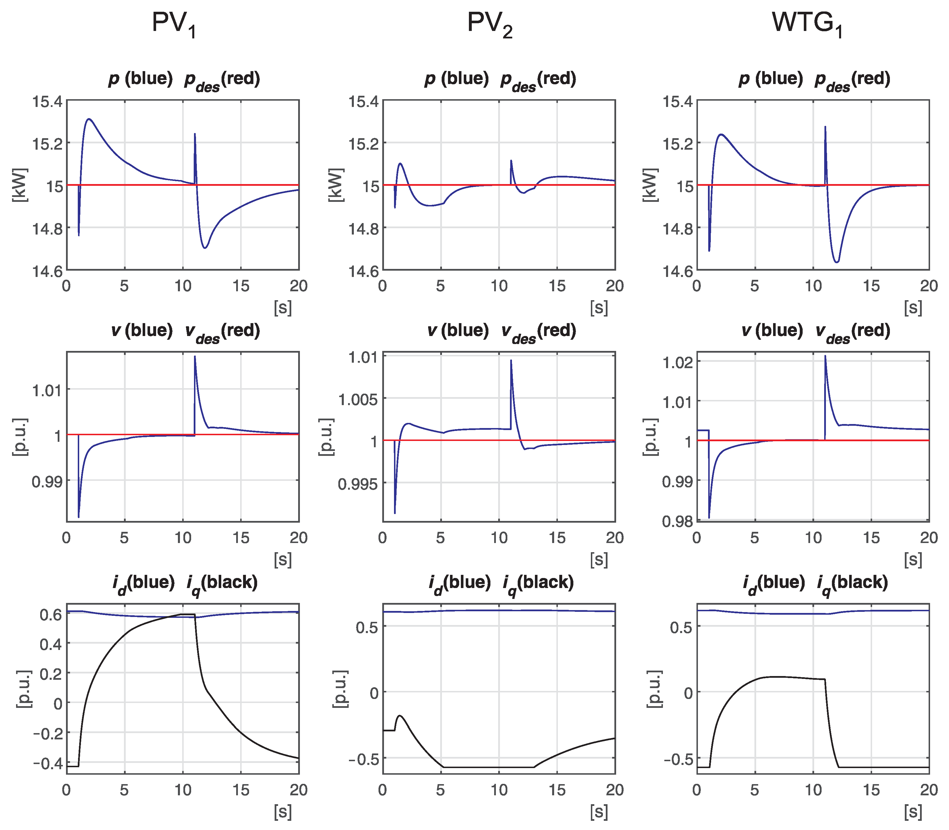
- Case 1:
- Connection and disconnection of a load;
- Case 2:
- Variation in solar radiation;
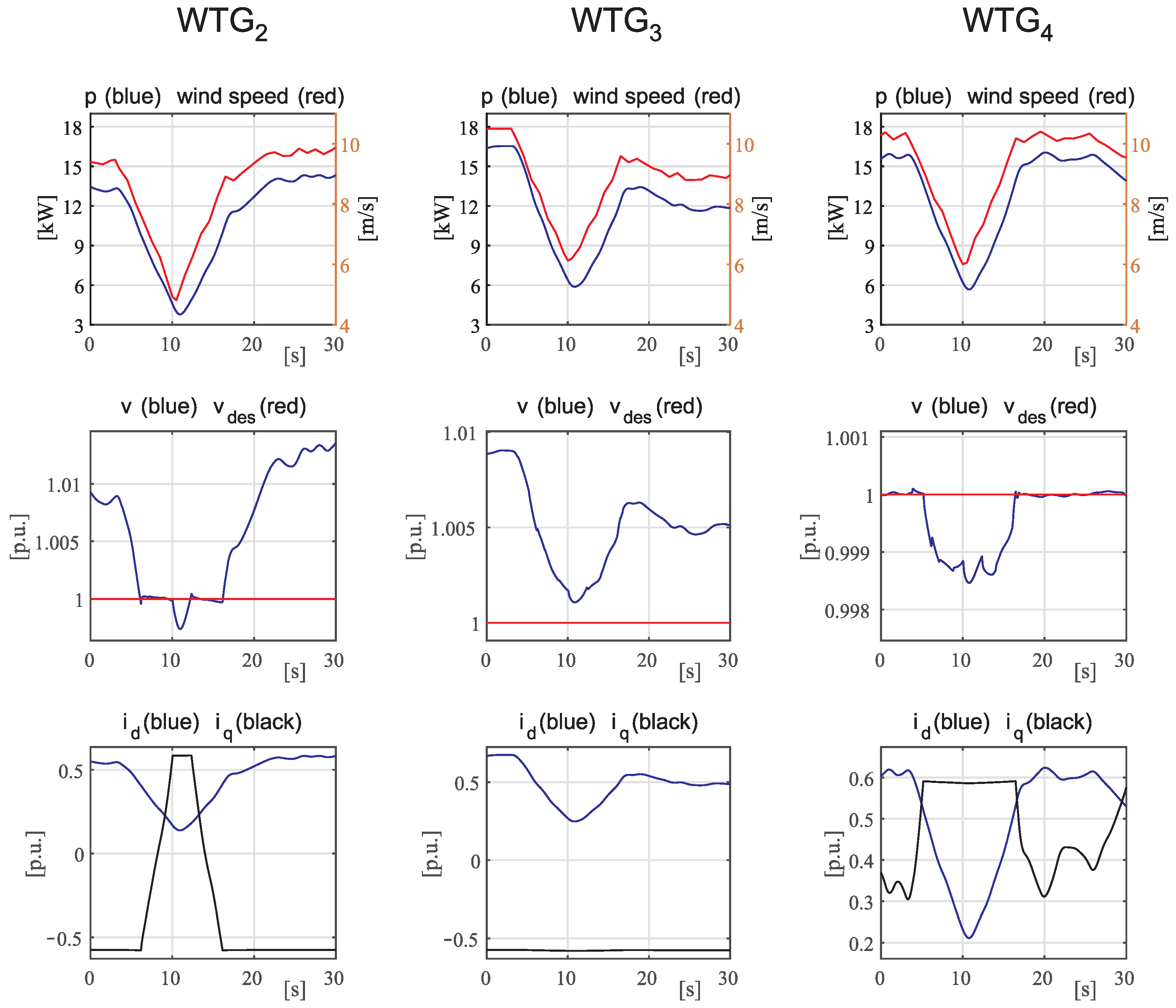
- Case 3:
- Variation in wind speed;
- Case 4:
- Presence of inaccuracy in network line parameters;
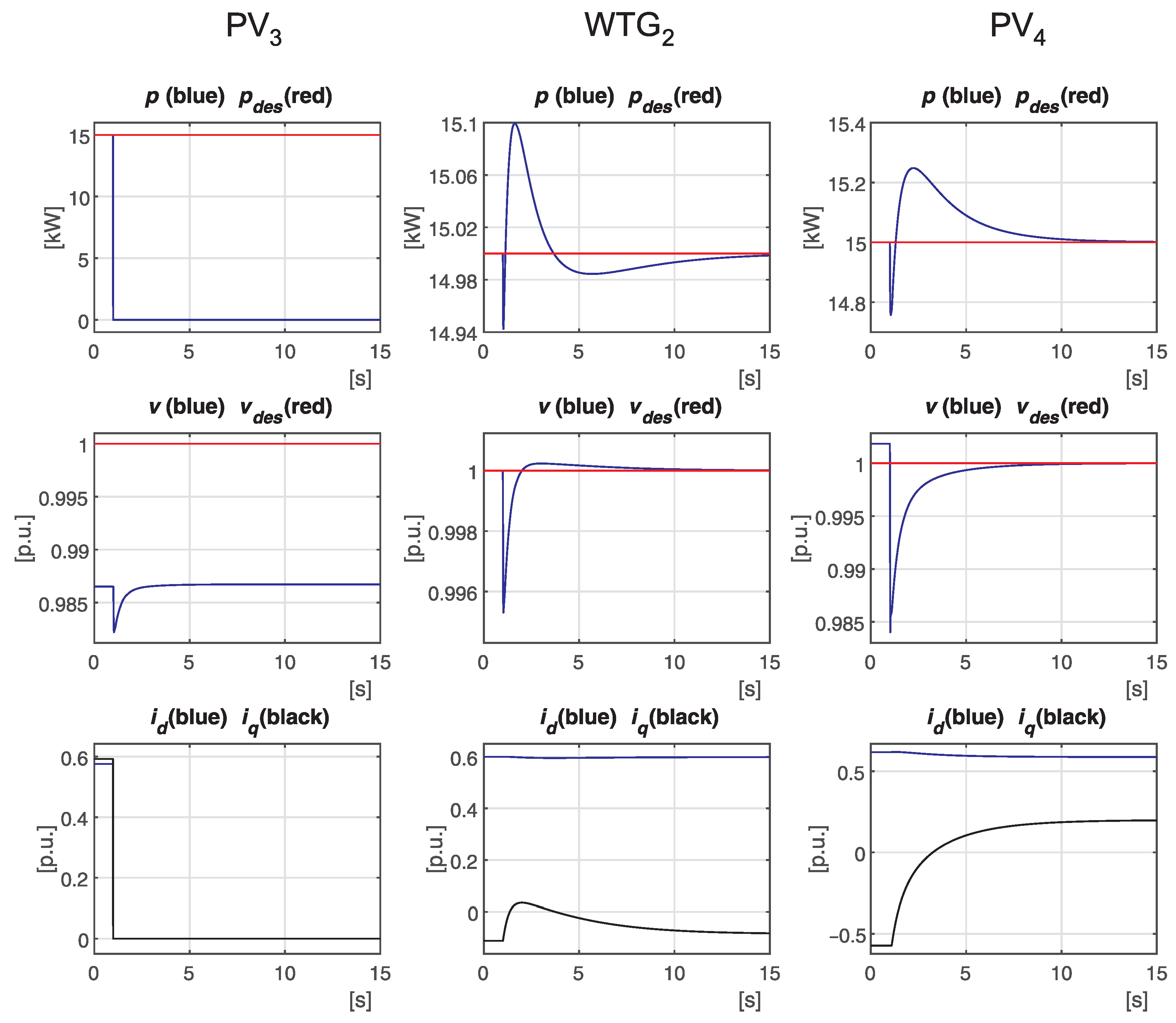
- Case 5:
- Disconnection of a DER.
- Case 6:
- Response to a step variation of of ;
- Case 7:
- As case 1;
- Case 8:
- As case 5.
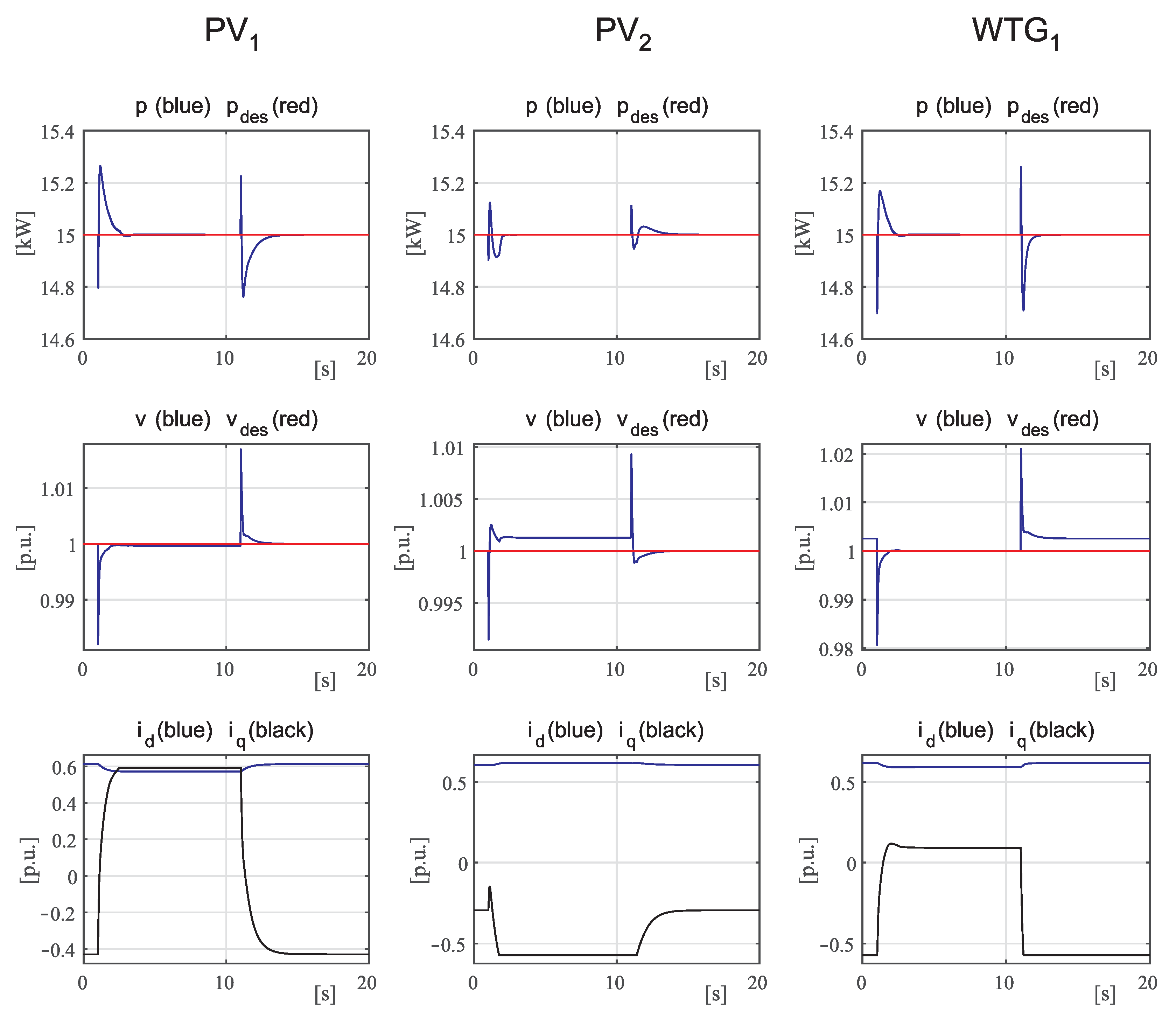
4.1. Case 1
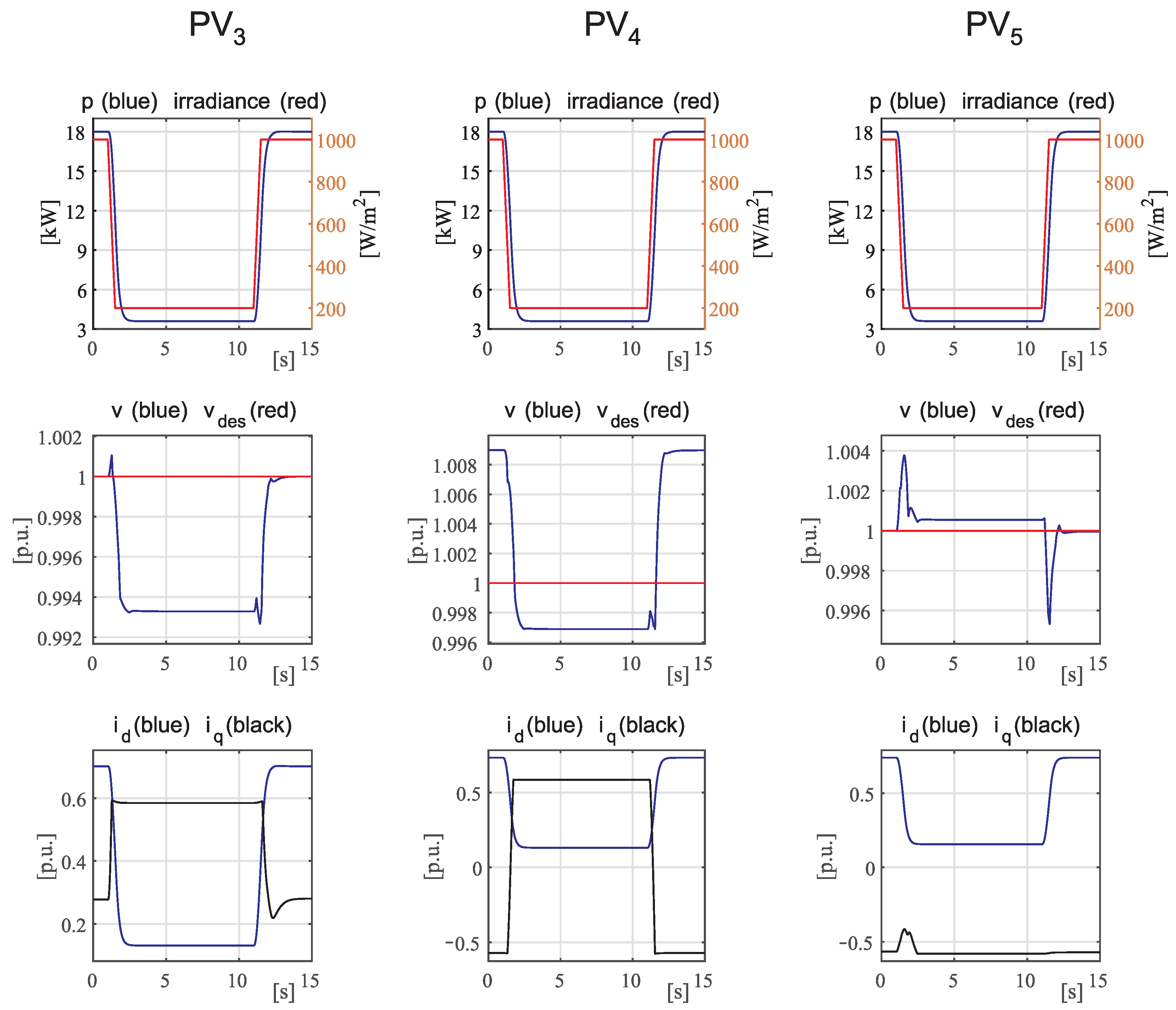
4.2. Case 2
4.3. Case 3
4.4. Case 4
4.5. Case 5
4.6. Comparisons
4.7. Case 6
4.8. Case 7
4.9. Case 8
5. Conclusions
Author Contributions
Funding
Data Availability Statement
Conflicts of Interest
References
- Tatar, S.M.; Aydin, E. Design and operation of renewable energy microgrids under uncertainty towards green deal and minimum carbon emissions. Sustain. Energy Grids Netw. 2024, 37, 101233. [Google Scholar] [CrossRef]
- Abdelkader, A.; Abdelkader, A.; Abdelkader, S.; Benidris, M. Voltage Stability Enhancement Using Local Measurements in Active Distribution Networks. In Proceedings of the 2023 North American Power Symposium (NAPS), Asheville, NC, USA, 15–17 October 2023; pp. 1–6. [Google Scholar]
- Constante, G.; Wang, J. Hierarchical Mechanism of Voltage Instability with Active Distribution Networks. In Proceedings of the 2018 Clemson University Power Systems Conference (PSC), Charleston, SC, USA, 4–7 September 2018; pp. 1–6. [Google Scholar]
- Ferreira, D.M.; Carvalho, P.M. Stability Analysis of Local Control Interactions in Active Distribution Networks. In Proceedings of the 2023 IEEE International Conference on Energy Technologies for Future Grids (ETFG), Wollongong, Australia, 3–6 December 2023; pp. 1–6. [Google Scholar]
- Hatziargyriou, N.; Milanović, J.; Rahmann, C.; Ajjarapu, V.; Cañizares, C.; Erlich, I.; Hill, D.; Hiskens, I.; Kamwa, I.; Pal, B.; et al. Stability definitions and characterization of dynamic behavior in systems with high penetration of power electronic interfaced technologies. In IEEE PES Technical Report PES-TR77; IEEE: Piscataway, NJ, USA, 2020. [Google Scholar]
- Kazeminejad, M.; Banejad, M.; Annakkage, U.; Hosseinzadeh, N. The effect of high penetration level of distributed generation sources on voltage stability analysis in unbalanced distribution systems considering load model. J. Oper. Autom. Power Eng. 2019, 7, 196–205. [Google Scholar]
- Lee, H.; Srivastava, A.K.; Krishnan, V.V.; Niddodi, S.; Bakken, D.E. Decentralized voltage stability monitoring and control with distributed computing coordination. IEEE Syst. J. 2021, 16, 2251–2260. [Google Scholar] [CrossRef]
- Venegas, F.G.; Meunier, S.; Protopapadaki, C.; Perez, Y.; Saelens, D.; Petit, M. Impact of distributed energy resources and electric vehicle smart charging on low voltage grid stability. In Proceedings of the CIRED 2021—The 26th International Conference and Exhibition on Electricity Distribution, Online Conference, 20–23 September 2021. [Google Scholar]
- Rahman, S.; Saha, S.; Islam, S.N.; Arif, M.T.; Mosadeghy, M.; Haque, M.; Oo, A.M. Analysis of power grid voltage stability with high penetration of solar PV systems. IEEE Trans. Ind. Appl. 2021, 57, 2245–2257. [Google Scholar] [CrossRef]
- Ranamuka, D.; Agalgaonkar, A.; Muttaqu, K. Online Voltage Control in Distribution Systems With Multiple Voltage Regulating Devices. IEEE Trans. Sustain. Energy 2014, 5, 617–628. [Google Scholar] [CrossRef]
- Rizvi, S.M.H.; Srivastava, A.K. Integrated T&D voltage stability assessment considering impact of DERs and distribution network topology. IEEE Access 2023, 11, 14702–14714. [Google Scholar]
- Lundberg, M.; Samuelsson, O.; Hillberg, E. Local voltage control in distribution networks using PI control of active and reactive power. Electr. Power Syst. Res. 2022, 212, 108475. [Google Scholar] [CrossRef]
- Fusco, G.; Russo, M. A Decentralized Approach for Voltage Control by Multiple Distributed Energy Resources. IEEE Trans. Smart Grid 2021, 12, 3115–3127. [Google Scholar] [CrossRef]
- Rafiee, A.; Batmani, Y.; Bevrani, H.; Kato, T. Robust mimo controller design for vsc-based microgrids: Sequential loop closing concept and quantitative feedback theory. IEEE Trans. Smart Grid 2021, 13, 129–138. [Google Scholar] [CrossRef]
- Ashabani, M.; Yasser, A.R.M.; Mirsalim, M.; Aghashabani, M. Multivariable droop control of synchronous current converters in weak grids/microgrids with decoupled dq-axes currents. IEEE Trans. Smart Grid 2015, 6, 1610–1620. [Google Scholar] [CrossRef]
- Zhao, M.; Yuan, X.; Hu, J.; Yan, Y. Voltage dynamics of current control time-scale in a VSC-connected weak grid. IEEE Trans. Power Syst. 2015, 31, 2925–2937. [Google Scholar] [CrossRef]
- Sun, X.; Qiu, J.; Zhao, J. Optimal local volt/var control for photovoltaic inverters in active distribution networks. IEEE Trans. Power Syst. 2021, 36, 5756–5766. [Google Scholar] [CrossRef]
- Merritt, N.R.; Chakraborty, C.; Bajpai, P. New voltage control strategies for VSC-based DG units in an unbalanced microgrid. IEEE Trans. Sustain. Energy 2017, 8, 1127–1139. [Google Scholar] [CrossRef]
- Antoniadu-Plytaria, K.; Kouveliotis-Lysikatos, I.; Georgilakis, P.; Hatziargyriou, N. Distributed and Decentralized Voltage Control of smart Distribution Networks: Models, Methods, and Future Research. IEEE Trans. Smart Grid 2017, 8, 2999–3008. [Google Scholar] [CrossRef]
- Patari, N.; Srivastava, A.K.; Qu, G.; Li, N. Distributed voltage control for three-phase unbalanced distribution systems with ders and practical constraints. IEEE Trans. Ind. Appl. 2021, 57, 6622–6633. [Google Scholar] [CrossRef]
- Li, P.; Zhang, C.; Wu, Z.; Xu, Y.; Hu, M.; Dong, Z. Distributed adaptive robust voltage/var control with network partition in active distribution networks. IEEE Trans. Smart Grid 2019, 11, 2245–2256. [Google Scholar] [CrossRef]
- Reno, M.J.; Quiroz, J.E.; Lavrova, O.; Byrne, R.H. Evaluation of communication requirements for voltage regulation control with advanced inverters. In Proceedings of the 2016 North American Power Symposium (NAPS), Denver, CO, USA, 18–20 September 2016; pp. 1–6. [Google Scholar]
- Wu, X.; Deng, S.; Yuan, W.; Mei, S. A Robust Distributed Secondary Control of Microgrids Considering Communication Failures. In Proceedings of the 2022 4th International Conference on Power and Energy Technology (ICPET), Beijing, China, 28–31 July 2022; pp. 395–400. [Google Scholar]
- Kundur, P. Power System Stability and Control; McGraw-Hill, Inc.: New York, NY, USA, 1994. [Google Scholar]
- Abdel-Akher, M. Voltage stability analysis of unbalanced distribution systems using backward/forward sweep load-flow analysis method with secant predictor. IET Gener. Transm. Distrib. 2013, 7, 309–317. [Google Scholar] [CrossRef]
- Li, Q.; Zhang, Y.; Ji, T.; Lin, X.; Cai, Z. Volt/var control for power grids with connections of large-scale wind farms: A review. IEEE Access 2018, 6, 26675–26692. [Google Scholar] [CrossRef]
- Liu, W.; Gu, W.; Xu, Y.; Wang, Y.; Zhang, K. General distributed secondary control for multi-microgrids with both PQ-controlled and droop-controlled distributed generators. IET Gener. Transm. Distrib. 2017, 11, 707–718. [Google Scholar] [CrossRef]
- Simpson-Porco, J.W.; Dörfler, F.; Bullo, F. Voltage stabilization in microgrids via quadratic droop control. IEEE Trans. Autom. Control 2016, 62, 1239–1253. [Google Scholar] [CrossRef]
- Schiffer, J.; Ortega, R.; Astolfi, A.; Raisch, J.; Sezi, T. Conditions for stability of droop-controlled inverter-based microgrids. Automatica 2014, 50, 2457–2469. [Google Scholar] [CrossRef]
- Eggli, A.; Karagiannopoulos, S.; Bolognani, S.; Hug, G. Stability analysis and design of local control schemes in active distribution grids. IEEE Trans. Power Syst. 2020, 36, 1900–1909. [Google Scholar] [CrossRef]
- Saidi, A.S. Impact of grid-tied photovoltaic systems on voltage stability of tunisian distribution networks using dynamic reactive power control. Ain Shams Eng. J. 2022, 13, 101537. [Google Scholar] [CrossRef]
- Zevallos, O.C.; Da Silva, J.B.; Mancilla-David, F.; Neves, F.A.; Neto, R.C.; Prada, R.B. Control of photovoltaic inverters for transient and voltage stability enhancement. IEEE Access 2021, 9, 44363–44373. [Google Scholar] [CrossRef]
- Shi, Y.; Baran, M. A gradient based decentralized volt/var optimization scheme for distribution systems with high DER penetration. In Proceedings of the 2019 IEEE PES GTD Grand International Conference and Exposition Asia (GTD Asia), Bangkok, Thailand, 19–23 March 2019; pp. 649–654. [Google Scholar]
- Panjwani, S.; Nikolaou, M. Ensuring integral controllability for robust multivariable control. Comput. Chem. Eng. 2016, 92, 172–179. [Google Scholar] [CrossRef]
- Grosdidier, P.; Morari, M.; Holt, B. Closed-Loop Properties from the Steady-State Information. Ind. Eng. Chem. Fundam. 1985, 24, 221–235. [Google Scholar] [CrossRef]
- Morari, M. Robust Stability of Systems with Integral Control. IEEE Trans. Autom. Control 1985, 30, 574–577. [Google Scholar] [CrossRef]
- Su, S.W.; Tuan, H.; Chen, W.; Nguyen, H.; Celler, B.G. Conditions for simultaneous decentralized integral controllability. In Proceedings of the 2015 5th Australian Control Conference (AUCC), Gold Coast, QLD, Australia, 5–6 November 2015; pp. 144–147. [Google Scholar]
- Aldhandi, S.; Detroja, K.P. Controller design for highly interacting multivariable systems. In Proceedings of the 2022 Eighth Indian Control Conference (ICC), Chennai, India, 14–16 December 2022; pp. 127–132. [Google Scholar]
- Kammer, C.; Karimi, A. Decentralized and Distributed Transient Control for Microgrids. IEEE Trans. Control Syst. Technol. 2019, 27, 311–322. [Google Scholar] [CrossRef]
- Schauder, C.; Mehta, H. Vector analysis and control of advanced static VAr compensators. IEE Proc. C-Gener. Transm. Distrib. 1993, 140, 299–306. [Google Scholar] [CrossRef]
- Zhang, Z.; Ochoa, L.; Valverde, G. A Novel Voltage Sensitivity Approach for the Decentralized Control of DG Plants. IEEE Trans. Power Syst. 2018, 3, 1566–1576. [Google Scholar] [CrossRef]
- Fusco, G.; Russo, M. Robust MIMO Design of Decentralized Voltage Controllers of PV Systems in Distribution Networks. IEEE Trans. Ind. Electron. 2017, 64, 4610–4620. [Google Scholar] [CrossRef]
- Di Fazio, A.R.; Russo, M.; Valeri, S.; De Santis, M. Linear method for steady-state analysis of radial distribution systems. Int. J. Electr. Power Energy Syst. 2018, 99, 744–755. [Google Scholar] [CrossRef]
- Kashem, M.; Ledwich, G. Multiple distributed Generators for Distribution Feeder Voltage Support. IEEE Trans. Energy Convers. 2005, 20, 676–684. [Google Scholar] [CrossRef]
- Putratama, M.A.; Rigo-Mariani, R.; Debusschere, V.; Bésanger, Y. Mitigation of grid parameter uncertainties for the steady-state operation of a model-based voltage controller in distribution systems. Electr. Power Syst. Res. 2023, 218, 109221. [Google Scholar] [CrossRef]
- Skogestad, S.; Postlethwaite, I. Multivariable Feedback Control: Analysis and Design; John Wiley & Sons: Hoboken, NJ, USA, 2005. [Google Scholar]
- Fusco, G.; Russo, M.; Casolino, G.M. Voltage and active power local PI control of distributed energy resources based on the effective transfer function method. Int. J. Electr. Power Energy Syst. 2023, 152, 109264. [Google Scholar] [CrossRef]
- Jeng, J.C.; Lee, M.W. Multi-loop PID controllers design with reduced loop interactions based on a frequency-domain direct synthesis method. J. Frankl. Inst. 2023, 360, 2476–2506. [Google Scholar] [CrossRef]
- Centre, M.H.R. PSCAD User’s Guide; Manitoba Hydro International Ltd.: Winnipeg, MB, Canada, 2018. [Google Scholar]


| Configuration (Number of DERS for Each of the 3 Feeders) | ||||||||
|---|---|---|---|---|---|---|---|---|
| 1-1-7 | 1-2-6 | 2-2-5 | 2-3-4 | 3-1-5 | 3-3-3 | 4-1-4 | 6-2-1 | |
| 0.0115 | 0.0285 | 0.0544 | 0.0600 | 0.0269 | 0.0714 | 0.0724 | 0.0464 | |
| Proposed controllers | 0.170 | 0.0028 |
| Controllers in [38] | 1.173 | 0.0146 |
Disclaimer/Publisher’s Note: The statements, opinions and data contained in all publications are solely those of the individual author(s) and contributor(s) and not of MDPI and/or the editor(s). MDPI and/or the editor(s) disclaim responsibility for any injury to people or property resulting from any ideas, methods, instructions or products referred to in the content. |
© 2024 by the authors. Licensee MDPI, Basel, Switzerland. This article is an open access article distributed under the terms and conditions of the Creative Commons Attribution (CC BY) license (https://creativecommons.org/licenses/by/4.0/).
Share and Cite
Fusco, G.; Russo, M. Applying the Integral Controllability Property in a Multi-Loop Control for Stable Voltage Regulation in an Active Distribution Network. Energies 2024, 17, 2455. https://doi.org/10.3390/en17112455
Fusco G, Russo M. Applying the Integral Controllability Property in a Multi-Loop Control for Stable Voltage Regulation in an Active Distribution Network. Energies. 2024; 17(11):2455. https://doi.org/10.3390/en17112455
Chicago/Turabian StyleFusco, Giuseppe, and Mario Russo. 2024. "Applying the Integral Controllability Property in a Multi-Loop Control for Stable Voltage Regulation in an Active Distribution Network" Energies 17, no. 11: 2455. https://doi.org/10.3390/en17112455
APA StyleFusco, G., & Russo, M. (2024). Applying the Integral Controllability Property in a Multi-Loop Control for Stable Voltage Regulation in an Active Distribution Network. Energies, 17(11), 2455. https://doi.org/10.3390/en17112455