Abstract
Photovoltaic (PV) arrays are often affected by partial shading (PS), which can significantly reduce their power output. Dynamic reconfiguration is a promising technique for mitigating the negative effects of PS by adjusting the electrical connections of the PV modules in real-time. This paper introduces a hierarchical-based switching block scheme for the dynamic reconfiguration of PV arrays under PS conditions. With the aim of mitigating the negative impact of PS on PV arrays, the proposed system employs a low complexity and easily scalable architecture, making it well-suited for practical applications. Comparative assessments against conventional configurations such as bridge-linked (BL), total-cross-tied (TCT), and series–parallel (SP) reveal superior energy harvesting efficiency for the proposed system under various shading conditions. The hierarchical switching block architecture, featuring multiple levels of switching blocks, enables efficient and flexible reconfiguration of the PV array, even in the presence of complex shading patterns. Through extensive simulations, the system consistently outperforms conventional configurations by adapting effectively to changing shading patterns and optimizing the PV array’s output. The proposed switching block (SB) reconfiguration technique significantly outperforms existing methods like TCT, Sudoku, dynamic proposals, and Magic Square in terms of both power generation (up to 42.52% increase) and efficiency (up to 42.13% improvement) under diverse partial shading conditions. The proposed hierarchical-based switching block scheme thus presents a promising solution for enhancing the dynamic reconfiguration of PV arrays under PS conditions, offering a balance between low complexity, scalability, and superior energy harvesting efficiency for practical applications in the realm of solar energy.
1. Introduction
The escalating environmental concerns coupled with the ever-growing global energy demands have spurred a surge in interest in renewable energy sources, with solar energy emerging as a leading contender [1]. Photovoltaic (PV) panels, designed to convert solar energy into electrical power, represent a pivotal technology in this sustainable energy landscape. With the rising need for clean and sustainable energy, PV arrays have garnered popularity and widespread applicability, positioning solar energy as a viable alternative to conventional energy sources [2].
PV modules are commonly interconnected in both series and parallel configurations, with each arrangement providing unique advantages to enhance the efficiency and adaptability of the PV array [3].
Despite the importance of PV arrays in the field of solar energy generation, their efficiency faces a formidable challenge in the form of partial shading (PS). This phenomenon, caused by factors such as passing clouds or nearby structures, disrupts uniform sunlight exposure across the array, leading to disparate power outputs among PV modules [4]. Such discrepancies result in a substantial reduction in overall energy harvest and highlight the limitations of traditional fixed-configuration PV systems. Additionally, PS results in certain PV modules receiving less irradiance than others, leading to changes in their electrical characteristics. The variation in electrical parts among PV modules can significantly reduce the overall output power of the entire PV array and lead to the formation of localized hot spots [5].
Bypass diodes play a critical role in the protection of each PV module within an array. Typically connected across each module, these diodes safeguard against potential damage caused by shading or other operational issues. However, the implementation of bypass diodes introduces a characteristic phenomenon wherein multiple peaks appear in the Power–Voltage (P–V) characteristics of the PV array. This effect can impact the overall performance and efficiency of the system [6].
The influence of PS on power loss in a PV array is a multifaceted phenomenon influenced by various factors beyond shading conditions alone. In addition to the intensity and duration of shading, considerations such as the configuration and orientation of PV modules, interconnection modes (e.g., bridge-linked (BL), series–parallel (SP), and total-cross-tied (TCT) [7], the presence of bypass diodes, and overall system design contribute significantly to the overall performance under shaded conditions. It has been found that the TCT topology is better than other configurations for efficiency in minimizing mismatch losses (MLs) and enhancing reliability under shading [8]. Despite the advantages of TCT in reducing MLs, it is noteworthy that existing interconnection schemes, including TCT, still fall short of fully maximizing the output power [9]. Ongoing research aims to further optimize interconnection strategies to address this limitation and improve the overall efficiency of PV arrays under PS conditions.
To address the challenges in solar energy generation through PV arrays, reconfiguration has been proposed [10,11]. Reconfiguration involves adjusting the connections between PV modules to optimize energy output under varying conditions, such as PS. This adaptive approach aims to mitigate the effects of shading and improve overall performance by efficiently redistributing electrical currents within the array [12].
In general, PV arrays undergo reconfiguration through two main approaches, categorized as dynamic and static techniques [13]. In static techniques, the arrangement of PV modules within the array is changed without affecting electrical connections. This is performed to mitigate the effects of shading and improve overall power output. Unlike dynamic techniques, static methods do not necessitate sensors or switching matrices [14,15]. In contrast, dynamic techniques, which are more popular, entail modifying the electrical connections between PV modules in the array in real-time based on the amount of irradiance. The goal of this dynamic technique is to maximize the system’s power production [16].
The dynamic method often incorporates a monitoring system designed to collect and correlate energy production, weather information, and performance data for PV arrays [17]. These systems allow the detection of faults but are not effective in estimating PV power decline in lower-scale PV systems [18]. Making changes to the PV array by inserting or removing PV modules necessitates significant modifications to the control system equipment and the heuristic algorithms employed. In the case of a large-scale PV system, the dynamic configuration demands sensors, a switching matrix, and algorithms, thereby amplifying complexity. This becomes economically unfeasible for small-scale PV systems [19]. Therefore, heuristic algorithms, including the Genetic Algorithm (GA) [20], Grasshopper Optimization Algorithm [21], Particle Swarm Optimization Algorithm [22], Rao Optimization, and Social Mimic Optimization Algorithm [23], have been employed for PV array reconfiguration. These techniques establish suitable mathematical models for irradiance equalization, allowing flexible balancing of the irradiance among PV modules. Still, their enormous computational burdens can increase as the PV array scales up [9].
Therefore, in this paper, a hierarchical PV array structure is proposed that is constructed from an elemental two PV panel building block equipped with an automatic switch to dynamically reconfigure the connection in response to the imposed PS condition. In addition to its effectiveness in harvesting solar energy, the proposed PV array addresses the control-related complexities and scalability inherent in current dynamic reconfiguration (DR) methods.
Through a comprehensive exploration of the proposed system, this research seeks to contribute to the development of DR as a viable strategy to overcome challenges in solar power generation.
2. Similar Works
PS is a common occurrence in PV arrays, significantly impacting power output. This phenomenon arises when obstructions, such as trees, buildings, or even passing clouds, cast shadows on some PV modules, reducing their power generation. The resulting mismatch in power output between shaded and unshaded modules can lead to significant energy losses, potentially decreasing the overall efficiency of the PV system.
To address the challenge of PS, various mitigation techniques have been proposed, each offering unique solutions to optimize power extraction under non-uniform irradiance conditions. These techniques can be broadly categorized into three main approaches: DR, novel circuit designs, and optimization algorithms.
DR methods aim to dynamically adjust the connections between PV modules to optimize power output under PS. This approach involves actively switching between different array configurations to bypass shaded modules and maximize energy generation. One notable example is the Automatic Switch Block (ASB) method, introduced in [24], which dynamically adjusts panel connections without a controlling algorithm, achieving over 12% power improvement compared to existing methods. Another promising technique is the L-shaped propagated array configuration method presented in [25], effectively analyzing various shading patterns and outperforming other configurations in terms of power output and efficiency.
Novel circuit designs offer promising alternatives to traditional reconfiguration methods by providing innovative ways to harvest PV power under PS conditions. An example is the optical dielectric circuit introduced in [26], which operates in two modes, decentralized control and power voltage tracking, to dynamically harvest PV power. This system increases average power harnessed by 25.26% compared to conventional array configurations, demonstrating the potential of novel circuit designs in mitigating PS effects.
In [27], a PV generator (PVG) system with a rated power of 1621 kW at standard test conditions (STC) is designed and evaluated using simulations. The system employs a DC–DC boost converter for the Maximum Power Point Tracker (MPPT). The proposed MPPT algorithm demonstrates robust performance under extreme conditions, including irradiance variations and a wide range of temperatures. The designed PVG system exhibits good agreement between analytical and simulation results, achieving a maximum efficiency of approximately 99%. These results indicate that the PVG system is an effective and efficient solution for generating solar power under diverse operating conditions.
A novel MPPT algorithm significantly improves convergence speed and dynamic efficiency compared to conventional approaches by incorporating a conduction mode identification mechanism and implementing a large voltage step to mitigate the discontinuous conduction mode (DCM) operation presented in [28]. In addition, a new high-gain DC-DC boost converter with a minimized number of components achieves high DC voltage gain without compromising efficiency and utilizes smaller passive components compared to similar designs. The proposed MPPT algorithm and DC–DC boost converter demonstrate promising performance and are suitable for various practical applications.
Optimization algorithms play a crucial role in enhancing the performance of PV systems under PS conditions by optimizing various parameters, such as switching configurations and control strategies. The Salp Swarm Algorithm (SSA) integrated into the SSA–MPPT technique presented in [29] demonstrates superior tracking speed and accuracy compared to other metaheuristics, achieving an average efficiency of almost 99% across different environmental conditions. Another promising optimization algorithm is the GA, utilized in [30] to minimize the number of sensors and switches in reconfigurable systems while optimizing array columns under different shading conditions.
In addition to these primary approaches, advanced electronic switching techniques hold the potential to further enhance the ASB system, as explored in [31]. Multi-Objective Grey Wolf Optimizer (MOGWO), proposed in [32], effectively addresses mismatch power loss in shaded PV systems by optimizing the switching matrix structure. The Coyote Optimization Algorithm (COA), presented in [33], serves as a novel metaheuristic technique for optimizing the reconfiguration of partially shaded PV arrays, significantly enhancing the extraction of Global Maximum Power (GMP) from a 9 × 9 PV array across various shading patterns.
Furthermore, the GA employed in [34] demonstrates significant efficiency gains compared to static configurations when used to reconfigure a PV array, reducing implementation complexity and cost by requiring only two sensors to measure the energy generated by the PV array. The wind driven optimization (WDO) algorithm, presented in [35], provides a robust global MPPT technique for PV systems under non-uniform solar irradiance. WDO outperforms other optimization tools, achieving an efficiency rating of 99.44% while maintaining a high success rate and low standard deviation. Finally, the Salp Swarm Optimization (SSO) algorithm, introduced in [36], enhances the tracking capabilities of the MPP controller for MPPT in the presence of PS conditions. The SSO technique consistently outperforms existing methods in terms of power conversion efficiency, robustness, and tracking time. SSO can track global maxima (GM) within a remarkable time range of 0.1–0.35 s, exhibiting a speed advantage of 20–30% compared to alternative techniques. Under diverse operating conditions, the SSO technique yields an average power increase of 5% over other bio-inspired algorithms and achieves an impressive 8–46% improvement compared to conventional Perturb and Observe (P and O) methods.
DR techniques have emerged as a promising approach to mitigate the negative impact of PS on PV arrays [37]. However, scaling up these techniques to large-scale PV arrays poses significant challenges due to the increasing complexity and cost associated with managing a large number of modules and switches [38,39]. To address these challenges, researchers are exploring novel DR methods that utilize auxiliary modules [40], relay-based switching schemes [31], or modular building blocks [24] to reduce the number of switches and simplify system design. These approaches aim to achieve scalability while maintaining performance and cost-effectiveness [24,31,40].
3. Proposed Reconfiguration Scheme
A controller-based dynamic system was developed, featuring solar panels interconnected in a hierarchical structure. Each pair of solar cell units is linked via relays within a single entity known as the switching block (SB), which dictates the connection type among the panels depending on the diverse shading conditions that can affect the solar panel. The system’s design allows for easy and suitable expansion when incorporating additional solar modules, adapting to the shading conditions impacting the solar units. The SBs are arranged in a tiered level, with each level interconnected via additional SBs to form a comprehensive system. At the initial level, every two cells are linked directly through a single SB. The first level SBs are then connected to the second level blocks, which in turn link to the third level, and so forth until it concludes in an integrated hierarchical structure. The final block, known as the “load block”, completes the system. This results in a hierarchical diagram that facilitates the effortless addition of new blocks, eliminating the need for a complete system redesign or rewiring each time.
The SB, as depicted in Figure 1, is composed of two relays, each straightaway connected to a PV panel. This block has the ability to alter the connection type between the two panels, such as parallel or series, based on the shading percentage on the panel. The relay control process is handled by a microcontroller, which receives signals from a unit known as the solar irradiance sensor cell (SISC). This small, 5 volt solar cell is installed adjacent to the primary PV panel to measure solar irradiation levels. It is calibrated with the PV panel to match voltage changes under different shading conditions. Relays are adjusted from the normally closed state to the normally open state based on the solar radiation level reading. In this case, the decision will be based on a predetermined threshold value, such as 50% of the maximum generated power.
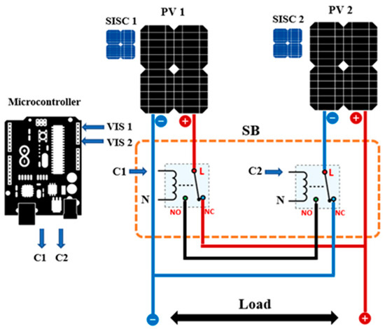
Figure 1.
Switching block.
The operation of the proposed system is as follows. Under normal conditions, when both PV panels receive roughly equal solar radiation without any shading, the relays stay in their default state, which is normally a closed position. In this state, the two panels are connected in parallel; for example, V1 equals V2, where V1 and V2 represent the output voltages of the two PV panels. The switching block’s output voltage and current are illustrated in Table 1.

Table 1.
The action mechanism of the SB block.
However, if one of the PV panels is shaded, it will generate a lower output voltage than the other, falling below the threshold value. The relay attached to the shaded solar panel will then switch to the normally open position, disconnecting the shaded panel. Even when a shaded panel is detached from the array, it continues to generate an electrical current, which is drained through the relays. This prevents the shaded panel from acting as an electrical load on the unshaded panel, thereby avoiding voltage surges and power loss across the other panels that could potentially cause damage. Moreover, PS can elevate the temperatures of shaded solar cells, accelerating their aging process. In the event that both PV panels are shaded, their output voltage will drop below the preset threshold.
The relays will then switch to the normally open position, connecting the panels in series. While this increases the overall output voltage, it can help maintain the output current. For instance, I1 equals I2, where I1 and I2 represent the output currents of the two PV panels. Table 1 effectively illustrates the behavior of the SB block under various operating conditions.
Where Ci, i ∈ {1,2}, stands for the control function executed by the microcontroller. If Ci = 0, then the relay is normally closed. If Ci = 1, the relay is normally open.
The suggested system incorporates blocking diodes for each solar cell panel to avert reverse currents from flowing into shaded or low-voltage solar cells. However, it causes a voltage drop of approximately 0.7 volts. The PV arrays can be expanded by hierarchically adding SBs, facilitating easy and efficient scalability. To create an array of PV panels, the proposed SB connection system is applied to each pair of PV panels. An array of 9 PV panels was proposed by using eight SB modules to connect each of the nine PV panel pairs at three levels in a hierarchical manner. In the first level, five SBs are used, one block for each pair of solar cells. The SB of the ninth cell is connected to the SB of the seventh and eighth solar cells, as shown in Figure 2. The second level consists of two SBs, to which the switch blocks of the first level are connected. The third and final level consists of one switch block, to which the two switch blocks of the second level are connected. This results in an integrated hierarchical structure.
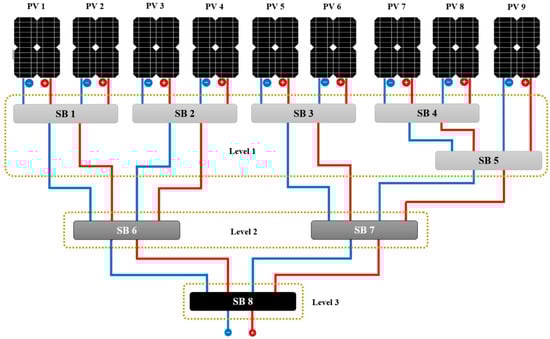
Figure 2.
Nine PV panels are linked with eight SB modules in the hierarchy structure.
Our proposed system employs a pair of Arduino Uno microcontrollers, each featuring 6 analog inputs and 14 digital outputs. This setup enables us to connect the nine SISC units via the analog inputs and the 16 relays through the digital outputs, as depicted in Figure 2.
The following encapsulates a concise overview of the collaborative functionality between the controller and the switching block within the framework of the proposed system. As shown in Figure 3, upon initialization, the microcontroller enters a standby mode, awaiting an input signal from the SISC unit. Once the sensor cell unit transmits signals, the microcontroller processes these signals using pre-programmed mathematical calculations. It then compares the processed signal value with a preset threshold value. If the processed signal value exceeds the threshold, the signal is disregarded, and the relay remains in its default state, which is normally closed. Conversely, if the processed signal value falls below the threshold, the microcontroller triggers the relay to switch from its default state to normally open. This switching mechanism alters the connection configuration between the two solar panels from parallel to series, as detailed in Table 1. This configuration change is contingent on the signal value being less than the threshold value.
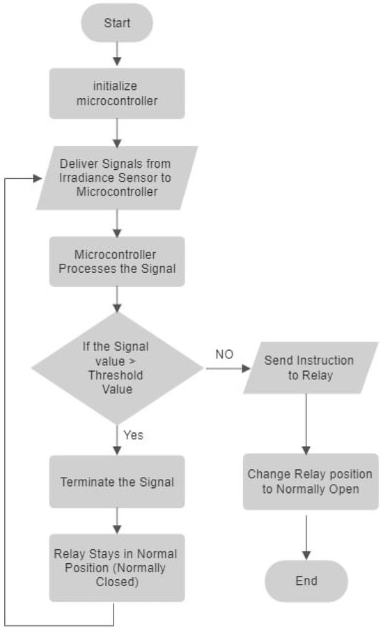
Figure 3.
Flow chart of the proposed SB system.
Solar PV System Modeling
The study employed MATLAB–Simulink version R2021b for the proposed system modeling and analysis. A detailed model of the system was developed in Simulink, incorporating elements such as photovoltaic panels with nonlinear I–V characteristics, relays represented by SBs, and control algorithms implemented through microcontroller functions. The model sends signals representing solar irradiation to the Arduino, and it receives the processed signals to control the SBs. Figure 4 illustrates the proposed system in MATLAB–Simulink.
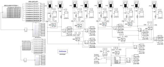
Figure 4.
Proposed system in a MATLAB–Simulink environment.
A consistent temperature of 25 °C was established. The attributes of the solar PV system are outlined in Table 2, and the configuration of the parameters for the solar PV array is depicted in Figure 5.
Table 2.
Specifications of PV panels.
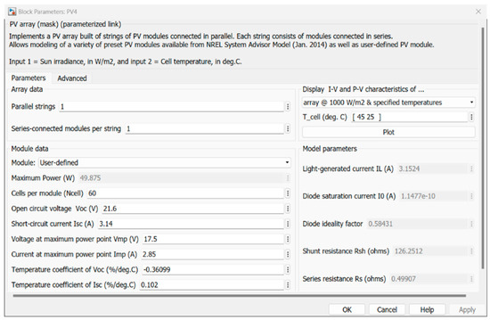
Figure 5.
Configuring the parameters as outlined in Table 2.
The illustration in Figure 6 displays the configuration for the optimal switch, which has a loss in voltage in ON status. The ideal switch acts as a relay and is used in SBs.
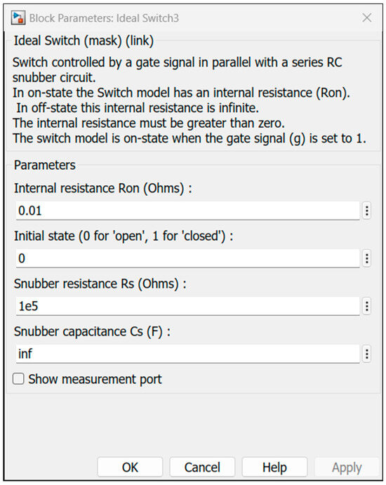
Figure 6.
Simulink idea switch with loss parameter.
4. Simulation Results and Discussion
4.1. System Parameter
The proposed SB-based hierarchical scheme was used to control a nine panel PV array (3 × 3) that was built in a MATLAB–Simulink environment using 50 W PV panels and eight SB modules. The details of the PV panel specifications are outlined in Table 2.
Without sacrificing generality, the nine PV panels are positioned in a singular row, subject to various shading patterns. As outlined in Section 3, a PV panel is considered shaded if its output falls below a predetermined threshold; otherwise, it is considered unshaded.
To find the threshold limit, the level of solar irradiance and voltage for the different shading cases were measured for SISC, as shown in Figure 7. In mid-October of this year (2023), the irradiance in the Iraq/Kirkuk region was measured to reach 720 W/m2 during peak hours under non-shading conditions. The coordinates of the location are 35.466633 latitude and 44.379889 longitude. Figure 7 illustrates the linear relationship between irradiance and the generated voltage, making the latter a reliable estimate for the imposed irradiance and, hence, the shading level. The details of the SISC specifications are outlined in Table 3, while the multimeter specifications are presented in Table 4.
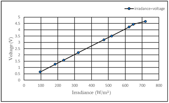
Figure 7.
Relationship between voltage and solar irradiance.
Table 3.
Specifications of the SISC module.
Table 4.
UT89X Digital Multimeter specifications.
PS can increase the temperature of shaded PV panels that are in contact with unshaded panels. This can lead to faster cell aging. Therefore, we recommend disconnecting the weak board from the system to prolong its lifespan and efficiency.
Numerous shading cases exist, including standard patterns SP, BL, and TCT. Table 3 presents the tested shading cases, utilizing various irradiance values (600, 480, 360, 120, 80, and 720 W/m2 for unshaded panels) to monitor MPPT performance.
4.2. PS Cases
The experiment conducted tested 18 different shading scenarios, as illustrated in Figure 8, and it turned out that for every number of shaded panels, there are numerous equivalent shading patterns. This indicates that regardless of the number of shaded panels, there are several shading patterns that have the same impact on the performance of the matrix. This is due to the symmetrical nature of the PV array design and layout. For example, in the partially shaded (PS) case, where one PV panel is shaded while the other eight remain unshaded, the equivalence holds for all combinations in which one PV panel is shaded, without consideration for the specific location of the shaded panel. This means that the effect on array performance is the same whether the shaded panel is at one end of the array, in the middle, or elsewhere. These point to the fact that the symmetrical design of the PV array leads to identical effects from different shading patterns.
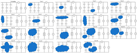
Figure 8.
Patterns of shading on the solar PV array.
In instances of partial shading, solar radiation decreases from 720 W/m2 to 80 W/m2 at a temperature of 25 °C, as depicted in Figure 9.
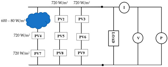
Figure 9.
Reduced solar irradiance when shading occurs on the PV array.
4.3. Results
Table 5 presents the maximum power in watts achieved through a comparative analysis of the proposed system with conventional systems, namely SP, BL, and TCT, under the influence of 18 distinct shading scenarios. The discerned outcomes unequivocally establish the superior performance of the proposed system across the majority of shading instances in comparison to the referenced systems.
Table 5.
Cases of PS and the MPPT in the hierarchical nine panel PV array based on SB.
Figure 10 compares the performance of different PV array configurations under varying shading conditions. The proposed SB scheme consistently delivers higher normalized MPPT values even in challenging shading conditions, indicating improved energy harvesting efficiency.
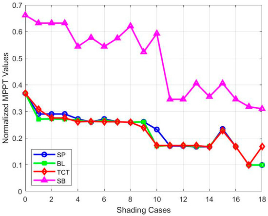
Figure 10.
Comparison of normalized MPPT values for different configurations.
The equations derived for the proposed system, which theoretically calculate the total output voltage, current, and power for different shading scenarios, are presented in Table 6.
Table 6.
The equations for the total output voltage and current in the SB-based hierarchical configuration for the nine PV arrays.
5. Discussion
Simulation results highlight the effectiveness of the proposed method in maximizing energy harvest. For simple shading patterns where one or two PV panels are shaded out of a total of nine panels in the simulated array, in cases one, two, and three, the proposed system demonstrated a 2.13% increase in energy percentage compared to an average of TCT, SP, and BL configurations. For cases five, seven, and eight, there was a 2.5% increase in power. Cases four, six, and sixteen showed marginal increases of approximately 0.5% and 0.8%, respectively. Notably, cases 13 and 14 exhibited substantial increases of 3.2% and 1.5% over traditional configurations, respectively. The proposed system excelled in cases 10 and 17, boasting significant increases of 7.6% and 13.2%, respectively. In case 18, the proposed system outperformed SP and LP configurations by 15.9%, although it lagged behind TCT by 4%. For cases nine, eleven, and twelve, minimal differences were observed in acquired energy values with the proposed system, indicating close performance. In case 15, the average of three traditional configurations surpassed the proposed system by 3%. Figure 11 presents a comparative analysis of the energy harvested by the proposed system and the three configurations under various shading patterns. Moreover, the results affirm the effectiveness and high efficiency of the proposed system, attributed to the hierarchical switching blocks that streamline the system, reducing the number of switches, electrical connections, and sensors during the integration of additional solar units for scalability and growth requirements. Moreover, the system’s management control operations contribute to safeguarding solar panels against rapid damage, aging, and the direct adverse impact of shaded panels on PV arrays. Finally, the integration of a solar radiation sensor cell into the proposed system enhances its accuracy and reliability. This system is classified as an isolated system, characterized by the absence of a direct physical connection between the microcontroller and the solar panels. One of the key features of such a system is its ability to significantly reduce noise and distortions in the data, thereby achieving near-ideal conditions and preventing signal interference between the primary and secondary circuits. In contrast, similar systems exhibit a direct physical connection between the controller and the solar cell. These types of systems necessitate the addition of numerous electronic components to prevent the occurrence of reverse currents. This can impact the system’s operational accuracy and stability, leading to inefficiency. Thus, the proposed system’s design offers a distinct advantage in terms of performance and reliability.
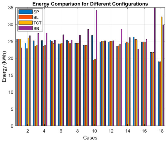
Figure 11.
Comparative energy harvesting in varied shading for proposed and traditional PV configurations.
5.1. Power Generation Performance
The proposed system underwent a comparative analysis concerning its maximum power performance in PS scenarios, juxtaposed with an alternative dynamic system as referenced in [41]. The findings revealed that the proposed system consistently surpassed the dynamic system cited in [41] across all shading instances, alongside its superiority over the Sudoku system. The detailed results of this comparison are elucidated in Table 7 for three distinct shading scenarios. The proposed system SB demonstrably outperforms other methods in both power output and efficiency across all three shading scenarios analyzed, as shown in Figure 12 and Figure 13.
Table 7.
Comparison table for three different scenarios of partial shading.
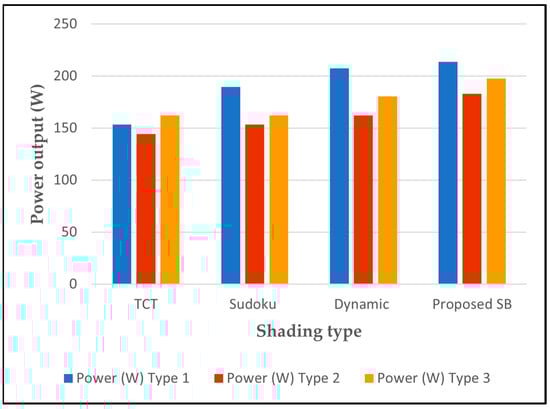
Figure 12.
Power output for different shading types.
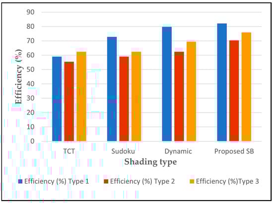
Figure 13.
Efficiency output for different shading types.
Compared to the traditional TCT system, the proposed SB demonstrates an impressive increase in power generation of 21.6% to 39.33% and an improvement in efficiency ranging from 12.9% to 39.32%. It also outperforms the Sudoku system, showing a superiority of 12.8% to 21.6% in power and 12.6% to 21.63% in efficiency. Even against the dynamic system, the proposed SB maintains a clear lead, offering a 3.1% to 12.6% increase in power and a 3% to 12.6% improvement in efficiency. These consistent and significant gains confirm the effectiveness of the proposed SB in optimizing PV system performance under diverse PS conditions, as shown in Figure 14 for power generation and Figure 15 for efficiency.
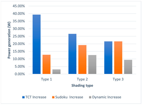
Figure 14.
Power generation enhancement with the proposed SB compared to TCT, Sudoku, and dynamic systems.
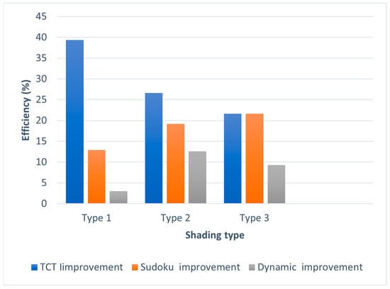
Figure 15.
Efficiency improvement in PV systems: performance analysis of the proposed SB against various configurations.
Furthermore, to validate the proposed system’s efficiency, a comprehensive comparison was conducted with a comparable system from prior research [42]. The results were impressive, with SB significantly surpassing its competitor, particularly relevant for low-power photovoltaic arrays. Table 8 provides a detailed breakdown of SB’s performance across diverse shading scenarios (short–narrow, long–wide, short–wide, and long–narrow). As Figure 16 and Figure 17 illustrate, SB demonstrably outperforms other methods in both power output and efficiency across all four scenarios analyzed.
Table 8.
Comparison table for four different cases of partial shading.
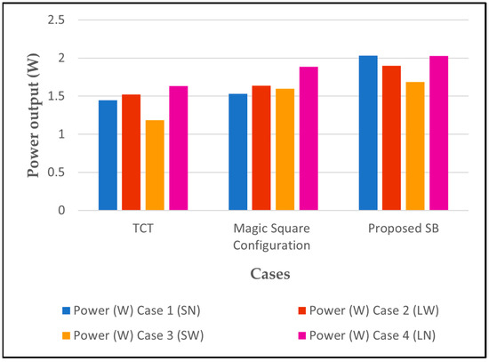
Figure 16.
Power output for different shading cases.
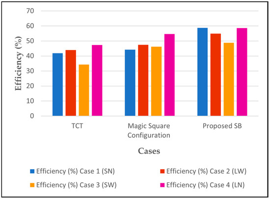
Figure 17.
Efficiency output for different shading cases.
Compared to the traditional TCT system, the proposed SB exhibits an impressive 32.39% to 42.52% increase in power generation and a 31.17% to 42.13% improvement in efficiency. It also surpasses the Magic Square system by a 7.53% to 19.61% increase in power generation and a 5.51% to 32.08% improvement in efficiency. These consistent and significant gains confirm the effectiveness of the proposed SB in optimizing PV system performance under diverse PS conditions.
5.2. Scaling
The proposed system utilizes additional units of the same design of two PV arrays without requiring software updates or hardware modifications to the two PV controllers in terms of input and output lines and is easily expanded. In contrast, the dynamic system demands hardware modifications, including an expanded switch matrix (sw = n × n → (n + 1) × (n + 1)), additional output lines for switch control, and increased input lines for additional sensors. Software updates are also necessary for the dynamic system to accommodate the expanded hardware configuration.
6. Conclusions
This paper introduces a reconfiguration technique for PV arrays. The technique utilizes a hierarchical structure based on a switching block to optimize the maximum power output under PS conditions. The system, controlled by a microcontroller and equipped with a SISC module, dynamically reconfigures the PV array to maximize power extraction under varying shading conditions. The switching block alters the connection state between the solar panels, switching between parallel and series connections based on a predetermined threshold value. The performance of this technique was evaluated using MATLAB–Simulink, and the results demonstrated that the proposed reconfiguration strategy offers better performance compared to the SP, BL, TCT, Sudoku, the dynamic proposal from reference [41], and Magic Square from reference [42] under similar partial shade conditions. Furthermore, the proposed strategy effectively reduces losses, enhances efficiencies, and improves the overall performance of PV arrays during partial shading. One of the key advantages of the system’s hierarchical structure is the ease of array expansion. Additional solar panels can be seamlessly integrated into the PV array without complications in design or the need for re-establishing electrical connections. The results showed the proposed SB consistently outperforms, with increases in power generation (21.6% to 39.33%) and efficiency (21.63% to 39.32%). It also outperforms other systems, including Sudoku and a dynamic proposal, confirming its superiority in optimizing PV system performance. Furthermore, the proposed SB exhibits significant gains when compared to the TCT and Magic Square systems, with a remarkable increase in power generation (32.39% to 42.52%) and efficiency (31.17% to 42.13%). These high-value results underscore the efficiency of the proposed SB in optimizing PV system performance under various PS conditions. In the future, we plan to investigate the impact of different switching block configurations and optimization algorithms on system performance through real-world testing.
Author Contributions
Conceptualization, A.S. and F.A.; formal analysis, F.A. and A.S.; funding acquisition, A.T. and R.B.; methodology, A.S. and F.A.; software, F.A.; supervision, A.T. and A.S.; visualization, F.A.; writing—original draft, A.S. and F.A.; writing—review and editing, F.A., A.S., A.T. and R.B. Invited author, R.B. All authors have read and agreed to the published version of the manuscript.
Funding
This research received no external funding.
Data Availability Statement
The data presented in this research are available by contacting the corresponding author upon request.
Acknowledgments
The authors express their gratitude to the University of Miskolc and the Institute of Automation and Info-Communication.
Conflicts of Interest
The authors declare no conflicts of interest.
References
- Kabeyi, M.J.B.; Olanrewaju, O.A. Sustainable Energy Transition for Renewable and Low Carbon Grid Electricity Generation and Supply. Front. Energy Res. 2022, 9, 1032. [Google Scholar] [CrossRef]
- Green, M.A.; Hishikawa, Y.; Dunlop, E.D.; Levi, D.H.; Hohl-Ebinger, J.; Yoshita, M.; Ho-Baillie, A.W.Y. Solar Cell Efficiency Tables (Version 53). Prog. Photovolt. Res. Appl. 2019, 27, 3–12. [Google Scholar] [CrossRef]
- Yang, B.; Yu, T.; Zhang, X.; Li, H.; Shu, H.; Sang, Y.; Jiang, L. Dynamic Leader Based Collective Intelligence for Maximum Power Point Tracking of PV Systems Affected by Partial Shading Condition. Energy Convers. Manag. 2019, 179, 286–303. [Google Scholar] [CrossRef]
- Rahman, T.; Mansur, A.A.; Hossain Lipu, M.S.; Rahman, M.S.; Ashique, R.H.; Houran, M.A.; Elavarasan, R.M.; Hossain, E. Investigation of Degradation of Solar Photovoltaics: A Review of Aging Factors, Impacts, and Future Directions toward Sustainable Energy Management. Energies 2023, 16, 3706. [Google Scholar] [CrossRef]
- Balato, M.; Costanzo, L.; Vitelli, M. Reconfiguration of PV Modules: A Tool to Get the Best Compromise between Maximization of the Extracted Power and Minimization of Localized Heating Phenomena. Sol. Energy 2016, 138, 105–118. [Google Scholar] [CrossRef]
- Ziar, H.; Mansourpour, S.; Afjei, E.; Kazemi, M. Bypass Diode Characteristic Effect on the Behavior of Solar PV Array at Shadow Condition. In Proceedings of the 2012 3rd Power Electronics and Drive Systems Technology (PEDSTC), Tehran, Iran, 15–16 February 2012; pp. 229–233. [Google Scholar] [CrossRef]
- Satpathy, P.R.; Jena, S.; Sharma, R. Power enhancement from partially shaded modules of solar PV arrays through various interconnections among modules. Energy 2018, 144, 839–850. [Google Scholar] [CrossRef]
- Satpathy, P.R.; Sharma, R. Power and Mismatch Losses Mitigation by a Fixed Electrical Reconfiguration Technique for Partially Shaded Photovoltaic Arrays. Energy Convers. Manag. 2019, 192, 52–70. [Google Scholar] [CrossRef]
- Zhu, Z.; Hou, M.; Ding, L.; Zhu, G.; Jin, Z. Optimal Photovoltaic Array Dynamic Reconfiguration Strategy Based on Direct Power Evaluation. IEEE Access 2020, 8, 210267–210276. [Google Scholar] [CrossRef]
- Storey, J.; Wilson, P.R.; Bagnall, D. The Optimized-String Dynamic Photovoltaic Array. IEEE Trans. Power Electron. 2014, 29, 1768–1776. [Google Scholar] [CrossRef]
- Vicente, P.D.S.; Pimenta, T.C.; Ribeiro, E.R. Photovoltaic Array Reconfiguration Strategy for Maximization of Energy Production. Int. J. Photoenergy 2015, 2015, 592383. [Google Scholar] [CrossRef]
- Gadiraju, H.K.V.; Barry, V.R.; Jain, R.K. Improved Performance of PV Water Pumping System Using Dynamic Reconfiguration Algorithm under Partial Shading Conditions. CPSS Trans. Power Electron. Appl. 2022, 7, 206–215. [Google Scholar] [CrossRef]
- Yousri, D.; Allam, D.; Eteiba, M.B.; Suganthan, P.N. Static and Dynamic Photovoltaic Models’ Parameters Identification Using Chaotic Heterogeneous Comprehensive Learning Particle Swarm Optimizer Variants. Energy Convers. Manag. 2019, 182, 546–563. [Google Scholar] [CrossRef]
- Rezk, H.; AL-Oran, M.; Gomaa, M.R.; Tolba, M.A.; Fathy, A.; Abdelkareem, M.A.; Olabi, A.G.; El-Sayed, A.H.M. A Novel Statistical Performance Evaluation of Most Modern Optimization-Based Global MPPT Techniques for Partially Shaded PV System. Renew. Sustain. Energy Rev. 2019, 115, 109372. [Google Scholar] [CrossRef]
- Rezazadeh, S.; Moradzadeh, A.; Hashemzadeh, S.M.; Pourhossein, K.; Mohammadi-Ivatloo, B.; Hosseini, S.H. A novel prime numbers-based PV array reconfiguration solution to produce maximum energy under partial shade conditions. Sustain. Energy Technol. Assess 2021, 47, 101498. [Google Scholar] [CrossRef]
- Anjum, S.; Mukherjee, V. Static and Dynamic Reconfiguration Strategies for Reducing Partial Shading Effects in Photovoltaic Array: A Comprehensive Review. Energy Technol. 2022, 10, 2200098. [Google Scholar] [CrossRef]
- Caruso, M.; Miceli, R.; Romano, P.; Schettino, G.; Spataro, C.; Viola, F. A Low-Cost, Real-Time Monitoring System for PV Plants Based on ATmega 328P-PU Microcontroller. In Proceedings of the 2015 IEEE International Telecommunications Energy Conference (INTELEC), Osaka, Japan, 18–22 October 2015. [Google Scholar] [CrossRef]
- Aljafari, B.; Satpathy, P.R.; Thanikanti, S.B. Partial shading mitigation in PV arrays through dragonfly algorithm based dynamic reconfiguration. Energy 2022, 257, 124795. [Google Scholar] [CrossRef]
- Palpandian, M.; Winston, D.P.; Kumar, B.P.; Kumar, C.S.; Babu, T.S.; Alhelou, H.H. A New Ken-Ken Puzzle Pattern Based Reconfiguration Technique for Maximum Power Extraction in Partial Shaded Solar PV Array. IEEE Access 2021, 9, 65824–65837. [Google Scholar] [CrossRef]
- Deshkar, S.N.; Dhale, S.B.; Mukherjee, J.S.; Babu, T.S.; Rajasekar, N. Solar PV Array Reconfiguration under Partial Shading Conditions for Maximum Power Extraction Using Genetic Algorithm. Renew. Sustain. Energy Rev. 2015, 43, 102–110. [Google Scholar] [CrossRef]
- Fathy, A. Recent Meta-Heuristic Grasshopper Optimization Algorithm for Optimal Reconfiguration of Partially Shaded PV Array. Sol. Energy 2018, 171, 638–651. [Google Scholar] [CrossRef]
- Babu, T.S.; Ram, J.P.; Dragičević, T.; Miyatake, M.; Blaabjerg, F.; Rajasekar, N. Particle swarm optimization based solar PV array reconfiguration of the maximum power extraction under partial shading conditions. IEEE Trans. Sustain. Energy 2018, 9, 74–85. [Google Scholar] [CrossRef]
- Babu, T.S.; Yousri, D.; Balasubramanian, K. Photovoltaic Array Reconfiguration System for Maximizing the Harvested Power Using Population-Based Algorithms. IEEE Access 2020, 8, 109608–109624. [Google Scholar] [CrossRef]
- Siddiq, A.I.; Fadhel, H.N.; Anwar, M.O. Automatic PV Array Reconfiguration under Partial Shading Conditions. Abdulrahman Ikram Siddiq/NTU J. Renew. Energy 2023, 4, 36–46. [Google Scholar] [CrossRef]
- Srinivasan, A.; Devakirubakaran, S.; Sundaram, B.M.; Balachandran, P.K.; Cherukuri, S.K.; Winston, D.P.; Babu, T.S.; Alhelou, H.H. L-Shape Propagated Array Configuration with Dynamic Reconfiguration Algorithm for Enhancing Energy Conversion Rate of Partial Shaded Photovoltaic Systems. IEEE Access 2021, 9, 97661–97674. [Google Scholar] [CrossRef]
- Murtaza, A.F.; Sher, H.A. A Reconfiguration Circuit to Boost the Output Power of a Partially Shaded PV String. Energies 2023, 16, 622. [Google Scholar] [CrossRef]
- Hussein, H.; Mahdi, A.; Abdul-Wahhab, T. Design of a Boost Converter with MPPT Algorithm for a PV Generator Under Extreme Operating Conditions. Eng. Technol. J. 2021, 39, 1473–1480. [Google Scholar] [CrossRef]
- Noman, A.M.; Sheikh, H.S.; Murtaza, A.F.; Almutairi, S.Z.; Alqahtani, M.H.; Aljumah, A.S. Maximum Power Point Tracking Algorithm of Photo-Voltaic Array through Determination of Boost Converter Conduction Mode. Appl. Sci. 2023, 13, 8033. [Google Scholar] [CrossRef]
- Jamaludin, M.N.I.; Tajuddin, M.F.N.; Ahmed, J.; Azmi, A.; Azmi, S.A.; Ghazali, N.H.; Babu, T.S.; Alhelou, H.H. An Effective Salp Swarm Based MPPT for Photovoltaic Systems under Dynamic and Partial Shading Conditions. IEEE Access 2021, 9, 34570–34589. [Google Scholar] [CrossRef]
- Muhammad Ajmal, A.; Ramachandaramurthy, V.K.; Naderipour, A.; Ekanayake, J.B. Comparative Analysis of Two-Step GA-Based PV Array Reconfiguration Technique and Other Reconfiguration Techniques. Energy Convers. Manag. 2021, 230, 113806. [Google Scholar] [CrossRef]
- Namuq, K.A.; Siddiq, A.I.; Abdulkader, H. Dynamic Reconfiguration of PV Array under Partial Shading Condition by Using Automatic Switching. Int. J. Electr. Electron. Eng. Telecommun. 2023, 12, 272–278. [Google Scholar] [CrossRef]
- Yousri, D.; Thanikanti, S.B.; Balasubramanian, K.; Osama, A.; Fathy, A. Multi-Objective Grey Wolf Optimizer for Optimal Design of Switching Matrix for Shaded Pv Array Dynamic Reconfiguration. IEEE Access 2020, 8, 159931–159946. [Google Scholar] [CrossRef]
- Rezk, H.; Fathy, A.; Aly, M. A Robust Photovoltaic Array Reconfiguration Strategy Based on Coyote Optimization Algorithm for Enhancing the Extracted Power under Partial Shadow Condition. Energy Rep. 2021, 7, 109–124. [Google Scholar] [CrossRef]
- Harrag, A.; Messalti, S. Adaptive GA-Based Reconfiguration of Photovoltaic Array Combating Partial Shading Conditions. Neural Comput. Appl. 2018, 30, 1145–1170. [Google Scholar] [CrossRef]
- Abdalla, O.; Rezk, H.; Ahmed, E.M. Wind Driven Optimization Algorithm Based Global MPPT for PV System under Non-Uniform Solar Irradiance. Sol. Energy 2019, 180, 429–444. [Google Scholar] [CrossRef]
- Mirza, A.F.; Mansoor, M.; Ling, Q.; Yin, B.; Javed, M.Y. A Salp-Swarm Optimization based MPPT technique for harvesting maximum energy from PV systems under partial shading conditions. Energy Convers. Manag. 2020, 209, 112625. [Google Scholar] [CrossRef]
- Sharma, D.; Jalil, M.F.; Ansari, M.S.; Bansal, R.C. A Review of PV Array Reconfiguration Techniques for Maximum Power Extraction Under Partial Shading Conditions. Optik 2023, 275, 170559. [Google Scholar] [CrossRef]
- Hou, S.; Zhu, W. Dynamic Reconfiguration Method of Photovoltaic Array Based on Improved HPSO Combined with Coefficient of Variation. Electronics 2023, 12, 2744. [Google Scholar] [CrossRef]
- Mostafaee, G.; Ghandehari, R. Power Enhancement of Photovoltaic Arrays under Partial Shading Conditions by a New Dynamic Reconfiguration Method. Res. Artic. J. Energy Manag. Technol. 2019, 4, 46. [Google Scholar] [CrossRef]
- Fang, X.; Yang, Q.; Yan, W. Switching Matrix Enabled Optimal Topology Reconfiguration for Maximizing Power Generation in Series-Parallel Organized Photovoltaic Systems. IEEE Syst. J. 2022, 16, 2765–2775. [Google Scholar] [CrossRef]
- Hariharasudhan, T.; Suriyakala, S.; Prince, W.D.; Sathya, P. Dynamic and Static Reconfiguration Analysis of Solar PV Array. Ymer J. 2022, 21, 204–208. [Google Scholar] [CrossRef]
- Rakesh, N.; Malavya, U. Maximizing the Power Output of Partially Shaded Solar PV Array using Novel Interconnection Method. In Proceedings of the International Conference on Innovative Mechanisms for Industry Applications (ICIMIA 2017), Bengaluru, India, 21–23 February 2017. [Google Scholar] [CrossRef]
Disclaimer/Publisher’s Note: The statements, opinions and data contained in all publications are solely those of the individual author(s) and contributor(s) and not of MDPI and/or the editor(s). MDPI and/or the editor(s) disclaim responsibility for any injury to people or property resulting from any ideas, methods, instructions or products referred to in the content. |
© 2023 by the authors. Licensee MDPI, Basel, Switzerland. This article is an open access article distributed under the terms and conditions of the Creative Commons Attribution (CC BY) license (https://creativecommons.org/licenses/by/4.0/).