Abstract
This paper presents a comprehensive model predictive control (CMPC) method to control a three-phase four-legged inverter (TP4LI) for PV systems. The proposed TP4LI model aims to predictively model and control switching frequency and higher voltage/current switching to reduce losses. The CMPC model can be operated in four modes, namely standard MPC mode (Mode I), switching frequency reduction (SFR) mode (Mode II), high voltage/current switching loss reduction (SLR) mode (Mode III), and SFR plus SLR mode (Mode IV, a combination of Modes II and III). The proposed CMPC approach controls the TP4LI to (1) successfully track balanced and unbalanced reference currents with balanced or unbalanced loads; (2) reduce switching losses; and (3) keep the generated current total harmonic distortion (THD) within the industry’s recommended limits. The TP4LI model with the CMPC approach was verified and validated in the MATLAB/Simulink for a PV system. The simulation results show good tracking and performance of the TP4LI for balanced and unbalanced reference currents with balanced and unbalanced loads in all four modes of operation.
1. Introduction
Inverters are used to connect renewable energy systems (wind, PV, etc.) to a grid [1,2] since they convert DC power into AC power for loading and/or injection into the grid. Inverters can be single-, two-, or three-phase, with three-phase inverters being three- or four-legged. Three-legged inverters are used for balanced three-phase loads, while four-legged inverters are used for balanced three-phase as well as unbalanced three-phase loads and injection into the grid. Three-phase three-legged inverter has a total of 8 possible switching states (23 = 8), while a three-phase four-legged inverter (TP4LI) has 16 (24 = 16) possible switching states due to an additional fourth leg. The fourth leg adds a neutral current-carrying capability to the inverter, extending the inverter’s use for unbalanced load in addition to balanced load.
The literature has a rich repository on all kinds of inverter control techniques. A review of control techniques for single-phase inverters is presented by [3,4], and a review of control techniques for three-phase inverters is presented by [5,6]. Repetitive control is reported by [7,8], sliding mode is reported by [9,10], dead-beat control is reported by [11,12], synchronous reference frame is reported by [13], sine pulse-width modulation is reported by [14,15], standard space-vector pulse-width modulation is reported by [16,17], and high-current, not-switched space-vector pulse-width modulation is reported by [18]. However, the studies by [7,8] suffer from poor tracking accuracy and large memory requirement with poor non-periodic disturbance rejection ability [13]. Sliding mode [9,10] and dead-beat control [11,12] are complex and sensitive to parameter variations and suffer from varying loading conditions. PI regulators used in synchronous reference frame [13] controls require regulator adjustments and have poor disturbance rejection capability. Sine pulse-width modulation [14,15] control needs a carrier and modulating wave generation and cannot exploit the full potential of the DC source. Space-vector pulse-width modulation [16,17,18] is complex and time-consuming due to exhaustive vector calculations, and it is non-intuitive for software/hardware implementation [19,20].
Model predictive control (MPC) is simple and intuitive and eliminates modulation stages and linear regulators [21,22,23]. MPC flexibility allows the incorporation of a system’s nonlinearities and limitations into the model, resulting in a better steady state and faster transient response when compared to traditional controllers [24,25,26]. MPC used for a multitude of applications in renewable energy systems is reported in the literature. The use of MPC for energy dispatch problems in electrical energy systems with many intermittent renewable resources is reported by [27]. The use of MPC for economic optimization of PV plants with energy storage is presented by [28]. The use of MPC for resource coordination in renewable energy-based microgrids is reported by [29]. Recently, MPC is used for inverter control in a system’s model to predict and control the future behavior of the inverter [30,31], using both present and past data.
A review of MPC application in power converters is presented by Ref. [32]. MPC of a three-phase inverter is compared against hysteresis and pulse-width modulation control techniques in [31]. MPC’s superiority in terms of harmonics is reported by [33]. A unified DC and AC side control for PV systems using MPC by predicting the output current based on the PV potential of the PV array on the DC side is presented by [34]. MPC of a utility-interactive single-phase inverter is reported by [35] and of a utility-interactive seven-level single-phase inverter by [36]. The control of active and reactive power using MPC is reported by [37]. Low switching frequency MPC of a three-phase module integrated with DC voltage boost capability and control of active and reactive power with low voltage ride through capability is examined by [38]. However, none of the above studies has investigated, modeled, and reported switching frequency (SFR) and higher voltage–current switching loss reduction (SLR) based on a comprehensive MPC for a TP4LI.
Ref. [39] proposed a model-predictive direct power control strategy for flexible power regulation of a grid-tied inverter that is used in PV systems with a switching frequency reduction algorithm. However, this study did not focus on high voltage–current switching to reduce losses. Its focus was a three-legged inverter, which is good for balanced loads only. Refs. [20,21,40] proposed an MPC strategy for a two-level four-legged inverter to deliver power to grids with balanced and unbalanced loads but without high voltage–current state-switching loss reduction. Ref. [41] proposed a diode rectifier-based three-level boost converter with a neutral-point-clamped inverter. However, switching frequency reduction is limited to the neutral leg only for the neutral-point-clamped inverter. Additionally, high voltage–current state-switching loss reduction is not the focus. Ref. [42] proposed an MPC for optimal switching reduction calculations by preselecting five possible switching combinations, and [43] proposed a current-limiting MPC in which any switching combination producing higher than the desired current is excluded from the list of prospective switching options in the next interval. Although successful in achieving their goals, [42,43] did not report switching frequency and high voltage–current switching loss reduction based on an MPC for a TP4LI.
This paper proposes switching frequency reduction (SFR) and high voltage–current switching loss reduction (SLR) using a comprehensive MPC (CMPC) for a TP4LI. The CMPC is used to control the TP4LI in four modes, namely (1) MPC-only mode (Mode I), (2) SFR mode (Mode II), (3) SLR mode (Mode III), and (4) SFR plus SLR mode (Mode IV) with balanced and unbalanced reference currents and loads. The rest of the paper is organized as follows: (Section 1) introduction of the TP4LI model; (Section 2) materials and methods; (Section 3) results and discussions; and (Section 4) conclusions.
The novelty and main objectives of the proposed CMPC, besides the inherent MPC advantages, are to provide a simple yet intuitive control model for a TP4LI that is (A) decoupled to independently minimize losses associated with (1) switching frequency or (2) high voltage–current switching and yet (B) integrative to minimize losses associated both with A(1) and A(2) simultaneously, while (C) keeping the harmonics under industry standard limits [44,45]. The proposed method is an MPC, which inherently draws on the strengths of MPC and, thus, boasts small memory requirement, computational speed, simplicity, parameter robustness, good performance, and no carrier/modulating wave generation requirements, as discussed in the second paragraph of this section.
2. Materials and Methods
The model predictive control (MPC) strategy takes advantage of the fact that only a finite number of possible switching states are associated with a three-phase four-legged inverter (TP4LI). These states are discrete, and the model of the TP4LI can be used in association with a discrete-time model of the load to predict the behavior of the system over a prediction horizon (sampling time). The objective of the MPC scheme is to predict the switching state and, thus, the current by tracking the reference (or desired) current with minimum error. For each sampling period, the resulting (predicted) output current () is measured and compared with the reference current () to minimize error. The sampling period (TS) is selected to be small such that the reference current does not change significantly during that period (TS).
Figure 1 shows a TP4LI circuit with a filter inductor (L) and a load resistor (R). The TP4LI has 4 legs with 8 switches. The fourth leg, also known as the neutral leg, enables the independent generation of voltage and current on each of the three phases of the TP4LI. The TP4LI’s 8 switches result in 16 (24) possible switching states, as tabulated in Table 1, with corresponding A-, B-, and C-phase voltages and vectors ranging from 0 to 15. The switches are switched in a controlled manner to connect the A, B, and C terminals to the positive (P) or negative (N) terminals of the DC source (VDC) to generate v and i.
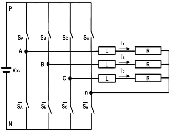
Figure 1.
TP4LI Circuit.

Table 1.
LI Switching States with Corresponding Voltages and Vectors.
The output voltages of the TP4LI are calculated based on Equations (1)–(3):
Similarly, load dynamics are modeled by (4), where L and R are the filter inductance and resistance, i is the current, and v is the TP4LI-generated voltage vector. The current i in (4) can be approximated by (5) using the Euler forward equation, where k is the present interval and k + 1 is the next interval for which the prediction is made.
Equation (6) is the result of (4) and (5), which is further expressed by (7) to exercise the MPC in a αβ reference frame and predict the load current for each switching state of the TP4LI model.
It is evident from (6) (or (7)) that the current prediction requires a definition of the loads v and i. However, defining or changing the switch state from on to off or from off to on state to define v and i causes power loss, and frequent changes in switching states increase these power losses. Hence, switching frequency reduction can improve the TP4LI’s efficiency.
Starting at V0 = 0000 (SASBSCSn sequence) as a present state, there is a total of 15 possible switching paths (V1 to V15), as shown in Table 1. Four switching paths have 1 switch-state change (V1, V2, V4, and V8), 6 switching paths have 2 switch-state changes (V3, V5, V6, V9, V10, and V12), 4 switching paths have 3 switch-state changes (V7, V11, V13, and V14), and 1 switching path has 4 switch-state changes (V15), as shown in Figure 2. This is true for switching paths from any switch-state as a starting status. Thus, power loss reduction is possible if control is implemented such that the minimum number of switches change their states at any time, providing that the TP4LI’s performance is not degraded significantly and the THD is kept within the industry standard limits.
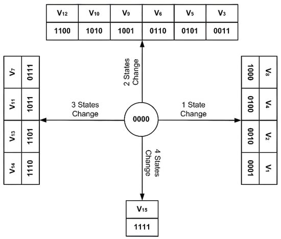
Figure 2.
TP4LI Switch-State Changes.
Switching losses also depend on the magnitudes of the voltage across and the current through the switch at the time of state switching, besides switching frequency. Therefore, the state change of a switch with a higher voltage and a higher current causes a higher power loss compared to the state change of a switch with a lower voltage and a lower current. Hence, switching to a switch state with a lower voltage and current is preferred to reduce further power losses associated with the switches, providing the TP4LI’s performance is not affected and the THD is kept within the industry’s standard limits.
This work proposes the following three objectives to achieve the objectives outlined above:
- (1)
- J1: Minimize the error between the predicted and reference currents as follows:
- (2)
- J2: Minimize the state-change switching frequency of switches:
- (3)
- J3: Change the state of a switch with lower voltage and current with higher priority:
However, these objectives should be achieved while maintaining the performance and the THD of the TP4LI within industry limits, i.e., THD should be less than 5% as per the IEEE 519 standard. These conditions are introduced as constraints in the MPC model. It should be noted that, if the sampling period is small, we do not require extrapolation [20,42,43].
Combining (8)–(10), we obtain the objective function for the proposed MPC method as follows:
Based on the two tuning parameters, λSFR (switching frequency reduction weighting factor) and λSLR (weighting factor for switching losses), we define four modes of operation for the proposed controller:
- Mode I: λSFR = λSLR = 0
Standard MPC operation ignoring J2 and J3. This achieves a reduction in the issues associated with conventional techniques only, as outlined in the 2nd paragraph of Section 1 and as identified by the references cited in the same section.
- Mode II: λSFR ≠ 0 and λSLR = 0
SFR-based MPC operation ignoring J3. In addition to the benefits of Mode I, this mode achieves switching frequency reduction and, thus, minimizes losses due to excessive and unnecessary switching associated with most of the conventional approaches.
- Mode III: λSFR = 0 and λSLR ≠ 0
SLR-based MPC operation ignoring J2. In addition to the benefits of Mode I, this mode achieves high voltage–current switching reduction and, thus, minimizes losses due to switching the switches with a high voltage across and a high current through them, which is again a factor that causes significant losses in most of the conventional approaches.
- Mode IV: λSFR ≠ 0 and λSLR ≠ 0
SFR plus SLR-based MPC operation activating all objectives. This mode combines the benefits of Mode I, Mode II, and Mode III and, thus, boasts (1) a reduction in higher frequency switching losses, (2) a reduction in high voltage–current switching losses, and (3) a reduction in the issues listed in Section 1 that are associated with conventional controllers, while keeping the THD within the industry limits (also attained in the other modes).
The objective function J (11) is evaluated for each of the 16 possible voltage vectors (V0 to V15) generated by the TP4LI. The optimal J with the minimum error between the predicted (present) and measured (past) outputs is selected, and the corresponding control action (switching combination) from a set of control actions (0000 to 1111) is identified to be applied in the next interval (sampling period). The output produced is observed, and the process is repeated to synthesize the optimal control action for the next interval.
3. Results and Discussions
To evaluate the effectiveness of the proposed comprehensive MPC (CMPC) strategy for the TP4LI, we considered a system configuration that consists of a DC source (a PV system), an AC grid, and a 4-wire load. The proposed controller receives the output from the TP4LI and gives the control signal to operate the TP4LI.
The model was simulated multiple times to test the effectiveness of the proposed CMPC model in all four modes of operation: standard MPC (Mode I), SFR (Mode II), SLR (Mode III), and SFR + SLR (Mode IV) with balanced reference currents and balanced loads. Additionally, Mode I for unbalanced reference current tracking and unbalanced loads was also simulated with successful current tracking, although the results are not discussed further in this work. Only selected results are reported to avoid increasing the length of the paper. The parameters used for the simulations are listed in Table 2 (Simulation Parameters). Refs. [46,47,48] were used for switching loss estimations, and readers interested in further readings are referred to these studies for details on switching loss estimation. The weighting factors, λSFR and λSLR, were selected to reduce the losses associated with switching frequency and higher voltage–current switching, while keeping the THD within the industry standard limits.

Table 2.
Simulation Parameters.
Figure 3 shows the responses of the TP4LI in Mode I (MPC with λSFR = λSLR = 0, i.e., standard MPC operation ignoring both J2 and J3) with balanced reference currents. Figure 3 displays the 3-phase voltages, the 3-phase produced currents with 3-phase reference currents, the neutral current, the switching frequency (one duty cycle), and the switching losses for the four legs.

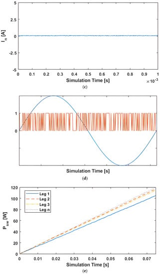
Figure 3.
(a) Vabc-Mode I with Balanced Reference Currents. (b) Iabc-Mode I with Balanced Reference Currents. (c) In-Mode I with Balanced Reference Currents. (d) Switching frequency for one duty cycle-Mode I with Balanced Reference Currents. (e) Switching losses-Mode I with Balanced Reference Currents.
Figure 3a shows that voltage Vabc is perfectly maintained, leading to 3-phase currents (Iabc), which successfully track the balanced reference currents, as shown in Figure 3b, with neutral current (In) maintained at zero, as shown in Figure 3c. The total harmonic distortion (THD) for phase A current (Ia-THD) is 0.06% for this mode.
Moreover, switch S1 of phase A switched 13,488 times (as reported by the switch flipping counter in the model) for the duration of the simulation, with Figure 3d showing the switching frequency (fsw) in one duty cycle. Finally, Figure 3e shows the switching power losses (Psw). The total loss is 431.6 W, with a loss of 08.04 W, 113.77 W, 92.22 W, and 117.61 W for Leg1, Leg2, Leg3, and Legn, respectively, for the duration of the simulation, as shown in Figure 3e.
Figure 4 shows the responses of the TP4LI in Mode II (MPC with λSFR = 0.015 and λSLR = 0, i.e., SFR-based MPC operation ignoring J3) with balanced reference currents. Figure 4 displays the 3-phase voltages, the 3-phase produced currents with 3-phase reference currents, the neutral current, the switching frequency (one duty cycle), and the switching losses for the four legs.

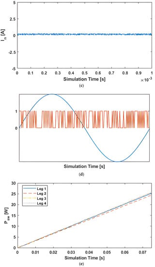
Figure 4.
(a). Vabc-Mode II with Balanced Reference Currents. (b). Iabc-Mode II with Balanced Reference Currents. (c). In-Mode II with Balanced Reference Currents. (d). Switching frequency for one duty cycle-Mode II with Balanced Reference Currents. (e). Switching losses-Mode II with Balanced Reference Currents.
Figure 4a shows that voltage Vabc is perfectly maintained, leading to 3-phase currents (Iabc), which successfully track the balanced reference currents, as shown in Figure 4b, but with increased THD and neutral current (In) greater than zero, as shown in Figure 4c. The total harmonic distortion (THD) measured is 2.11% for phase A current (Ia-THD) for this mode.
However, switch S1 of phase A switched only 3159 times for the duration of the simulation, with Figure 4d showing the switching frequency (fsw) for one duty cycle. Finally, Figure 4e shows the switching power losses (Psw). The loss also decreases to a total of 101.19 W, with a loss of 25.31 W, 24.45 W, 25.63 W, and 25.08 W for Leg1, Leg2, Leg3, and Legn, respectively, for the duration of the simulation, as shown in Figure 4e.
Figure 5 shows the responses of the TP4LI in Mode III (MPC with λSFR = 0 and λSLR = 0.015, i.e., SLR-based MPC operation ignoring J2) with balanced reference currents. Figure 5 displays the 3-phase voltages, the 3-phase produced currents with 3-phase reference currents, the neutral current, the switching frequency (one duty cycle), and the switching losses for the four legs.

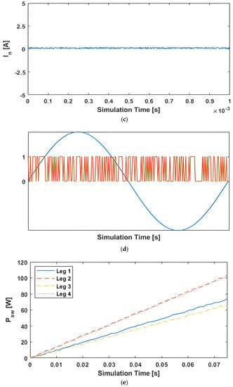
Figure 5.
(a) Vabc-Mode III with Balanced Reference Currents. (b) Iabc-Mode III with Balanced Reference Currents. (c) In-Mode III with Balanced Reference Currents. (d) Switching frequency for one duty cycle-Mode III with Balanced Reference Currents. (e) Switching losses-Mode III with Balanced Reference Currents.
Figure 5a shows that voltage Vabc is perfectly maintained, leading to 3-phase currents (Iabc), which successfully track the balanced reference currents, as shown in Figure 5b. The THD for this mode of operation is lower than Mode II but higher than Mode I. Similarly, the neutral current (In) is greater than zero and higher than Mode I but lower than Mode II, as shown in Figure 5c. The total harmonic distortion (THD) measured is 0.89% for phase A current (Ia-THD) for this mode.
Following the trend, switch S1 of phase A switched only 9195 times (higher than Mode II but lower than Mode I) for the duration of the simulation, with Figure 5d showing the switching frequency (fsw) for one duty cycle. Finally, Figure 5e shows the switching power losses (Psw). The total loss is 345.98 W, with a loss of 73.65 W, 103.53 W, 66.38 W, and 102.42 W for Leg1, Leg2, Leg3, and Legn, respectively, for the duration of the simulation, as shown in Figure 5e.
Note that fsw and Psw are lower than Mode I but higher than Mode II for this mode (Mode III), but the THD is higher than Mode I and lower than Mode II with the same weighting factor of 0.015 (λSFR = λSLR = 0.015). Thus, λSLR has a shallower influence compared to λSFR. In is also noticed to have a smaller change when compared to Mode I and Mode II for λSFR = λSLR = 0.015.
Figure 6 shows the responses of the TP4LI in Mode IV (MPC with λSFR = 0.015 and λSLR = 0.025, i.e., SFR+SLR-based MPC operation including both J2 and J3) with balanced reference currents. Figure 6 displays the 3-phase voltages, the 3-phase produced currents with 3-phase reference currents, the neutral current, the switching frequency (one duty cycle), and the switching losses for the four legs.

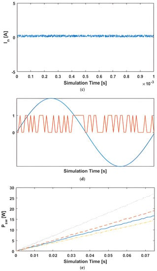
Figure 6.
(a) Vabc-Mode IV with Balanced Reference Currents. (b) Iabc-Mode IV with Balanced Reference Currents. (c) In-Mode 1V with Balanced Reference Currents. (d) Switching frequency for one duty cycle-Mode 1V with Balanced Reference Currents. (e) Switching losses-Mode IV with Balanced Reference Currents.
Figure 6a shows that voltage Vabc is perfectly maintained, leading to 3-phase currents (Iabc), which successfully track the balanced reference currents, as shown in Figure 6b. THD for this mode of operation was measured at 1.84%, which is within the industry limits.
The number of times switch S1 of phase A switched was observed to be 2090, with Figure 6d showing the switching frequency (fsw) for one duty cycle. Finally, the switching power losses (Psw) decrease to a total loss of 77.39 W, with a loss of 16.74 W, 19.10 W, 14.43 W, and 27.12 W for Leg1, Leg2, Leg3, and Legn, respectively, for the duration of the simulations as shown in Figure 6e.
A comparison of Mode IV to Mode I, Mode II, and Mode III is presented in Table 3. The table clearly shows that Mode IV outperforms the other three modes, with significant performance improvements. Mode IV shows a significant reduction both in terms of switching frequency (number of times a switch flips) and power loss, while keeping the THD within the industry limits.

Table 3.
Comparison of the four modes of operation.
Table 4 tabulates Ia-THD as a function of λSFR and λSLR from 0.01 to 1. The table is also reproduced as a graph in Figure 7. Both the table and the figure confirm what was observed during the simulations, that is, λSFR has a stronger influence on the THD when compared to λSLR. Thus, a larger value of λSLR is required to reduce the Psw losses compared to λSLR.

Table 4.
THD as a function of λSFR and λSLR.
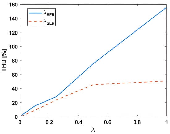
Figure 7.
Switching losses—Mode IV with Balanced Reference Currents.
4. Conclusions
This paper proposed a comprehensive MPC (CMPC) method to reduce losses associated with switching frequency and higher voltage–current switching for a three-phase four-legged inverter (TP4LI). The proposed CMPC method is simple yet intuitive and provides (A) decoupled control for the TP4LI to independently minimize losses associated with (1) switching frequency or (2) high voltage–current switching and (B) integrative control of both A(1) and A(2), while (C) keeping the harmonics under the industry standard limits. The proposed CMPC method is based on MPC; therefore, it uses small memory, offers fast computational speed and parameter robustness, requires no carrier/modulating wave generation, and has good performance.
The TP4LI was operated and controlled using the proposed CMPC-based controller in four different modes: standard MPC (Mode I), switching frequency reduction (Mode II), switching loss reduction (Mode III), and switching frequency plus switching loss reduction (Mode IV) for balanced reference current tracking. Additionally, Mode I (standard MPC) was simulated for unbalanced reference current tracking and unbalanced loads. The results showed that (1) balanced and unbalanced reference currents were successfully tracked for balanced and unbalanced loads; (2) switching frequency losses were reduced in Mode II; (3) switching losses associated with higher voltage–current switch flipping were reduced in Mode III; and (4) both switching frequency and high current/voltage switching losses were reduced in Mode IV.
The simulation results showed that (1) balanced and unbalanced reference currents were successfully tracked for balanced and unbalanced loads; (2) switching frequency losses were reduced in Mode II; (3) losses associated with higher voltage/current switching were reduced in Mode III; and (4) both switching frequency and high current/voltage switching losses were reduced in Mode IV. The proposed controller enables decoupled control in terms of switching frequency or high voltage–current; however, Mode IV has superior performance both in terms of reduction in switching and losses. The THD values for currents were observed to be below the industry standard limits during all four modes of operation.
The authors see the proposed CMPC’s suitability for inverter control in all DC–AC conversion applications, especially in the ever-rising renewable energy sector, such as PV and wind. The authors plan to conduct experimental work to further this work in the future, especially in comparison with the sine PWM and space-vector PWM techniques. Additionally, a smaller-scale experimental setup in a laboratory with a PV module (on the roof), a charge controller, a battery, and an inverter controlled by the CMPC connected to a grid is also in the planning to further this work.
Author Contributions
Conceptualization, I.M.S.; Methodology, I.M.S.; Validation, M.M.F. and M.N.A.; Formal analysis, I.M.S.; Investigation, M.M.F. and M.N.A.; Data curation, Y.M.; Writing—original draft, I.M.S.; Writing—review & editing, Y.M. and M.N.A.; Supervision, I.M.S.; Funding acquisition, None. All authors have read and agreed to the published version of the manuscript.
Funding
This research received no external funding.
Data Availability Statement
No new data were created or analyzed in this study. Data sharing is not applicable to this article.
Conflicts of Interest
The authors declare no conflict of interest.
References
- The World Wind Energy Association “World Wind Energy Report 2009”. Available online: http://www.wwindea.org/home/images/stories/worldwindenergyreport2009_s.pdf (accessed on 5 July 2016).
- The National Renewable Energy Lab Report “2012 Renewable Energy Data Book”. Available online: http://www.nrel.gov/docs/fy14osti/60197.pdf (accessed on 3 June 2016).
- Xue, Y.; Chang, L.; Kjær, S.B.; Bordonau, J.; Shimizu, T. Topologies of Single-Phase Inverters for Small Distributed Power Generators: An Overview. IEEE Trans. Power Electron. 2004, 19, 1305–1314. [Google Scholar] [CrossRef]
- Kjaer, S.B.; Pedersen, J.K.; Blaabjerg, F. A Review of Single-Phase Grid-Connected Inverters for Photovoltaic Modules. IEEE Trans. Ind. Appl. 2005, 41, 1292–1306. [Google Scholar] [CrossRef]
- Mechouma, R.; Azoui, B.; Chaabane, M. Three-phase grid connected inverter for photovoltaic systems, a review. In Proceedings of the International Conference on Renewable Energies and Vehicular Technology, Nabeul, Tunisia, 26–28 March 2012. [Google Scholar]
- Ozkan, Z.; Hava, A.M. Three-phase inverter topologies for grid-connected photovoltaic systems. In Proceedings of the 2014 International Power Electronics Conference, Hiroshima, Japan, 18–21 May 2014. [Google Scholar]
- Zhou, K.; Low, K.; Wang, D.; Luo, F.; Zhang, B.; Wang, Y. Zero-phase odd-harmonic repetitive controller for a single-phase PWM inverter. IEEE Trans. Power Electron. 2006, 21, 193–201. [Google Scholar] [CrossRef]
- Zhang, K.; Kang, Y.; Xiong, J.; Chen, J. Direct repetitive control of SPWM inverter for UPS purpose. IEEE Trans. Power Electron. 2003, 18, 784–792. [Google Scholar] [CrossRef]
- Abrishamifar, A.; Ahmad, A.A.; Mohamadian, M. Fixed switching frequency sliding mode control for single-phase unipolar inverters. IEEE Trans. Power Electron. 2012, 27, 2507–2514. [Google Scholar] [CrossRef]
- Tai, T.L.; Chen, J.S. UPS inverter design using discrete time sliding mode control scheme. IEEE Trans. Ind. Electron. 2002, 49, 67–75. [Google Scholar]
- Fujii, T.; Yokoyama, T. FPGA based deadbeat control with disturbance compensator for single-phase PWM inverter. In Proceedings of the IEEE Power Electronics Specialists Conference, Jeju, Republic of Korea, 18–22 June 2006. [Google Scholar]
- Mattavelli, P. An improved deadbeat control for UPS using disturbance observers. IEEE Trans. Ind. Electron. 2005, 52, 206–212. [Google Scholar] [CrossRef]
- Monfared, M.; Golestan, S.; Guerrero, J.M. Analysis, Design, and Experimental Verification of a Synchronous Reference Frame Voltage Control for Single-Phase Inverters. IEEE Trans. Ind. Electron. 2014, 61, 258–269. [Google Scholar] [CrossRef]
- Oh, W.; Han, S.; Choi, S.; Moon, G. Three Phase Three-Level PWM Switched Voltage Source Inverter with Zero Neutral Point Potential. IEEE Trans. Power Electron. 2006, 21, 1320–1327. [Google Scholar] [CrossRef]
- Kaku, S.; Hashimoto, S.; Yoshida, K. PWM sinusoidal inverter with modulation switching and carrier frequency modulation. In Proceedings of the 1998 International Conference on Power Electronic Drives and Energy Systems for Industrial Growth, Perth, WA, Australia, 1–3 December 1998. [Google Scholar]
- Yuan, D.; Xu, G.; Hu, B.; Xiang, A.; Kong, J. Research on a novel SVPWM for three-phase VSI. In Proceedings of the IEEE Vehicle Power and Propulsion Conference, Harbin, China, 3–5 September 2008. [Google Scholar]
- Garcia, R.C.; Pinto, J.O.P. A New Simplified SVPWM Algorithm Based on Modified Carrier Signal. Rev. Controle Autom. 2011, 22, 545–557. [Google Scholar] [CrossRef]
- Zhang, W.; Yu, Y. Comparison of Three SVPWM Strategies. J. Electron. Sci. Technol. China 2007, 5, 283–287. [Google Scholar]
- Kim, J.-H.; Sul, S.-K. A carrier-based PWM method for three phase four-leg voltage source converters. IEEE Trans. Power Electron. 2004, 19, 66–75. [Google Scholar]
- Rivera, M.; Rodriguez, J.; Yaramasu, V.; Wu, B. A Simple Current Control Strategy for Two-Level Four-Leg Inverters: The Model Predictive Approach. In Proceedings of the 4th International Conference on Power Engineering, Energy and Electrical Drives, Istanbul, Turkey, 13–17 May 2013. [Google Scholar]
- Yaramasu, V.; Rivera, M.; Wu, B.; Rodriguez, J. Model predictive current control of two-level four-leg inverters-part i: Concept, algorithm, and simulation analysis. IEEE Trans. Power Electron. 2013, 28, 459–3468. [Google Scholar] [CrossRef]
- Calle-Prado, A.; Alepuz, S.; Bordonau, J.; Nicolas-Apruzzese, J.; Cortes, P.; Rodriguez, J. Model predictive current control of grid-connected neutral-point-clamped converters to meet low-voltage ride-through requirements. IEEE Trans. Ind. Electron. 2015, 62, 1503–1514. [Google Scholar] [CrossRef]
- Yaramasu, V.; Wu, B.; Alepuz, S.; Kouro, S. Predictive control for low-voltage ride-through enhancement of three-level-boost and npc converter-based pmsg wind turbine. IEEE Trans. Ind. Electron. 2014, 61, 6832–6843. [Google Scholar] [CrossRef]
- Correa, P.; Rodriguez, J.; Lizama, I.; Andler, D. A predictive control scheme for current-source rectifiers. In Proceedings of the 2008 13th International Power Electronics and Motion Control Conference, Poznan, Poland, 1–3 September 2008. [Google Scholar]
- Rivera, M.; Rodriguez, J.; Wu, B.; Espinoza, J.; Rojas, C. Current control for an indirect matrix converter with filter resonance mitigation. IEEE Trans. Ind. Electron. 2012, 59, 71–79. [Google Scholar] [CrossRef]
- Correa, P.; Pacas, M.; Rodriguez, J. Predictive torque control for inverter-fed induction machines. IEEE Trans. Ind. Electron. 2007, 54, 1073–1079. [Google Scholar] [CrossRef]
- Xie, L.; Ilie, M.D. Model Predictive Dispatch in Electric Energy Systems with Intermittent Resources. In Proceedings of the 2008 IEEE International Conference on Systems, Man and Cybernetics, Singapore, 12–15 October 2008. [Google Scholar]
- Perez, E.; Beltran, H.; Aparicio, N.; Rodriquez, P. Predictive Power Control for PV Plants with Energy Storage. IEEE Trans. Sustain. Energy 2013, 4, 482–490. [Google Scholar] [CrossRef]
- Hu, J.; Zhu, J.; Guerrero, J.M. Model predictive control in next microgrid control architectures. In Proceedings of the 17th International Conference on Electrical Machines and Systems, Hangzhou, China, 22–25 October 2014. [Google Scholar]
- Morari, M.; Lee, J.H. Model predictive control: Past, present and future. Comput. Chem. Eng. 1999, 23, 667–682. [Google Scholar] [CrossRef]
- Rodríguez, J.; Pontt, C.S.; Correa, P.; Lezana, P.; Cortés, P.; Ammann, U. Predictive current control of a voltage source inverter. IEEE Trans. Ind. Electron. 2007, 54, 495–503. [Google Scholar] [CrossRef]
- Vazquez, S.; Leon, J.I.; Franquelo, L.G.; Rodriguez, J.; Young, H.A.; Marquez, B.; Zachetta, P. Model Predictive Control: A Review of Its Applications in Power Electronics. Ind. Electron. Mag. 2014, 8, 16–31. [Google Scholar] [CrossRef]
- Syed, I.M.; Raahemifar, K. Space Vector PWM and Model Predictive Control for Voltage Source Inverter Control. Int. J. Electr. Comput. Electron. Commun. Eng. 2014, 8, 1562–1568. [Google Scholar]
- Ayad, A.F.; Kennel, R.M. Model Predictive Controller for Grid-Connected Photovoltaic based on Quasi-Z-Source Inverter. In Proceedings of the IEEE International Symposium on Sensor-less Control for Electrical Drives and Predictive Control of Electrical Drives and Power Electronics, Munich, Germany, 17–19 October 2013. [Google Scholar]
- Syed, I.M.; Raahemifar, K. Model Predictive Control of Single Phase Inverter for PV System. Int. J. Electr. Comput. Electron. Commun. Eng. 2014, 8, 1618–1623. [Google Scholar]
- Mosa, M.; Abu-Rub, H.; Ahmed, M.E.; Kouzoul, A.; Rodríguez, J. Control of Single Phase Grid Connected Multilevel Inverter Using Model Predictive Control. In Proceedings of the 4th International Conference on Power Engineering, Energy and Electrical Drives, Istanbul, Turkey, 13–17 May 2013. [Google Scholar]
- Hu, J.; Cheng, K.W.E. Predictive Control of Power Electronics Converters in Renewable Energy Systems. Energies 2017, 10, 515. [Google Scholar] [CrossRef]
- Moghadasi, A.; Sargolzaie, A.; Khalilnejad, A.; Moghaddami, M.; Sarwat, A. Model Predictive Power Control Approach for Three-Phase Single-Stage Grid-Tied PV Module-Integrated Converter. In Proceedings of the IEEE Industrial Application Society Annual Meeting, Portland, OR, USA, 2–6 October 2016. [Google Scholar]
- Hu, J.; Zhu, J.; Dorrell, D.G. Model-Predictive Control of Grid-Connected Inverters for PV Systems with Flexible Power Regulation and Switching Frequency Reduction. In Proceedings of the IEEE Conference on Energy Conversion Congress and Exposition, Denver, CO, USA, 15–19 September 2013. [Google Scholar]
- Rodriguez, J.; Wu, B.; Revera, M.; Rojas, C.; Yaramasu, V.; Wilson, A. Predictive Current Control of Three-Phase Two-Level Four-Leg Inverter. In Proceedings of the 14th International Power Electronics and Motion Control Conference, Ohrid, Macedonia, 6–8 September 2010. [Google Scholar]
- Yaramasu, V.; Wu, B. Predictive Control of a Three-Level Boost Converter and an NPC Inverter for High-Power PMSG-Based Medium Voltage Wind Energy Conversion Systems. IEEE Trans. Power 2014, 29, 5308–5322. [Google Scholar] [CrossRef]
- Kim, S.; Park, S.; Kwak, S. Simplified Model Predictive Control Method for Three-Phase Four-Leg Voltage Source Inverters. J. Power Electron. 2016, 16, 2231–2242. [Google Scholar] [CrossRef]
- Omar, R.G.; Thejel, R.H. Finite Control Set Model Predictive Current Control MPC Based on Cost Function Optimization, with Current Limit Constraints for Four-Leg VSI. Iraqi J. Electr. Electron. Eng. 2016, 12, 43–53. [Google Scholar] [CrossRef]
- 60kW Inverter Model—SG 60KU. Available online: http://en.sungrowpower.com/ (accessed on 17 October 2017).
- 25 kW Inverter Model—Conext CL-25 NA. Available online: https://solar.schneider-electric.com/product/conext-cl-na-solar-inverter/ (accessed on 28 December 2017).
- STGW30NC120HD N-Channel 1200V-30A-O-247 IGBT Datasheet STMicroelectronics group of companies. Available online: https://www.st.com/resource/en/datasheet/stgw30nc120hd.pdf (accessed on 8 March 2023).
- Ivakhno, V.; Zamaruiev, V.; Ilina, O. Estimation of Semiconductor Switching Losses under Hard Switching using MATLAB/Simulink Subsystem. Electr. Control Commun. Eng. 2013, 2, 20–26. [Google Scholar] [CrossRef]
- Rajapakse, A.D.; Wilson, P.L. Approximate Loss Formulae for Estimation of IGBT Switching Losses through EMTP-type Simulations. In Proceedings of the International Conference on Power Systems Transients, Montreal, QC, Canada, 19–23 June 2005. [Google Scholar]
Disclaimer/Publisher’s Note: The statements, opinions and data contained in all publications are solely those of the individual author(s) and contributor(s) and not of MDPI and/or the editor(s). MDPI and/or the editor(s) disclaim responsibility for any injury to people or property resulting from any ideas, methods, instructions or products referred to in the content. |
© 2023 by the authors. Licensee MDPI, Basel, Switzerland. This article is an open access article distributed under the terms and conditions of the Creative Commons Attribution (CC BY) license (https://creativecommons.org/licenses/by/4.0/).