1. Introduction
Belt conveyors are devices transporting various types of materials with granulation adapted to width
bt. The belt is an element that moves the material at a certain speed [
1,
2]. The efficiency of the conveyor results from the active cross-sectional area of the material on the belt
Fp (trough) and its speed
vt. The characteristic parameters of the belt conveyor are therefore its length
bt and speed
vt [
3,
4,
5]. These parameters, together with the type of transported material and the inclination of the conveyor
αp, determine the size of installed power
Np [
6,
7]. A typical belt conveyor with an upper conveyor belt consists of a return pulley, a supporting structure, usually in the form of a grid with idlers, and a drive with an electric motor or, less frequently, a hydraulic motor and a mechanical transmission. The movement of the belt, powered by the drive, at a certain speed
vt on idlers built on supports (trestles) from the return pulley to the drive, and causing the material to be transferred with the required efficiency, is a working movement. In contrast, the movement of the belt from the drive to the return pulley is a return (idle) movement; in this case, the belt also moves on idlers, but only single ones. As mentioned before, belt conveyors are devices that transport various types of materials in a continuous way. Therefore, they are mostly applied wherever constant feeding of material with a certain efficiency is required [
3,
4].
The above information applies to all belt conveyors with lengths ranging from several metres to even several kilometres, and belt widths from several centimetres to more than two meters [
8,
9]. This group of conveyors includes short belt conveyors with a length of up to 40 m and a belt width reaching up to 1 m, often referred to as belt feeders [
10,
11].
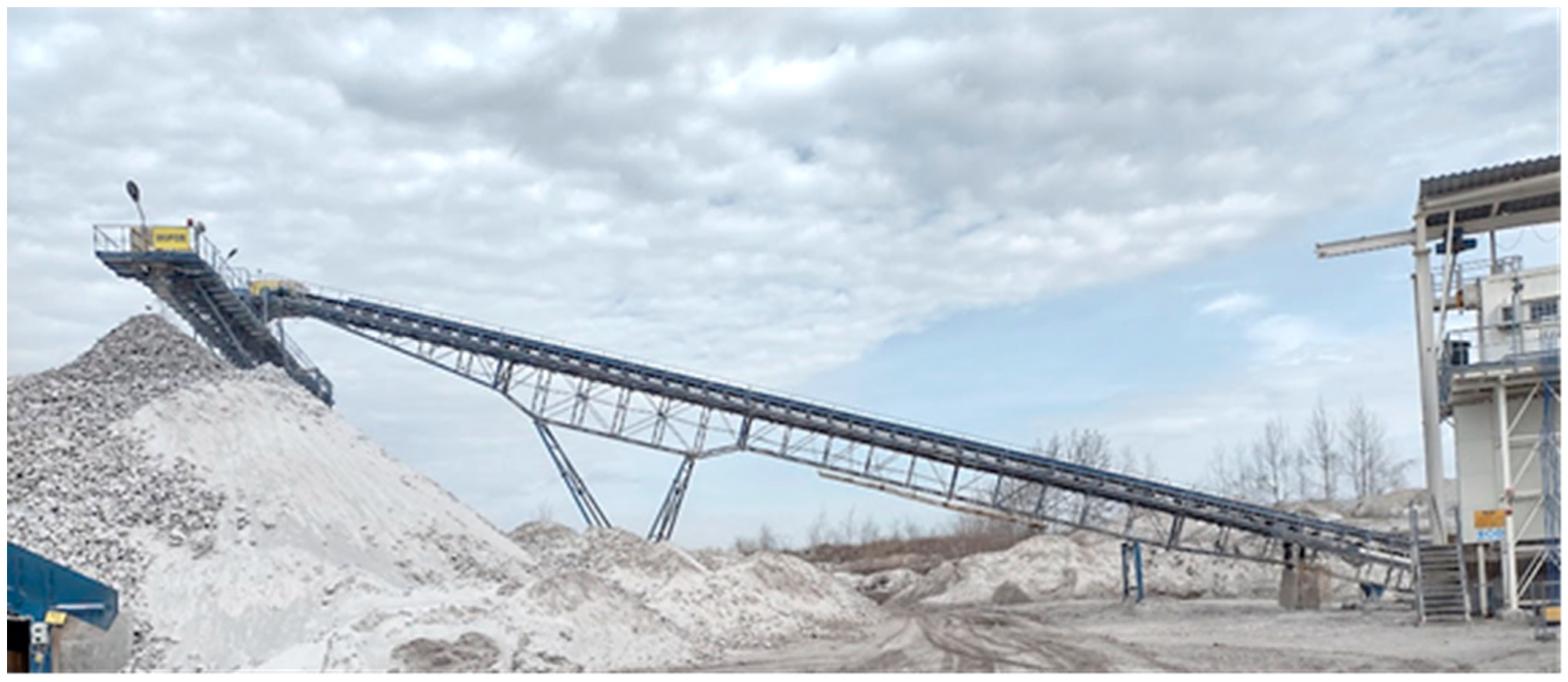
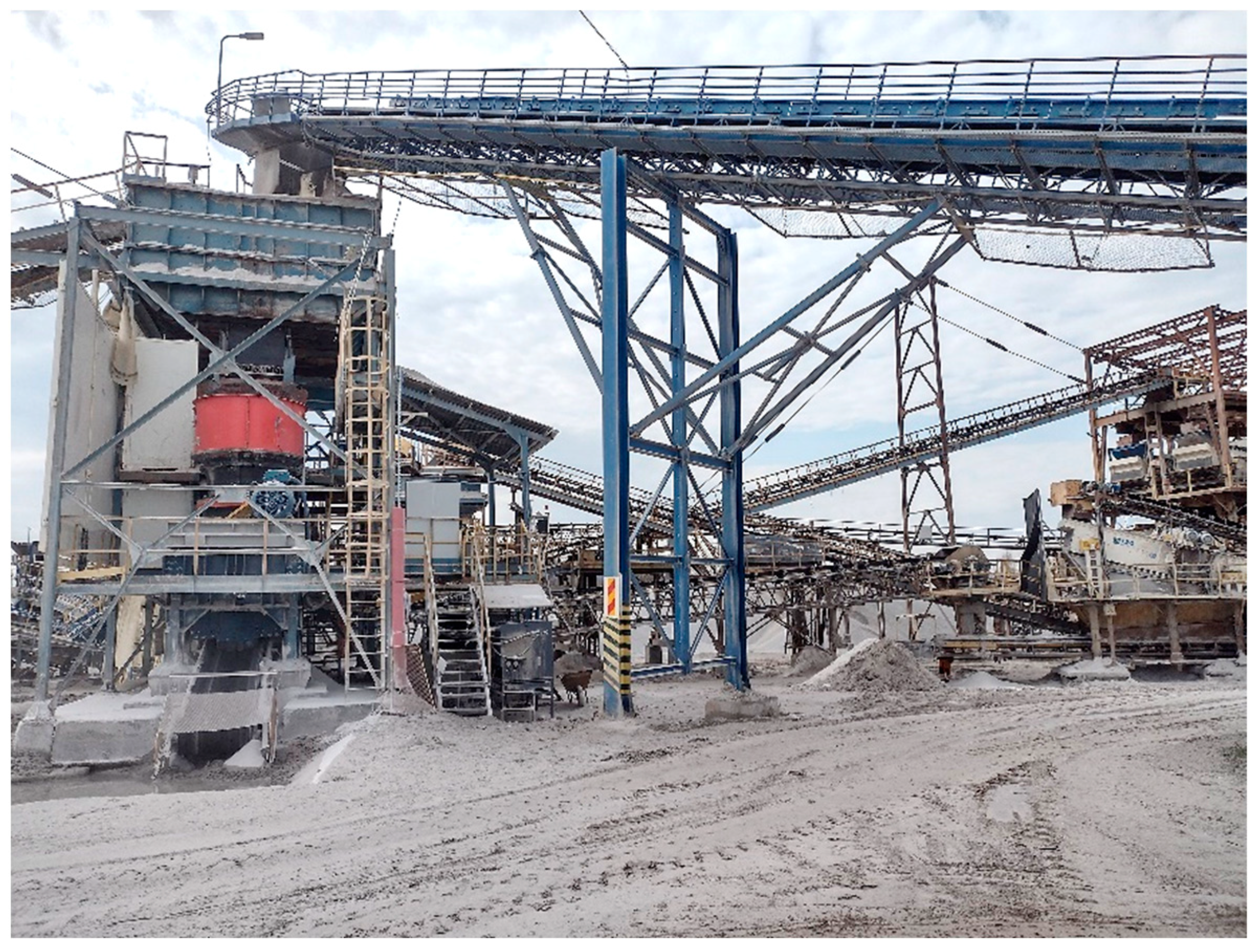
Due to their broad scope of work, belt feeders are eagerly chosen by investors in various industries. They are commonly used in reloading and transporting works, warehouses, landfills, construction sites, plants processing and exploiting materials and mineral resources (
Figure 1), and for transporting excavated material and overlayers in the mining industry. These devices guarantee the stable and safe transport of materials. The entire process is convenient and quick, which brings significant benefits (saving time and money). Users are sure that the investment in high-class feeders will pay off quickly, and the profits will be felt for years. The use of belt feeders means easy assembly, disassembly, and transport because the structures are modular—assembled from ready-made elements. It allows the modernisation of production or distribution and adapting it to current standards. A large selection of parts and accessories allows users to modify the structure as needed. Additionally, the operation of belt feeders is quite quiet.
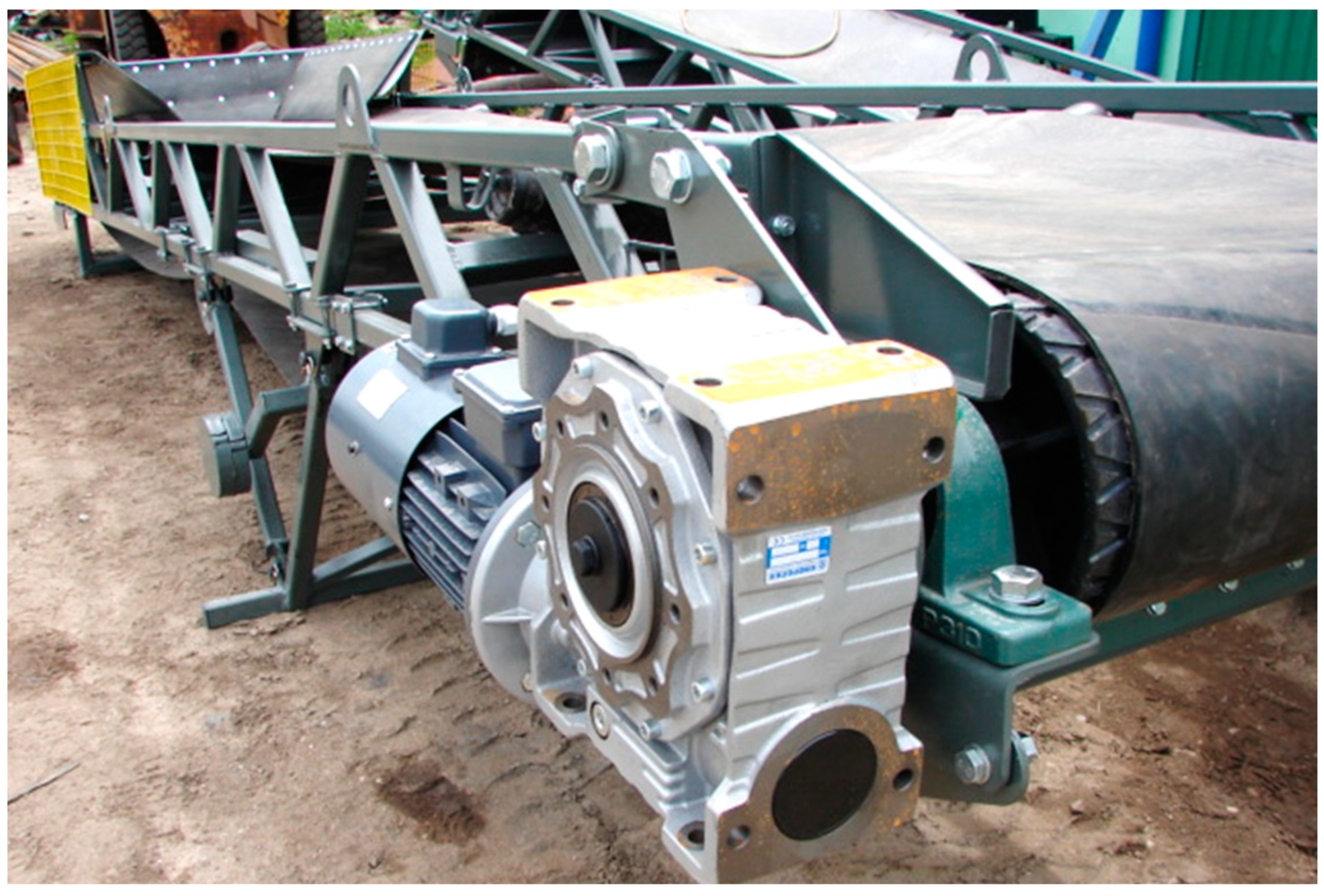
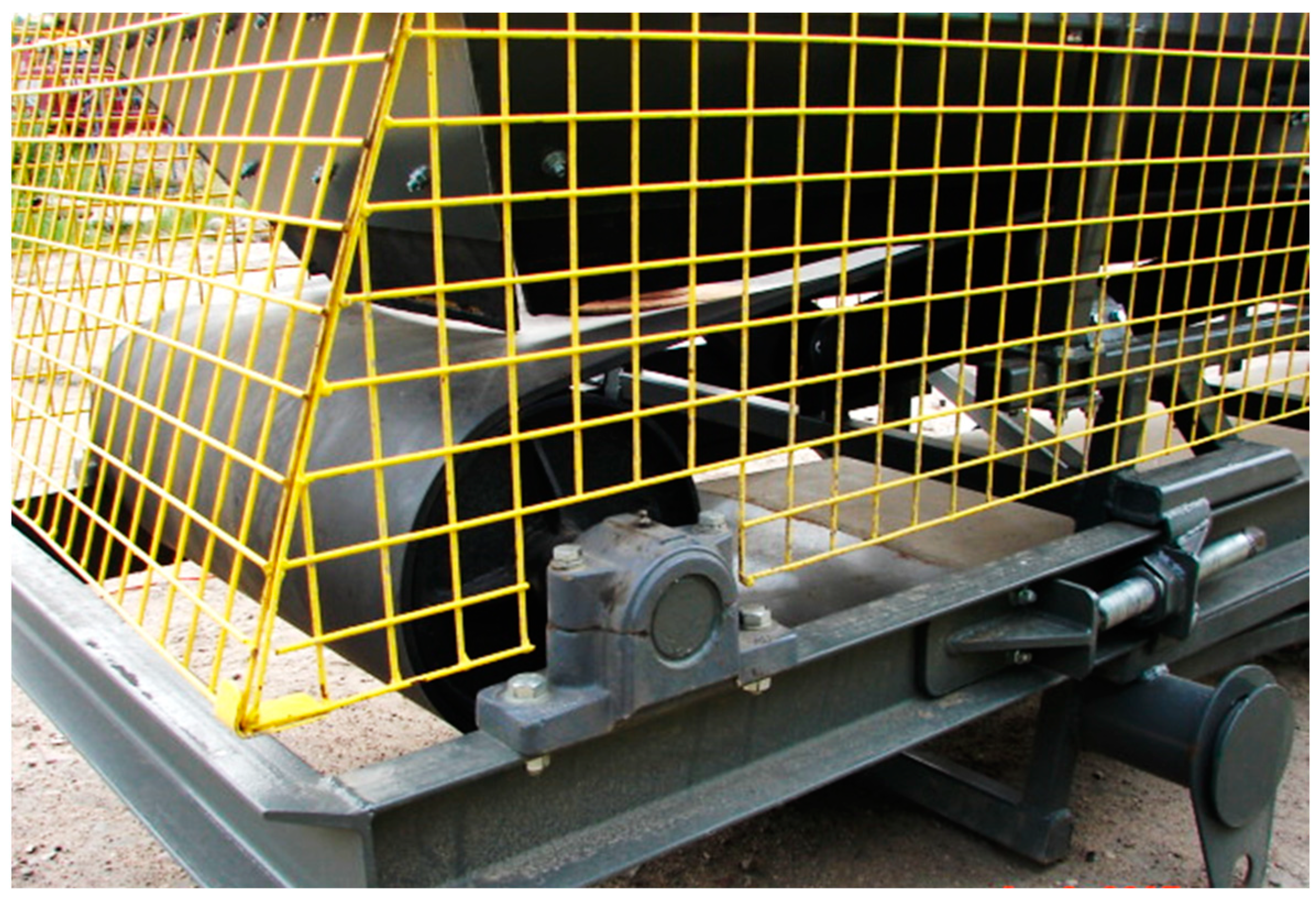
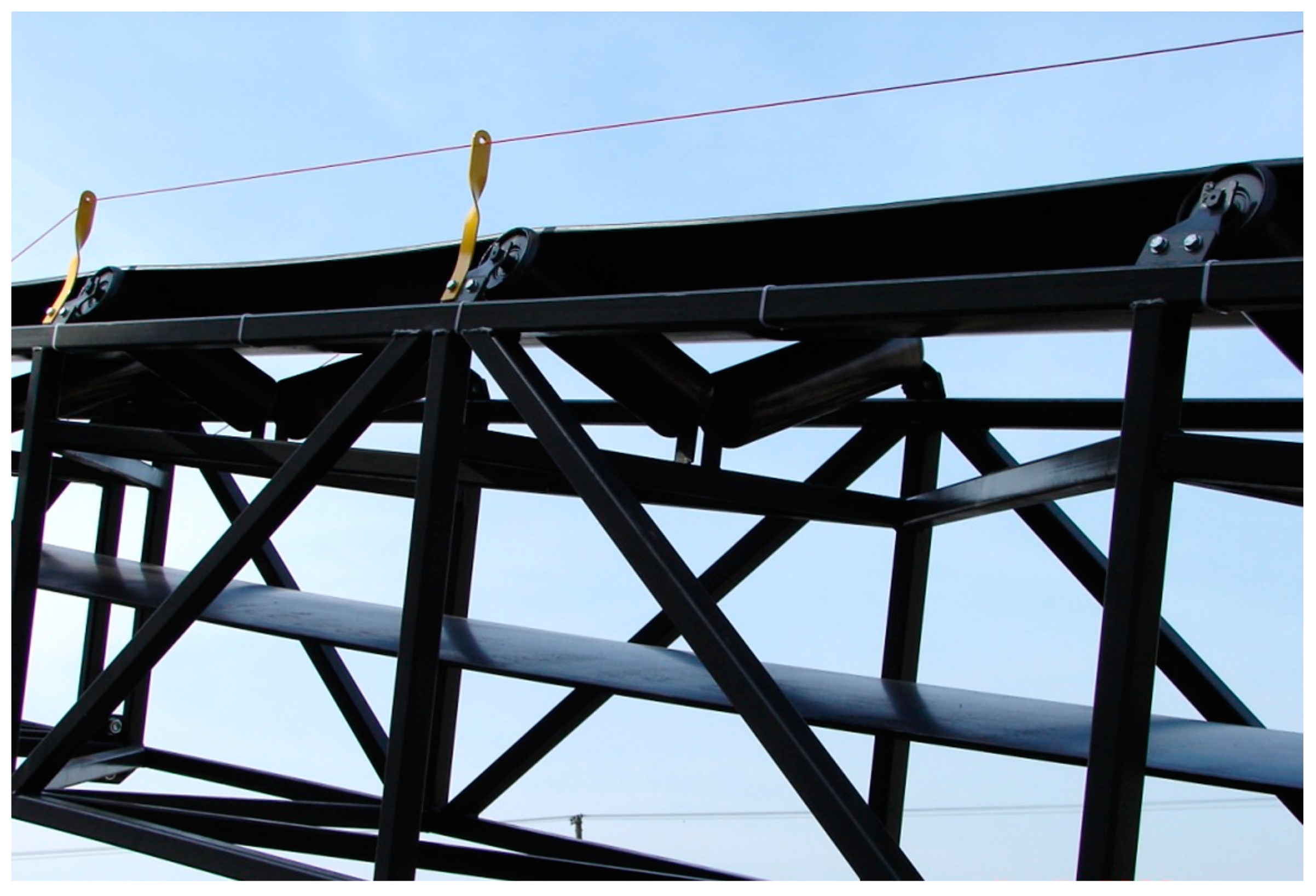
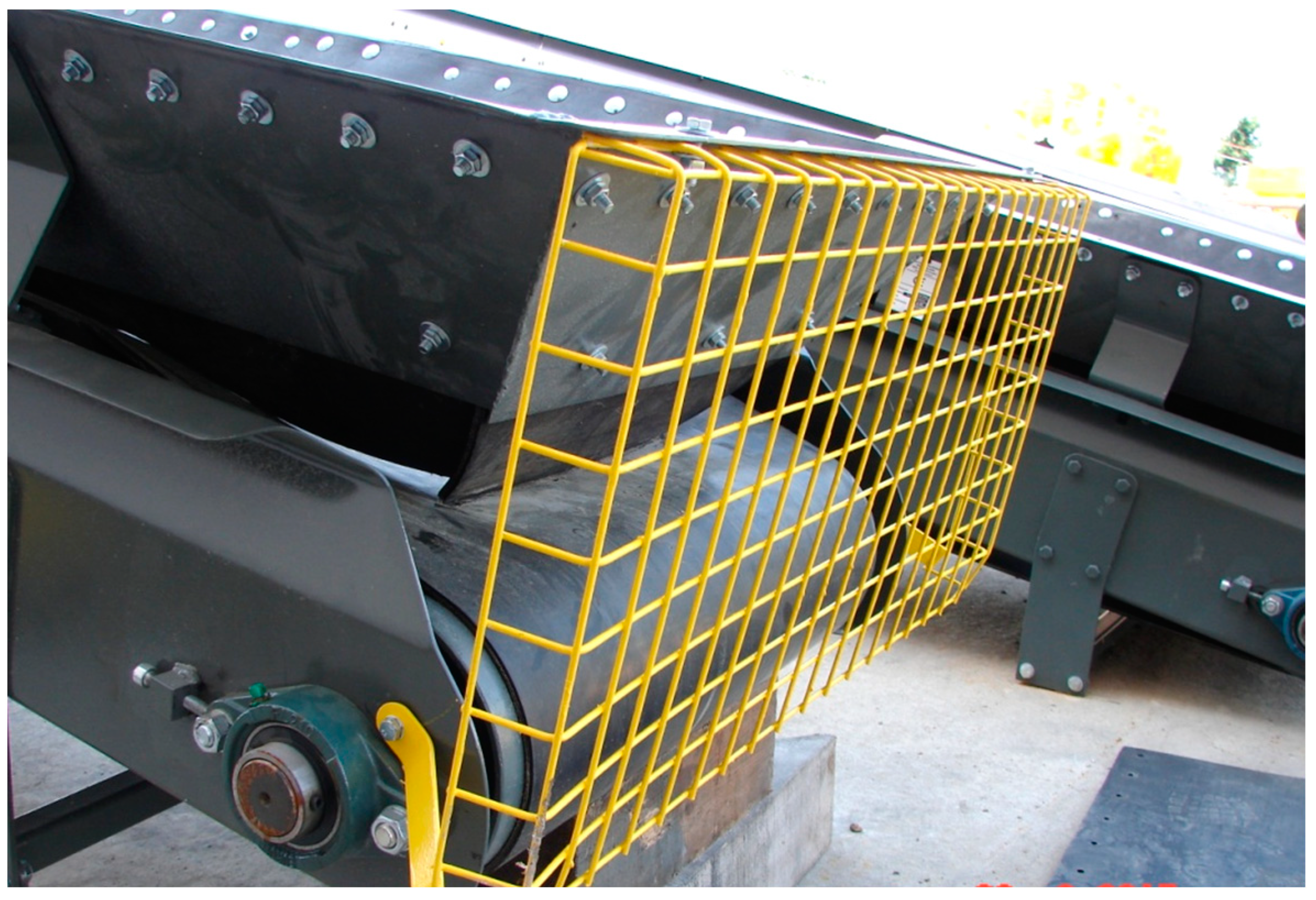
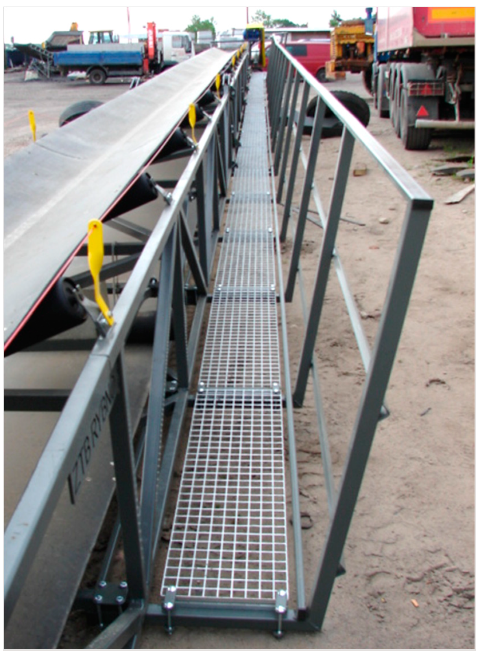
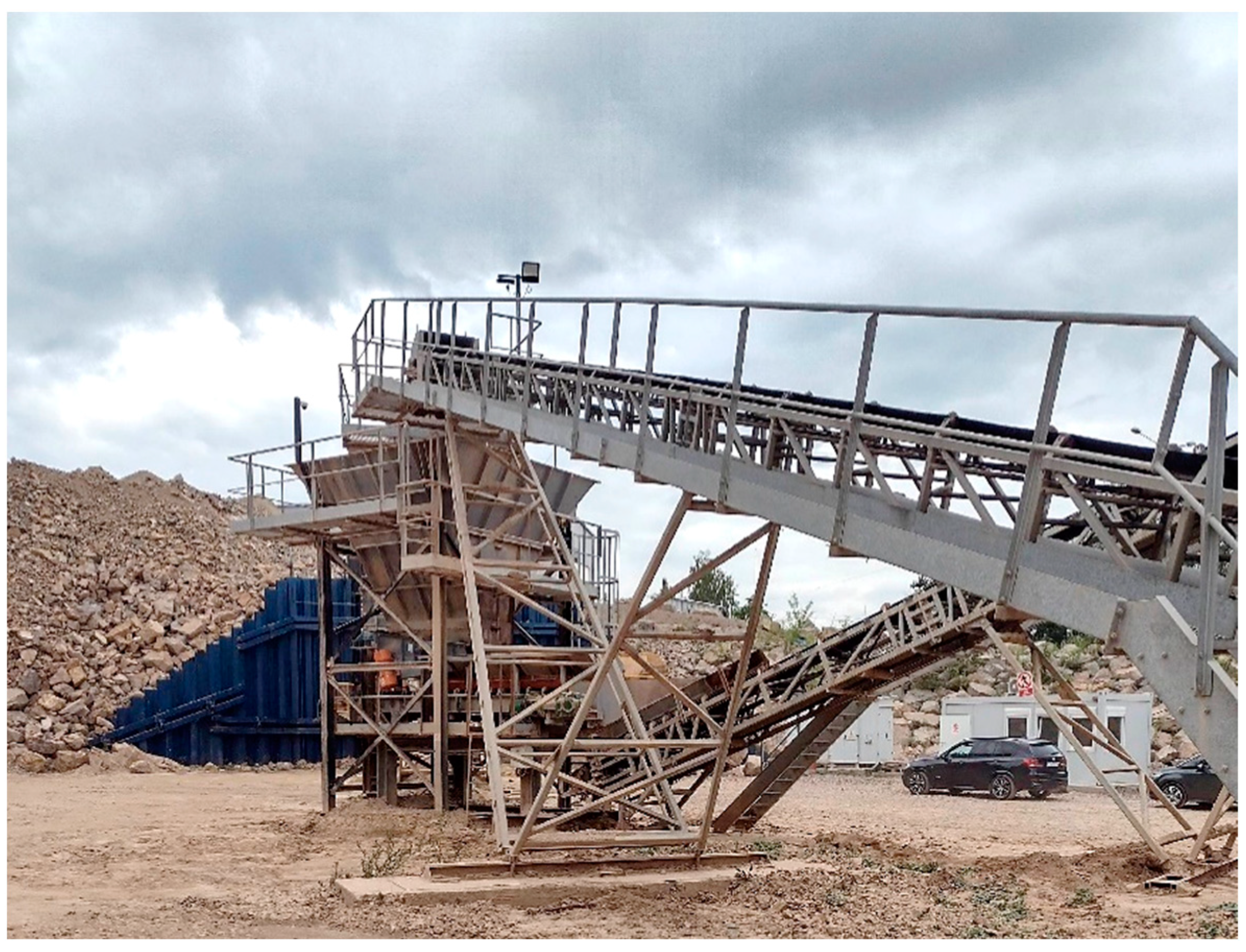
For the mineral resources industry, belt feeders are, among others, used in opencast rock mining for transporting the crushed mineral. They are usually included in the process line, moving the mineral from one loading point (feeder, tank, screen, or crusher) to another discharge point (other means of transport, warehouse, or heap). Typically, the above-mentioned feeders consist of a drive (
Figure 2), a return pulley (
Figure 3) and a route (
Figure 4) with idlers and a belt. Such a feeder moves the material lying on the belt at angle
αtp, usually upwards. The maximum value of this angle results from the frictional coupling between the transported material and the belt
μtu (
αtp + Δ
αtp ≤ arctg
μtu). It can work horizontally (Δ
αtp = 0°) and on a downward negative slope (Δ
αtp ˂ 0°) or on an upward positive slope (Δ
αtp > 0°) [
3]. Additional equipment utilised with such feeders are a charging hopper (
Figure 5) and a discharge hopper, external and internal scrapers, platforms (
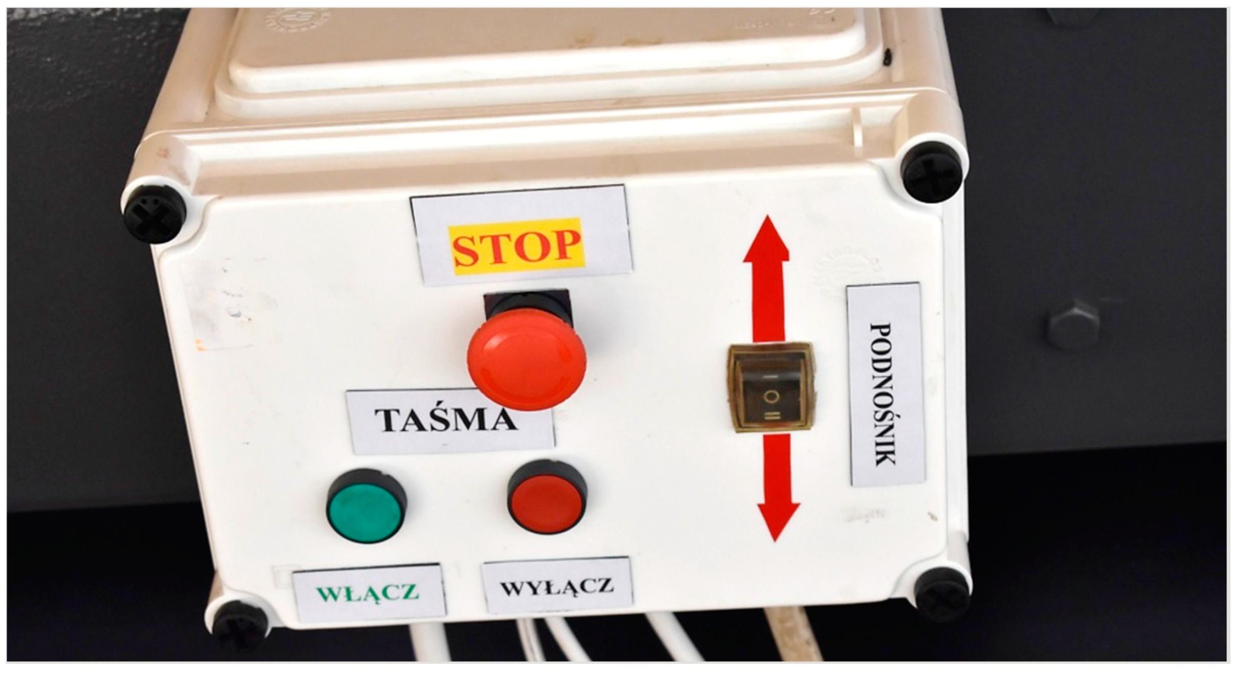
Figure 6), as well as various types of protection related mainly to health and safety regulations and control (
Figure 7) [
12,
13].
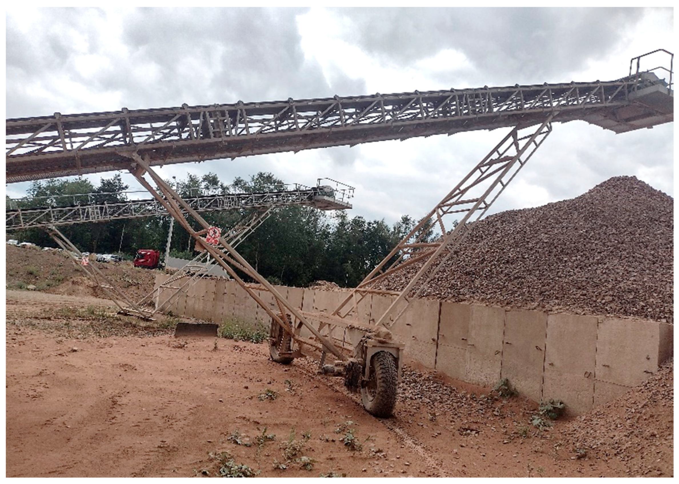
A characteristic feature of these feeders is their installation in the workplace, on stationary or mobile supports. Straight stationary supports (SSSs) are built on previously made foundations (
Figure 8), and their number is dependent on the length of the feeder. The V-type stationary supports (VSSs), equipped with slides (skids), hold the feeder structure at the required angle
αtp, resting on the ground (
Figure 9). If wheels are installed in place of skids, V-type mobile supports (VMS) are used (
Figure 10). Belt feeders with V-type stationary supports are the most common [
1,
2,
3], which poses a big challenge due to the stability of the structure, both during operation and at standstill. This issue requires the testing of the feeder’s stability [
14] at the design stage and subsequent operational tests.
The available literature is rich in issues related to various aspects of belt conveyors. There are a few articles related to belt feeders; among others, Maton [
15] and Bates [
16] tested and calculated the load on such feeders. However, as yet, there is no description of the problem related to the stability of the belt feeder structure and its load. Therefore, an analytical model of a typical belt feeder with V-type supports was developed, and its stability and the forces in the supports were determined. It is worth emphasising that all the parameter values adopted for the calculations were obtained from belt feeder manufacturers and users. These are the actual values with which these feeders work. As a result, an application was developed using computer technology to test the feeder’s stability at the design stage or while making changes.
2. Analytical Model of the Belt Feeder
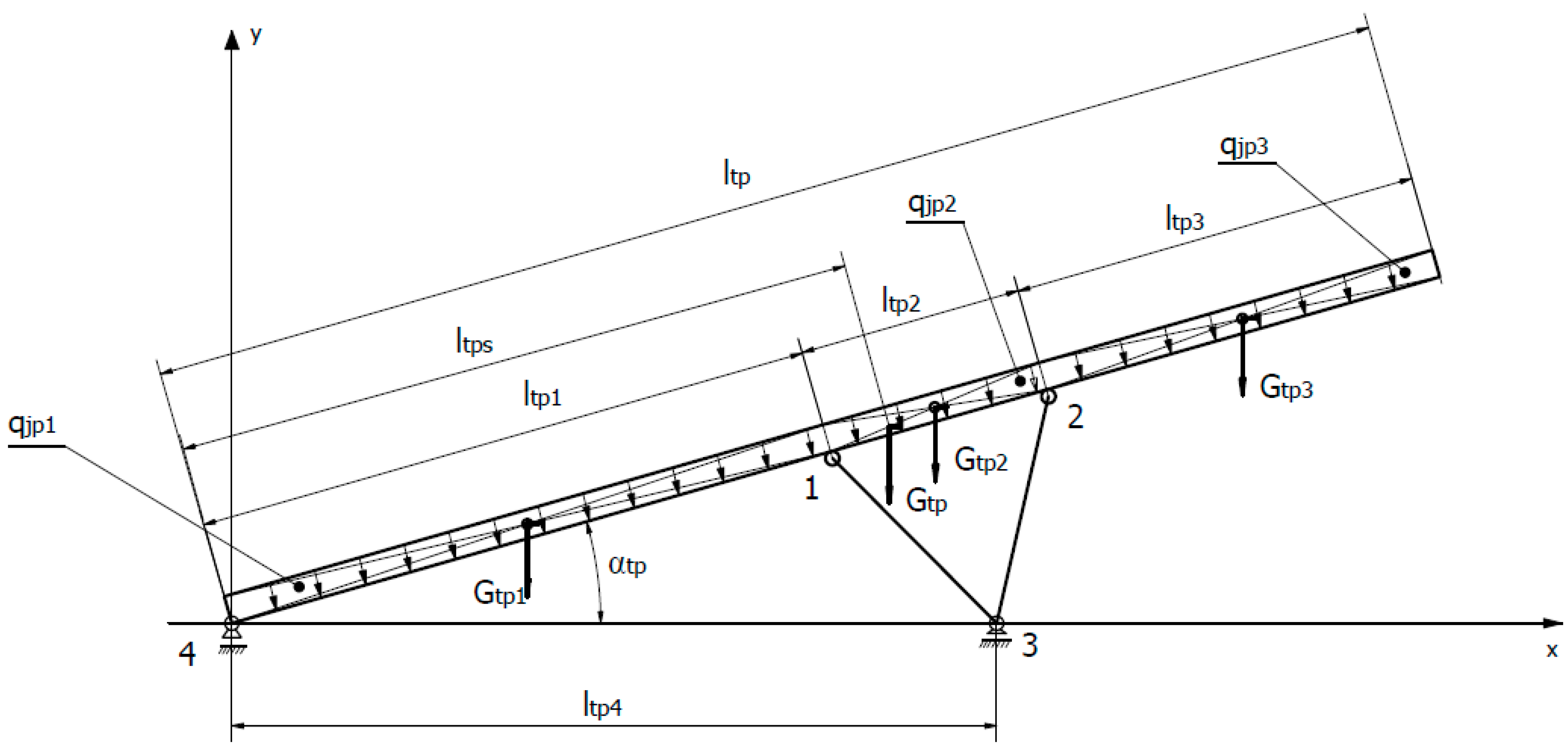
The starting point for developing an analytical model of the VSS and VMS belt feeder in order to assess its stability is the reduction of masses [
17]. This allows the determination of the coordinates of the centre of mass of the feeder’s supporting structure (
Figure 11). The continuous linear load
qjpi,, different for the three parts of the belt feeder (1), was assumed as rectangles with known coordinates of the centre of mass. The first part of the feeder’s supporting structure is the section stretching from the hopper (return pulley) to the first support, the second part is the section between the supports, and the third one stretches from the second support to the discharge (drive). This model does not take into account the weights of the feeding hopper
Gz (drum, belt tension, hopper, and covers) or the discharge
Gw (drum, counterweight drive, and platform). These will be taken into account when determining the forces and moments for the entire feeder.
where:
qtpi—linear continuous load for the i-th section of the feeder;
ltpi—length of the i-th section of the feeder;
n—number of feeder sections under consideration.
Concentrated weights for the three sections of the belt feeder can be determined from dependencies (2), (3), and (4). The total weight of the supporting structure of the belt feeder
Gtp is the sum of three individual weights
Gtp1,
Gtp2, and
Gtp3 (5). Similarly, the total length of the belt feeder
ltp is the sum of its three sections
ltp1,
ltp2, and
ltp3 (6). For the conditions of equilibrium relative to the y-axis, it is possible to determine the resultant moment
MGtp as well as single moments for the three masses
MGtp1,
MGtp2, and
MGtp3, which balance each other (7). The structural dimensions of the feeder’s route and the locations of the concentrated weights
Gtp1,
Gtp2, and
Gtp3 (8), (9), (10), and the resultant mass (11) allow the determination of the coordinate of the centre of mass
ltps of the resultant mass M
Gtp for different (13) or identical continuous linear loads
qtpi (14).
On the basis of Formula (7) as well as (8), (9), and (10), the
MGtp dependence can be expressed (12) as follows:
Based on Formula (11) and Formulas (2)–(5), the coordinate of the centre of mass
lps describes dependence (13) or (14) if (6) is taken into consideration.
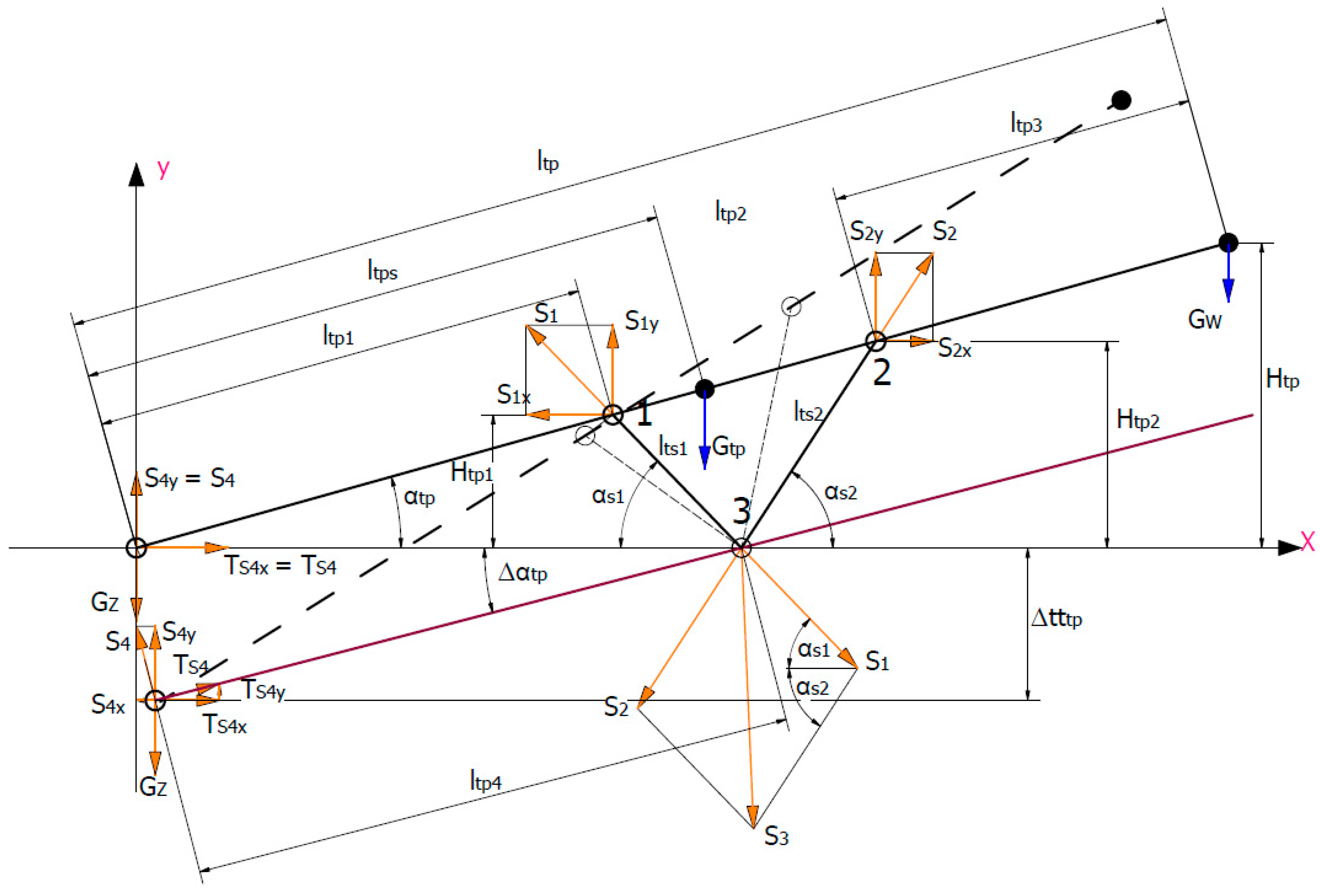
The above dependencies allowed the development of an analytical model of the VSS or VMS belt feeder (
Figure 12), located in a horizontal excavation (Δ
αtp = 0°), inclined upwards (Δ
αtp > 0°) and inclined downwards (Δ
αtp ˂ 0°). The belt feeder, with the load-bearing structure weight
Gtp, the weight of the discharge (drive)
Gw, and the feeding hopper (return pulley)
Gz, is supported at points 3 and 4. The feeder’s return pulley (point 4) exerts pressure on the ground with the force of reaction
S4, whereas reaction
S3 at point 3 comes from two forces
S1 and
S2 in the supports having lengths
lst1 and
lst2. At point 3, friction force
Ts4 will occur. Attaching the supports in points 1 and 2 should ensure the stability of the feeder (permanent equilibrium); i.e., in this case, reaction
S4 must always be positive. This is possible when the moment about pole (point) 3 is zero or positive. By projecting the forces onto the x- and y-axes and determining the moments of these forces relative to point 3, dependencies describing reaction forces
S1,
S2,
S3, and
S4 can be obtained. However, prior to this, it is necessary to establish the relationships between the construction parameters of the feeder, especially with
αtp, Δ
αtp, and
ltp. Height
Htp, to which the feeder can transport the material, is described by dependence (15), whereas heights
Htp1 and
Htp2 can be determined from dependencies (16) and (17). The angles of inclination of support 1
αs1 having length
ltp1 and of support 2
αs2 with length
ltp2 are described by dependencies (18) and (19). The required support length 1
lts1 results from the value of angle
αs1 and height
Htp1 (20). The same is true for support 2, where its length
ltp2 also results from the value of angle
αs1 and height
Htp2 (21).
When the above analytical relationships between the design parameters of the belt feeder are known, it is possible, using the force balance equations (x- and y-axis) and moments (point 3), to obtain the dependencies describing the searched reaction forces
S1,
S2,
S3, and
S4 and to test the stability of the structure. The sum of the projections of forces on the x-axis should be zero (22).
Similarly, when these forces are projected onto the y-axis, their sum should also be zero (29).
For the structure to remain in equilibrium, the sum of the moments relative to point 3 should also be zero (37). As a result of transforming Equation (37) and introducing additional notations (38), (39), (40), (41), (42), and (43), the dependence describing force
S4 (44) was obtained.
By transforming Equation (22) and introducing additional notations (45), (46), and (47), the force
S1 dependence (48) was obtained.
By transforming Equation (29) and introducing additional notations (49), (50), and (51), the force
S2 (52) dependence (52) was obtained.
Reaction
S3 at point 3 is the geometric sum of forces
S1 and
S2 (53).
The obtained analytical dependencies resulting from the adopted model of the belt feeder make it possible to determine the forces that are important for its structure load and stability. This is, of course, particularly important at the stage of creating the model, and designing and preparing documentation, but also when making changes to the feeder structure (modernising). As mentioned in the introduction, one should also remember the adhesion of the excavated material to the belt, expressed by the coefficient of friction
μtu, which corresponds to friction angle
ρtw. Then, the total angle of feeder inclination (
αtp + Δ
αtp) cannot exceed the value of angle
ρtw (54). Of course, changing the angle of the feeder’s inclination also requires checking its stability.
The above-mentioned comments and requirements resulted in the development of an algorithm and a computer application that enable the load of the feeder structure and its stability to be calculated, without the need to use CAD programs.
3. Application for Designing and Analysing the Construction of a Belt Feeder
In order to support the design and analysis of the feeder load, an application in the Matlab environment has been developed. After compilation, it will be an independent application.
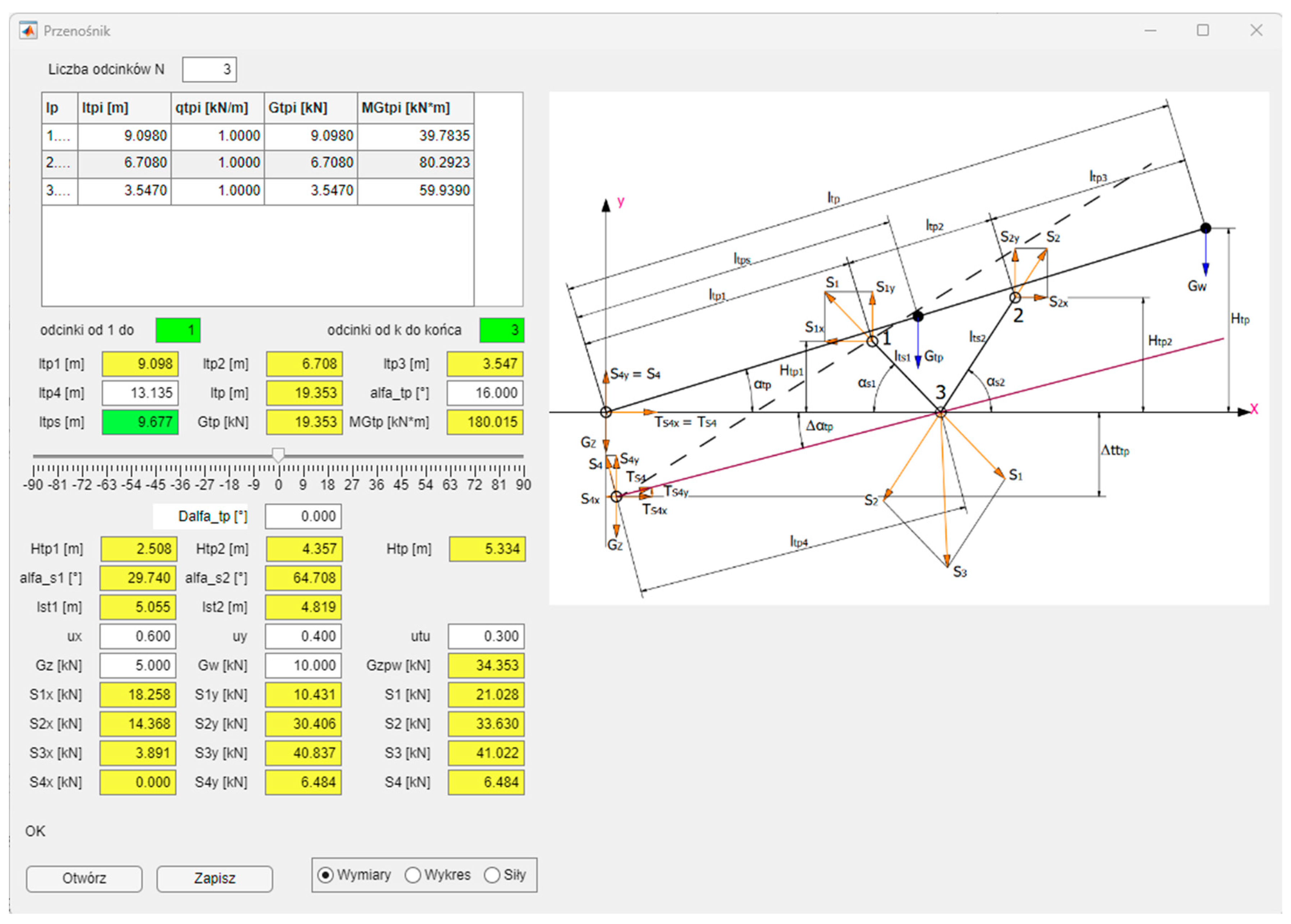
Figure 13 shows the main application window.
In the left part of the application window, one can see the data entered by the user and the results of calculations based on the relationships presented in the previous section. The input data are the lengths and weights of the feeder elements (top right corner of the application), the distance ltp4, the angle of the feeder inclination αtp, the angle of the feeder’s deviation from the base plane (lowering or elevating the starting point of the feeder), orthogonal components of the friction coefficients μx and μy, as well as the forces (of weights) Gz and Gw. All these quantities are entered in the white edit boxes. Yellow and green edit boxes are reserved for calculation results. Each change in the input quantity causes recalculation of all the dependencies. The input data entered in the feeder calculations can be saved in a text file with the “Save” button to enable quick loading of the data with the “Open” button without re-entering the data manually. An important element of the application is the ability to change the value of angle Δαtp, i.e., rotate the feeder around support point 3.
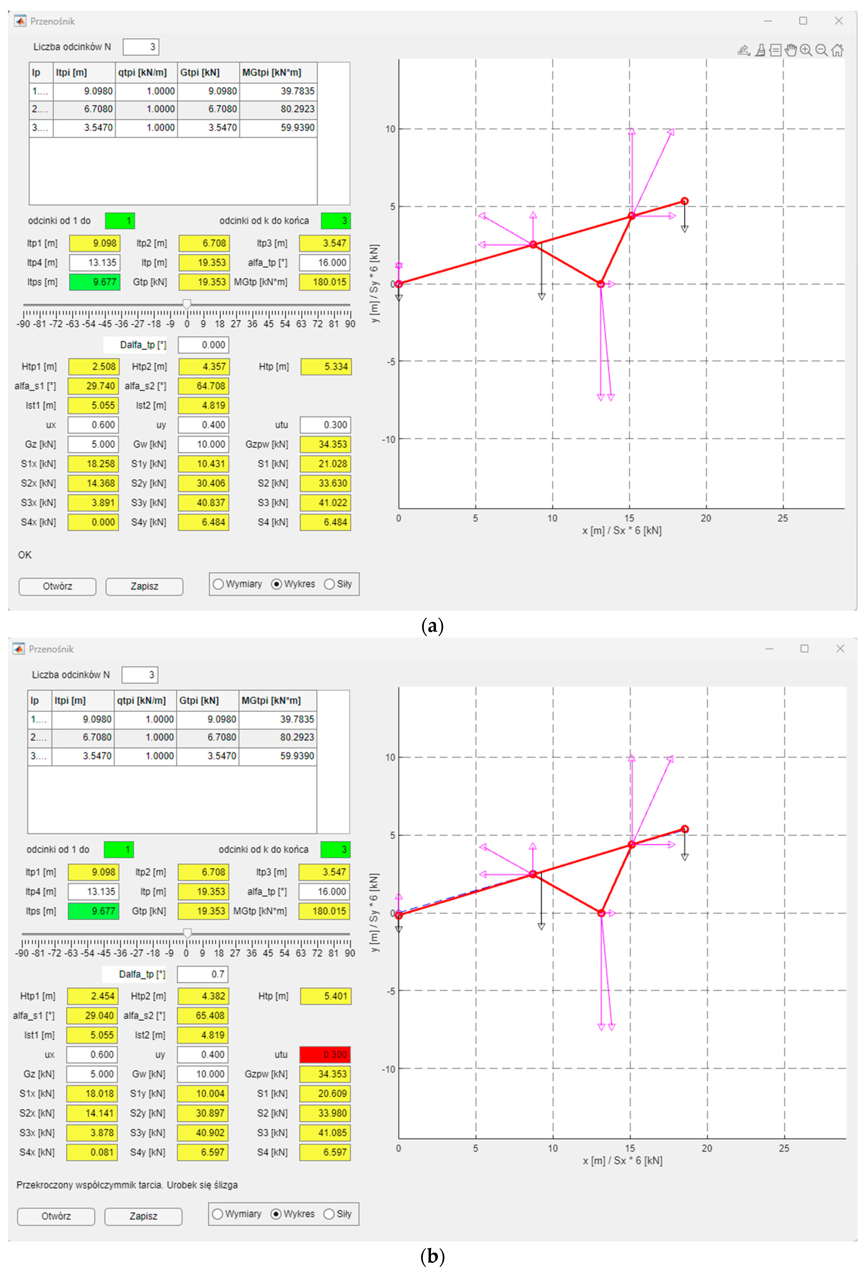
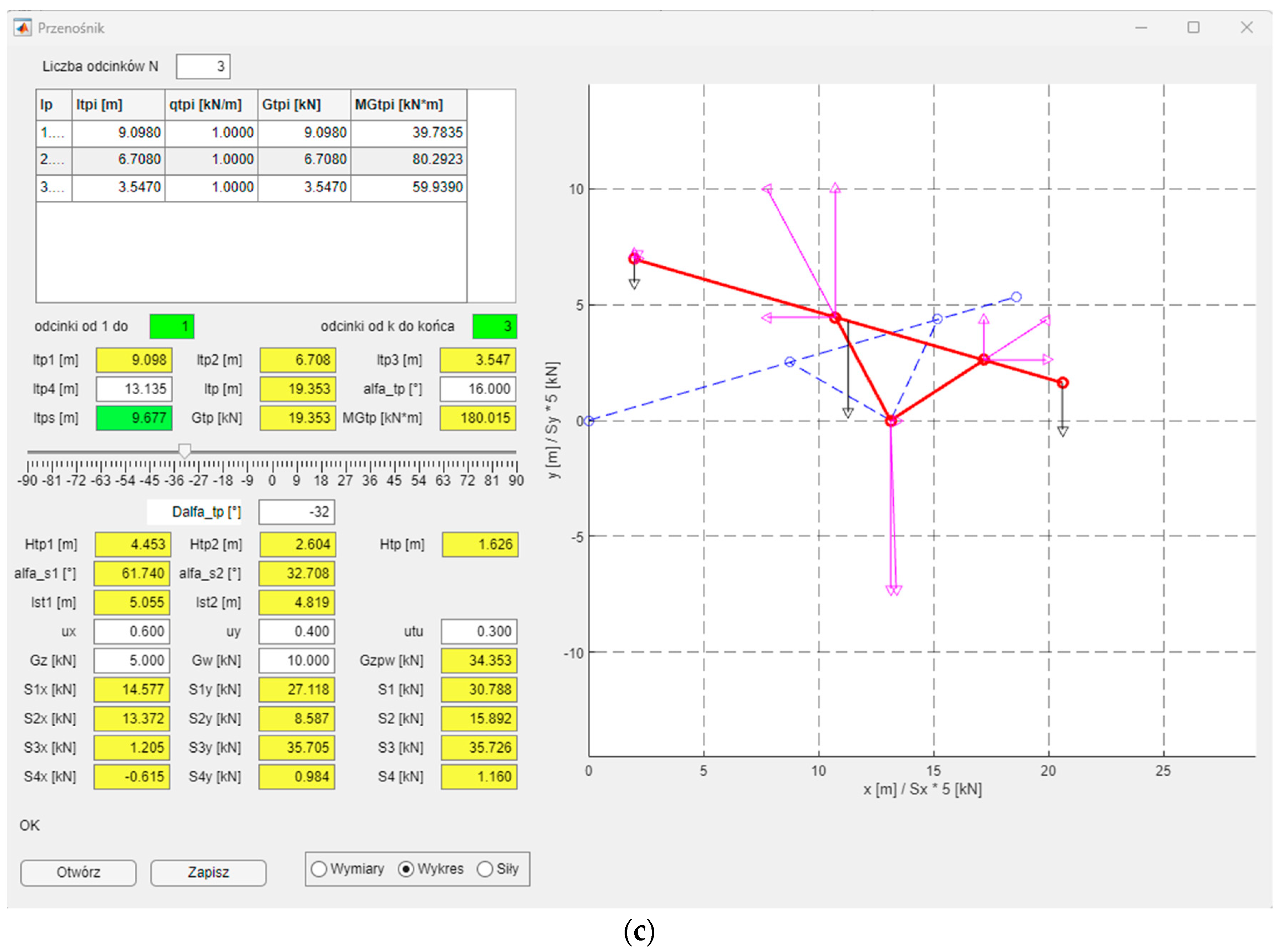
In the lower right part of the application, there is a three-position switch for selecting the drawings located on the right side of the application. Initially, a diagram of the feeder with its marked dimensions (parameters) and the forces acting on it is drawn. This considerably facilitates entering the input data and interpreting the obtained results, as they can be quickly located. The second option “Graph” is a visualisation of the feeder based on the entered and calculated data (
Figure 14). In this option, the designed feeder is drawn in the neutral position (Δ
αtp = 0°) with a blue dashed line, and in the position taking into account the set angle Δ
αtp. In the case of the second option, the acting forces (weights)
Gz,
Gw,
Gzpw (black), as well as forces
S1,
S2,
S3, and
S4 with their orthogonal components are drawn. A change in angle Δ
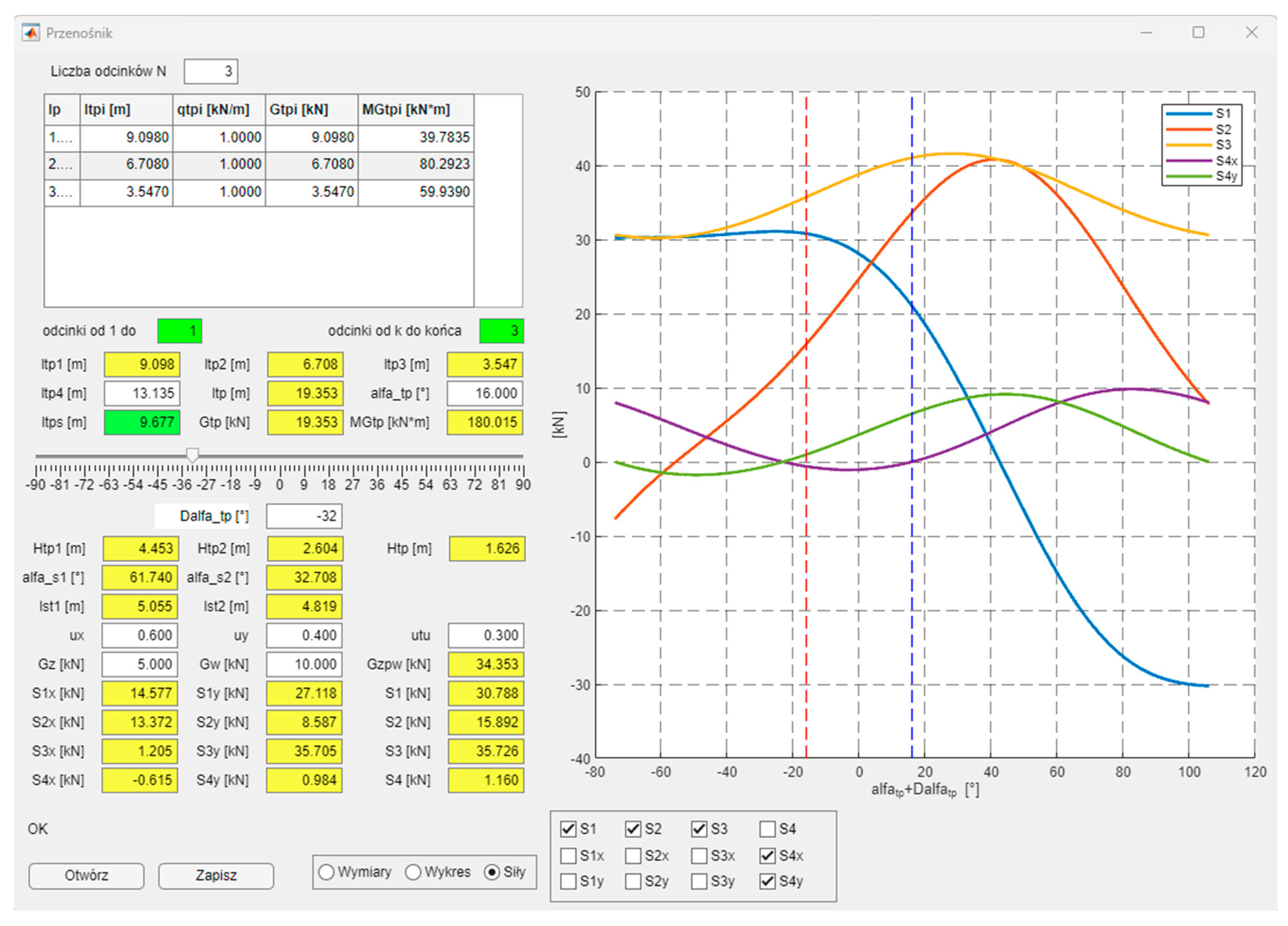
αtp by means of a slider updates the calculations and the schematic drawing of the feeder. The third drawing option includes graphs of
Si forces with their orthogonal components as a function of the sum of angles
αtp and Δ
αtp (
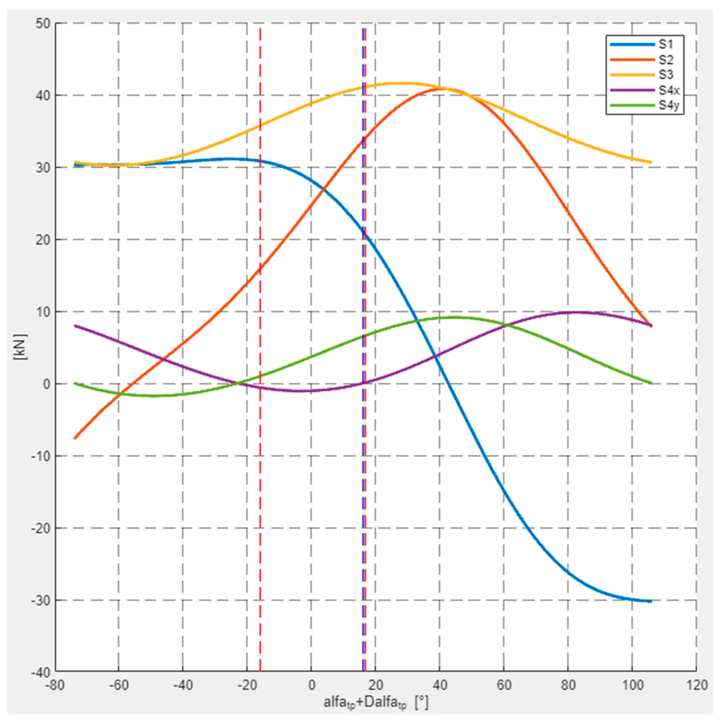
Figure 15).
The values of the forces acting on the feeder depend on its positioning. Graphs of these functions can be helpful in the process of designing the feeder. Twelve “checkboxes” have been placed under the graphs so that the designer can choose which forces they want to depict, also taking into account their orthogonal components. Two vertical dashed lines are also drawn on the graph. The blue line represents the feeder in the neutral position (Δ
αtp = 0°), whereas the red one defines the feeder’s position after taking into account the rotation of the feeder relative to support point 3. Every change in the feeder parameters is updated in the calculations and in the diagrams.
Figure 16 shows the same graphs as in the application (
Figure 15) with an additional red vertical line marked for Δ
αtp = 0.7°.
4. Usage of the Application
The results of the calculations (yellow and green edit boxes on
Figure 13) together with
Figure 14,
Figure 15 and
Figure 16 were obtained with the use of the application in question and the data of a real feeder with a length of 20 m, inclination
αtp = 6°, and a belt width of 1000, placed on V-type stationary supports. (
Figure 10). This feeder is mainly designed to work on inclination
αtp = 16°, in which case Δ
αtp = 0°. This is due to the coupling of the transported material with the belt, where angle
ρtu = 16.7° (54) for
μtu = 0.3, in which case Δ
αtp = 0.7°. Increasing the upward inclination for this type of feeder (Δ
αtp > 0°) is practically impossible in the case of a smooth belt. In the event that the feeder works downwards (Δ
αtp < 0°), its total inclination can reach −32°. The value and sense of force
S4y lead to the conclusion that the feeder’s stability can also be maintained (
Figure 16, green). It can be easily seen that the course of force S
4y is decreasing in the examined range. Conversely, force
S4x increases in value. For Δ
αtp = 0°, force
S4x has a zero value, which is consistent with reality. In the range of permissible belt inclination angles (−32° ˂
αtp ˂ 0.7°), force
S2 has a positive and increasing value. The opposite is true for force
S1, as its value is also positive but decreasing, whereas the resultant value of these forces, i.e., force
S3 for angle
αtp = 16°, reaches its maximum. It should be noted that force
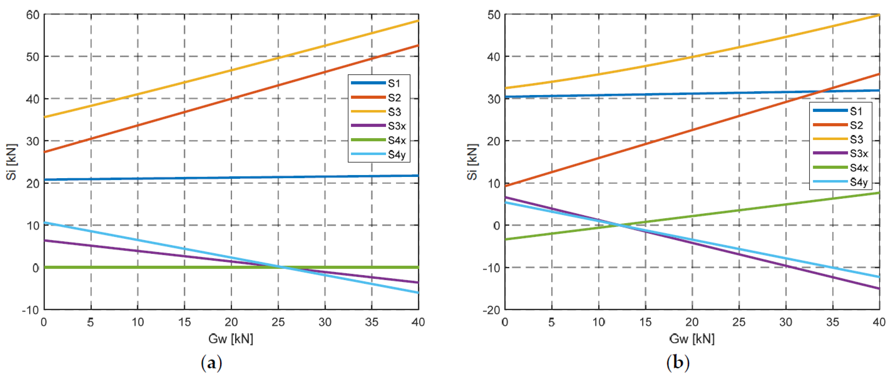
S4y also has a positive value in this range, which leads to the conclusion that the feeder has the required stability. It may change when the weight of the discharge
Gw increases. In such a case, force
S4y has a negative value above weight
Gw = 25.5768 kN, which indicates the loss of stability of the feeder when it is working on an upward slope (Δ
αtp > 0°),
Figure 17a. However, in the case of a feeder working on a downward slope with weight
Gw > 12.2258 kN, force
S4y also has a negative value (Δ
αtp < 0°), which causes loss of stability (
Figure 17b). Of course, the application allows other cases related to the design parameters of the feeder to be considered.
