Article

Polymer Poly (Ethylene Oxide) Additive for High-Stability All-Inorganic CsPbI3−xBrx Perovskite Solar Cells

School of Electronic Information and Artificial Intelligence, Shaanxi University of Science &Technology, Xi’an 710021, China
*
Authors to whom correspondence should be addressed.
Energies 2023, 16(23), 7849; https://doi.org/10.3390/en16237849
Submission received: 2 November 2023 / Revised: 25 November 2023 / Accepted: 28 November 2023 / Published: 30 November 2023
(This article belongs to the Section A2: Solar Energy and Photovoltaic Systems)

Abstract

:
All-inorganic CsPbI3−xBrx perovskite solar cells (PSCs) are becoming increasingly mature due to their excellent optoelectronic properties. However, because of the poor environmental stability of the perovskite material, the device is susceptibly decomposed when exposed to moisture, high temperature, and high illumination. Therefore, a critical task is to address the problem of poor long-term stability in the environment, which serves as a significant obstacle impeding the commercialization of perovskite solar cells. This article introduces the incorporation of PEO into all-inorganic CsPbI3−xBrx perovskites with an advantageous thermal stability. PEO acts as a passivating agent near the grain boundary, and its high viscosity characteristics effectively improve the film-forming properties, leading to a substantial reduction in defects and to improving the surface uniformity. In addition, the grain boundaries that serve as water and oxygen penetration channels are filled, resulting in a substantial improvement in device stability. With 7.5 mg/mL PEO doping into CsPbI3−xBrx, the unencapsulated device maintained its original power conversion efficiency of 98% after being placed in a dark environment of 40% humidity and 25 °C for 10 days. Using PEO effectively enhanced the performance of the devices, with the highest PCE reaching 10.95%, significantly improving environmental stability.

1. Introduction

As a new generation of semiconductor materials, metal halide perovskites have found extensive applications in producing optoelectronic devices, such as solar cells, photodetectors, light-emitting diodes, and lasers, especially in the photovoltaic field [1,2,3,4]. Such diversity in optoelectronics applications is due to inheriting most of the advantages of traditional silicon semiconductors, including a longer carrier diffusion length and lower exciton binding energy [5,6]. The perovskite structure often exhibits an ABX3 composition with a typical ionic structure. As long as the Goldschmidt tolerance coefficient is appropriate, various ions or groups with different sizes and valences can replace the original ions or groups at each position [7,8]. This characteristic offers unlimited possibilities for advancing perovskite solar cells (PSCs). Also, PSCs have many unique characteristics, including their easy acquisition of raw materials, simplicity, and low production cost [9]. Because of these characteristics, PSCs can reach a power conversion efficiency (PCE) of more than 25.7% over a short period of about 10 years [10], which is equal to the level of silicon-based solar cells. Therefore, PSCs have immeasurable potential and broad development prospects in the future. However, although PSCs have made breakthrough achievements, their environmental stability is limited by the inherent features of the perovskite material. The devices are susceptible to decomposition under high humidity, elevated temperatures, and intense illumination [11]. This instability is one of the significant problems hindering the advancement of PSCs.
As PSCs are developed on the basis of dye-sensitized cells, the A position is usually occupied by the organic groups CH3NH3+ (MA+) or HC(NH)2+ (FA+). The pioneering work of all-inorganic PSCs was conducted by Snaith et al. [12]. They used the metal Cs as A-site atoms in PSCs. The introduction of metal Cs efficiently improved the thermal stability of the A site, overcoming the limitation of organic A-site PSCs having trouble working in high-temperature environments [13]. However, the smaller ionic radius of Cs compared with organic groups makes the perovskite structure more susceptible to being destroyed by water and oxygen in the environment [14]. Considerable efforts have been taken to improve the stability of all-inorganic perovskites. Chen et al. used gradient annealing to control the crystallization of CsPbI2Br perovskite precisely. The small amount of Br effectively shrinks the size of the Pb-I octahedron, enhancing the tolerance factor and boosting the stability of the black phase [15]. Furthermore, research has shown that polymers have favorable characteristics, which make them an ideal candidate for enhancing the environmental durability of perovskites. These properties include their strong hydrophobicity, anti-weather ability, and easy preparation [16,17]. By manipulating the long-chain properties of the polymer, the perovskite can be spread out more evenly on the substrate [18]. The molecular chain in the polymer has a large number of ether bonds that exhibit a weak Lewis basicity. These bonds have the capacity to form complexes with uncoordinated Pb2+ ions [19,20]. The most common method for introducing polymers is inserting them into layered structures to serve as moisture barriers. Peng et al. [21] proposed introducing a polymethyl methacrylate (PMMA) layer as a protective barrier between the delicate perovskite material and the Spiro-MeOTAD HTL layer, which has a high propensity for water absorption. This strategy significantly improved the stability of the device. Additionally, the polymer is also an ideal absorbent layer modification material. Zhao et al. [22] reported that the absorber layer film modified with polyethylene glycol (PEG) exhibited good moisture resistance and could sustain a consistent output for an extended duration in a high-humidity setting. Simultaneously, manipulating the crystallization process enabled the growth of bigger grains at densely nucleated locations during the annealing process, hence facilitating the formation of a uniform coating on the TiO2 substrate [23,24].
This work introduced the polymer poly (ethylene oxide) PEO as an absorber layer dopant into CsPbI3−xBrx perovskite films for the first time. As a result of the significant disparity in molecular weight between the perovskite lattice and the PEO material, the PEO does not integrate into the crystal lattice. Instead, it selectively occupies the grain borders and film surface without affecting the structure of the CsPbI3−xBrx lattice structure. The high viscosity of PEO blurs the grain boundaries, hence decreasing the roughness of the surface. Simultaneously, a considerable quantity of ether bonds exhibiting weak Lewis basicity can also have a passivation effect on uncoordinated Pb2+ defects. The inherent hydrophobic property of PEO significantly improves the stability of the perovskite film. Finally, a device with a championship PCE of 10.95%, open circuit voltage (VOC) of 0.96 V, short circuit current density (JSC) of 15.20 mA cm−2, and fill factor (FF) of 0.75 is prepared. Compared with the original CsPbI3−xBrx-based PSCs, the performance improvement mainly contributes to the enhancement of the film quality. In addition, the unpackaged film exhibits the capacity to maintain the necessary black photovoltaic phase under the environment of 20% humidity for two weeks, and the unpackaged device maintains 98% PCE after being stored in a dark environment of 40% humidity and 25 °C for 10 days, indicating a high level of stability.

2. Experimental

2.1. Preparation of Solution

Preparation of CsPbI3−xBrx precursor solution: DMAPbI3 (DMA = (CH3)2NH2+, 0.3854 g), PbBr2 (0.0734 g), and CsI (0.18708 g) were dissolved in DMF in proportion, and the solution concentration was rigorously regulated at 0.6 M. It was then stirred for 8 h at room temperature to ensure complete dissolution.
Preparation of CsPbI3−xBrx-PEO (x mg/mL) precursor solution: Here, 0, 5, 7.5, and 10 mg of PEO particles were dissolved in 1 mL DMF, separately, and then stirred at 70 °C for 12 h until there were no obvious particles. The CsPbI3−xBrx precursor was then mixed at a ratio of 1:1 with the gradient concentration PEO solution. The CsPbI3−xBrx-PEO (x mg/mL) solution was heated and stirred for 12 h at a temperature of 60 °C.
Preparation of the hole transport layer Spiro-MeOTAD Solution: we created a solution of 90 mg Spiro-MeOTAD, 36 μL TBP, and 22 μL lithium salt (520 mg Li-TFSI was dissolved in 1 mL acetonitrile, mixed, and stirred for 6 h, and filtered to obtain a lithium salt solution) which was stirred for 12 h.

2.2. Experimental Procedure

The FTO substrate was cleaned sequentially with deionized water, anhydrous ethanol, acetone, and deionized water in an ultrasonic cleaning machine for 7 min at each step. The TiO2 electron transport layer was grown using the hydrothermal method. Then, 2.5 mL TiCl4 was added to 100 mL of completely frozen deionized water and allowed to melt naturally. Subsequently, the specimen was subjected to a thermal treatment inside an oven set at a temperature of 70 °C for a duration of 70 min. This was followed by annealing at a temperature of 200 °C for 30 min, and was then transferred to a dry environment for storage until later use. To prepare the CsPbI3−xBrx absorbance layer, the 40 μL CsPbI3−xBrx-PEO (x mg/mL) precursor solution was subjected to spin-coating at a speed of 3000 rad/s for a duration of 30 s. Subsequently, the coated layer was annealed at a temperature of 150 °C for 90 min. Spiro-MeOTAD was spin-coated above CsPbI3−xBrx at 4000 rad/s and oxidized in the dark state for 12 h. Finally, Ag electrodes were deposited in vacuum evaporation equipment. The device structure was FTO/TiO2/CsPbI3−xBrx-PEO (x mg/mL)/Spiro-MeOTAD/Ag.

2.3. Characterization

The test equipment was the same as our previous work [25]. The ultraviolet−visible absorption spectrum of the film was measured by UV-2600 (Sunny Optical Technology Co., Ltd., Ningbo, China). The steady-state photoluminescence (PL) spectra were measured using the Hitachi F-7000 (Hitachi, Ltd., Tokyo, Japan) at 535 nm. The SEM images and EDS were tested using FEI Versions 460. The XRD pattern was measured using a Bruker D8 DISCOVER (Bruker, MA, USA) with Cu K radiation (1.5405). The J−V curves, dark J−V curves, output stability, and I−V curves of the only electronic structure device were used in the AM 1.5 Simulated Solar Irradiation System (SAN-EI 100 mW cm−2), the testing software adopted Giant Force Technology Co., Ltd., Beijing, China. Standard 1 Solar, th e SourceMeter used for the test was the Keithley 2400 (Tektronix Inc., Beaverton, OR, USA) source meter, and the tests were conducted in the glove box. The scan rate was 50 mV s−1.

3. Results and Discussion

In the CsPbI3 all-inorganic perovskite system, a small amount of Br entering the lattice could shrink through the Pb-I octahedron. This process effectively stabilized the easy decomposition caused by the small radius Cs [26]. The I to Br ratio of CsPbI3−xBrx used in this study was about 2.85:0.15. The CsPbI3−xBrx-PEO (x mg/mL) perovskite absorption layer was prepared by the one-step spin coating method, and an n-i-p structural device with the structure FTO/TiO2/CsPbI3−xBrx/Spiro-MeOTAD/Ag was obtained finally, as shown in Figure 1a. Figure 1b exhibits the structural diagram of PEO. The molecular formula can be expressed as H-(-OCH2CH2-)n-OH. The ether bonds exhibited weak Lewis basicity, which could blend with the uncoordinated Pb2+ to passivate defects. Influenced by adding PEO, the XPS results (Figure 1b) indicated a shift towards lower binding ionization potentials for the Pb 4f 5/2 and Pb 4f 7/2 peaks. This shift suggests that the PEO allowed Pb to gain some electrons [27], hence passivating the undercoordinated Pb2+ defects. This conclusion was consistent with previous research on polymers [28,29].
In order to further understand the role of PEO in perovskite films, the X-ray diffraction (XRD) patterns with different concentrations of PEO were compared. Some notable peaks were marked in the patterns. As shown in Figure 2a, the main diffraction peaks appearing at 14.8°, 21.1°, and 29.06° corresponded to the (100), (110), and (200) crystal planes [30,31], respectively, proving the formation of typical cubic phase CsPbI3−xBrx. The absence of impurity peaks explained the excellent crystallinity. By magnifying the diffraction peak at 14.8°, it is evident that the peak was without a discernible red shift or blue shift, indicating that the lattice expansion effect could be ignored. In other words, the structure of perovskite remained stable and unchanged, which showed that PEO had not become part of the crystal lattice. It only covered the film surface and grain boundaries. Generally speaking, the half-maximum width (FWHM) of the characteristic peak could be used to measure the crystallinity of a film [32]. As shown in Figure 2b, the characteristic peaks showed a progressive narrowing trend as the amount of PEO increased, and the sharpest peak appeared at 7.5 mg/mL PEO. The FWHM of the peaks with PEO doping ratios of 0, 5, and 7.5 mg/mL were 0.21°, 0.19°, and 0.15°, respectively (the fitted and normalized plots are shown in Figure S1). The gradually narrowing FWHM showed that the crystallinity of the perovskite improved as the PEO doping amount increased. Furthermore, previous studies have demonstrated that adding amorphous polymers to the perovskite precursor solution allows spreading their long molecular chains to be easier. Through this diffusion process, the polymers can build a three-dimensional framework that holds the perovskite crystal in place [33]. Consequently, the perovskite crystal can cover the transmission layer surface more evenly. This factor might also contribute to the rise in perovskite crystallization. Interestingly, as the doping ratio increased during the experiment, the required annealing became longer, which was beneficial for the crystallization of perovskite. The characteristic peak became wider when the doping concentration was 10 mg/mL (FWHM = 0.17°). This enchantment might be attributed to the excessive PEO attached to the grain surface, affecting the test results.
Rough surfaces and uneven crystal growth films harm the performance of a device [34,35]. Hence, the quality of the perovskite absorber layer film is a crucial determinant for obtaining high-performance PSCs. The scanning electron microscopy (SEM) was used to analyze the impact of PEO doping on CsPbI3−xBrx films. Figure 3a shows the SEM image of the original CsPbI3−xBrx film with TiO2 as the substrate. It can be discovered that the CsPbI3−xBrx films have a poor surface uniformity. Although the pinhole phenomena are not readily apparent, the boundaries between neighboring grains are extensive. The grain boundary usually contains defects caused by crystal orientation, broken chemical bonds, and hanging bonds that appear during film formation. The existence of these defects might capture carriers during transfer, leading to serious energy loss [36]. The rough film surface may result in poor contact between the interface absorbing layer and the transport layer, which could cause more leaking current. Figure 3c shows the CsPbI3−xBrx film modified with 7.5 mg/mL PEO. The surface was more even, the grain boundaries were blurred, and the flatness was improved, providing the film an overall dense and continuous surface. This improvement came from the inability of PEO to enter the crystal lattice because it had a high molecular weight and a long chain structure, which only relied on a high viscosity to fill in the grain boundaries and repair the grain boundaries; the top-view and cross-sectional EDS images are shown in Figure S2. In the top-view images, the distribution of carbon elements on the grain surface was relatively uniform, which proved that PEO could cover the grain surface, and the denser points at the grain boundaries proved that PEO filled the grain boundaries. In the cross-sectional image, the presence of carbon elements in the perovskite layer showed that PEO could effectively fill the grain boundaries in the entire film. In addition, uncoordinated Pb2+ was the most common and essential defect in perovskite preparation. Adding moderate PEO could impact the uncoordinated Pb2+ flaws through ether bonding. The thickness of the film had an impact on the performance of the device [37], especially for the electron transport layer and hole transport layer. The number of defects also increased as the thickness of the film became thicker, resulting in an increase in resistance. The image of the cross-sectional SEM test is shown in Figure 3b,d. The thickness of the TiO2 layer was around 60 nm, the perovskite layer was around 400 nm, the Spiro-MeOTAD layer had a thickness of approximately 150 nm, and the Ag layer measured approximately 100 nm. From the above discussion, it seems like a moderate amount of PEO could fill up the grain boundaries, which functioned as water and oxygen penetration paths, which could effectively improve the stability of the device. Simultaneously, the internal uncoordinated defects were passivated, which reduced the non-radiation coincidence and promoted carrier transport.
Then, the absorption performance of the original CsPbI3−xBrx and CsPbI3−xBrx-PEO (7.5 mg/mL) films was characterized, as shown in Figure 4a. The two curves exhibited a high degree of overlap, indicating that the moderate PEO had little impact on the light absorption capabilities. Figure 4b displays the Tauc diagram that corresponds to the UV−VIS spectrum. Both materials had a band gap value of 1.706 eV, similar to previous research results [25].
The J−V curves of the PSCs under different PEO doping amounts are shown in Figure 5a. More data can be found in Table 1. The optimal doping amount of PEO was 7.5 mg/mL, which provided a champion PCE of 10.95%, JSC of 15.20 mA cm−2, VOC of 0.96 V, and FF of 0.75. With the PEO addition amount increasing, VOC did not change much, but JSC showed a trend of first increasing and then decreasing. This was due to the presence of many uncoordinated Pb2+ defects in the original CsPbI3−xBrx device hindering the transmission of photogenerated carriers, the poor film quality of the perovskite layer made it not closely connected with the transmission layer, and the non-radiative coincidence effect was serious. With the 0–7.5 mg/mL PEO added, the passivation effect on grain boundary defects reached the strongest, suppressing non-radiative coincidence. The viscous PEO effectively filled in the uneven surface and resulted in a flatter absorption layer, which promoted the film-forming properties of the transport layer that covered the surface. Tighter surfaces also helped keep charges from building up at the edges of grains and lower the amount of energy lost when the carriers moved [38]. Adding a moderate amount of PEO improved the carrier transport capability, leading to higher JSC in devices, as seen in Figure 5b. On the other hand, the performance improvement was also due to the FF gradually rising. The increase in FF, usually associated with series and parallel resistance, proved that the internal factors that hindered carrier transport were weakened. This reduction led to an improvement in the carrier transport capabilities. Additionally, the FF designation meant that the device quality had a better overlay. The JSC decreased when the addition amount was raised to 10 mg/mL. This phenomenon was because the excess PEO attached to the surface, hindering carrier transmission due to its low conductivity. Figure S3 shows the J−V curves of devices scanned from different directions. The hysteresis index (HI = (PCEreversePCEforward)/PCEreverse) of CsPbI3−xBrx-PEO (7.5 mg/mL)-based devices (0.074) was less than that of the CsPbI3−xBrx-based devices (0.187). The lower HI explained the lower ion migration and superior stability in CsPbI3−xBrx-PEO (7.5 mg/mL) perovskite films.
A stable output is also an essential parameter for solar cells. Figure 6a observed that CsPbI3−xBrx-PEO (7.5 mg/mL)-based devices had a n output curve within 300 s at the maximum power point (Vmpp = 0.76 V, sample interval: 0.3 s). The JSC output demonstrated consistent maintenance at around 14.47 mA cm−2, and the efficiency was also maintained at the optimal output. The stable output indicated the stability of the perovskite structure. In order to further explore the impact of PEO on the internal defects of the perovskite absorption layer, pure electronic devices with a structure of FTO/TiO2/CsPbI3−xBrx/PCBM/Ag were prepared. Figure 6b shows the dark current results conducted on the two groups of devices. It can be seen that the CsPbI3−xBrx-PEO (7.5 mg/mL)-based devices had a low dark current, indicating fewer carriers were captured by defect energy levels internally, and more photogenerated carriers could move to the two poles. Figure 6c shows the quantitative lower voltage required for filling defects, representing the existence of fewer defects inside the perovskite film. The calculation of Nt (trap-state density) uses the following formula [39]:
N t = 2 ε 0 ε V TFL e L 2
VTFL (trap-filled limiting voltage) is obtained from the patterns, ε is the relative dielectric constant, the value of e is 1.6 × 10⁻¹⁹, and L is the crystal thickness. The calculated Nt of the CsPbI3−xBrx-PEO (7.5 mg/mL)-based device was 1.70 × 1016 cm−3, lower than the 1.85 × 1016 cm−3 of the CsPbI3−xBrx-based device. These improvements were attributed to the passivation of uncoordinated Pb2+ defects by PEO, as well as the smoother surface and reduced visibility of the grain boundaries, which caused a decrease in energy loss. Figure 6d shows the results of the photoluminescence (PL) test for the perovskite film, the device structure for the test was FTO/TiO2/CsPbI3−xBrx-PEO (x mg/mL). Generally speaking, the non-radiative recombination phenomenon of photogenerated carriers caused by defects can reduce the fluorescence yield in PL testing [40]. The test results indicate that the original CsPbI3−xBrx-based device had the lowest PL intensity. As the doping ratio of PEO increased, the PL intensity showed an increasing trend, which proved that the addition of PEO effectively passivated defects. This finding was consistent with previous additions of the polymer PEG to perovskite films [41]. The 7.5 mg/mL PEO could successfully passivate defects, reduce defects, and blur grain boundaries, facilitating more photogenerated carriers captured by the electrodes. These results were consistent with the SEM and J−V analysis.
Figure 7a,b shows the water contact angle of the CsPbI3−xBrx and CsPbI3−xBrx-PEO (7.5 mg/mL) films. The contact angle of the CsPbI3−xBrx film was 50.422°, which was much less than the 90.362° of the CsPbI3−xBrx-PEO (7.5 mg/mL) films. This improvement was due to the hydrophobicity of films successfully inherited from PEO. A film with a good hydrophobicity was beneficial for improving the overall stability of the device. Figure 7c shows the photograph aged in the environment (temperature: 25–30 °C, humidity: 30–40%) of the CsPbI3−xBrx and CsPbI3−xBrx-PEO (7.5 mg/mL) films. Over time, the CsPbI3−xBrx films exhibited a serious phase change. As a comparison, there was almost no change in the CsPbI3−xBrx-PEO (7.5 mg/mL) films. During the subsequent observation about two weeks later, a discernible yellow phase appeared on the CsPbI3−xBrx-PEO (7.5 mg/mL) films.
In order to eliminate uncertainties with experimental and testing, box charts were used to summarize the optical parameters of 30 devices. The optimized indicates the CsPbI3−xBrx-PEO (7.5 mg/mL)-based devices and reference indicates the CsPbI3−xBrx-based devices. The JSC distribution of the CsPbI3−xBrx-PEO (7.5 mg/mL)-based devices appeared to be more concentrated, but the average value was slightly lower than that of the CsPbI3−xBrx-based devices. This phenomenon was due to the polymer PEO hindering the carrier transport performance. The FF of CsPbI3−xBrx-PEO (7.5 mg/mL)-based devices showed a higher and denser distribution, proving the improvement in the overall quality of the device. The 7.5 mg/mL PEO reached a critical value between defect passivation and hindering carrier transport, minimizing current loss while improving device quality as much as possible. As shown in Figure 8c, the PCE of the device improved significantly. At the same time, due to the enhanced stability of each parameter under the influence of PEO, PCE also showed better repeatability.
Figure 8d shows the absorption properties of CsPbI3−xBrx and CsPbI3−xBrx-PEO (7.5 mg/mL) films stored in a dark environment for 100 h. The absorption property of the CsPbI3−xBrx-(7.5 mg/mL) film exhibited little alterations, and the property of the CsPbI3−xBrx film decreased significantly, demonstrating that the CsPbI3−xBrx-PEO (7.5 mg/mL) films had an excellent environmental stability. The thermal stability of the devices exposed to 80 °C is shown in Figure 8e. Based on the good thermal stability of all-inorganic perovskite, PEO passivated the defects, stabilizing the entire perovskite structure and further enhancing the thermal stability. Figure 8f shows the PCE decline curve after being stored in a dark environment for 10 days. Compared with the 80% drop in CsPbI3−xBrx-based devices, the CsPbI3−xBrx-PEO (7.5 mg/mL)-based devices did not change much. The enhanced stability was due to the highly hydrophobic polymer PEO filling in the grain boundary, which was the main path for water and oxygen penetration.

4. Conclusions

In summary, the all-inorganic CsPbI3−xBrx perovskite film was prepared by the one-step spin coating method and used as an absorber layer in perovskite solar cell devices. Moderate PEO successfully improved the long-term stability and performance of the devices. PEO acted as a passivating agent at the grain boundary, the high viscosity property effectively improves film-forming properties. The defects in the CsPbI3−xBrx film were passivated significantly, improving the surface uniformity. The grain boundaries that serve as water and oxygen penetration channels were filled, leading to a notable improvement in stability. Finally, the device champion PCE was 10.95%, JSC was 15.20 mA cm−2, VOC was 0.96 V, and FF was 0.75. The unpackaged device maintained 98% PCE after being stored in a dark environment at 40% humidity and 25 °C for 10 days, significantly improving environmental stability. This is the first time PEO appeared as a passivator in an all-inorganic perovskite system solar cells. This work provides a new opportunity for the further commercialization of PSCs.

Supplementary Materials

The following supporting information can be downloaded at: https://www.mdpi.com/article/10.3390/en16237849/s1. Figure S1: The (a) fitted and (b) normalized Peaks at 14.8°. Figure S2: EDS images of the CsPbI3−xBrx-PEO (7.5 mg/mL) films: (a) Top-view and (b) cross-sectional. Figure S3: J−V curves scanned from different directions: (a) CsPbI3−xBrx-based devices and (b) CsPbI3−xBrx-PEO (7.5 mg/mL)-based devices.

Author Contributions

Project administration, F.-H.Z.; software, J.H.; methodology, data curation, writing—original draft preparation, writing—review and editing, C.-Y.C.; visualization, T.X. and H.W.; supervision, X.W. and C.-L.J.; visualization, C.-F.Z.; conceptualization and funding acquisition, F.-H.Z. and J.H. All authors have read and agreed to the published version of the manuscript.

Funding

This research was funded by the Natural Science Foundation of China (no. 61904100, 11604194) and The Education Department of Shaanxi Province serves the Local Special Plan Project (no. 17JF006).

Data Availability Statement

All data that support the findings of this study are included within the article.

Conflicts of Interest

The authors declare no conflict of interest.

References

  1. Jayan, K.D.; Sebastian, V.; Kurian, J. Simulation and optimization studies on CsPbI3 based inorganic perovskite solar cells. Sol. Energy 2021, 221, 99–108. [Google Scholar] [CrossRef]
  2. Bai, D.; Zhang, J.; Jin, Z.; Bian, H.; Wang, K.; Wang, H.; Liang, L.; Wang, Q.; Liu, S. Interstitial Mn2+-driven high-aspect-ratio grain growth for low-trap-density microcrystalline films for record efficiency CsPbI2Br solar cells. ACS Energy Lett. 2018, 3, 970–978. [Google Scholar] [CrossRef]
  3. Zhou, S.; Tang, R.; Yin, L. Slow-photon-effect-induced photoelectrical-conversion efficiency enhancement for carbon-quantum-dot-sensitized inorganic CsPbBr3 inverse opal perovskite solar cells. Adv. Mater. 2017, 29, 1703682. [Google Scholar] [CrossRef]
  4. Li, B.; Zhang, Y.; Fu, L.; Yu, T.; Zhou, S.; Zhang, L.; Yin, L. Surface passivation engineering strategy to fully-inorganic cubic CsPbI3 perovskites for high-performance solar cells. Nat. Commun. 2018, 9, 1076. [Google Scholar] [CrossRef]
  5. Xu, Z.; Lu, D.; Liu, F.; Lai, H.; Wan, X.; Zhang, X.; Liu, Y.; Chen, Y. Phase Distribution and Carrier Dynamics in Multiple-Ring Aromatic Spacer-Based Two-Dimensional Ruddlesden–Popper Perovskite Solar Cells. ACS Nano 2020, 14, 4871–4881. [Google Scholar] [CrossRef]
  6. Yu, Z.; Wang, J.; Chen, B.; Uddin, M.A.; Ni, Z.; Yang, G.; Huang, J.-S. Solution-Processed Ternary Tin (II) Alloy as Hole-Transport Layer of Sn–Pb Perovskite Solar Cells for Enhanced Efficiency and Stability. Adv. Mater. 2022, 34, 2205769. [Google Scholar] [CrossRef]
  7. Yi, Z.; Ladi, N.H.; Shai, X.; Li, H.; Shen, Y.; Wang, M. Will organic–inorganic hybrid halide lead perovskites be eliminated from optoelectronic applications? Nanoscale Adv. 2019, 1, 1276–1289. [Google Scholar] [CrossRef]
  8. Chen, Y.; Sun, Y.; Peng, J.; Tang, J.; Zheng, K.; Liang, Z. 2D Ruddlesden–Popper Perovskites for Optoelectronics. Adv. Mater. 2017, 30, 1703487. [Google Scholar] [CrossRef]
  9. Huang, J.; Chen, C.; Li, Y.; Wang, H.; Zhang, F.; Zhang, D. BT-MA0.6FA0.4PbI3–xClx Unsymmetrical Perovskite for Solar Cells with Superior Stability and PCE over 23%. ACS Appl. Energy Mater. 2022, 5, 11058–11066. [Google Scholar] [CrossRef]
  10. Park, J.; Kim, J.; Yun, H.-S.; Paik, M.J.; Noh, E.; Mun, H.J.; Kim, M.G.; Shin, T.J.; Seok, S.I. Controlled growth of perovskite layers with volatile alkylammonium chlorides. Nature 2023, 616, 724–730. [Google Scholar] [CrossRef]
  11. Boyd, C.C.; Cheacharoen, R.; Leijtens, T.; McGehee, M.D. Understanding Degradation Mechanisms and Improving Stability of Perovskite Photovoltaics. Chem. Rev. 2019, 119, 3418–3451. [Google Scholar] [CrossRef] [PubMed]
  12. Eperon, G.E.; Paternò, G.M.; Sutton, R.J.; Zampetti, A.; Haghighirad, A.A.; Cacialli, F.; Snaith, H.J. Inorganic caesium lead iodide perovskite solar cells. J. Mater. Chem. A 2015, 3, 19688–19695. [Google Scholar] [CrossRef]
  13. Chen, H.; Xiang, S.; Li, W.; Liu, H.; Zhu, L.; Yang, S. Inorganic Perovskite Solar Cells: A Rapidly Growing Field. Sol. RRL 2018, 2, 1700188. [Google Scholar] [CrossRef]
  14. Gao, C.; Shao, Z.; Sun, X.; Li, Z.; Rao, Y.; Lv, P.; Wei, Y.; Chen, C.; Liu, D.; Wang, X.; et al. Fabrication and Characterization of FAxCs1−xPbI3 Polycrystal Perovskite Solar Cells. Sol. RRL 2021, 5, 2100166. [Google Scholar] [CrossRef]
  15. Chen, W.; Chen, H.; Xu, G.; Xue, R.; Wang, S.; Li, Y.; Li, Y. Precise Control of Crystal Growth for Highly Efficient CsPbI2Br Perovskite Solar Cells. Joule 2019, 3, 191–204. [Google Scholar] [CrossRef]
  16. Weerasinghe, H.C.; Dkhissi, Y.; Scully, A.D.; Caruso, R.A.; Cheng, Y.-B. Encapsulation for improving the lifetime of flexible perovskite solar cells. Nano Energy 2015, 18, 118–125. [Google Scholar] [CrossRef]
  17. Wang, S.; Zhang, Z.; Tang, Z.; Su, C.; Huang, W.; Li, Y.; Xing, G. Polymer strategies for high-efficiency and stable perovskite solar cells. Nano Energy 2021, 82, 105712. [Google Scholar] [CrossRef]
  18. Zhang, Y.; Zhuang, X.; Zhou, K.; Cai, C.; Hu, Z.; Zhang, J.; Zhu, Y. Amorphous polymer with C=O to improve the performance of perovskite solar cells. J. Mater. Chem. C 2017, 5, 9037–9043. [Google Scholar] [CrossRef]
  19. Bi, D.; Yi, C.; Luo, J.; Décoppet, J.-D.; Zhang, F.; Zakeeruddin, S.M.; Li, X.; Hagfeldt, A.; Grätzel, M. Polymer-templated nucleation and crystal growth of perovskite films for solar cells with efficiency greater than 21%. Nat. Energy 2016, 1, 16142. [Google Scholar] [CrossRef]
  20. Han, T.-H.; Lee, J.-W.; Choi, C.; Tan, S.; Lee, C.; Zhao, Y.; Dai, Z.; De Marco, N.; Lee, S.-J.; Bae, S.-H.; et al. Perovskite-polymer composite cross-linker approach for highly-stable and efficient perovskite solar cells. Nat. Commun. 2019, 10, 520. [Google Scholar] [CrossRef]
  21. Wu, J.; Cui, Y.; Yu, B.; Liu, K.; Li, Y.; Li, H.; Shi, J.; Wu, H.; Luo, Y.; Li, D.; et al. A Simple Way to Simultaneously Release the Interface Stress and Realize the Inner Encapsulation for Highly Efficient and Stable Perovskite Solar Cells. Adv. Funct. Mater. 2019, 29, 1905336. [Google Scholar] [CrossRef]
  22. Zhao, Y.; Wei, J.; Li, H.; Yan, Y.; Zhou, W.; Yu, D.; Zhao, Q. A polymer scaffold for self-healing perovskite solar cells. Nat. Commun. 2016, 7, 10228. [Google Scholar] [CrossRef] [PubMed]
  23. Peng, J.; Khan, J.I.; Liu, W.; Ugur, E.; Duong, T.; Wu, Y.; Shen, H.; Wang, K.; Dang, H.; Aydin, E.; et al. A Universal Double-Side Passivation for High Open-Circuit Voltage in Perovskite Solar Cells: Role of Carbonyl Groups in Poly(methyl methacrylate). Adv. Energy Mater. 2018, 8, 1801208. [Google Scholar] [CrossRef]
  24. Zhang, M.; Li, T.; Zheng, G.; Li, L.; Qin, M.; Zhang, S.; Zhou, H.; Zhan, X. An amino-substituted perylene diimide polymer for conventional perovskite solar cells. Mater. Chem. Front. 2017, 1, 2078–2084. [Google Scholar] [CrossRef]
  25. Shi, K.; Zhang, F.; Zhang, M.; Chen, C.; Zhang, W.; Huang, J. Fluorine-containing organic ammonium salt-doped inverted inorganic perovskite solar cells. Semicond. Sci. Technol. 2022, 37, 095014. [Google Scholar] [CrossRef]
  26. Liu, C.; Li, W.; Zhang, C.; Ma, Y.; Fan, J.; Mai, Y. All-Inorganic CsPbI2Br Perovskite Solar Cells with High Efficiency Exceeding 13%. J. Am. Chem. Soc. 2018, 140, 3825–3828. [Google Scholar] [CrossRef] [PubMed]
  27. Ren, M.; Chen, C.; Tang, Y.; Yang, H.; Wang, H.; Huang, J.; Zhang, D. Improve Perovskite Solar Cell Stability and Efficiency via Multifunctional Multiple-Ring Aromatic Dopant Passivation. Sol. RRL 2023, 7, 2300163. [Google Scholar] [CrossRef]
  28. Zheng, H.; Xu, X.; Xu, S.; Liu, G.; Chen, S.; Zhang, X.; Chen, T.; Pan, X. The multiple effects of polyaniline additive to improve the efficiency and stability of perovskite solar cells. J. Mater. Chem. C 2019, 7, 4441–4448. [Google Scholar] [CrossRef]
  29. Zheng, L.; Wang, K.; Zhu, T.; Yang, Y.; Chen, R.; Gu, K.; Liu, C.; Gong, X. High-Performance Perovskite Solar Cells by One-Step Self-Assembled Perovskite-Polymer Thin Films. ACS Appl. Energy Mater. 2020, 3, 5902–5912. [Google Scholar] [CrossRef]
  30. Zhang, W.; Xiong, J.; Li, J.; Daoud, W.A. Organic Dye Passivation for High-Performance All-Inorganic CsPbI1.5Br1.5 Perovskite Solar Cells with Efficiency over 14%. Adv. Energy Mater. 2020, 11, 2003585. [Google Scholar] [CrossRef]
  31. Xu, Y.; Li, G.; Li, R.; Jing, Y.; Zhang, H.; Wang, X.; Du, Z.; Wu, J.; Lan, Z. PbS/CdS heterojunction thin layer affords high-performance carbon-based all-inorganic solar cells. Nano Energy 2022, 95, 106973. [Google Scholar] [CrossRef]
  32. Wang, J.; Li, N.; Zhong, C.; Miao, J.; Huang, Z.; Yu, M.; Hu, Y.X.; Luo, S.; Zou, Y.; Li, K.; et al. Metal-Perturbed Multiresonance TADF Emitter Enables High-Efficiency and Ultralow Efficiency Roll-Off Nonsensitized OLEDs with Pure Green Gamut. Adv. Mater. 2022, 35, 2208378. [Google Scholar] [CrossRef] [PubMed]
  33. Zuo, L.; Guo, H.; deQuilettes, D.W.; Jariwala, S.; De Marco, N.; Dong, S.; DeBlock, R.; Ginger, D.S.; Dunn, B.; Wang, M.; et al. Polymer-modified halide perovskite films for efficient and stable planar heterojunction solar cells. Sci. Adv. 2017, 3, e1700106. [Google Scholar] [CrossRef] [PubMed]
  34. Dong, W.; Qiao, W.; Xiong, S.; Yang, J.; Wang, X.; Ding, L.; Yao, Y.; Bao, Q. Surface Passivation and Energetic Modification Suppress Nonradiative Recombination in Perovskite Solar Cells. Nano-Micro Lett. 2022, 14, 108. [Google Scholar] [CrossRef]
  35. Zhao, L.; Tang, P.; Luo, D.; Dar, M.I.; Eickemeyer, F.T.; Arora, N.; Hu, Q.; Luo, J.; Liu, Y.; Zakeeruddin, S.M.; et al. Enabling full-scale grain boundary mitigation in polycrystalline perovskite solids. Sci. Adv. 2022, 8, eabo3733. [Google Scholar] [CrossRef]
  36. Tan, X.; Liu, X.; Liu, Z.; Sun, B.; Li, J.; Xi, S.; Shi, T.; Tang, Z.; Liao, G. Enhancing the optical, morphological and electronic properties of the solution-processed CsPbIBr2 films by Li doping for efficient carbon-based perovskite solar cells. Appl. Surf. Sci. 2020, 499, 143990. [Google Scholar] [CrossRef]
  37. Tang, S.; Peng, Y.; Zhu, Z.; Zong, J.; Zhao, L.; Yu, L.; Chen, R.; Li, M. Simultaneous Bulk and Surface Defect Passivation for Efficient Inverted Perovskite Solar Cells. J. Phys. Chem. Lett. 2022, 13, 5116–5122. [Google Scholar] [CrossRef]
  38. Liu, X.; Fu, S.; Zhang, W.; Xu, Z.; Li, X.; Fang, J.; Zhu, Y. A Universal Dopant-Free Polymeric Hole-Transporting Material for Efficient and Stable All-Inorganic and Organic–Inorganic Perovskite Solar Cells. ACS Appl. Mater. Interfaces 2021, 13, 52549–52559. [Google Scholar] [CrossRef]
  39. Wang, K.; Gao, C.; Xu, Z.; Tian, Q.; Gu, X.; Zhang, L.; Zhang, S.; Zhao, K.; Liu, S. In-Situ Hot Oxygen Cleansing and Passivation for All-Inorganic Perovskite Solar Cells Deposited in Ambient to Breakthrough 19% Efficiency. Adv. Funct. Mater. 2021, 31, 2101568. [Google Scholar] [CrossRef]
  40. Ran, C.; Gao, W.; Li, J.; Xi, J.; Li, L.; Dai, J.; Yang, Y.; Gao, X.; Dong, H.; Jiao, B.; et al. Conjugated Organic Cations Enable Efficient Self-Healing FASnI3 Solar Cells. Joule 2019, 3, 3072–3087. [Google Scholar] [CrossRef]
  41. Chang, C.; Chu, C.; Huang, Y.; Huang, C.; Chang, S.; Chen, C.-A.; Chao, C.; Su, W. Tuning Perovskite Morphology by Polymer Additive for High Efficiency Solar Cell. ACS Appl. Mater. Interfaces 2015, 7, 4955–4961. [Google Scholar] [CrossRef] [PubMed]
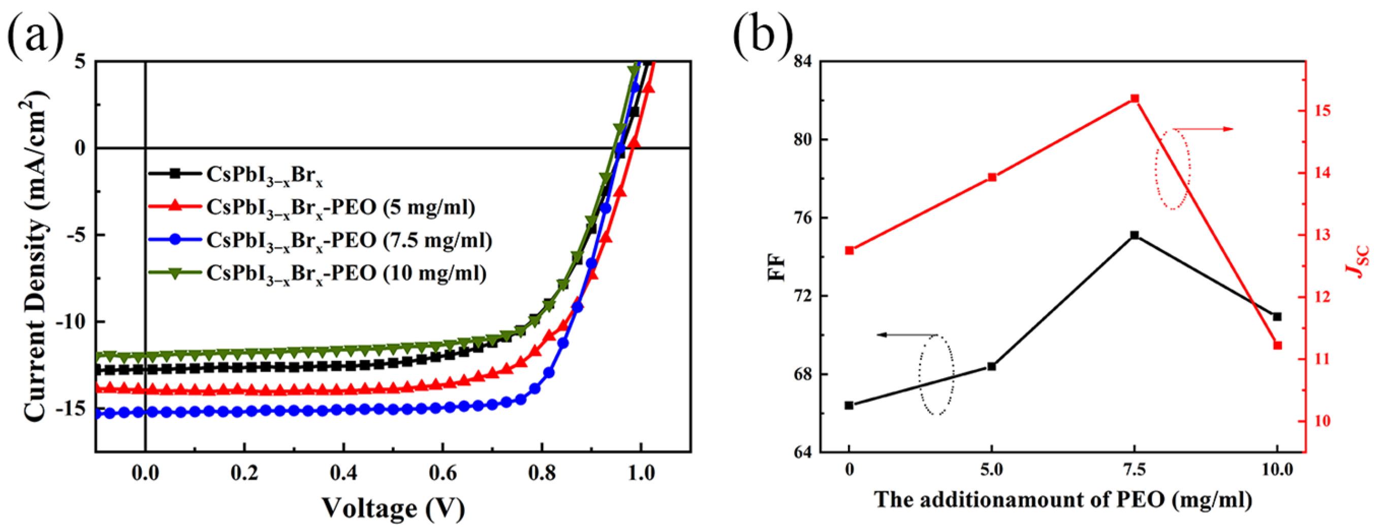
Figure 1. (a) Schematic diagram of PSCs structure and passivation mechanism. (b) Molecular diagram of PEO. (c) Typical XPS of Pb.
Energies 16 07849 g001
Figure 2. The X-ray diffraction patterns of (a) CsPbI3−xBrx-PEO (x mg/mL) films. (b) Partial diffraction peaks with CsPbI3−xBrx-PEO (x mg/mL) films.
Energies 16 07849 g002
Figure 3. The top-view and cross-section SEM images. (a,b) CsPbI3−xBrx films. (c,d) CsPbI3−xBrx-PEO (7.5 mg/mL) films.
Energies 16 07849 g003
Figure 4. (a) UV−VIS absorbance of perovskite films. (b) Tauc diagram corresponding to the absorption spectrum.
Energies 16 07849 g004
Figure 5. (a) J−V curves of devices under various concentrations of PEO. (b) FF and JSC change with the amount of PEO.
Energies 16 07849 g005
Figure 6. (a) Output Stability for 300 s. (b) Dark J−V curves. (c) I−V curves of the only electronic structure device. (d) Photoluminescence spectra.
Energies 16 07849 g006
Figure 7. Water contact angle with (a) CsPbI3−xBrx films. (b) CsPbI3−xBrx-PEO (7.5 mg/mL) films. (c) Photos of film aging within 64 h.
Energies 16 07849 g007
Figure 8. Box charts of (a) FF, (b) JSC, and (c) PCE (d) UV−VIS absorbance of perovskite films after 100 h under a dark environment. Normalized PCEs of CsPbI3−xBrx and CsPbI3−xBrx-PEO (7.5 mg/mL)-based devices for the environment: (e) thermal and (f) stability evaluations.
Energies 16 07849 g008
Table 1. The parameters of devices with different ratios of PEO.
Devices
PEO Ratio
VOC
(V)
JSC
(mA cm−2)
Fill
Factor
Rs/Rsh
(Ω/cm−2)
PCE(%)
Average
PCE(%)
Best
(0 mg/mL)0.9612.750.65119.70/34,047.627.067.94
(5 mg/mL)0.9813.940.68100.41/6651.168.269.37
(7.5 mg/mL)0.9615.200.7582.41/16,627.919.9310.95
(10 mg/mL)0.9511.220.70101.05/8909.657.157.95
Disclaimer/Publisher’s Note: The statements, opinions and data contained in all publications are solely those of the individual author(s) and contributor(s) and not of MDPI and/or the editor(s). MDPI and/or the editor(s) disclaim responsibility for any injury to people or property resulting from any ideas, methods, instructions or products referred to in the content.

