Abstract
As the major power source for electric vehicles (EVs), lithium-ion batteries (LiBs) suffer from the degradation of technical performance and safety at low temperatures, which restricts the popularization of EVs in frigid regions. Thus, this study developed an extremely fast electromagnetic induction heating system in order to improve the poor performance of LiBs in cold weather. An electrochemical–thermal coupling model (ETCM), validated against the experimental results of charge and discharge, which successfully predicted LiB voltage, temperature, and other physical characteristics at various ambient temperatures, was established in COMSOL Multiphysics 6.0 as a development tool for evaluating the heating effect of the system. When the copper coil is subjected to a SAC (sinusoidal alternating current) of 8 A and 50 Hz, the LiB can be heated from 243.15 to 293.15 K within 6 min with an instantaneous temperature increase rate of 0.263 K/s and a homogeneous temperature distribution. The results of the capacity calibration, cyclable lithium detection, and HPPC simulation show that the heating method can visibly increase the Li+ concentration inside the active particle, and there was only a tiny concentration gradient on the surface of the particle. In addition, the internal resistance was approximately a quarter of that without heating; therefore, both the discharge energy and specific power boost were two times higher than the original level. Compared to the normal charge–discharge cycles at 293.15 K, the capacity retention of the LiB only decreased by 0.23% after 60 consecutive heating cycles, so the heating method can balance the temperature rise, work capacity, and LiB health. Furthermore, the improvements in the thermal insulation condition and material thermal conductivity are two feasible ways to optimize the temperature-increase effect.
1. Introduction
In the context of the global energy crisis and environmental pollution, new energy vehicles, especially zero-emission and pollution-free EVs, are gradually replacing traditional internal combustion-energy vehicles and will become a mainstream means of transportation [1,2]. At present, LiBs have been widely applied in EVs as the major power source due to their advantages of high energy density, low self-discharge, no memory effect, etc. [3]. However, the performance of LiBs faces serious degradation at low temperatures (subzero Celsius), and the significantly increased internal resistance of LiBs leads to a substantial loss of pulse power and usable energy for the slow intercalation and de-intercalation of Li+, low-electrolyte electrical conductivity and Li+ diffusivity in the negative electrode, and large solid-electrolyte interface (SEI) film impedance, which cause a reduction in the cruise range and restricts the applicability of EVs in severely cold regions [4,5,6,7]. On the other hand, it is difficult for LiBs to be charged and discharged at low temperatures, and if charging is forcibly performed, lithium is likely to be deposited in the form of lithium dendrites on the surface of the negative electrodes, which may result in an internal short circuit, causing the thermal runaway and irreversible energy decline in the LiBs [8,9]. Therefore, on the premise of ensuring safety, rapid heating of LiBs up to a charging/discharging-friendly temperature is a longstanding goal of battery management systems (BMSs) in order to improve LiBs′ poor performance in cold weather.
Defining the coupling relationship between electrical and thermal processes is essential for developing a reliable heating scheme [10]. Zhang et al. [9] presented a lumped energy conservation method based on the equivalent electrical circuit model (EECM), considering the effects of ohmic resistance, SEI film resistance, impedance for the charge transfer process at the solid–liquid interface, and other declining factors on LiB performance, which could accurately calculate the LiB temperature rise during the alternating current (AC) heating process at different amplitudes and frequencies. The maximum deviation between the experimental data and calculated results was less than 1.5 K, and the model had high computing efficiency because it could directly solve the heat production problem using the real part of the impedance; thus, Zhang et al. developed a SAC heating system on the basis of this model. Ruan et al. [11,12] developed a reduced electro-thermal model in the frequency domain, when the polarization voltage and AC frequency were set as constants, which could not only predict the temperature of LiBs by adjusting the AC amplitude at a certain temperature increase interval but also stimulate the battery voltage evolution with small errors. Although the EECM has fewer calculation parameters, a simple structure, and low computational complexity, the relevant parameters lack clear physical meaning and are difficult to adapt to the time-variable nonlinear behaviors of LiBs in a broad range, so it is incapable of reflecting the internal state of LiBs [13,14].
Newman and Doyle et al. [15,16] proposed a P2D model based on the theory of porous electrodes, which could not only precisely describe the electrochemical reaction process from the reaction mechanism but also monitor and control the internal working status of batteries. This model has been widely applied to commercial simulation software as a battery design and development tool, including COMSOL Multiphysics 6.0, SIMCENTER BDS 2022.1, GT-Autolion 2022, etc. Xiong et al. [17] developed an ETCM to design an intermittent fast heating system, which could accurately estimate the variations in voltage, current, and temperature within the heating process under various initial conditions; this model could predict heating results without experiments and provide theoretical guidance for the development of heating tests. Wang et al. [18] used an ETCM to develop a self-heating lithium-ion battery (SHLB), explored the key factors affecting self-heating time and energy, and designed a more efficient multi-sheet cell. Ren et al. [7] added lithium-plating and -stripping reactions to the interfacial reaction kinetics equations on the basis of the ETCM, which can reflect the capacity loss caused by lithium plating and stripping and quantify the amount of reversible lithium; in addition, it could characterize the effects of ambient temperature and relaxation time on reversible lithium.
The methods to improve the poor low-temperature performance of LiBs include, but are not limited to, heating, developing advanced electrode materials, and the addition of additives to an electrolyte; however, due to the present manufacturing process for batteries, it is difficult to promote low-temperature performance through the materials, so using auxiliary heating has become a feasible research direction [19,20,21]. The heating methods for LiBs can be divided into external and internal heating based on the heat sources [22].
External heating refers to the application of heaters to increase LiB temperature through an external medium or direct contact [1,23], including fluid heating [24,25,26], PCM heating [27,28], Peltier effect heating [29,30], wild-line metal film heating [21,31,32], etc. Li et al. [25] designed power battery packs with a low-temperature heating system using a liquid-cooling structure; when the battery temperature was below 263.15 K, the system started the heating mode, and the system entered the mode of heat insulation once the battery and ambient temperatures were below 288.15 and 263.15 K, respectively. Through the system, the battery pack can be heated from 243.15 to 283.15 K within 2500 s, with the temperature difference between signal cells only reaching 1 K. Zhang et al. [32] proposed a wild-line metal film-heating approach, in which, copper-plated FR4 panels are placed on the two sides of the square battery pack with the largest surface area, and the heat generated by the current passing through the external copper wires was transferred to the pack homogeneously through the copper films. The temperature of the batteries outside the pack rose from 233 K to 273 K within 4500 s, and after the heating process, the pack can release 50% of the rated capacity. Alaoui et al. [29,30] used the Peltier effect to design a heat pump to warm up battery packs; when the ambient temperature was 290.15 K, the temperature of the packs in front of and behind the vehicle increased by 20 K and 12 K after the heating process, respectively. Although the external heating method can be implemented easily, reliably, and safely, the temperature increase rate is relatively low, and the large temperature gradient generated by uneven temperature distribution inside the LiB can give rise to the electrode degradation and the irreversible decrease in the LiB’s cycle lifetime [33,34].
Conversely, through current excitation to LiBs, the internal approach heats LIBs using the heat generated inside the LiBs themselves, which has a higher heat generation rate, shorter heat transfer path, and better temperature uniformity inside the LiBs than external methods [1,11,35,36]. Wang et al. [37] introduced the concept of SHLB, in which a Ni foil is inserted with two tabs attached to the LiB. They realized the conversion between an all-climate battery (ACB) and a traditional LiB by adjusting the temperature-controlled switch between the activation tab and the negative terminal; a large amount of the heat inside the LiB came from the Joule heat generated by the instantaneous short circuit in the ACB mode. The new structure can rapidly activate the LiB from 243.15 K to 273.15 K within 30 s at the expense of 5.5% of the battery capacity. On this basis, Wang et al. [18] developed a multi-sheet cell, with a pouch structure incorporated with multiple Ni foils inside a battery rather than the single Ni sheet inserted in the center. Compared to the one-sheet cell, the two-sheet and three-sheet structures can achieve a nearly 25% and 30% improvement in terms of both activation time and capacity consumption, respectively. Nevertheless, the SHLB requires large changes to be made to the traditional LiB structure, which is difficult to achieve in engineering.
Because of the short-term high-current self-discharge of LiBs, Xiong, Chen, et al. [17,23] presented an intermittent electric-triggered fast heating system; the test results indicated that this method can increase the LiB temperature by 20 K within 87 s, and the peak temperature increase rate was 0.65 K/s. In addition, the standard deviation of the LiB temperature rise was less than 2.7 K after heating the battery pack, suggesting that this method had fast heat production and stable temperature distribution. Although this method can obtain a sufficient temperature rise and consistency, the impact of the instantaneous large current self-excitation on the safety and health of the LiB is still unknown.
Zhang et al. [9] proposed a SAC heating technology and, using a different design and environmental parameters, they found that the temperature of a LiB subjected to SAC with 7 A and 1 Hz can rise from 253.15 to 283.15 K within 15 min with a uniform temperature distribution inside the LiB under a heat transfer coefficient of 15 W·m−2·K−1. The higher the SAC amplitude and the lower the frequency, the faster the heating process was. The SAC frequency and amplitude were the dominant factors affecting the temperature rise in the high and low ranges of SAC amplitude and frequency, respectively. Ruan et al. [11] designed a SAC heating scheme with a constant optimal frequency and polarization voltage under variable amplitudes for every one-degree Celsius rise in temperature, ensuring that the battery can retain an excellent compromise between a high heat generation rate and less damage to battery health. The results showed that the average temperature increase rate of the experimental battery heated from 257.75 to 278.75 K reached 3.73 K/min, and the maximum temperature difference on the surface of the battery was below 1.6 K. Despite achieving a high heating velocity and small temperature differences within the battery, the alternating power sources need to overcome the electromotive force of the battery itself to perform work, resulting in extensive energy consumption and a low heating efficiency [38].
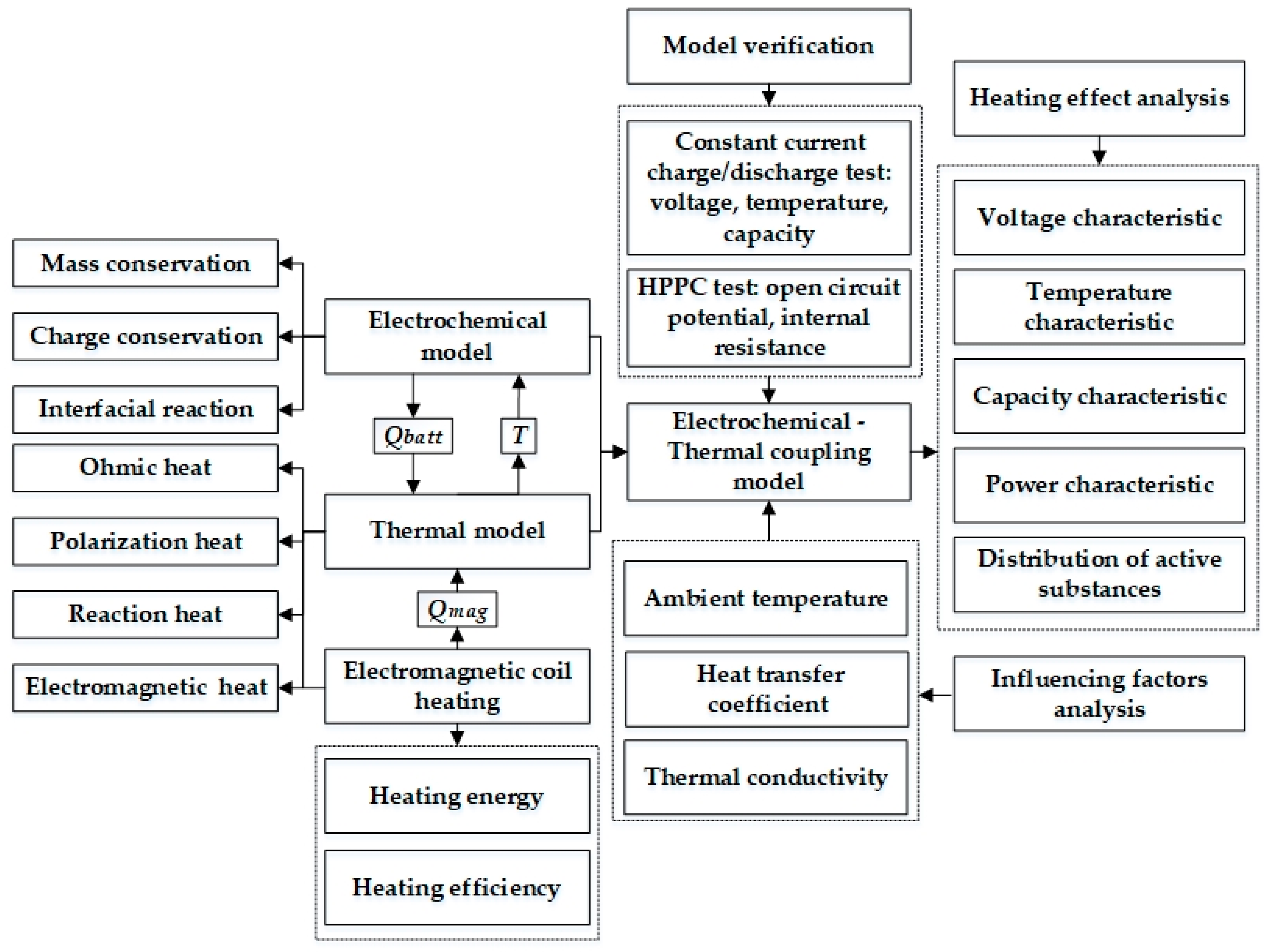
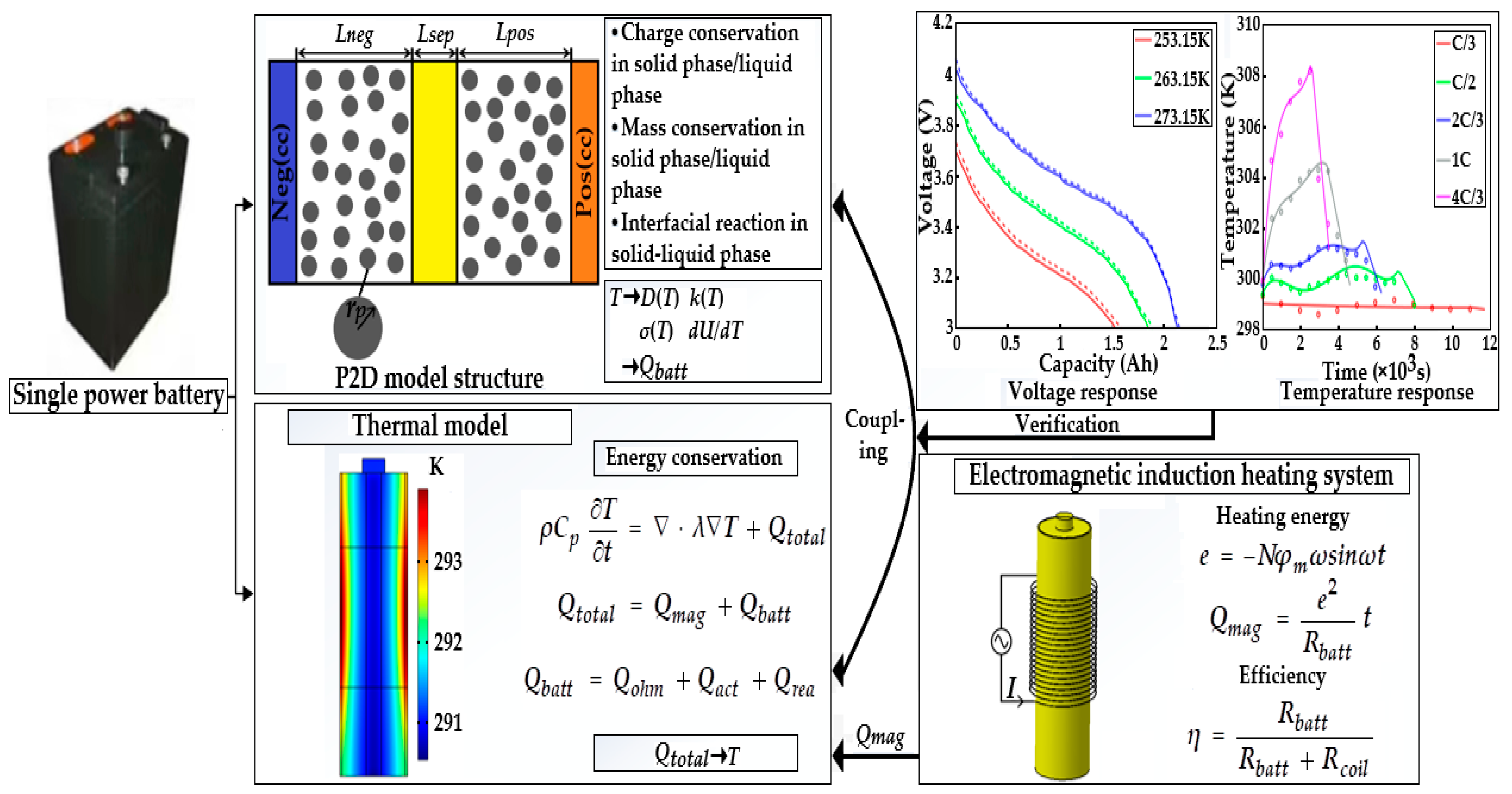
In this work, in order to reach a tradeoff between heating time, temperature distribution, and LiB durability, an extremely fast electromagnetic induction heating technology for low temperatures based on the ETCM is put forward for the first time, which can heat LiBs in a short time through the thermal effect caused by the induced current passing through the interior of the LiB. The eddy current can be induced using the varying magnetic flow inside the LiB that is generated by the alternating current via the copper coil. Figure 1 presents the framework for this study, and a list and definitions of the nomenclature used in this paper are provided in the Nomenclature section. Firstly, the layout of the components of the heating system and the heating principle are explained in detail through a schematic diagram, theoretical analysis, and equivalent circuit in an effort to deduce the energy and efficiency of the system. Secondly, based on the P2D model and the electromagnetic induction heating principle, we established an ETCM in which the electromagnetic heat is embedded into the lumped thermal generation model coupled with the P2D model in order to affect the temperature-sensitive coefficients. The simulation results were mostly consistent with the charging, discharging, and HPPC experimental data under various temperature conditions, indicating that the high-precision model can be used to develop heating schemes. Thirdly, the simulation showed that the electromagnetic induction heating technology with a high heating velocity can warm up the LiB from 243.15 K to 293.15 K within 352 s, with an instantaneous temperature increase rate of 0.263 K/s and a maximum temperature difference inside the LiB of only 3.38 K. Further, we explored the influence of the heat transfer environment on temperature rise, including ambient temperature and the surface heat transfer coefficient, and the effect of the thermal conductivity of the LiB material on the temperature stability inside the LiB. Finally, according to the simulated results of the cycle capacity, HPPC test, and cyclable lithium inside the active particle on the surface of the negative electrode, compared with the normal charge–discharge cycles at room temperature, the fading of the LiB capacity after heating with the method for 60 continuous cycles was negligible, indicating that the method had no detrimental effect on LiB aging, and either the internal resistance or lithium concentration inside the particle had a significant improvement; thus, the LiB’s usable energy and power can be promoted qualitatively after the heating, achieving an excellent balance between work ability and health of the battery. Therefore, this ultrafast electromagnetic induction heating technology has the potential to be a feasible method for warming up LiBs in extremely cold climates.
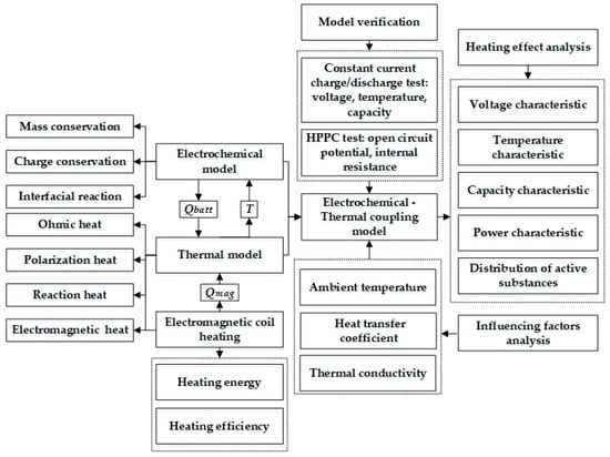
Figure 1.
The framework of the paper’s ideas.
2. The Principle of Electromagnetic Induction Heating
2.1. System Structure
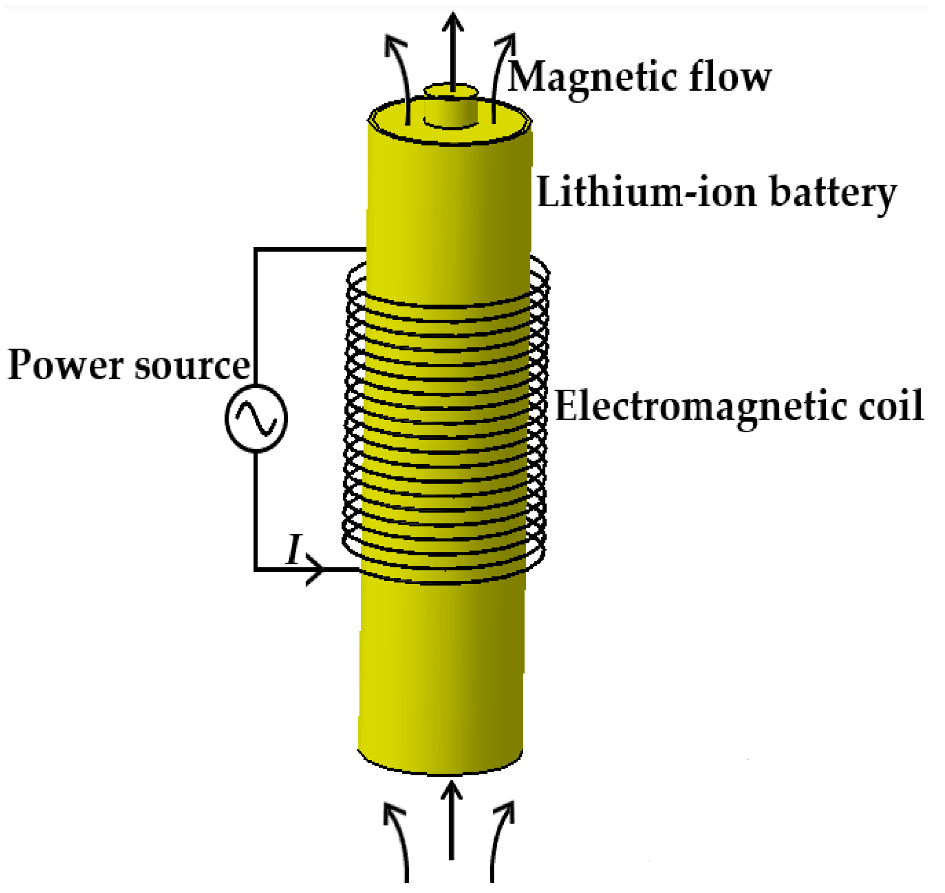
Figure 2 shows the schematic diagram of applying electromagnetic induction to heating LiBs in cold weather; the copper coils, the component generating the alternating magnetic field, are connected to an alternating power source through wires and are uniformly arranged in the middle area of the LiB.
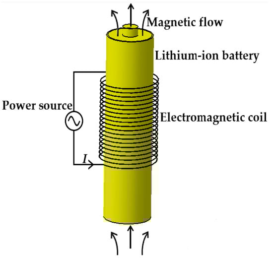
Figure 2.
The schematic of the electromagnetic induction heating system.
The induction heating technology was developed based on Faraday’s law of electromagnetic induction with the advantages of no pollution generation, fast heat production, and high heating efficiency. When the wires are subjected to an AC, an alternating magnetic field is generated around the copper coil, giving rise to a variation in the magnetic flow inside the LiB in the magnetic field. Due to the electromagnetic induction phenomenon, the LiB in the closed loop cuts the magnetic induction line to produce an induced electromotive force, which can drive the free electrons to generate directional motion that creates an induction current and converts electrical energy into Joule heat through the resistance effect of a conductor in order to make the LiB’s temperature rise.
2.2. Theoretical Analysis
Lenz’s law indicates that the magnetic flow generated by an induced current always tries to hinder changes to the original magnetic flow, so the variation in the former is in the opposite direction to the latter’s, and both the directions of the former and the induced electromotive force conform to the right-hand screw rule. The induced electromotive force is defined as:
where e is the induced electromotive force, and dφ/dt is the varying rate of the magnetic flow.
When the changing magnetic flow is in accord with a sinusoidal waveform, then
where φm is the amplitude of the magnetic flow, and ω is the angular velocity of the magnetic flow variation.
Thus,
The effective value of the induced electromotive force is
where f is the changing frequency of the magnetic flow and equals ω/2π.
Owing to the electrical conductivity of the LiB itself, the electrons inside the LiB generate directional movement under the function of the induced electromotive force, which can generate a reverse eddy current in the form of a closed loop current combined with the resistance effect of the LiB to produce the Joule heat for increasing the LiB temperature. The heating energy can be expressed as:
where Qmag is the heat generated by electromagnetic induction, Rbatt is the LiB resistance, and t is the heating time.
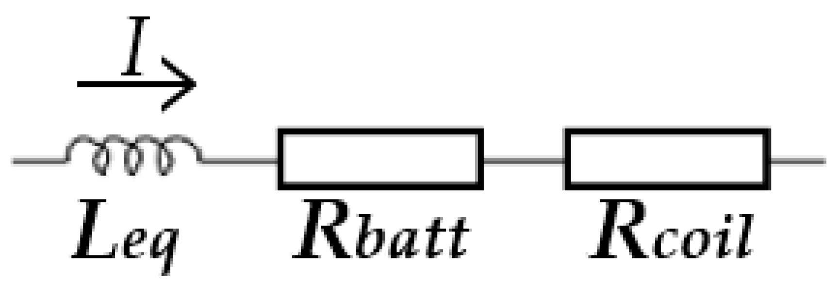
According to the equivalent electrical circuit presented in Figure 3 [39], we can calculate the heating efficiency during the ultrafast heating process.

Figure 3.
The equivalent electrical circuit of the electromagnetic induction heating system.
The total impedance can be described as:
where Z is the total equivalent impedance of the system, Rcoil is the copper coil resistance, and Leq is the equivalent inductor in series.
According to the heating frequency, the LiB material’s properties, other parameters in this study, and the skin effect, as the skin depth of the copper is much higher than the strand radius of the coil, we assume that the free electrons in the coil section have an even distribution; consequently, Rcoil can be expressed as:
where ρcoil is the coil resistivity, l is the length of the coil, and S is the cross-sectional area of the coil.
The electromagnetic induction heating efficiency can be calculated as:
where Pbatt is the active power transmitted to the LiB, Ptotal is the total active power transmitted to the copper coil, and I is the SAC acting on the copper coil.
3. Model Development
3.1. Model Overview
Figure 4 presents the framework of the ETCM composed of an electrochemical model, thermal model, and electromagnetic induction heating module, which was validated against the experimental results under various ambient temperature conditions.
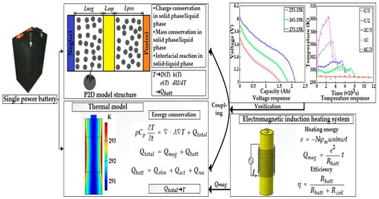
Figure 4.
The framework of the ETCM.
3.2. Electrochemical Model
The electrochemical model for the LiB with a negative-electrode-separator-positive- electrode structure adopted the P2D model based on the theory of porous electrodes; the governing equations depicting the Li+ diffusion in the solid particles, Li+ mass transfer in the liquid phase, and interfacial electrochemical reactions on the surface of the particles are as follows:
- (1)
- Mass conservation equations: Supposing that the reaction particle at each point on the spherical surface with a certain radius has the same concentration, then the mass balance in the process of Li+ extraction–insertion inside the spherical particles of solid-phase active materials is in line with Fick’s second law under the form of a polar coordinate system.
The boundary conditions are
where r is the distance from the spherical particle center and j is the local reaction current density.
Combining the species flux density expression based on the theory of concentrated solutions with the material balance in the electrolyte of porous electrodes, as was shown in [16], the change in the Li+ concentration can be written as:
where i2 is the current density in the electrolyte and Ce is the Li+ concentration in the electrolyte.
Considering the impact of the tortuosity of porous electrodes on diffusivity,
where Brugg is the Bruggman coefficient, commonly set as 1.5.
The boundary conditions are
where L is the total length of the LiB and equals Lneg + Lsep + Lpos.
- (2)
- Charge conservation equations: The Li+ potentials in both the electrode and the electrolyte follow Ohm’s law, in which the potential distribution in the solid phase is written as:
Considering the impact of porosity on electrical conductivity,
The boundary conditions are
where iapp is the applied current density.
The charge transfer in the electrolyte is realized by electromigration and diffusion, ignoring the action of convection, which can be given by:
where Φe is the potential in the electrolyte.
The boundary conditions are
- (3)
- Electrochemical reaction kinetics: The net velocity of the charge transfer reaction that occurs in the solid–liquid-phase interface can be described by the Butler–Volmer equation.
The LiB terminal voltage at each moment can be described by the voltage difference between both ends of the solid phase.
3.3. Thermal Model
The LiB temperature calculated in the thermal model has an important impact on the parameters in the electrochemical model, reflecting the reaction process and mechanism at each temperature interval. Therefore, it is necessary to ensure the computational accuracy of the thermal model. According to [9], the heating generation rate inside the 18,650 LiBs is considered to be consistent, and hence, the thermal conservation equation can be defined by the lumped parameter method in a cylindrical coordinate system.
where Qtotal is the total heat, which is produced in the course of electromagnetic induction heating, comprising the heat generated by electromagnetic induction and electrochemical reactions.
The boundary condition based on Newton’s law of cooling is
where Ta is the ambient temperature.
As a result, the total heat production can be written as:
where Qbatt is the heat produced by electrochemical reactions, consisting of ohmic heat, polarization heat, and reaction heat, which represent the action of ohmic potential, electrode polarization, and enthalpy change in the process of the reaction, respectively.
Then,
where Qohm, Qact, and Qrea are the ohmic heat, polarization heat, and reaction heat, respectively.
3.4. Electrochemical–Thermal Coupling Characteristics
Some of the parameters in the electrochemical model have high-temperature sensitivity such as solid and liquid-phase diffusivity, liquid-phase electrical conductivity, entropy heat coefficients of the electrodes, exchange current density, and others, among which the variations in solid-phase diffusivity and reaction rate constant correspond to the Arrhenius equation.
where Ψ is the temperature-sensitive parameter, Ψref is the value of the parameter at Tref, and Ea is the reaction activation energy.
Conversely, according to 3.3, some temperature-sensitive coefficients and other parameters in the electrochemical model, including the specific surface area of the solid-phase particle, Li+ concentration in the electrolyte, solid- and liquid-phase potentials, the resistance of the SEI film, etc., are directly related to the total heat production together with the electromagnetic induction heat. Therefore, taking the heat generated by electrochemical reactions as the thermal model input and the LiB temperature as the output, and using the induction heat to transfer heat in the solids in the form of a heat source of an active material, the electrochemical–thermal two-way coupling effect can be carried out by considering the temperature dependence of parameters in the electrochemical model and concurrently solving the electrochemical and thermal models.
3.5. Model Validation
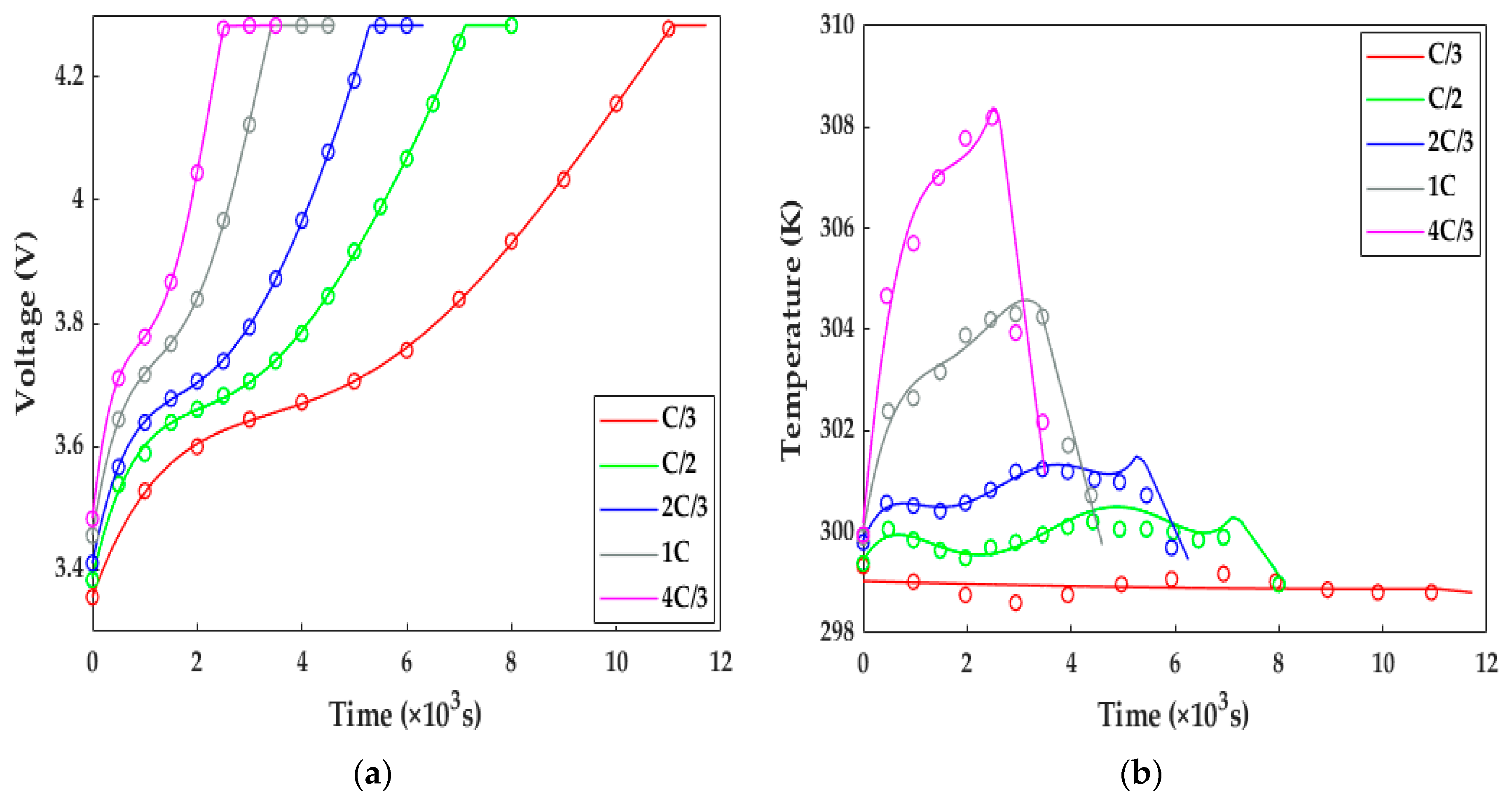
In this study, the ETCM was validated against the experimental data of the HPPC test and constant current discharge and charge under the conditions of various ambient temperatures. Figure 5 compares the simulated results with the constant current charging experimental data originating from [13]. Under the variant charging rates at 298.15 K, we can observe from Figure 5 that, along with the increasing charge rate at a normal temperature, not only was the charging time shortened from 11,000 s for the C/3 rate to 2500 s for 4C/3, resulting in the declining charge capacity owing to the intensive ohmic and electrochemical polarization, but the extent of the temperature rise and drop during and after the charging showed a strongly increasing growth. It can be noted from Figure 5 that the numerical terminal voltage and temperature of the LiB matched well with the test results; the average voltage and temperature errors were less than 4.5 mv and 0.5 K, respectively; thus, the ETCM can obtain an excellent charging response at room temperature.
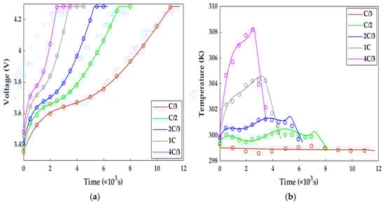
Figure 5.
The model validation under the charging tests with different rates at 298.15 K. Solid line = model results, circles = test results. (a) Voltage response; (b) temperature response.
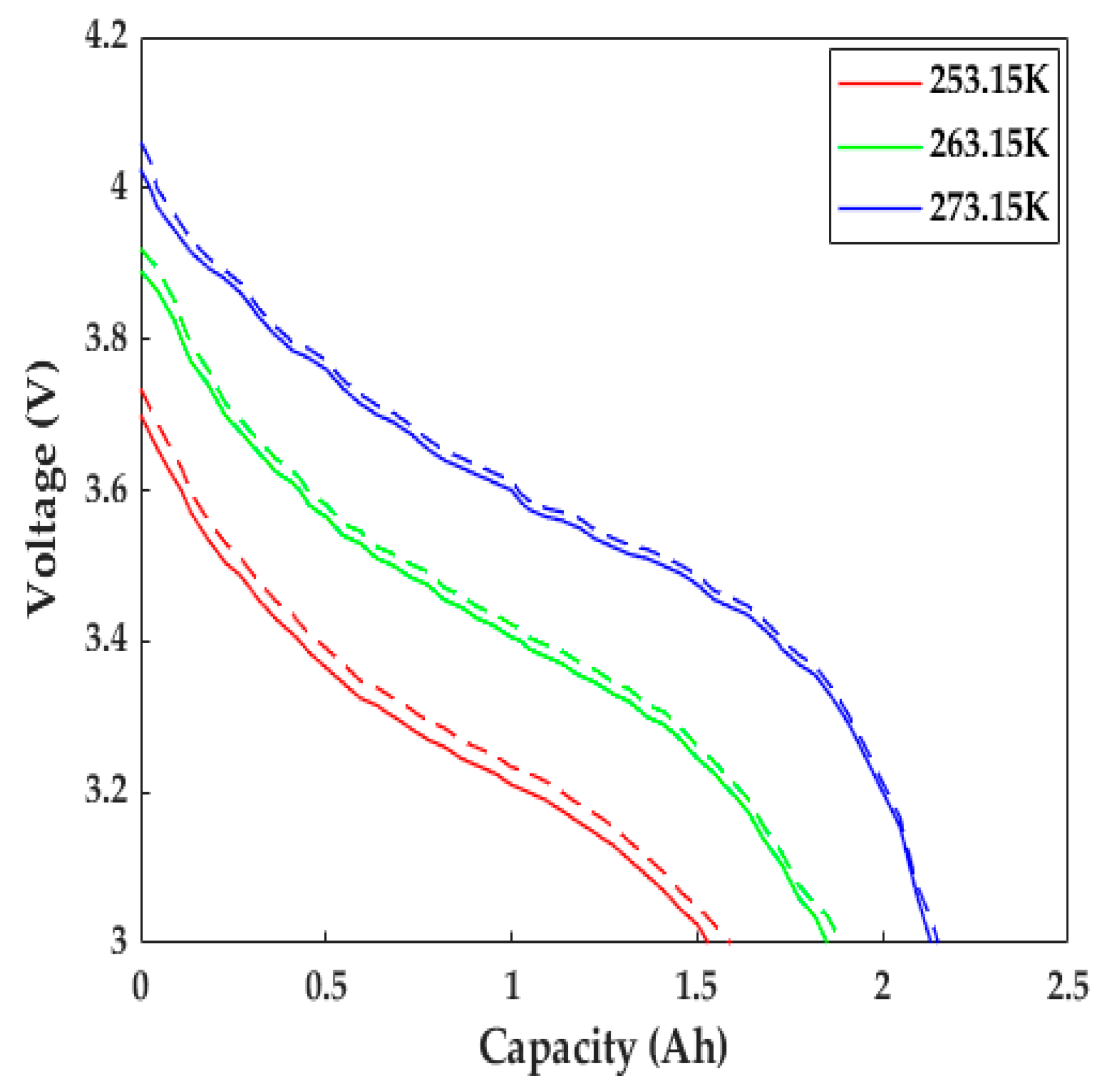
The LiB performance in cold weather can be explored using the proposed ETCM. The constant current discharging data with a 1C rate at different low temperatures from [23] and its corresponding numerical results are presented in Figure 6. Due to the slow Li+ diffusion, low-electrolyte electrical conductivity, and other reasons, the increase in LiB impedance led to the expansion of the partial voltage of the internal resistance; thus, the LiB voltage declined rapidly as the temperature decreased, causing a decrease in the time to reach the cutoff voltage, with the degree presenting an uptrend with the decrease in temperature. The capacity at 253.15 K decreased by nearly 40% compared with the rated capacity (only 1.53 Ah). We can see that the simulated voltage profiles agreed well with the experimental data: the computational capacities were 0.06, 0.04, and 0.015 Ah more than the test ones at 253.15, 263.15, and 273.15 K, respectively, which mainly resulted from the inadequate consideration for the effects of SEI film growth and lithium plating/stripping, since the SEI film growth rate was defined as a constant, and the contact resistance between the electrode material and tab/collector, poor conductive agent, and adhesive with the aging of the LiB were not taken into account in the study.
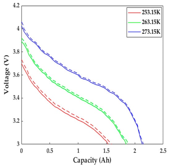
Figure 6.
Comparison of the discharging behaviors with a 1C rate at various low temperatures. Solid line = experimental results, dashed line = model results.
In addition to this, the responses of the internal resistance and OCP based on the HPPC test carried out by [23] are depicted in Figure 7. The trends and reasons for the increase in internal resistance and the decrease in OCP are in accordance with the voltage evolution mentioned in the preceding paragraph. The numerical internal resistance and OCP have similar behaviors to those of the experimental data at different low temperatures. The internal resistance differences between the simulated and experimental results were 15.2, 10.1, and 5.4 mΩ, while the OCP differences were 24, 18.2, and 12.2 mV at 253.15, 263.15, and 273.15 K, respectively. The reasons for these differences are just like the ones mentioned above. Despite these gaps, the ETCM developed in the study still can produce a reasonable prediction in terms of electrochemistry and heat; in general, the highly accurate ETCM has the potential to be applied as an effective tool for the development of heating schemes without any tests and provides a theoretical guidance for experiments.
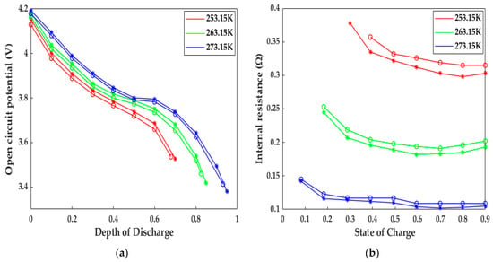
Figure 7.
The model validation under the HPPC tests at various low temperatures. Circles = test results, stars = model results. (a) OCP response; (b) internal resistance response.
4. Simulation
4.1. Research Object
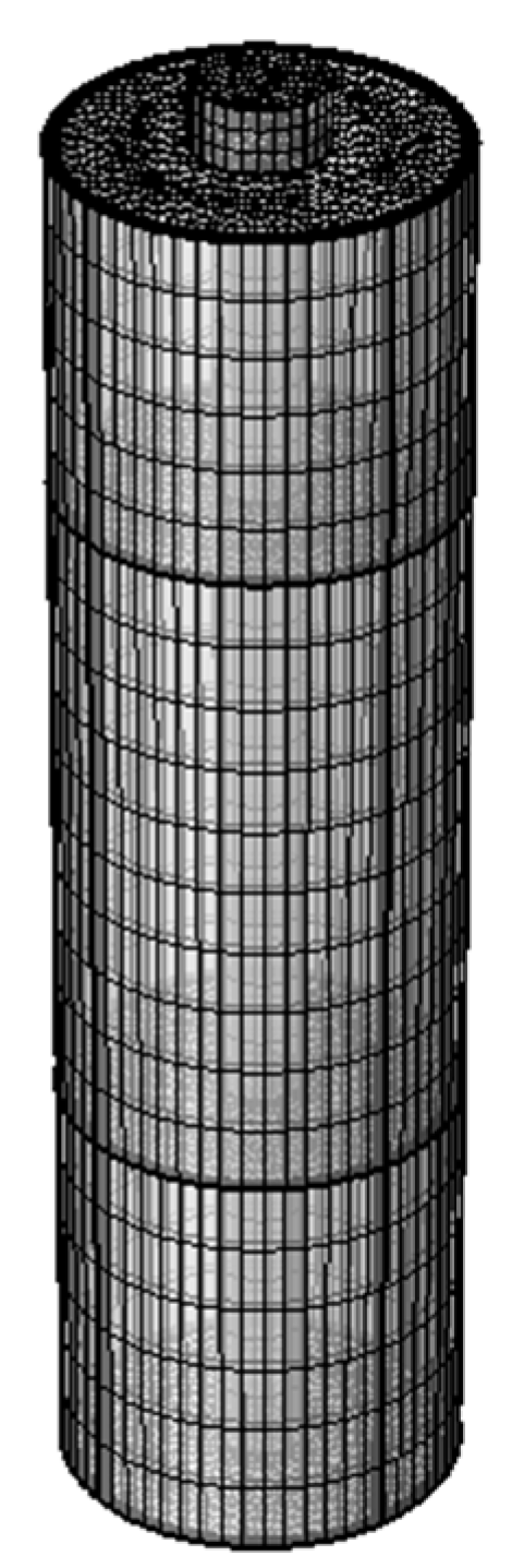
A commercial 18,650 battery was utilized as the object of this study; its materials and specifications are listed in Table 1. The ETCM with a 3D geometric structure to characterize the effect of the electromagnetic induction heating system on the electrical and thermal behaviors of LiBs was developed in COMSOL Multiphysics 6.0. The ETCM parameters including the induction copper coil specs as well as the model parameters regarding electrochemistry and heat are shown in Table 2, and the LIB mesh based on the free triangular structure, established using sweeping and mapping, is exhibited in Figure 8. Moreover, in this study, the magnetic field model and the model of the lithium battery and heat transfer in solids need to be solved in the frequency and time domain, respectively.

Table 1.
The materials and specifications of the research object.
Table 2.
The induction copper coil specs and the parameters applied in the ETCM.

Figure 8.
Sketch of the divided LiB mesh in COMSOL.
4.2. Heating Simulation
The ambient temperature and initial state of charge (SOC) were separately set at 243.15 K and 50%, respectively. Unless otherwise specified, the heating process ends when the temperature of the cell reaches 293.15 K. The LiB temperature mentioned here refers to the average temperature of the battery shell surface. In order to investigate the impact of the heating method on the consistency of the LiB temperature, we established a rapid YZ cut plane in the data set of the results to observe the temperature distribution inside the LiB during the heating process. Additionally, according to the equations in the thermal model, the external heat transfer environment has a direct influence on temperature rise, so some influencing factors regarding the surface transfer heat, such as h and Tamb, were modified to allow us to analyze the effect of external environment on temperature rise. By comparing the effects of heat generation inside the LiB under the different thermal conductivities of the active material, the impact of the material’s properties on the uniformity of the LiB temperature after heating can be investigated to determine if the heating scheme can accelerate LiB aging.
4.3. Electrochemical and Thermal Properties Simulation
To determine the extent to which the ultrafast electromagnetic induction heating system improves the LiB’s poor performance in cold weather, the fully charged LiB was discharged to 3.0 V with a constant current at a 1C rate during the heating process, and the discharge time/capacity was measured to evaluate the enhancement of energy release. After the heating, the LiB with 100% SOC was analyzed using the HPPC test simulation (see Figure 9 for procedure) to obtain the charge and discharge pulse power and internal resistance, which can reflect the LiB’s dynamic pulse characteristics at different intervals of SOC through the discharge and feedback pulse. We compared the distribution and amount of the cyclable lithium inside the active particle at the half length of the negative electrode after the constant current discharge at 243.15 K until the terminal voltage decreased to 3.0 V and after the end of heating the LiB. The Li+ concentration inside the particle can be seen in the form of cloud charts to study the recovery of the work potential and the influence of the heating method on the interior of the LiB. Finally, the rapid heating from 243.15 to 293.15 K was repeated 60 times, and the LiB discharge capacity at a 1C rate was calibrated every 5 heating cycles. Starting with 100% SOC, we can observe the degradation of the cycle capacity to verify the impact of the heating method on the LiB durability compared to normal charge–discharge cycle capacity at room temperature.
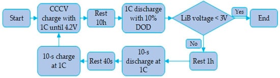
Figure 9.
HPPC simulation flow path.
5. Results and Discussion
5.1. Research on Heating Effect
Figure 10 shows the temperature characteristics of the LiB in the heating process with a copper excitation current of 8 A and 50 Hz. The LiB was placed at 243.15 K and heated to 293.15 K within 352 s; the maximum instantaneous temperature increase rate reached 0.263 K/s, and the average temperature increase rates were enhanced by 4.21 and 1.28 times under the conditions that the excitation current amplitudes were almost equal and higher than the one adopted in this paper compared to the SAC heating method proposed in [9] and [11], respectively. Although the effect of the temperature increase in this study cannot be as good as the 1 K/s for ACB [37] and 0.181 K/s for intermittent electric-triggered heating technology [17], the induction heating method avoids the safety and cycle lifespan degradations caused by the instantaneous short circuit induced by large current self-discharge in a short time. Meanwhile, the heating system in this study can maintain a relatively excellent temperature increase velocity. We can see from Figure 10c that the heating method can achieve a uniform temperature distribution inside the LiB, in which the temperature difference at the end of the heating was only 3.38 K, probably resulting from the inadequate heat transfer caused by the low thermal conductivity of the LiB materials (this will be discussed in detail in Section 5.4.2). Thus, the heating method can obtain a small temperature gradient and reduce the degradation of the LiB materials, thereby reducing the local heat-induced aging effect due to temperature inconsistencies in the interior of the LiB.
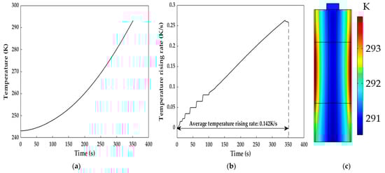
Figure 10.
Diagram of the temperature increase after the heating. (a) Profile of the temperature increase during the heating; (b) temperature increase rate during the heating; (c) temperature distribution inside the LiB at the end of the heating.
Figure 11 presents the voltage evolution of the LiB discharged with a constant current at a 1C rate during the heating process. The discharge capacity/time of the LiB was 1.39 times better than that at 243.15 K without any heating measures; it was 0.11 Ah below the discharge capacity in normal weather, even compared with that at 293.15 K. The 1C discharge energies, calculated by integrating the voltage profiles with respect to discharge time, were 211.07, 219.91, and 65.34 kJ·kg−1 for the cell that was heated throughout the discharging process and discharged at 293.15 K and 243.15 K, respectively, indicating that the high LiB terminal voltage shown in the process of discharging protects the electrode materials against potential degradation, which can substantially increase the discharging ability. Thus, the qualitative improvement in the working capacity provides much more usable energy, allowing EVs to obtain a sufficient cruising range to ensure operation in frigid climates.
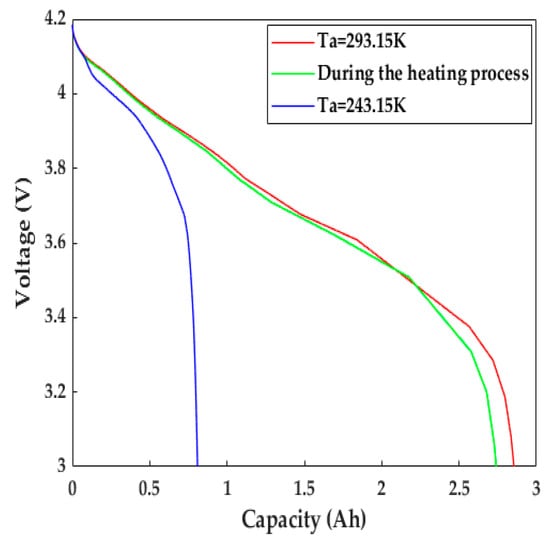
Figure 11.
The evolution of terminal voltage during the heating process.
Figure 12 shows the evolution of the Li+ concentration distribution inside the active particle on the surface of the negative electrode before and after the heating. The Li+ concentration had an even distribution inside the particle before the constant-current discharge, it started to gradually extract from the particle surface as the discharge progressed, causing a descending Li+ concentration inside the particle and an obvious Li+ concentration gradient to form from 60% of the particle radius to particle surface without the application of the heating system until the end of the discharge. The Li+ concentration showed a significant improvement, and the concentration gradient existed on the surface of the particle after the above-mentioned LiB was heated to 293.15 K following the discharge, as presented in Figure 12c. It is clear from the above phenomenon that the heating method can not only effectively recover the work potential but also cause less damage to the interior of the LiB.
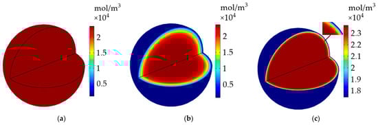
Figure 12.
The evolution of Li+ concentration inside the active particle on the surface of the negative electrode. (a) Before the discharge; (b) after the discharge without heating; (c) after the heating following the discharge.
5.2. Analysis of HPPC Simulated Results
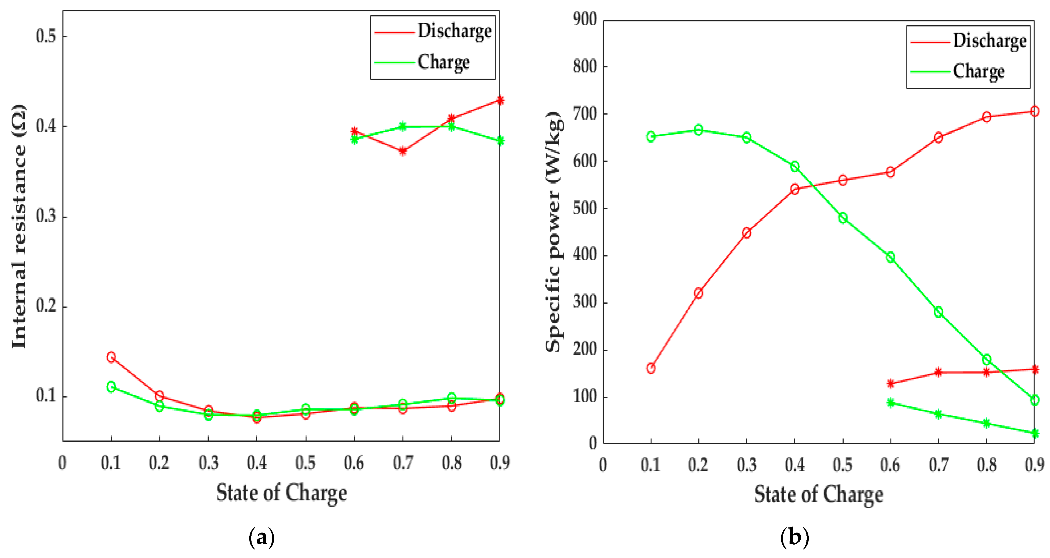
In this study, the 10 s-HPPC simulation was performed to reflect the LiB pulse dynamic behaviors, as shown in Figure 13. If the LiB did not experience any heating action, the depth of discharge (DOD) only reached 40% at 243.15 K, and the average internal resistance of the LiB was approximately three-fold higher compared to that after being heated to 293.15 K; thus, the electromagnetic induction heating system can decrease the internal resistance to that at room temperature and then improve the poor discharge ability and lifetime of LiB in cold climates. Expect for the discharge energy, the specific power is another index that reflects the working capacity of a LiB. It can be observed from Figure 13b that the LiB discharged power up to 577.49 and 694.39 W·kg−1 at 60% and 80% SOC after the heating, respectively, which is 3.54 times higher than that at 243.15 K. Similarly, the improvement in charge power due to the heating method also reached a satisfactory level, with an increase from 44.19 to 179.71 W·kg−1 for 80% SOC and 88.13 to 396.91 W·kg−1 for 60% SOC, which suggests that the LiB after heating with our method has a strong regeneration capacity to increase the charging velocity and fully regenerate the braking energy, thereby enhancing the availability of stored energy. The high power improves the poor climbing and accelerating ability at low temperatures and provides more possibilities for the application of EVs in extremely cold areas, as well as electric ships, unmanned aerial vehicles, etc.
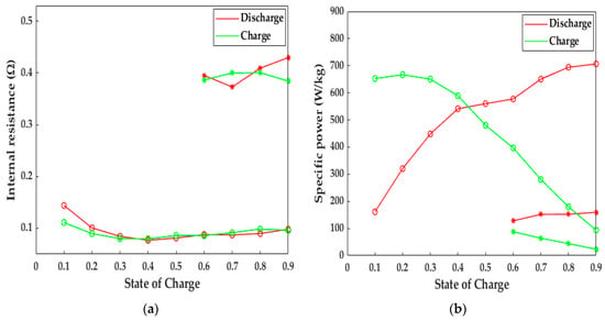
Figure 13.
Computational results for 10-s HPPC simulation. Circles = after the heating, stars = no heating. (a) The change in internal resistance with SOC; (b) the change in specific power with SOC.
5.3. The Impact of the Heating Method on Battery Aging
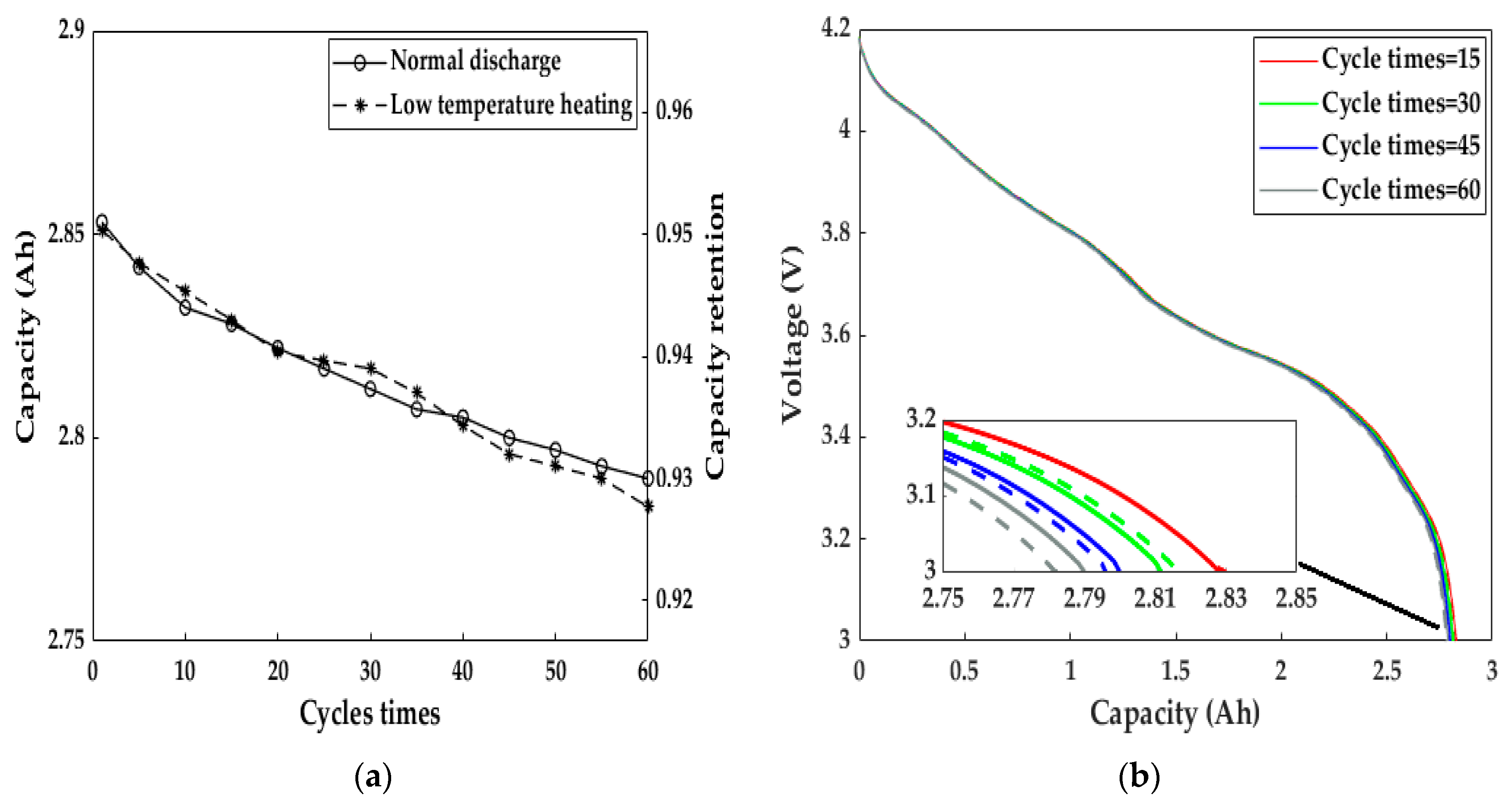
We studied the effect of the electromagnetic induction heating system on LiB aging by measuring the cycle capacity characteristics after continuous heating for 60 cycles (Figure 14). After heating for 60 consecutive cycles, the discharge capacity retention at a 1C rate reached 92.77%, and the capacity difference before and after the 60 cycles of heating was only 0.068 Ah. Meanwhile, the LiB had a tiny discrepancy in the fading velocity compared to the normal cycle capacity at 293.15 K, and the LiB voltage–capacity curves were almost the same, implying that the heating method did not accelerate LiB aging due to the minimal capacity deterioration. As a result, both the LiB’s work ability and health remained at a satisfactory level using the heating scheme proposed by this paper, allowing users to have a better driving experience in cold weather than before, similar to that at room temperature.
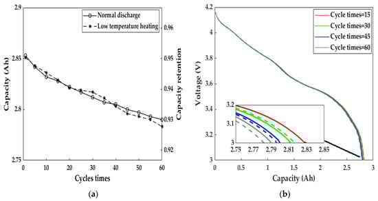
Figure 14.
The cycle capacity calibration results after every five consecutive heating cycles and under normal charge–discharge cycles at 293.15 K. (a) Discharge capacity and its retention; (b) voltage profiles after heating cycles 15, 30, 45, and 60. Solid line = normal cycle at 293.15 K, dashed line = heating cycle.
5.4. Analysis of Influencing Factors
5.4.1. External Environmental Factors
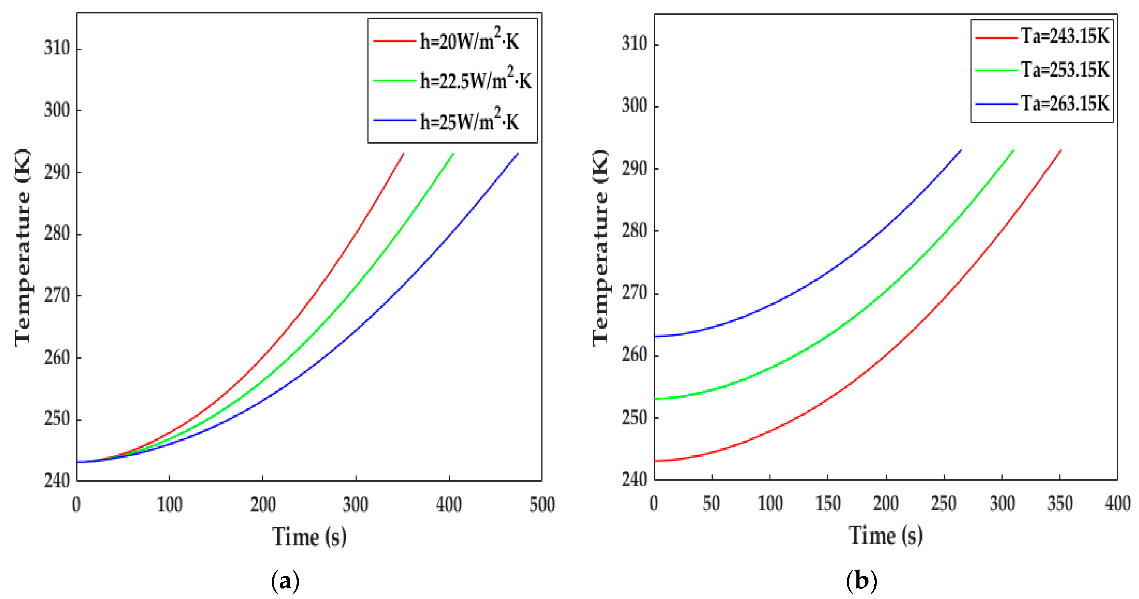
In this study, h and Tamb were selected to investigate the influence of the heat transfer environment on the increase in temperature. As can be observed from Figure 15a, when h was set at 22.5 and 25 W·m−2·K−1, the LiB temperature reached 293.15 K within 406 and 474 s, respectively. We can see from Equation (28) that the higher h, the higher the heat dissipation, and the average rate of temperature decrease presented an increasing trend along with the increase in h compared with Figure 10a, indicating that good thermal insulation is essential to increasing heat production and reducing heating time. Figure 15b plots the temperature rise at different ambient temperatures. The LiB was warmed up to 293.15 K within 312 s for 253.15 K and 266 s for 263.15 K, so the differences between the different initial temperatures became smaller and smaller as the heating progressed.
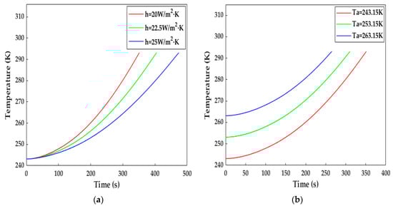
Figure 15.
The impact of external environmental factors on the increase in temperature. (a) With different surface heat transfer coefficients; (b) at different ambient temperatures.
5.4.2. Material Properties
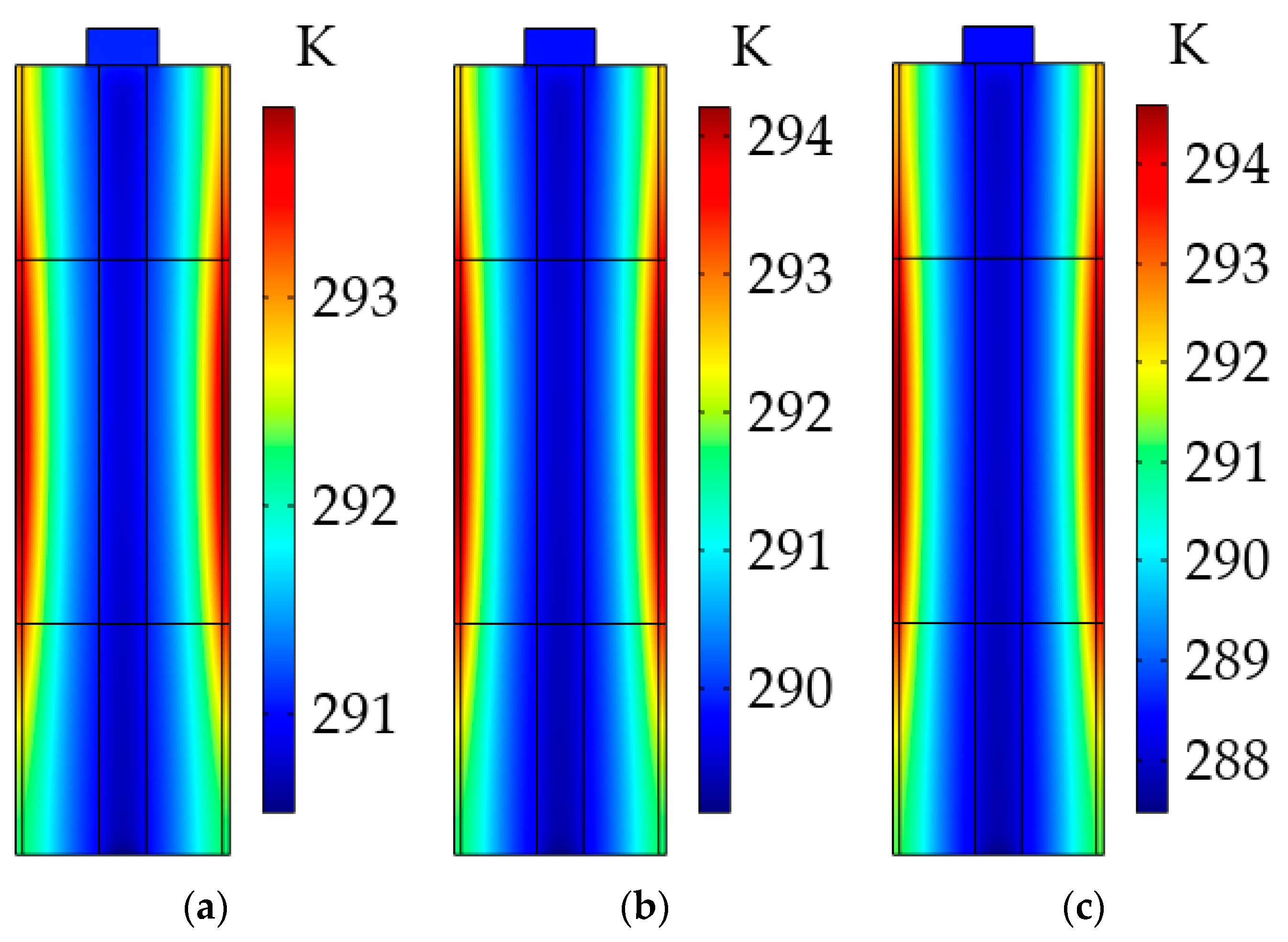
As stated above, the uneven temperature distribution could be due to the low thermal conductivity of the LiB materials, so we explored the impact of the radial thermal conductivity of the active material on the LiB temperature gradient. As can be seen from Figure 16, the maximum temperature differences inside the LiB after the heating were 5.1 and 7.13 K at 0.8 W·m−1·K−1 and 0.7 W·m−1·K−1, respectively. For the low radial thermal conductivity, the inadequate heat transfer can bring about a large temperature gradient from the battery shell to the mandrel, and this heterogeneous temperature distribution inside the LiB is expected to cause the degradation of LiB material, hence accelerating the LiB aging and irreversibly reducing the LiB’s cycle lifetime. For the high thermal conductivity, the opposite results were observed. Thus, to avoid affecting the work capacity of the LiB, using a better battery material with a sufficiently high thermal conductivity is an effective way to improve the LiB temperature consistency during the heating process.

Figure 16.
Temperature distribution inside the LiB at different radial thermal conductivities of active material after the heating. (a) At 0.9 W·m−1·K−1; (b) at 0.8 W·m−1·K−1; (c) at 0.7 W·m−1·K−1.
6. Conclusions
In this paper, we aimed to improve the poor performance of LiBs at low temperatures. A method was proposed to rapidly heat LiBs in cold weather by applying electromotive induction heating technology, with the heat originating from the Joule heat produced through the interaction between the eddy current induced by an electromotive force and battery internal resistance effect, which is realized by a copper coil that is regularly fixed in the middle of the LiB with 201 turns and a cross-sectional area of 1 × 10⁻⁶ m2.
The ETCM based on the theory of porous electrodes, lumped heat generation method, and electromagnetic heat was developed in COMSOL Multiphysics 6.0 to investigate the LiB heating effect and the influence of parameters on the increase in LiB temperature. Both the discharging and charging responses showed good agreement with the experimental results at different temperatures, and the error in temperature, capacity, and internal resistance can be controlled to an extremely low level, indicating that the model can predict the LiB’s electrochemical and thermal behaviors with high precision and hence can be applied as a development tool to evaluate heating effect without the need for experiments.
When the copper coil was subjected to a SAC of 8 A and 50 Hz, the LiB can be heated from 243.15 K to 293.15 K within 352 s, with a maximum instantaneous temperature increase rate of 0.263 K/s, and the temperature difference inside the LiB was only 3.38 K, thereby simultaneously obtaining a high heat generation rate and uniform temperature distribution. After heating, the Li+ concentration gradient inside the active particle on the surface of the negative electrode only existed on the particle surface. Meanwhile, the Li+ concentration showed an obvious increase; thus, the heating method is beneficial to the recovery of work potential and has almost no detrimental effect on the interior of the particle. The capacity calibration and HPPC simulation results showed that the internal resistance was nearly three times lower than that without heating so that the usable energy and specific power achieved a remarkable improvement through the heating scheme, enhancing the LiB’s work capability at low temperatures. It is noteworthy that the capacity retention during the consecutive heating cycles was almost the same as that at room temperature, and no apparent capacity deterioration was observed at the end of the 60 cycles of repetitive heating. Hence, the method does not damage the LiB life, so the electromagnetic induction heating technology can achieve a good tradeoff between a good temperature increase effect, work capability, and LiB health compared to other heating methods. The average temperature increase rate of the proposed heating system is lower than that of the ACB structure and electric trigger heating method proposed in [37] and [17], respectively, but better than that of the SAC heating method developed by Zhang et al. [9] and Ruan et al. [11] when the excitation current amplitude was almost same or higher than the one applied in this work. Meanwhile, the electromagnetic induction heating system can avoid the safety and life reduction induced by an instantaneous short circuit, and it has no apparent impact on the LiB’s specific power, energy, and durability compared with the numerical results at room temperature.
Therefore, the contributions of the paper can be reflected in two aspects. On the one hand, the impact of the electromagnetic induction heating system on the LiB temperature increase, thermal distribution, life reduction, etc., can be explored using the proposed high-precision ETCM, which could reduce the development time and cost. On the other hand, the heating method proposed in this work can rapidly warm LiBs up to a friendly temperature in cold weather with almost no influence on the LiB’s safety and durability, which has considerable potential to improve LiBs’ work capability and enhance the practicality of EVs in extreme climates. Moreover, the optimization of the transfer heat environment and the material’s thermal conductivity could also promote the increase in LiB temperature.
Although the presented work aimed to improve the poor electrochemical and thermal performances of LiBs at low temperatures by applying electromagnetic induction heating technology, the influence of the heating system parameters, especially those of the copper coil on the heating effect, is still unknown, and this development of the heating strategy is not yet completed, which restricts the engineering applications of this heating system. Thus, future efforts will focus on the excitation current parameters acting on the copper induction coil, researching the influence of the amplitude and frequency of the copper coil excitation current on the heating effect. The variation in heating time with the excitation current parameters will be presented in the form of heating time maps so as to recognize the dominant factor affecting the heating process. Long-term heating tests such as 150 or 200 cycles will be conducted in order to clearly characterize the effect of the proposed heating system on the LiB’s lifetime. By considering the heating time, temperature distribution, state of health, work capacity. and other technical specifications in different ranges of excitation current amplitudes and frequencies, our research team will design a reasonable heating strategy to improve the practicability of the heating system while minimizing the security risks.
Author Contributions
Conceptualization, B.W. and M.Y.; methodology, B.W.; software, B.W.; validation, B.W.; formal analysis, M.Y.; investigation, B.W. and M.Y.; resources, M.Y.; data curation, B.W.; writing—original draft preparation, B.W.; writing—review and editing, B.W. and M.Y.; visualization, B.W.; supervision, B.W.; project administration, M.Y. All authors have read and agreed to the published version of the manuscript.
Funding
This research received no external funding.
Data Availability Statement
The data presented in this study are available on request from the corresponding author.
Conflicts of Interest
The authors declare no conflict of interest.
Nomenclature
The nomenclatures used in this paper are shown below:
| Nomenclature | |||
| as | specific superficial area (m−1) | RSEI | SEI film resistance (Ω) |
| Brugg | Bruggman coefficient | Rs | radius of the particles (m) |
| C | Li+ concentration (mol·m−3) | r | distance from the spherical center (m) |
| Cp | heat capacity at constant pressure (J·kg−1·K−1) | S | cross-sectional area of the copper coil (m2) |
| D | diffusivity (m2·s−1) | T | temperature (K) |
| dU/dT | entropy heat coefficient (V·K−1) | Ta | ambient temperature (K) |
| E | effective value of induced electromotive force (V) | t | time (s) |
| Ea | reaction activation energy (j·mol−1) | t+0 | transference number |
| e | induced electromotive force (V) | U | equilibrium potential of the electrode material (V) |
| F | Faraday’s constant (C·mol−1) | V | battery terminal voltage (V) |
| f | changing frequency of the magnetic flow (Hz) | Z | total equivalent impedance of the heating system (Ω) |
| h | surface heat transfer coefficient (W·m−2·K−1) | z+ | charge number |
| I | the SAC acting on the copper coil (A) | Greek | |
| i | current density (A·m−2) | αa, αc | charge transfer coefficient |
| iapp | applied current density (A·m−2) | ε | volume fraction |
| i0 | exchange current density (A·m−2) | η | efficiency of the heating system |
| j | local reaction current density (A·m−2) | ηs | reaction overpotential (V) |
| k | reaction rate constant (m·s−1) | λ | thermal conductivity (W·m−1·K−1) |
| L | total length of battery (m) | ν+ | stoichiometric number |
| Leq | equivalent inductor (H) | ρ | density (mol·m−3) |
| Lneg | length of negative electrode (m) | ρcoil | copper coil resistivity (Ω·m) |
| Lpos | length of positive electrode (m) | σ | electrical conductivity (S·m−1) |
| Lsep | length of separator (m) | Φ | potential (V) |
| l | length of the copper coil (m) | φ | magnetic flow (Wb) |
| N | turns of the copper coil | ψ | temperature-sensitive coefficient |
| Pbatt | the active power transmitted to the battery (W) | ω | angular velocity (rad·s−1) |
| Ptotal | the total active power transmitted to the copper coil (W) | Subscript/superscript | |
| Qact | polarization heat (J) | e | liquid phase |
| Qbatt | the heat produced by electrochemical reactions (J) | eff | effective value |
| Qmag | electromagnetic induction heat (J) | m | amplitude |
| Qohm | ohmic heat (J) | max | maximum value |
| Qrea | reaction heat (J) | ref | reference value |
| Qtotal | total heat (J) | s | solid phase |
| R | gas constant (j·mol−1·K−1) | surf | surface |
| Rbatt | battery resistance (Ω) | 1 | electrode |
| Rcoil | copper coil resistance (Ω) | 2 | electrolyte |
References
- Wu, S.; Xiong, R.; Li, H.; Nian, V.; Ma, S. The state of the art on preheating lithium-ion batteries in cold weather. J. Energy Storage 2020, 27, 101059.1–101059.13. [Google Scholar] [CrossRef]
- Chen, Q.; Zheng, B. Development concept of new energy vehicle based on innovative thinking. Strateg. Study CAE 2019, 21, 70–75. [Google Scholar] [CrossRef]
- Xiong, R.; Cao, J.; Yu, Q.; He, H.; Sun, F. Critical review on the battery state of charge estimation methods for electric vehicles. IEEE Access 2018, 6, 1832–1843. [Google Scholar] [CrossRef]
- Zhang, S.; Xu, K.; Jow, T. Electrochemical impedance study on the low temperature of Li-ion batteries. Electrochim. Acta 2003, 49, 1057–1061. [Google Scholar] [CrossRef]
- Zhang, S.; Xu, K.; Jow, T. The low temperature performance of Li-ion batteries. J. Power Sources 2003, 115, 137–140. [Google Scholar] [CrossRef]
- Senyshyn, A.; Mühlbauer, M.; Dolotko, O.; Ehrenberg, H. Low-temperature performance of Li-ion batteries: The behavior of lithiated graphite. J. Power Sources 2015, 282, 235–240. [Google Scholar] [CrossRef]
- Ren, D.; Kandler, S.; Guo, D.; Han, X.; Feng, X.; Lu, L.; Ouyang, M.; Li, J. Investigation of lithium plating-stripping process in Li-Ion batteries at low temperature using an electrochemical model. J. Electrochem. Soc. 2018, 165, A2167–A2178. [Google Scholar] [CrossRef]
- Chen, Y.; Dou, X.; Wang, K.; Han, Y. Lithium dendrites inhibition via diffusion enhancement. Adv. Energy Mater. 2019, 9, 1900019.1–1900019.7. [Google Scholar] [CrossRef]
- Zhang, J.; Ge, H.; Li, Z.; Ding, Z. Internal heating of lithium-ion batteries using alternating current based on the heat generation model in frequency domain. J. Power Sources 2015, 273, 1030–1037. [Google Scholar] [CrossRef]
- Saw, L.; Ye, Y.; Tay, A. Electro-thermal analysis and integration issues of lithium ion battery for electric vehicles. Appl. Energy 2014, 131, 97–107. [Google Scholar] [CrossRef]
- Ruan, H.; Jiang, J.; Sun, B.; Zhang, W.; Gao, W.; Wang, L.; Ma, Z. A rapid low-temperature internal heating strategy with optimal frequency based on constant polarization voltage for lithium-ion batteries. Appl. Energy 2016, 177, 771–782. [Google Scholar] [CrossRef]
- Jiang, J.; Ruan, H.; Sun, B.; Zhang, W.; Gao, W.; Wang, L.; Zhang, L. A reduced low-temperature electro-thermal coupled model for lithium-ion batteries. Appl. Energy 2016, 177, 804–816. [Google Scholar] [CrossRef]
- Kuang, K.; Sun, Y.; Ren, D.; Han, X.; Zheng, Y.; Geng, Z. Efficient approach for electrochemical-thermal coupled modeling of large-format lithium-ion power battery. J. Mech. Eng. 2021, 57, 10–22. [Google Scholar]
- Xu, L.; Deng, Z.; Xie, Y.; Hu, X. Comparative study of electrochemical-thermal models for Li-ion batteries. J. Mech. Eng. 2022, 58, 304–320. [Google Scholar]
- Doyle, M.; Fuller, T.; Newman, J. Modeling of galvanostatic charge and discharge of the lithium/polymer/insertion cell. J. Electrochem. Soc. 1993, 140, 1526–1533. [Google Scholar] [CrossRef]
- Newman, J.; Thomas-Alyea, K. Electrochemical Systems, 3rd ed.; John Wiley & Sons, Inc.: Hoboken, NJ, USA, 2004; pp. 517–558. [Google Scholar]
- Xiong, R.; Ma, S.; Chen, Z.; Sun, F. Electrochemical thermal coupling characteristics and modeling for lithium-ion battery operating with extremely self-fast heating. J. Mech. Eng. 2021, 57, 179–189. [Google Scholar]
- Yang, X.; Zhang, G.; Wang, C. Computational design and refinement of self-heating lithium ion batteries. J. Power Sources 2016, 328, 203–211. [Google Scholar] [CrossRef]
- Yaakov, D.; Gofer, Y.; Aurbach, D.; Halalay, I. On the study of electrolyte solutions for Li-Ion batteries that can work over a wide temperature range. J. Electrochem. Soc. 2010, 157, A1383–A1391. [Google Scholar] [CrossRef]
- Zhang, M.; Lei, X.; Lv, Y.; Liu, X.; Ding, Y. Reversible low temperature Li-Storage in liquid metal based anodes via a co-solvent strategy. Chin. J. Chem. 2021, 39, 2801–2807. [Google Scholar] [CrossRef]
- Lei, Z.; Zhang, C.; Lei, X.; Li, J. Study on heating method of lithium-ion battery used in electric vehicle. J. Power Supply 2016, 14, 102–108. [Google Scholar]
- Stuart, T.; Hande, A. HEV battery heating using AC currents. J. Power Sources 2004, 129, 368–378. [Google Scholar] [CrossRef]
- Chen, Z.; Xiong, R.; Li, S.; Zhang, B. Extremely fast heating method of the lithium-ion battery at cold climate for electric vehicle. J. Mech. Eng. 2021, 57, 113–120. [Google Scholar]
- Wang, F.; Zhang, J.; Wang, L. Design of electric air-heated box for batteries in electric vehicles. Chin. J. Power Sources 2013, 37, 1184–1187. [Google Scholar]
- Li, G.; Huang, X.; Fu, X.; Yang, Y. Design research on battery heating and preservation system based on liquid cooling mode. J. Hunan Univ. (Nat. Sci.) 2017, 44, 26–33. [Google Scholar]
- Teng, H.; Ma, Y.; Yeow, K.; Thelliez, M. An analysis of a lithium-ion battery system with indirect air cooling and warm-up. SAE Int. J. Passeng. Cars Mech. Syst. 2011, 4, 1343–1357. [Google Scholar] [CrossRef]
- Laurenzi, S.; Casini, A.; Pocci, D. Design and fabrication of a helicopter unitized structure using resin transfer moulding. Compos. Part A Appl. Sci. Manuf. 2014, 67, 221–232. [Google Scholar] [CrossRef]
- Lin, C.; Xu, S.; Chang, G.; Liu, J. Experiment and simulation of a LiFePO4 battery pack with a passive thermal management system using composite phase change material and graphite sheets. J. Power Sources 2015, 275, 742–749. [Google Scholar] [CrossRef]
- Salameh, Z.; Alaoui, C. Modeling and simulation of a thermal management system for electric vehicles. In Proceedings of the 29th Annual Conference of the IEEE Industrial Electronics Society, Roanoke, VA, USA, 2–6 November 2003. [Google Scholar]
- Alaoui, C.; Salameh, Z. A novel thermal management for electric and hybrid vehicles. IEEE Trans. Veh. Technol. 2005, 54, 468–476. [Google Scholar] [CrossRef]
- Lei, Z.; Zhang, C.; Dong, Y.; Lin, Z. Low-temperature performance and heating method of lithium battery in electric vehicles. J. Beijing Univ. Technol. 2013, 39, 1399–1404. [Google Scholar]
- Zhang, C.; Lei, Z.; Dong, Y. Method of heating low-temperature lithium battery in electric vehicle. Trans. Beijing Inst. Technol. 2012, 32, 921–925. [Google Scholar]
- Guo, S.; Xiong, R.; Wang, K.; Sun, F. A novel echelon internal heating strategy of cold batteries for all-climate electric vehicles application. Appl. Energy 2018, 219, 256–263. [Google Scholar] [CrossRef]
- Waag, W.; Kbitz, S.; Sauer, D. Experimental investigation of the lithium-ion battery impedance characteristic at various conditions and aging states and its influence on the application. Appl. Energy 2013, 102, 885–897. [Google Scholar] [CrossRef]
- Wang, T.; Tseng, K.; Zhao, J.; Wei, Z. Thermal investigation of lithium-ion battery module with different cell arrangement structures and forced air-cooling strategies. Appl. Energy 2014, 134, 229–238. [Google Scholar] [CrossRef]
- Pesaran, A.; Vlahinos, A.; Stuart, T. Cooling and preheating of batteries in hybrid electric vehicles. In Proceedings of the 6th ASME-JSME Thermal Engineering Joint Conference, Kohala Coast, HI, USA, 16–20 March 2003. [Google Scholar]
- Wang, C.; Zhang, G.; Ge, S.; Xu, T.; Ji, Y.; Yang, X.; Leng, Y. Lithium-ion battery structure that self-heats at low temperatures. Nature 2016, 529, 515–518. [Google Scholar] [CrossRef] [PubMed]
- Xiong, R.; Wang, K.; Guo, S. Hybrid preheating method for lithium-ion battery used in cold environment. J. Mech. Eng. 2019, 55, 53–59. [Google Scholar]
- Fang, Z.; Gong, Z.; Li, Y.; Yao, Y. Simulation and experiment of electromagnetic induction heating system based on ANSYS. Exp. Technol. Manag. 2021, 38, 129–133. [Google Scholar]


Disclaimer/Publisher’s Note: The statements, opinions and data contained in all publications are solely those of the individual author(s) and contributor(s) and not of MDPI and/or the editor(s). MDPI and/or the editor(s) disclaim responsibility for any injury to people or property resulting from any ideas, methods, instructions or products referred to in the content. |
© 2023 by the authors. Licensee MDPI, Basel, Switzerland. This article is an open access article distributed under the terms and conditions of the Creative Commons Attribution (CC BY) license (https://creativecommons.org/licenses/by/4.0/).