Abstract
Within the EUROfusion roadmap for the technological development of the European-DEMOnstration (EU-DEMO) reactor, a key point has been identified in the discontinuous operation (pulse-dwell-pulse) of the machine. Water Cooled Lithium Lead (WCLL) Breeding Blanket (BB) Primary Heat Transfer Systems (PHTSs) adopt technology and components commonly used in nuclear fission power plants, whose performances could be negatively affected by the above mentioned pulsation, as well as by low-load operation in the dwell phase. This makes mandatory a full assessment of the functional feasibility of such components through accurate design and validation. For this purpose, ENEA Experimental Engineering Division at Brasimone R.C. aims at realizing STEAM, a water operated facility forming part of the multipurpose experimental infrastructure Water cooled lithium lead -thermal-HYDRAulic (W-HYDRA), conceived to investigate the water technologies applied to the DEMO BB and Balance of Plant systems and components. The experimental validation has the two main objectives of reproducing the DEMO operational phases by means of steady-state and transient tests, as well as performing dedicated tests on the steam generator aiming at demonstrating its ability to perform as intended during the power phases of the machine. STEAM is mainly composed of primary and secondary water systems reproducing the thermodynamic conditions of the DEMO WCLL BB PHTS and power conversion system, respectively. The significance of the STEAM facility resides in its capacity to amass experimental data relevant for the advancement of fusion-related technologies. This capability is attributable to the comprehensive array of instruments with which the facility will be equipped and whose strategic location is described in this work. The operational phases of the STEAM facility at different power levels are presented, according to the requirements of the experiments. Furthermore, a preliminary analysis for the definition of the control strategy for the OTSG mock-up was performed. In particular, two different control strategies were identified and tested, both keeping the primary mass flow constant and regulating the feedwater mass flow to follow a temperature set-point in the primary loop. The obtained numerical results yielded preliminary feedback on the regulation capability of the DEMO steam generator mock-up during pulsed operation, showing that no relevant overtemperature jeopardized the facility integrity, thanks to the high system responsivity to rapid load variations.
1. Introduction
The Research and Development (R&D) program in the field of nuclear fusion [1,2] has led in recent years to the conceptualization of the DEMO reactor (DEMOnstration Power Station) [3], a step forward of the ITER experimental reactor [4,5]. The design and realization of this machine is a demanding activity, which requires extensive analysis for the construction of the components and the definition of the control logics of the plant. The main pursued goal is the demonstration of the fusion reactor feasibility and the production of hundreds of MW of electricity at a competitive price compared to other energy sources currently used [6]. For these reasons, the main European countries have focused their research efforts by founding EUROfusion, a European consortium for the nuclear fusion development [7].
One of the key points needing investigation is the discontinuous operation of the machine (pulse-dwell-pulse transition) [8]. This unconventional behavior, along with the low-load operation in dwell, could negatively affect in relevant way the operation of system and components of Water Cooled Lithium Lead (WCLL) Breeding Blanket (BB) Primary Heat Transfer Systems (PHTSs), since their reference architectures is currently inspired to the ones commonly used in fission Nuclear Power Plants (NPPs), whose operation does not foresee large transitions. This makes mandatory a full assessment of the functional feasibility of such components throughout an accurate design and validation.
Stating that, the ENEA (Italian National Agency for New Technologies, Energy and Sustainable Economic Development) supports the development and the design of systems and components suitable for the nuclear fusion technologies and nuclear R&D. In particular, a research activity has been undertaken at ENEA Brasimone Research Centre to design and to realize a new multipurpose experimental infrastructure, named W-HYDRA, consisting of several facilities and conceived to investigate the water and lithium-lead technologies applied to the DEMO Breeding Blanket (BB) [9] and Balance of Plant (BoP) systems [9]. As part of the W-HYDRA infrastructure, STEAM is a water facility designed to experimentally investigate the DEMO BoP. Focusing in given to the study of the Steam Generator (SG) of the BB Primary Heat Transfer System (PHTS), since it is called to operate in a pulsed regime linked to the plasma generated thermal power, which differs from the conventional continuous power production of a fission NPP for which the component is designed [10].
The STEAM facility will be designed, constructed and operated at the ENEA Brasimone Research Centre. It will be mainly composed by a water primary loop, working at the thermodynamic conditions of the BB PHTS (15.5 MPa, 328–295 °C) and a two-phase (liquid/steam) water secondary loop reproducing the conditions of the DEMO power conversion system (6.4 MPa, 238–299 °C) [11]. The two loops are thermal-hydraulically connected by means of a test section (i.e., the SG) and the entire facility is designed to operate at a maximum power of 3.1 MW. This power is supplied to the primary system by an electrical heater, transferred from primary to secondary loop by means of the steam generator, and finally dissipated towards the environment through a set of air coolers working in forced convection. The experimental validation of the DEMO BoP water coolant systems will consist in steady-state tests and transient scenarios, as well as in dedicated tests aiming at demonstrating the SG capability to perform as intended during the power phases of DEMO. For this reason, a large number of instruments will be installed to monitor parameters, ensuring proper functionality, and, most importantly, to gather experimental results for component characterization. This “unconventional” aspect also determines the necessity to define reliable control procedures for the Once Through Steam Generator (OTSG) [12] during the pulse-dwell-pulse transitions, qualifying in such a way the adoption of this component for fusion applications.
The present paper aims at presenting the preliminary layout of the STEAM facility, providing description of its main components and related instrumentation the different operational states are also described aiming at offering insights into the thermo-dynamic variations that the facility will experience during its operation. Furthermore, preliminary numerical results on the Steam Generator control system during pulsed operation will be investigated. This analysis has been performed using the 1D Modelica language version 3.5, with the goal of evaluating the thermal-hydraulic (T/H) behavior of the facility during this distinctive operational scenario, which holds relevance for fusion reactors. Thanks to the data gained during the operation of the STEAM facility, relevant feedback will be gathered concerning the thermal-hydraulic (T/H) performances of the OTSG under pulsed operation, as well as on the definition of operating procedures and control logics of the plant. Furthermore, modelling and simulations activities will be carried out, allowing the validation of numerical tools towards the detailed design and safety assessment of DEMO. A flow chart summarizing the experimental and numerical approach adopted is reported in Figure 1.

Figure 1.
Flow chart of the experimental and numerical approach. The green box indicates the acivities that are performed in loop to optimize the configuration. The red color inidicates the action that allow the loop closure.
2. STEAM Main Goals
Despite the Water Cooled Lithium-Lead (WCLL) BB PHTS adopts components commonly used in Nuclear (Fission) Power Plants and, thus, of well-proven technology, the “unconventional” operation of the system poses unique challenges to their functional feasibility in the reference BoP configuration considered (i.e., the WCLL BB BoP with direct coupling [6]), so that it can be considered “critical” and needing accurate design and validation.
Stating that, the main objective of water-water SG test campaign is then to demonstrate the capability of the SG to perform as intended during the power phases of the DEMO period that, according to the present concept design assumption, consists of a 2 h pulse at full power followed by 10 min of dwell at decay power [13]. This scenario identifies three operational phases of the SG: (i) the low (decay) power phase in the dwell period; (ii) the full power phase in the pulse period and (iii) the transient phase where the transition from pulse to dwell operation occurs. They are exactly the phases addressed by the planned experimental campaign to achieve the stated general objective. In particular:
- Low-Power Phase. It will consist of tests simulating the operation of the steam generator during the dwell conditions. The main investigation will focus on the T/H stability of the component operation and its performance as well as on the effectiveness of the regulation strategy adopted; the testing of possible alternative is also foreseen. This phase will be crucial for the demonstration of the BoP reference concept since the SG power duty is very far from the minimum values suggested by the standard practice.
- High Power Phase. It will consist of tests simulating the component operation during the full power conditions. Besides, in this operation mode, it is not expected any SG operational issue, nevertheless, it is, obviously, mandatory to demonstrate the adequacy of the design and the reliability of the numerical simulations.
- Pulsed-Dwell Phase. This phase aims at performing test simulating the operation of the SG during the pulse-dwell transition; main focus will be on the achieved performance of the component and the suitability of the control strategy adopted. It will include also tests aiming at identifying the domain enveloping the operational T/H parameters for a safe, stable and efficient performance of the SG. This phase will complete the demonstration of the functional feasibility of the Steam Generator (SG) of the WCLL BB BoP architecture with direct coupling in the DEMO pulsating scenario.
3. STEAM Facility Description
ENEA Brasimone Research Centre (Italy) is responsible for overseeing the design and operation of the STEAM facility. A pre-existing experimental hall is currently under renovation to fulfill the requirements of the new facility. The facility has been planned to be versatile, allowing the possibility of easy upgrades, refurbishment, components replacements and instrumentation improvements on each component, on the base of the test requirements.
STEAM will be deeply instrumented, with the installation of thermocouples, pressure transducers, flow meters, and level meters. These instruments are intended for monitoring and controlling the main operational parameters, as well as collecting high-quality data to establish a comprehensive database suitable for the development and validation of numerical tools in the field of fusion research. The key characteristics of the facility are summarized in Table 1.

Table 1.
STEAM key characteristics.
Single-phase (liquid) pressurized water is the primary working fluid, while two-phase (liquid/steam) pressurized water is the secondary one. Both the systems will be controlled by a dedicated Data Acquisition and Control System (DACS) based on the LabView software platform Version 2021. The two loops are hydraulically independent but thermally connected by means of a test section (i.e., the OTSG). The preliminary Computer-Aided Drafting (CAD) of the two loops is depicted in Figure 2. The components are strategically installed within the existing structure, integrated with a specific designed new structure to accommodate the experimental infrastructure.
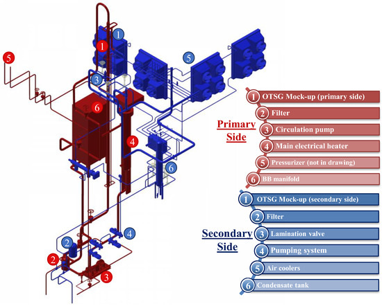
Figure 2.
3D view of the STEAM primary system (red) and secondary system (blue).
Both the systems will be constructed with AISI316 stainless steel, with the exception of the OTSG bundle, which will be made by Inconel. Demineralized water will be used to prevent the accumulation and adherence of limestone, which can increase the thermal resistance of the OTSG tube bundle over the long term. This, in turn, could diminish the T/H performances of the system and potentially result in the formation of plugs that might affect the uniformity of the water flow distribution across the sub-channels. To minimize heat losses to the environment, piping and main components will be thermally insulated using mineral rock wool, which helps to maintain the required operating temperatures within the systems, enhancing the overall efficiency.
The STEAM facility was originally designed to experimentally investigate the thermal-hydraulic behaviour of the EU-DEMO OTSG mock-up, with a power duty of 3.0 MW. To ensure the representativeness of the test section, it has been scaled down from the full-scale DEMO configuration while preserving essential characteristics and performance parameters, considering the constraints of the experimental setup. Specifically, the original design of the STEAM OTSG [14] has been derived from the DEMO Breeding Zone OTSG of the BB PHTS configuration, which featured two 378.5 MW steam generators for the First Wall (FW) and two 581.5 MW for the Breeding Zone (BZ) [12,13]. The scaling factor has been calculated on the basis of the power ratio:
fscaling = PSTEAM/PBZ = 3/581.5 = 0.0052
Tubes number (and flow areas) has been adjusted by multiplying it by the scaling factor while keeping the length constant:
ntubes_STEAM = ntubes_BZ × fscaling = 5696 × 0.0052 = 35.8
However, implementing this tube number with a triangular arrangement would have inevitably resulted in spatial inhomogeneity and adverse effects on the OTSG performances, given that the nearest hexagonal rank was incomplete. To address this issue, the tube number to be installed in the mock-up was rounded to 37, the closest available number within a hexagonal arrangement. Several analyses [14] indicated that this approximation inevitably introduced some distortions in simulating the scaled OTSG mock-up behaviour. For this reason, a new scaling procedure has been considered to match the facility power with the tube count of 37. The scaling approach was therefore changed and also the DEMO BB reference configuration has been modified, foreseeing the merging of the BZ and FW PHTSs in a single system provided with four identical steam generators whose reference power is 477 MW, according to the latest available energy map [15]. The scaling factor has been recalculated based on the tubes ratio:
fscaling = ntubes_STEAM/ntubes_BZ = 37/5696 = 0.0065
Consequently, power and flow areas have been scaled accordingly using the same scaling factor:
PSTEAM = PBZ × fscaling = 477 × 0.0065 = 3.1 MW
This revised scaling approach resulted in a more representative mock−up without introducing significant thermal−hydraulic distortions compared to the DEMO reference configuration [16].
3.1. Primary System
The primary system is a closed loop working at the thermodynamic conditions of the DEMO WCLL BB PHTS [9]. The nominal pressure is 15.5 MPa, while the inlet and outlet temperature of the OTSG are 328 °C and 295 °C, respectively. The OTSG mock-up is designed to exchange a nominal thermal power of 3.1 MW in nominal operation. Based on the BB PHTS thermal cycle, the water mass flow rate required to effectively dissipate the power in nominal conditions is 16.05 kg/s. The primary system Process Flow Diagram (PFD) is reported in Figure 3, while the main working parameters are summarized in Table 2. The primary system of the STEAM facility is made up of several key components, each serving a specific function (the numbers in the list correspond to Figure 2):
- test section 1 (i.e., OTSG, TS-STS-001), is designed to transfer the thermal power generated by the electrical heater to the secondary loop. It is a scaled mock-up (1:1 in tube active length) of the DEMO WCLL BB PHTS OTSGs [17];
- filter (FI-SCL-101), installed on the cold leg, upstream the main circulation pump, with the purpose of capture impurities from the circulating water;
- circulation pump (PL-SCL-101), installed in the cold leg, is a centrifugal pump responsible for circulating water throughout the loop. It can handle a maximum mass flow rate of 20 kg/s;
- heating system (HT-SHT-101), consisting of a stand-off electrically supplied heater. The component consists in a main vessel with an O.D. 26″ and a total length, including the external electrical connections, of about 7.7 m (active length of the heating elements about 3.4 m), and it is designed to deliver a nominal thermal power of 3.1 MW;
- pressurizer (PRZ, not visible in Figure 2, SE-SPZ-101), consisting of a pressurized tank situated along the uppermost leg of the loop (hot leg) used to maintain the pressure of the water circuit to the rated value of 15.5 MPa. The tank contains water at the saturation conditions, partially filled with liquid water and partially with steam The pressure regulation is guaranteed through a spray line that injects cold water from the cold leg and an electrical heater (HT-SHT-102) installed in the pressurizer via a dedicated penetration at the tank bottom. The pressurizer also serves as expansion vessel for the coolant during the start-up heating phases. This component, along with its spray system, is shared with the Water Loop (another facility of the W-HYDRA platform);
- test section 2, a mock-up of the WCLL BB manifold [18], foreseen for the next upgrade of the facility.
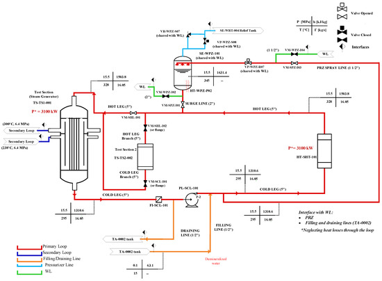
Figure 3.
STEAM primary system Process Flow Diagram.

Table 2.
STEAM primary system main data.
Table 2.
STEAM primary system main data.
| Primary System Nominal Conditions | |||
|---|---|---|---|
| Parameter | Unit | Value | Description |
| Pnom | MW | 3.1 | Nominal power delivered by the TS primary side to the secondary side |
| pH2O,1 | MPa | 15.5 | H2O nominal pressure in the primary side |
| TH2O,in,1 | °C | 328.0 | H2O nominal temperature at the TS inlet |
| TH2O,out,1 | °C | 295.0 | H2O nominal temperature at the TS outlet |
| ΔTH2O,1 | °C | 33.0 | Temp. difference between H2O inlet and H2O outlet |
| ΓH2O,1 | kg/s | 16.05 | H2O nominal mass flow rate |
| Primary system design conditions | |||
| Parameter | Unit | Value | Description |
| pH2O,1 | MPa | 18.5 | Primary system design pressure |
| TH2O,in,1 | °C | 350.0 | Primary system design temperature |
Manual isolation valves allow the interception of the test sections (TSs), the Surge Line, the Spray Line, and the draining line. Pneumatic valves are installed on the Spray Line and on the pressurizer line. A safety valve is installed on the pressurizer to avoid system overpressures. AISI316 stainless steel, characterized by high corrosion resistance and durability, will be used for the loop piping. Mineral wool will be adopted as thermal insulator to minimize heat losses towards the environment.
3.2. Secondary System
The secondary system plays a fundamental role in extracting the thermal power from the primary loop, supplying the feedwater to the OTSG mock-up during all the different operational phases of the facility. The loop replicates the conditions of the DEMO Power Conversion System (PCS), which entails an operating pressure of 6.4 MPa and OTSG inlet-outlet temperatures of 238–300 °C. Considering the PCS thermal cycle, the feedwater mass flow rate needed to efficiently remove the power in nominal conditions is 1.68 kg/s. In particular, the loop is divided in two sectors: the first one including the OTSG mock-up is operated at the DEMO PCS conditions (see above), while the second one, including the final heat sink of the facility (i.e., the Air Coolers, AC), is operated at 2.5 MPa with a thermal cycle of 245.4–210.0 °C. The secondary system PFD is reported in Figure 4, while main working parameters are summarized in Table 3.
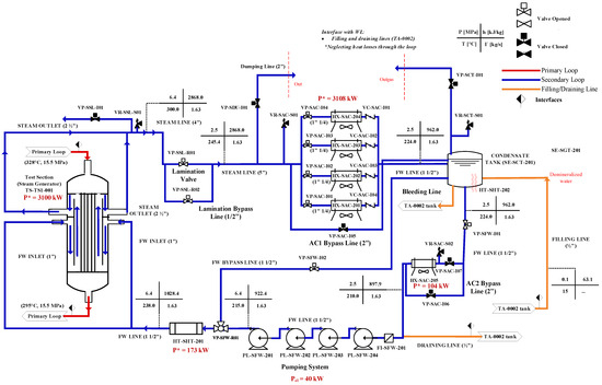
Figure 4.
STEAM secondary system Process Flow Diagram. The red dashed lines indicate the boundary with the external environment.

Table 3.
STEAM secondary system main data.
The pressure reduction from 6.4 MPa to 2.5 MPa is achieved through the use of a lamination valve installed on the steam line, operating with superheated steam both upstream and downstream the valve itself, while set of four magnetic drive centrifugal pumps installed on the feedwater line provides the head required to increase the pressure from 2.5 MPa to 6.4 MPa. A dedicated electrical heater is installed upstream the OTSG to heat the feedwater up the nominal temperature of 238 °C. The adoption of the lamination process with pressure reductio is performed to hydraulically decouple the OTSG mock-up from the heat sink related systems, preventing the propagation of eventual instabilities and perturbations occurring in this section of the circuit towards the OTSG. The main components of the STEAM secondary system are (numbers of the list below are referred to Figure 2):
- TS 1 (i.e., OTSG, TS-STS-001), designed to deliver to the secondary loop the thermal power supplied by the electrical heater;
- Filter (FI-SFW-201), installed on the cold leg, upstream the circulation pumps. It helps ensuring that the feedwater is free from impurities;
- lamination valve (VP-SSL-R01), installed on the steam line is used to reduce the pressure from 6.4 MPa to 2.5 MPa;
- pumping system (PL-SFW-201/202/203/204), consisting of a set of four magnetic drive centrifugal pumps installed in the cold leg. They are responsible for circulating the feedwater throughout the loop, with a maximum mass flow rate of 2 kg/s;
- air coolers (HX-SAC-201/202/203/204/205), serving as the final heat sink of the system, these components are designed to remove the thermal power delivered by the OTSG to the secondary loop. The ACs have in charge the de- superheating of the steam up to the saturation conditions and the condensation of all the steam flow (four modules upstream the condensate tank). Then, they cool the resulting liquid water to a final temperature few degrees below the saturation temperature at the corresponding operating pressure (one module downstream the condensation tank);
- condensate tank (SE-SCT-201), a pressurized tank placed downstream the de-superheating set of four parallel ACs. It is partially filled with liquid water and partially with steam, both in saturation conditions, since it collects the saturated feedwater coming from the air coolers, keeping 224 °C and 2.5 MPa. Pressure regulation is achieved through an electrical heater (HT-SHT-202) installed in the tank through a designated penetration at its bottom and a gas outlet line with a self-controlled relief valve to avoid eventual over-pressurizations. Additionally, it is equipped with a bleeding line for controlled discharges and a filling line for refilling, enabling water level control within the tank.
Furthermore, a heating system (i.e., a stand-off electrically supplied heater) is used to heat the water downstream the pump up to the feedwater temperature required at the OTSG inlet (i.e., 238 °C). The component, a 10″ vessel with an active length of about 3.0 m, is designed to supply a maximum thermal power of about 200 kW.
Manual isolation valves are installed on the draining line. Pneumatic valves are deployed at several strategic points in the system, including on the bleeding line to control the water discharge, on the air coolers admission lines to regulate the flow rate inside the ACs, on the ACs bypass lines, on the feedwater line downstream the condensate tank, on the pumping system recirculation line, on the dumping lines and downstream the pumping system to control and adjust the feedwater flow rate to the OTSG (3-way valve). Safety valves are installed on the steam line, on the condensate tank and on the air coolers. Check valves are placed on the filling line, as well as downstream each one of the air cooler modules (with the exception of the sub-cooling module).
3.3. Test Section
As seen before, the OTSG mock-up for the STEAM facility, depicted in Figure 5, was developed through a scaling procedure based on the “power to volume” approach. It was designed to maintain the full length scale of the Breeding Zone OTSG [19], which, in turn, is inspired to the Babcock & Wilcox (B&W) layout [20,21], suitably adapted to DEMO considering the thermo-dynamic constraints for PHTSs and PCS.

Figure 5.
BB OTSG (left) and STEAM OTSG mock-up (right). The red square indicates the hight where the cross section is provided.
The design phase has been supported with RELAP5/Mod3.3 [22] thermal-hydraulic analyses. A preliminary qualification activity on the basis of the Babcock & Wilcox (B&W) OTSG of Three Miles Island (TMI) data [19,21] has been performed, proving the suitability of the code for the purposes of the design activity. The configuration obtained [14] keeping the same layout of the reference case (i.e., BZ OTSGs), would be characterized by a 2 cm thick annular downcomer, which is not feasible not only for the tolerances of coaxial pipes but also for the installation of instrumentation in the component. For this reason, two different constructive solutions have been investigated, with one or two external DC tubes, respectively This variation is pursued by adopting the DC scaled area for the case with one external pipe, and its half value for both the DCs in the case with two external pipes. After the RELAP5/Mod.3.3 analysis [14], the model with one external downcomer for the feedwater and one external downcomer for the steam has been adopted. In fact, assuring the removal of the required power, with respect to the full-size reference OTSG configuration:
- introduces low pressure drop distortions;
- avoids parallel channels instability (which can occur in the two-external-downcomer configuration);
- eliminates problem related to manufacturing of an integrated annular DC.
The BB OTSG and the final layout of the STEAM mock-up are depicted in Figure 5.
On the STEAM mock-up primary side, the water enters from the top through an upper inlet nozzle, and it flows in an upper plenum, from which it is distributed inside the tube bundle (tubes side), composed by 37 tubes arranged with a triangular pitch in a hexagonal shell. After the passage through the tube bundle, the cooled water is collected in the lower plenum, and it exits through the lower outlet nozzle. On the secondary side, the water enters from an inlet nozzle, where it is mixed with riser-spilled vapor and it flows downward through an external downcomer (DC). Once reached the lower part, the water enters in the riser region and it flows upward across the shell side of the tube bundle, where the vaporization occurs. After the passage through the riser, the steam produced exits through the outlet nozzle. The comparison between the geometrical features of the BB PHTS OTSG and the STEAM mock-up are reported in Table 4.

Table 4.
Comparison between BB PHTS and STEAM scaled-down OTSG geometrical features.
3.4. Instrumentation
For an experimental facility, it is paramount to have a comprehensive data collection. Achieving a deep understanding of the system during all the operative states that will be tested requires meticulous monitoring and measurement of various parameters, which is STEAM primary aim. A strategic placement of a large number of thermocouples, pressure transducers, differential pressure transducers, flow meters, and level sensors has been done, facilitating the capture of a wealth of data and safeguarding the facility integrity.
3.4.1. Thermocouples
A comprehensive network of bulk and wall thermocouples (TCs) has been strategically positioned to facilitate temperature monitoring across the facility critical points. This meticulous placement of sensors is crucial to ensure the precise control and measurement of temperature parameters throughout the experimental setup.
Primary system. Bulk and wall TCs have been positioned both upstream and downstream of the OTSG to monitor the inlet and outlet temperatures. Such TCs are required to control that the water inlet and outlet temperature is in the range prescribed for the operation of the mock-up, i.e., Tin/out = 328 °C/295 °C. TCs are also installed in correspondence of the nozzles themselves, providing redundant information in case of malfunctioning of the other systems. Inside the OTSG mock-up, temperature monitoring extends to assess the plena temperature, thereby ensuring a comprehensive understanding of the thermal characteristics within the generator. Moreover, temperature assessment spans across the active length of the OTSG tube bundle through the placement of bulk TCs inside the primary side tube. These TCs, distributed across various sections, comprise four TCs at each section, arranged at five different height levels, spaced at intervals of 3.2 m, assuming that the heights are measured starting from the upper part of the lower tube sheet. TCs have been located in correspondence of the pump suction and the discharge point, facilitating the measurement of water heating occurring across the pump. A similar approach has been adopted for the electrical heater, with TCs positioned both upstream and downstream the component, to regulate the power on the basis of a temperature set-point. Two bulk TCs are designed for installation at the heater inlet and outlet nozzles, complemented by four wall TCs positioned along the heater’s length to facilitate heat loss calculations.
Within the PRZ component, an extensive network of temperature sensors (bulk TCs and wall TCs) is distributed along its length. These sensors serve multiple purposes, from monitoring the maximum height of the PRZ heaters, to tracking water temperatures below and above the free level, facilitating temperature measurement in case of system overpressure. The installation of internal and external wall TCs, strategically positioned at specific distances from the PRZ bottom, aids in heat loss calculations for different regions of the PRZ. A bulk TC is positioned to monitor both spray and surge line, tracking in this way the temperature of the water entering or exiting the pressurizer. Additional TCs are dedicated to the continuous control of the water temperature in correspondence of the Safety Relief Valve (SRV) and the Pressure Operated Relief Valve (PORV), ensuring safety protocols are maintained.
The extensive data collection approach also extends to the hot and cold legs. Here, a large number of bulk, internal wall, and external wall TCs have been thoughtfully positioned at intervals of 4 m, providing valuable insights into heat losses along the loop. This arrangement contributes significantly to the comprehensive understanding of the system’s thermal behavior. Lastly, bulk TCs have been strategically installed both upstream and downstream the Test Section 2, further enriching the dataset for analysis and assessment.
Secondary system. TCs are installed upstream the OTSG feedwater inlet nozzle and downstream the OTSG steam outlet nozzle to monitor the inlet and outlet temperature. Their primary function is to ensure that in nominal operation the feedwater inlet temperature is at the prescribed value of 238 °C and the steam outlet temperature is maintained at 300 °C in nominal conditions. TCs are also installed in correspondence of the nozzles themselves, providing redundant information in case of malfunctioning of the other systems. Temperature monitoring extends within the OTSG mock-up and along the active length of the OTSG tube bundle. A network of TCs is strategically planned for installation across five different sections. These TCs are tasked with monitoring temperatures on both the secondary side water and primary side tube walls. The sections are positioned at five different levels, maintaining a mutual distance of 3.2 m in height, with the upper part of the lower tube sheet serving as the reference point. Given the triangular tube pitch, TCs are arranged at the vertices of equilateral triangles (at 120°) across the same positions at these five different levels. This arrangement facilitates the capture of temperature data from the central channel, two medium channels, two external channels (symmetrically chosen with respect to the center), and the axial thermal characterization of the bypass region. Additional sensors include bulk TCs in the riser low liquid part, bulk TCs positioned in correspondence of the riser liquid collapsed level, and further TCs distributed along the riser height in the superheating zone. Additional internal and external wall TCs are positioned along the riser length at a mutual distance of 1 m, providing the heat losses calculation. Temperature monitoring through bulk TCs further extends to various key points, including upstream and downstream the pumping system, the electrical heater, the lamination valve, the cooling system (air coolers), and the condensate tank. Bulk and wall TCs are also densely distributed along the length of the heater and the tank, along with the tank outlet gas line and the filling and bleeding line.
Bulk, internal wall and external wall TCs are finally installed at a mutual distance of 4 m along the hot leg (steam line) and cold leg (feedwater line) to gain feedback on the heat losses along the loop.
3.4.2. Pressure Transducer and Differential Pressure Transducers
Pressure transducers (PCs) are used in order to measure the absolute pressure in the critical points of the circuit and differential pressure transducers (PTs) are used for pressure measurements inside the main components and along the loops, in order to monitor the pressure drops.
Primary system. PCs are positioned upstream several components to control pressure at key locations. These PCs are placed upstream the pump to monitor the pressure at the pump suction, ensuring the pump operates within specified parameters. Similarly, PCs are deployed upstream and downstream the heater to regulate pressure at the heater inlet and outlet sections. Additionally, PCs are installed upstream and downstream the OTSG to control the inlet and outlet pressures. The PRZ is equipped with PCs to control internal tank pressure, keeping it at the required set-point value. The PC signal in the PRZ is used to control the intervention of the relief valve and the valve on the spray line in case of over-pressurization, as well as to regulate the power of the electrical heater in case of depressurization. For redundancy, additional PTs are installed in the upper part of the pressurizer and a further PT is installed on the vapor discharge line.
Furthermore, PTs are installed to measure the pressure difference: across the pump, the electrical heater, the filter, the pressurizer, the OTSG and along the hot leg. Other PTs are installed in order to evaluate the pressure difference 0.10 m below and above the pressurizer free level and in correspondence of the pressurizer heaters. The surge line is also equipped with a PT in order to monitor the pressure difference between hot leg and pressurizer.
Secondary system. PTs are installed upstream and downstream the pumping system, the electrical heater, the lamination valve and the cooling systems (i.e., the air coolers). They are placed also upstream the OTSG feedwater inlet section and downstream the OTSG steam outlet section, to monitor the OTSG inlet and outlet pressure and upstream, downstream and inside the condensate tank, in order to control the pressure inside the component (and in the section of the loop between the lamination valve outlet and the pump system inlet), keeping it at the set-point value (2.5 MPa in nominal operation). The signal of the PC in the tank is used to control the intervention of the relief valve in case of over-pressurization and the valve on the gas injection line in case of depressurization. The gas discharge line is also equipped with a PC, in case of malfunctioning of the PC inside the condensate tank. Furthermore, PTs are installed to measure the pressure difference across the OTSG riser collapsed level, the OTSG feedwater line, the OTSG steam line, the total OTSG, the air coolers. Similarly, they are also placed to measure the pressure difference between the aspirator port and the feedwater inlet, across the de-superheating air cooler, the condensate tank and below and above the tank free level.
3.4.3. Flow Meters
Flow meters (MFs) are used to measure the water mass flow rate in the primary loop and secondary loop. In the primary loop, two flow meters will be installed on the cold leg, downstream the circulation pump, while on the secondary loop, two flow meters will be installed on the feedwater line, downstream the pumping system. The two flow meters installed on each system will be chosen with a different principle of measurement (i.e., Coriolis flow meter and ultrasonic flow meter). The signals acquired from the flow meters will be used to regulate the pumps round per minutes and, thus, the provided mass flow rate.
3.4.4. Level Sensors
Level sensors (LMs and LVs) are used to detect the water level inside the pressurizer and the condensate tank in the primary loop and secondary loop, respectively. In both cases, the control of the level is performed by installing three sensors, positioned at different depth, allowing in this way to acquire the signal of the “high level” (ON/OFF measurement LV), “low level” (ON/OFF measurement LV) and “total liquid level” (continuous measurement LM). As regards the pressurizer, the level sensor is installed in the low part of the tank, above the PRZ heaters, so that the measurement would trigger the safety protection in time for avoiding the heating bars superheating. No such problem occurs in the condensate tank, where the low level signal is installed to assure that a minimum amount of water for the loop operation is available in the tank. The high level signals are installed in the higher part in order to avoid the systems to become “solid”, losing the capacity of pressure regulation. The total level sensors are positioned on the upper head of both the systems, in order to provide the measurement of the total inventory of water.
4. STEAM Operational States
The STEAM facility is conceived to operate at different power levels, accordingly to the requirements of the experiments. A set of conditions to be achieved by the facility to execute an experiment (i.e., mass inventory, power level, pressure, temperature) identifies a specific operational state. Six different operational states have been defined, as reported in Table 5. The first three (from 1 to 3 in Table 5) are intermediate states which must be achieved by the facility in order to reach step by step the final conditions for the experiments:
- cold-drained: the facility is empty (mass inventory 0%) and at zero power. The pressure inside the primary and secondary systems is the atmospheric pressure and the temperature corresponds to the environmental temperature. In the secondary loop, the feedwater line and the lamination valves on the steam line are closed;
- cold-filled: the facility is filled (mass inventory 100%) after the filling procedure and kept at zero power. The pressure inside the primary and secondary systems is the atmospheric pressure and the temperature corresponds to the environmental temperature. In the secondary loop, the feedwater line and the lamination valves on the steam line are closed;
- hot pressurized/standby: the primary system is heated up to 280 °C (corresponding at the saturation temperature at 6.4 MPa) and the pressure achieved is 15.5 MPa, while the pump is switched on and it elaborates the nominal flow rate. In this state, the system is still in “zero power” condition, but the heater may be activated for heat loss compensation, in case the power released by the pump to the fluid is not enough to balance the power lost towards the environment. In the secondary system, both the feedwater line and the lamination valves on the steam line are closed. The high pressure section (i.e., the section including the OTSG) reaches the equilibrium with the primary system, achieving the saturation temperature of 280 °C at the corresponding pressure of 6.4 MPa. Eventual over-pressurization will be avoided by opening the OTSG dumping line. On the low pressure section, the pumping system provides the nominal flow rate, which is deviated to the recirculation line by the 3-way valve (feedwater line closed), heating up the water up to 224 °C, reaching the saturation temperature at the corresponding pressure of 2.5 MPa. The set-point pressure of 2.5 MPa is kept constant by a proper regulation of the electrical heater and relief valve installed in the condensate tank.
After the achievement of the state “Hot pressurized/Standby”, the other sets of conditions (from 4 to 6 in Table 5) correspond to operational states in which the experiments are performed:
- low power steady state (<20%, open loop): in this state, the primary system is operated supplying a thermal power by the electrical heater less than 20% of the nominal value. The pressure is kept at 15.5 MPa and the OTSG inlet temperature is set at 328 °C, while the pump elaborates the flow rate necessary to achieve the temperature at the OTSG outlet at the value required by the experiment. In the secondary system, both the feedwater line and the lamination valve on the steam line are open. The high pressure section operates at the nominal pressure of 6.4 MPa. Downstream the lamination valve, the air coolers are switched off and closed, while the dumping line is open, allowing the operation of the system as an open loop, by discharging in the environment the steam produced by the OTSG. The water lost as superheated steam is re-integrated by opening the filling line connected to the condensate tank. On the low pressure section, the pumping system provides the nominal flow rate, which is partially deviated to the recirculation line by the 3-way valve (feedwater line partially open), heating the water up to 224 °C, reaching the saturation temperature at the corresponding pressure of 2.5 MPa. The set-point pressure of 2.5 MPa is kept constant by a proper regulation of the electrical heater and relief valve installed in the condensate tank. The electrical heater downstream the 3-way valve is activated in order to pre-heat the feedwater at the temperature value required by the experiment;
- low power steady state (closed loop): also in this state, the primary system is operated at low power (i.e., small power fraction supplied by the main electrical heater). The pressure is kept at 15.5 MPa and the OTSG inlet temperature is set at 328 °C, while the pump elaborates flow rate necessary to achieve the temperature at the OTSG outlet as required by the experiment. In the secondary system, both the feedwater line and the lamination valve on the steam line are open, allowing the operation of the entire loop. The high pressure section operates at the nominal pressure of 6.4 MPa. Downstream the lamination valve, the air coolers are switched on, performing the de-superheating and the condensation of the steam produced in the OTSG, allowing in such a way the operation of the system as a closed loop. The condensate is collected inside the condensate tank, kept at 224 °C and 2.5 MPa. The set-point pressure of 2.5 MPa is kept constant by a proper regulation of the electrical heater and relief valve installed in the condensate tank. The pumping system provides the nominal flow rate, which is partially deviated to the recirculation line by the 3-way valve (feedwater line partially opened). The electrical heater downstream the 3-way valve is activated in order to pre-heat the feedwater at the temperature value required by the experiment;
- full power steady state: the primary system is operated at the nominal power (i.e., 3.1 MW supplied by the main heater). The pressure in kept at 15.5 MPa and the OTSG inlet-outlet temperature is 328–295 °C, while the pump elaborates the nominal flow rate. In the secondary system, both the feedwater line and the lamination valve on the steam line are open. The high pressure section operates at the nominal pressure of 6.4 MPa, with a OTSG inlet-outlet temperature of 238–300 °C. Downstream the lamination valve, the air coolers are switched on, performing the de-superheating and condensation of the steam produced in the OTSG, allowing in such a way the operation of the system as a closed loop. The condensate is collected inside the condensate tank, which is kept at 224 °C and 2.5 MPa. The pumping system elaborates the nominal flow rate to the feedwater line (recirculation line closed). The electrical heater downstream the 3-way valve is activated in order to pre-heat the feedwater up to 238 °C.

Table 5.
List of the STEAM facility operational states.
Table 5.
List of the STEAM facility operational states.
| # | Operating Stages | Conditions | |
|---|---|---|---|
| Primary Side | Secondary Side | ||
| 1 | Cold-drained | Mass inventory: 0% Power: 0 kW Pressure: 0.1 Mpa Temperature: 20 °C | Mass inventory: 0% Power: 0 kW Pressure: 0.1 MPa Temperature: 20 °C FW line closed/Lam. Valve closed |
| 2 | Cold-filled | Mass inventory: 100% Power: 0 kW Pressure: 0.1 MPa Temperature: 20 °C | Mass inventory: 100% Power: 0 kW Pressure: 0.1 MPa Temperature: 20 °C FW line closed/Lam. Valve closed |
| 3 | Hot-pressurized/ Standby | Mass inventory: 100% Power: 0 kW Pressure: 15.5 MPa Temperature: 280 °C | Mass inventory: 100% Power: 0 kW Pressure OTSG: 6.4 MPa Temperature OTSG: 280 °C FW line closed/Lam. Valve closed Pressure CT: 2.5 MPa Temperature CT: 224 °C |
| 4 | Low power SS (<20%, open loop) | Mass inventory: 100% Power: TBD (<20%) Pressure: 15.5 MPa Temperature: 328-YY°C | Mass inventory: 100% Power: TBD (<20%) Pressure OTSG: 6.4 MPa Temperature OTSG: range TBD FW line open/Lam. Valve open Dumping Line open ACs switched off and closed Pressure CT: 2.5 MPa Temperature CT: 224 °C |
| 5 | Low power SS (closed loop) | Mass inventory: 100% Power: TBD Pressure: 15.5 MPa Temperature: 328–YY °C | Mass inventory: 100% Power: TBD Pressure OTSG: 6.4 MPa Temperature OTSG: range TBD FW line open/Lam. Valve open Pressure CT: 2.5 MPa Temperature CT: 224 °C |
| 6 | Full power SS | Mass inventory: 100% Power: 3100 kW Pressure: 15.5 MPa Temperature: 328–295 °C | Mass inventory: 100% Power: 3100 kW Pressure OTSG: 6.4 MPa Temperature OTSG: 238–300 °C FW line open/Lam. Valve open Pressure CT: 2.5 MPa Temperature CT: 224 °C |
5. STEAM OTSG Control
Scope of this section is the definition of the control strategy for the OTSG mock-up of the STEAM facility. The regulation strategy to be employed for the dwell phase is a critical element for the operation of WCLL OTSG, and thus obviously for STEAM, given the peculiar conditions characterizing this phase (1% load is far from the standard operating window of fission NPP OTSG) and the extremely fast fusion power ramps that the OTSG will have to face (much harder than typical fission NPP transients). As starting point, the B&W regulation strategy reported [20,23,24,25] is assessed. The standard control strategy adopted by B&W in NPP OTSGs is:
- at loads between 15% and full power, the control system regulates the feedwater flow rate to keep constant the primary circuit average temperature;
- at loads below 15%, the OTSG control strategy switches to a level-control logics that regulates the feedwater flow rate to keep a constant shell-side water level;
- across the whole operating range, B&W control dictates that the secondary-side pressure is held constant by regulation of turbine bypass valves.
With respect to the standard regulation employed in fission NPPs, the control strategy for WCLL OTSG (and thus STEAM OTSG) shall fulfil very different requirements. Indeed, while in fission NPPs the very low loads are only of interest during start-up and shutdown, the pulsed operation of DEMO means that the system will face a very large number of thermal cycles and with very fast transients. In light of this, the following requirements are taken into account in STEAM OTSG control design:
- ensure a sufficiently strict control of the Primary Loop temperatures during the pulse → dwell and dwell → pulse transitions;
- limit as far as possible the amplitude of the thermal cycling of primary side components;
- ensure that the OTSG operates in a range of thermal-hydraulic parameters that is dynamically stable.
Clearly, some of the aspects mentioned above are partially in conflict with each other. In addition, although the first phase of STEAM operation will deal only with low (1%) power tests (i.e., dwell phase), it considered important that all the above requirements are considered from the onset of control design, as they will have an impact on the selection of the control strategy for the dwell phase. In light of these considerations, two different control strategies are developed and tested, both keeping the primary mass flow constant and regulating the feedwater mass flow to follow a temperature set-point in the primary loop:
- control scheme 1 regulates the OTSG feedwater flow to keep at setpoint the Primary Loop average temperature—i.e., (TcoldLeg + ThotLeg)/2—both in pulse- and dwell-phase (both Tmin and Tmax are free to move according to the load);
- control scheme 2 regulates the OTSG feedwater flow to keep at setpoint the Primary Loop cold leg temperature, both in pulse- and dwell-phase (Tmin is fixed and Tmax is free to move following the load).
The control schemes are tested on a STEAM dynamic simulator specifically implemented using the 1D Modelica language version 3.5 [26] and simulated using the Dymola environment from Dassault Systèmes Version 2022 [27]. Validated components of the ThermoPower thermal-hydraulic library [28] have been employed. This approach is identical to the one commonly employed by PoliMi for dynamics modeling & simulation and for control design in fission power field (e.g., [29]). Both the primary loop and the OTSG are completely reproduced, while, concerning the secondary loop, only the section between the heater HT-SHT-201 and the lamination valve VP-SSL-R01 is modeled. This open-loop assumption is equivalent to assuming that the choked valve VP-SSL-R01 effectively decouples the dynamics of the test section from the rest of the loop.
The reproduced power ramps of the heater HT-SHT-101 are assumed to have the same “shape” (power vs. time) of the realistic fusion power ramps indicated in [30]. The heater power is assumed to be 3 MW in pulse and 30 kW in dwell, according to the STEAM previous reference configuration [16], but results are still representative for the new power (i.e., 3.1 MW).
The controller employed, a conventional PI (Proportional-Integral) controller whose parameters have opportunely been tuned, is parametrized in the following form:
where: u = TsetPoint − Tmeasured and y = feedwater flow rate
y = k × (1 + 1/(Ti × s)) × u
The output signal of the PID (Proportional-Integral-Derivative) provides the setpoint for the feedwater mass flow rate low-level control system, which controls the secondary loop pumps speed based on the signal from flowmeter MF-SFW-201. Control block schemes are reported in Figure 6 and Figure 7, respectively.
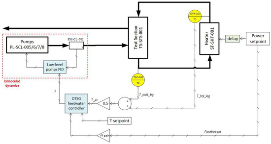
Figure 6.
Control block scheme for control strategy 1.
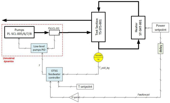
Figure 7.
Control block scheme for control strategy 2.
From the comparison of the results of Figure 8 and Figure 9, an improvement in the readiness of the control can be noticed in the scheme 2, where the system reaches steady states significantly faster and with reduced peaks in feedwater mass flow rates. The reason is that this control logics adopts as only temperature feedback signal the OTSG tube-side outlet: this signal has minimal measurement delay and the heater dynamics does not act as a practical output disturbance directly on a feedback signal. On the contrary, the tube-side inlet temperature measurement presents a significant time delay since the heater power, which can be interpreted as a sort of output disturbance—acts between the control action and the measurement point.
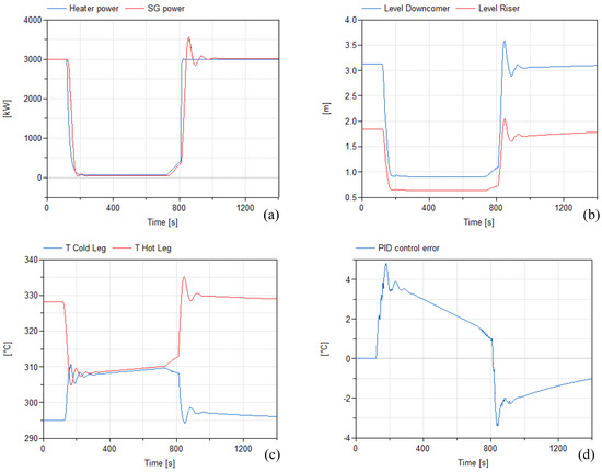
Figure 8.
Simulations results for Control Strategy 1 (average-T control) during pulse-dwell-pulse transitions—without feedforward action. Pulse → dwell starts at 100 s, dwell → pulse starts at 720 s. The figure shows, from left to right, from top to bottom: (a) power, (b) levels, (c) primary side temperatures, (d) control error, (e) mass flow rates, (f) steam T.
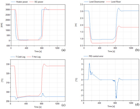
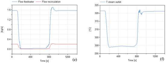
Figure 9.
Simulations results for Control Strategy 2 (cold-leg-T control) during pulse-dwell-pulse transitions—without feedforward action. Pulse → dwell starts at 100 s, dwell → pulse starts at 720 s. The figure shows, from left to right, from top to bottom: (a) power, (b) levels, (c) primary side temperatures, (d) control error, (e) mass flow rates, (f) steam T.
In both cases, control action—i.e., the feedwater ramps—is not fast enough to follow the rapid heater power ramps. This limitation can however be partially overcome by employing a suitable feedforward action. The most appropriate action is identified to be based on the input power to the heater. Indeed, this feedforward can be more properly described as a predictive action, as it anticipated of 20 s with respect to the actual beginning of the heater power ramps. The improvement brought by the feedforward action on control performance can be clearly seen from Figure 10 and Figure 11. “Anticipating” the upcoming power ramps to the control system allows the latter to synchronize the feedwater ramps much better, allowing a much stricter and faster control of the temperature of interest. This has a limited effect on steady-state dwell operation of the first phase of STEAM, but it has a rather important impact in perspective of pulse-dwell-pulse transitions experimental tests.
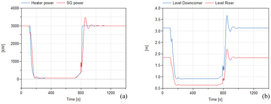
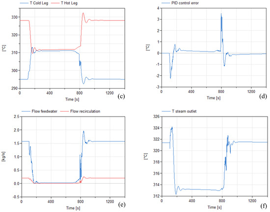
Figure 10.
Simulations results for Control Strategy 1 (average-T control) during pulse-dwell-pulse transitions—with feedforward action. Pulse → dwell starts at 100 s, dwell → pulse starts at 720 s. The figure shows, from left to right, from top to bottom: (a) power, (b) levels, (c) primary side temperatures, (d) control error, (e) mass flow rates, (f) steam T.
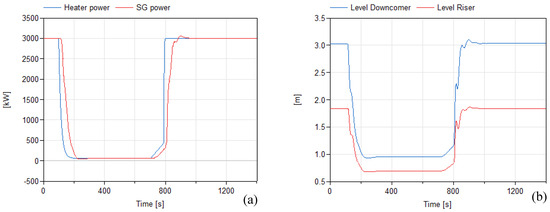
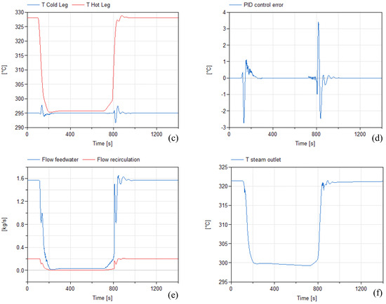
Figure 11.
Simulations results for Control Strategy 2 (cold-leg-T control) during pulse-dwell-pulse transitions—with feedforward action. Pulse → dwell starts at 100 s, dwell → pulse starts at 720 s. The figure shows, from left to right, from top to bottom: (a) power, (b) levels, (c) primary side temperatures, (d) control error, (e) mass flow rates, (f) steam T.
Both schemes show, in the limits of the modeling assumptions, acceptable performances: the dynamic response of the system and the control bandwidth are sufficiently fast to ensure a rather strict control of the temperatures of interest, with only slight overtemperatures caused in particular by the very steep power ramp of the dwell-pulse transition. Pros and cons of the two regulation logics can be summarized as:
- -
- strategy 1 limits the maximum amplitude of the thermal cycling of the components, as well as maximum change rate of the temperatures. Under Strategy 2, instead, components on the hot side (blanket/heater outlet, hot leg, OTSG tube inlet) see the whole temperature excursion of roughly 33 °C (on the other hand, cold side components see almost no cycling under Strategy 2);
- -
- strategy 1 causes a much easier pressurizer transient, as the average Primary Loop density is practically constant. The pressurizer transient for Strategy 2 might be harder and more complex, due to the fast variation of average density in the loop;
- -
- strategy 1, employing as feedback to the control loop a temperature signal with a significant delay and fast and strong output disturbance, can obtain a less “strict” tuning of PID parameters. Strategy 2 can obtain a higher control bandwidth and thus a more “reactive” control, allowing stricter temperature control;
- -
- strategy 2 allows to prevent any overtemperature in the Primary Loop during the very hard power ramp of the dwell → pulse transition. On the contrary, with Strategy 1 we have, in dwell, the whole Primary Loop filled with water at 311–312 °C: the steepness of the power ramp makes it impossible to avoid overtemperatures at heater—respectively, blanket for WCLL—outlet, with associated risks of local saturation;
- -
- under strategy 2, the T/H conditions of the OTSG in dwell are much closer to those characterizing the low power operation under the validated B&W NPP OTSG control strategy. Strategy 1 causes T/H dwell conditions (log-mean ΔT, levels) that are significantly off from validated operation;
- -
- strategy 2 allows to easily avoid, during transitions, a possible oscillatory window that may occur at around 15–20% of nominal feedwater flow rate in presence of high log-mean ΔT. Under Strategy 1, there is a higher risk of crossing that operational window.
6. Conclusions
STEAM facility stands as a cornerstone within the realm of fusion experimental research. Designed to replicate the DEMO PHTS and PCS thermodynamic conditions, its primary objective is to serve as a rigorous testing ground for the EU-DEMO Once-Through Steam Generator (OTSG) mock-up. The paramount goal is to qualify the OTSG through a comprehensive evaluation process, ensuring its efficiency, safety, and performance within the extreme operational parameters of a fusion reactor. The design of such component has been obtained adopting a scaling procedure, the optimization of which led to an increment in facility power from 3.0 to 3.1 MW to be more representative of the DEMO reference configuration. Given its nature as an experimental facility, the deployment of an extensive sensor network is of paramount importance. These sensors play a pivotal role in monitoring relevant parameters such as temperature, pressure, flow rates, and water levels in both the primary and secondary systems. This comprehensive monitoring not only safeguards the facility integrity but also ensures the collection of important data for characterizing the OTSG during all the operational phases outlined in this study. Notably, two distinctive control strategies for the OTSG have then been identified to address the unique challenges of rapid transitions between pulse and cooldown phases in the context of high-power nuclear fusion. Through 1D numerical simulations carried out with the MODELICA language Version 3.5, the performances of both strategies have been evaluated and compared and their strengths and weaknesses have been identified. In particular, the influence of the feedforward action on the transient evolution has been assessed and its related capability of enhancing the system responsivity has been shown. Ultimately, given that both the controller guarantee a safe transition between different power loads, the choice between Control Scheme 1 and Control Scheme 2 will be done on the basis of the experimental results and will depend on their ability to meet the specific requirements of STEAM, ensuring stable and safe operation during rapid power ramp-ups.
Author Contributions
Conceptualization, A.V., P.L., A.D.N. and M.E.; methodology, A.V., P.L., C.T. and A.D.N.; software, A.V., F.G., C.C. and A.T. (Andrea Tarallo); validation, A.V., P.L. and A.D.N.; formal analysis, A.V., P.L., C.T. and A.D.N.; investigation, A.V., P.L., P.A. (Pietro Arena), C.T., A.D.N., M.E., A.T. (Amelia Tincani), F.G., N.B. and C.C.; resources, A.D.N.; data curation, A.V. and P.L.; writing—original draft preparation, A.V. and P.L.; writing—review and editing, A.V., P.L., P.A. (Pietro Arena), M.E., F.G., R.M., C.C., N.B., A.C., A.T. (Amelia Tincani) and A.D.N.; visualization, A.V. and P.L.; supervision, A.D.N., M.E., R.M., A.T. (Amelia Tincani), L.B., P.A. (Pietro Agostini) and F.G.; project administration, A.D.N. and M.E.; funding acquisition, A.D.N. All authors have read and agreed to the published version of the manuscript.
Funding
This research was funded by the European Union via the Euratom Research and Training Programme, grant number 101052200.
Data Availability Statement
Data are contained within the article.
Acknowledgments
This work was carried out within the framework of the EUROfusion Consortium. The views and opinions expressed are, however, those of the author(s) only and do not necessarily reflect those of the European Union or the European Commission. Neither the European Union nor the European Commission can be held responsible for them.
Conflicts of Interest
The authors declare no conflict of interest. The work was carried out within the framework of the EUROfusion Consortium. The views and opinions expressed are, however, those of the authors only and do not necessarily reflect those of the European Union or the European Commission. Neither the European Union nor the European Commission can be held responsible for them.
References
- Donné, A.J.H. European roadmap to fusion energy. In Proceedings of the 2018 Symposium on Fusion Technology (SOFT), Giardini Naxos, Italy, 16–21 September 2018. [Google Scholar]
- Donné, T.; Morris, W. European Research Roadmap to the Realisation of Fusion Energy; EUROfusion: Garching/Munich, Germany, 2018; ISBN 978-3-00-061152-0. [Google Scholar]
- Federici, G.; Boccaccini, L.; Cismondi, F.; Gasparotto, M.; Poitevin, Y.; Ricapito, I. An overview of the EU breeding blanket design strategy as an integral part of the DEMO design effort. Fusion Eng. Des. 2019, 141, 30–42. [Google Scholar] [CrossRef]
- Muratov, V.P.; Saksagansky, G.L.; Filatov, O.G. ITER—International Thermonuclear Experimental Reactor. In Fundamentals of Magnetic Thermonuclear Reactor Design, Woodhead Publishing Series in Energy; Woodhead Publishing: Sawston, UK, 2018; pp. 39–67. [Google Scholar] [CrossRef]
- Ibarra, A.; Kurtz, R. ITER-TBM and Blanket Programs toward DEMO. In Proceedings of the 3rd IAEA DEMO Programme Workshop, Hefei, China, 11–14 May 2015; Available online: https://nucleus.iaea.org/sites/fusionportal/Technical%20Meeting%20Proceedings/3rd%20DEMO/website/talks/May%2013%20Sessions/Ibarra_A%20Intro.pdf (accessed on 8 July 2022).
- Federici, G.; Baylard, C.; Beaumont, A.; Holden, J. The plan forward for EU DEMO. Fusion Eng. Des. 2021, 173, 112960. [Google Scholar] [CrossRef]
- Available online: https://www.euro-fusion.org/ (accessed on 30 June 2022).
- Spagnuolo, G.A.; Boccaccini, L.V.; Bongiovì, G.; Cismondi, F.; Maione, I.A. Development of load specifications for the design of the breeding blanket system. Fusion Eng. Des. 2020, 157, 111657. [Google Scholar] [CrossRef]
- Vallone, E.; Bongiovì, G.; Di Maio, P.A.; Moscato, I.; Quartararo, A.; Vacca, S. Development of a thermal-hydraulic model of the EU-DEMO Water Cooled Lithium Lead Breeding Blanket Primary Heat Transport System. Fusion Eng. Des. 2023, 193, 113686. [Google Scholar] [CrossRef]
- Szogadri, M.; Norrman, S. Model Development and Transient Analysis of the WCLL BB BOP DEMO Configuration Using the Apros System Code. Energies 2021, 14, 5593. [Google Scholar] [CrossRef]
- Malinowski, L.; Lewandowska, M.; Barucca, L.; Giuffra, E.; D’Alessandro, A.; Burlando, A.; De Antonio, A.J.R. Design of the secondary circuit for the WCLL BB option of the EU DEMO power plant based on the new Energy Map. Fusion Eng. Des. 2023, 191, 113502. [Google Scholar] [CrossRef]
- Minnucci, S.; Panella, S.; Ciattaglia, S.; Falvo, M.C.; Lampasi, A. Electrical Loads and Power Systems for the DEMO Nuclear Fusion Project. Energies 2020, 13, 2269. [Google Scholar] [CrossRef]
- Barucca, L.; Ciattaglia, S.; Chantant, M.; Del Nevo, A.; Hering, W.; Martelli, E.; Moscato, I. Status of EU DEMO Heat Transport and Power Conversion Systems. Fusion Eng. Des. 2018, 136, 1557–1566. [Google Scholar] [CrossRef]
- Vannoni, A.; Lorusso, P.; Eboli, M.; Giannetti, F.; Ciurluini, C.; Tincani, A.; Marinari, R.; Tarallo, A.; Del Nevo, A. Development of a Steam Generator Mock-Up for EU DEMO Fusion Reactor: Conceptual Design and Code Assessment. Energies 2023, 16, 3729. [Google Scholar] [CrossRef]
- Moscato, I. WCLL BB PHTS_layout and Summary Tables, EUROfusion Internal Deliverable, IDM Reference: EFDA_D_2Q3MGK v1.0, September 2021. Available online: https://idm.euro-fusion.org/default.aspx?uid=2Q3MGK (accessed on 7 November 2023).
- Vannoni, A.; Ciurluini, C.; Giannetti, F.; Lorusso, P.; Eboli, M.; Marinari, R.; Tincani, A.; Del Nevo, A. The STEAM facility: Design and analysis. In Proceedings of the 20th International Topical Meeting on Nuclear Reactor Thermal Hydraulics (NURETH-20), Washington, DC, USA, 20–25 August 2023. [Google Scholar]
- Tincani, A.; Ciurluini, C.; Del Nevo, A.; Giannetti, F.; Tarallo, A.; Tripodo, C.; Cammi, A.; Vannoni, A.; Eboli, M.; Del Moro, T.; et al. Conceptual Design of the Steam Generators for the EU DEMO WCLL Reactor. Energies 2023, 16, 2601. [Google Scholar] [CrossRef]
- Collaku, A.; Arena, P.; Del Nevo, A.; Marinari, R.; Savoldi, L. Design of a Test Section for the Experimental Investigation of the WCLL Manifold Hydraulic Features. Energies 2023, 16, 2246. [Google Scholar] [CrossRef]
- Ciurluini, C.; Vannoni, A.; Del Moro, T.; Lorusso, P.; Tincani, A.; Del Nevo, A.; Barucca, L.; Giannetti, F. Thermal-hydraulic assessment of Once-Through Steam Generators for EU-DEMO WCLL Breeding Blanket primary cooling system application. Fusion Eng. Des. 2023, 193, 113688. [Google Scholar] [CrossRef]
- The Babcock & Wilcox Company. Thermal-Hydraulic Analysis of Once-Through Steam Generators, EPRI N P-1431 Project S131-1 Final Report, Alliance, Ohio, June 1980. Available online: https://www.osti.gov/servlets/purl/5262028 (accessed on 30 June 2022).
- Ivanov, K.N.; Beam, T.M.; Baratta, A.J.; Irani, A.; Trikouros, N. Pressurised Water Reactor Main Steam Line Break (Mslb) Benchmark, Volume I: Final Specifications, April 1999. Available online: https://www.oecd-nea.org/jcms/pl_13242/pressurised-water-reactor-main-steam-line-break-mslb-benchmark-volume-i (accessed on 22 July 2022).
- ISL Inc. RELAP5/Mod3.3 Code Manual Volume I: Code Structure, System Models, and Solution Methods; Nuclear Safety Analysis Division. ISL Inc.: San Diego, CA, USA, 2003. [Google Scholar]
- Available online: https://www.babcock.com (accessed on 15 September 2022).
- Babcock & Wilcox. Once-Through Steam Generation; Babcock & Wilcox: Akron, OH, USA, 1971. [Google Scholar]
- Kitto, J.B.; Stultz, S.C. Steam, Its Generation and Use, 41st ed.; The Babcock & Wilcox Company: Akron, OH, USA, 2005. [Google Scholar]
- Modelica Association. Modelica Language Specification—Version 3.5; Modelica Association: Vienna, Austria, 2021. [Google Scholar]
- DYMOLA. Version 2022. Dassault Systèmes. 2022. Available online: http://www.3ds.com/products-services/catia/products/dymola (accessed on 7 November 2023).
- Casella, F.; Leva, A. Modelling of thermo-hydraulic power generation processes using Modelica. Math. Comput. Model. Dyn. Syst. 2006, 12, 19–33. [Google Scholar] [CrossRef]
- Tripodo, C.; Di Ronco, A.; Lorenzi, S.; Cammi, A. Development of a control-oriented power plant simulator for the molten salt fast reactor. EPJ Nucl. Sci. Technol. 2019, 5, 13. [Google Scholar] [CrossRef]
- Sanguinetti, G. Industry Support to the Finalization of WCLL/HCPB PCS Small ESS Design x G1 (Direct Coupling)—EUROfusion Internal Deliverable, IDM Reference: BOP-5-T009-D001, 15 October 2020. Available online: https://idm.euro-fusion.org/default.aspx?uid=2NDX3U (accessed on 7 November 2023).
Disclaimer/Publisher’s Note: The statements, opinions and data contained in all publications are solely those of the individual author(s) and contributor(s) and not of MDPI and/or the editor(s). MDPI and/or the editor(s) disclaim responsibility for any injury to people or property resulting from any ideas, methods, instructions or products referred to in the content. |
© 2023 by the authors. Licensee MDPI, Basel, Switzerland. This article is an open access article distributed under the terms and conditions of the Creative Commons Attribution (CC BY) license (https://creativecommons.org/licenses/by/4.0/).