Review

Grounding and Isolation Requirements in DC Microgrids: Overview and Critical Analysis

by
Mohammadreza Azizi
1,
Oleksandr Husev
2,*,
Oleksandr Veligorskyi
1,
Saeed Rahimpour
2 and
Carlos Roncero-Clemente
3
1
Department of Radiotechnic and Embedded Systems, Chernihiv Polytechnic National University, 14027 Chernihiv, Ukraine
2
Department of Electrical Power Engineering and Mechatronics, Tallinn University of Technology, 12618 Tallinn, Estonia
3
Department of Power Electronic and Renewable Energies, University of Extremadura, 06006 Badajoz, Spain
*
Author to whom correspondence should be addressed.
Energies 2023, 16(23), 7747; https://doi.org/10.3390/en16237747
Submission received: 18 September 2023 / Revised: 20 November 2023 / Accepted: 21 November 2023 / Published: 24 November 2023
(This article belongs to the Section A1: Smart Grids and Microgrids)

Abstract

:
DC microgrids, along with existing AC grids, are a future trend in energy distribution systems. At the same time, many related issues are still undefined and unsolved. In particular, uncertainty prevails in isolation requirements between AC grids and novel microgrids as well as in the grounding approaches. This paper presents a critical technical analysis and an overview of possible grounding approaches in DC systems and the feasibility of avoiding isolation between AC and DC grids.

1. Introduction

Due to environmental problems and global warming, and on the other hand, the need for more energy, the share of renewable resources in the distribution network is increasing [1]. Since renewable resources are intermittent and unpredictable, storage systems are commonly used [2]. In such a situation, the distribution network is not only a consumer but also a producer, and since there is storage capability, it can operate independently as a microgrid [3,4]. Considering the nature of most renewables that produce most of the DC electricity and, on the other hand, the storage systems that are DC, a DC-based system can be a more effective solution to achieve higher efficiency [5,6].
Regarding the advantages of using DC microgrids, i.e., high reliability and higher efficiency, DC microgrids in the distribution network are attracting more attention [7,8,9,10]. Although some DC nano/microgrids are designed for off-grid operation, in most cases, these microgrids must be connected to the AC grid [11]. Connecting to the main AC grid not only increases the reliability of the electricity supply, but it also can transfer the excess produced power into the grid and bring economic benefits.
There are different methods to connect DC microgrids to AC grids. In general, the use of a transformer is suggested to increase reliability and isolate the two sides. In the initial structures, it was suggested to use a low-frequency transformer followed by an AC–DC interface converter [12]. Due to the high volume and weight of the low-frequency transformer, attention was directed to the use of a high-frequency isolation structure. With a high-frequency transformer, an AC–DC interface is used first, and then a high-frequency isolated DC–DC converter structure is applied [13,14,15]. In these cases, galvanic isolation is used to increase reliability and eliminate leakage currents. In isolated cases, the transformer increases the size and cost and reduces the overall efficiency. While many studies have considered it necessary to use isolation for connecting the LVDC microgrid to the AC grid, there is no obligation to use an isolation method, especially if it is defined as a hybrid DC/AC system [16].
Transformerless solutions are possible as well. In the structure without a transformer, only one AC–DC interface converter is used. Figure 1 shows a generalized schematic of this connection. According to the desired features, the interface converter can be full-bridge, NPC, ANPC, T-type, etc. Different isolated and non-isolated structures have been studied in the literature [17,18]. In the transformerless mode, it is especially important to pay attention to protection issues and elimination of leakage current. Different solutions have been attempted to eliminate or reduce the leakage current by providing novel structures or modified modulation techniques that decouple AC and DC sides [19,20,21,22,23,24].
Recent studies about DC grounding have examined only the types of grounding, its configurations in DC microgrids, and the effect of the type of grounding on the types of faults [25,26,27]. In [28], in addition to examining the types of grounding in the DC microgrid, fault detection methods and protective devices are discussed.
In [6], a more comprehensive study of DC microgrids, various types of DC microgrid architectures, and their grounding and protection issues, etc., are presented. In this study, the permissible states of grounding in the non-isolated connection mode to the AC grid are described, and fault states are investigated. However, the leakage current at the connection point has not been studied.
Regarding the lack of sufficient studies and standards for a DC microgrid, the issue of grounding in the DC system, particularly at the connection point of the DC microgrid to the AC grid, and its challenges have not been comprehensively examined in a single study. In the current study, the DC microgrid grounding is described in detail, and its challenges at the connection point with the AC grid are investigated. The leakage current at the connection point, which is directly related to the type of grounding on both sides, is also examined. More specifically, the issue of the DC leakage current and various grounding methods to eliminate or reduce it in the DC microgrid or at the connection point are all studied to clarify and solve the basic hidden challenges in the DC microgrid as much as possible. Finally, a sustainable solution at the connection point that minimizes the challenges related to grounding and leakage current in the non-isolated mode has been proposed.
This paper is organized as follows: Section 2 focuses on the protection and safety zones in the DC microgrid. Leakage current and its formation are described in Section 3. Then, different grounding configurations in the AC system are briefly reviewed in Section 4. Section 5 presents the grounding methods in the DC microgrid. In Section 6, possible solutions for grounding at the connection point and leakage current issues are analyzed, and solutions are proposed. Finally, Section 7 concludes the outcomes of this paper.

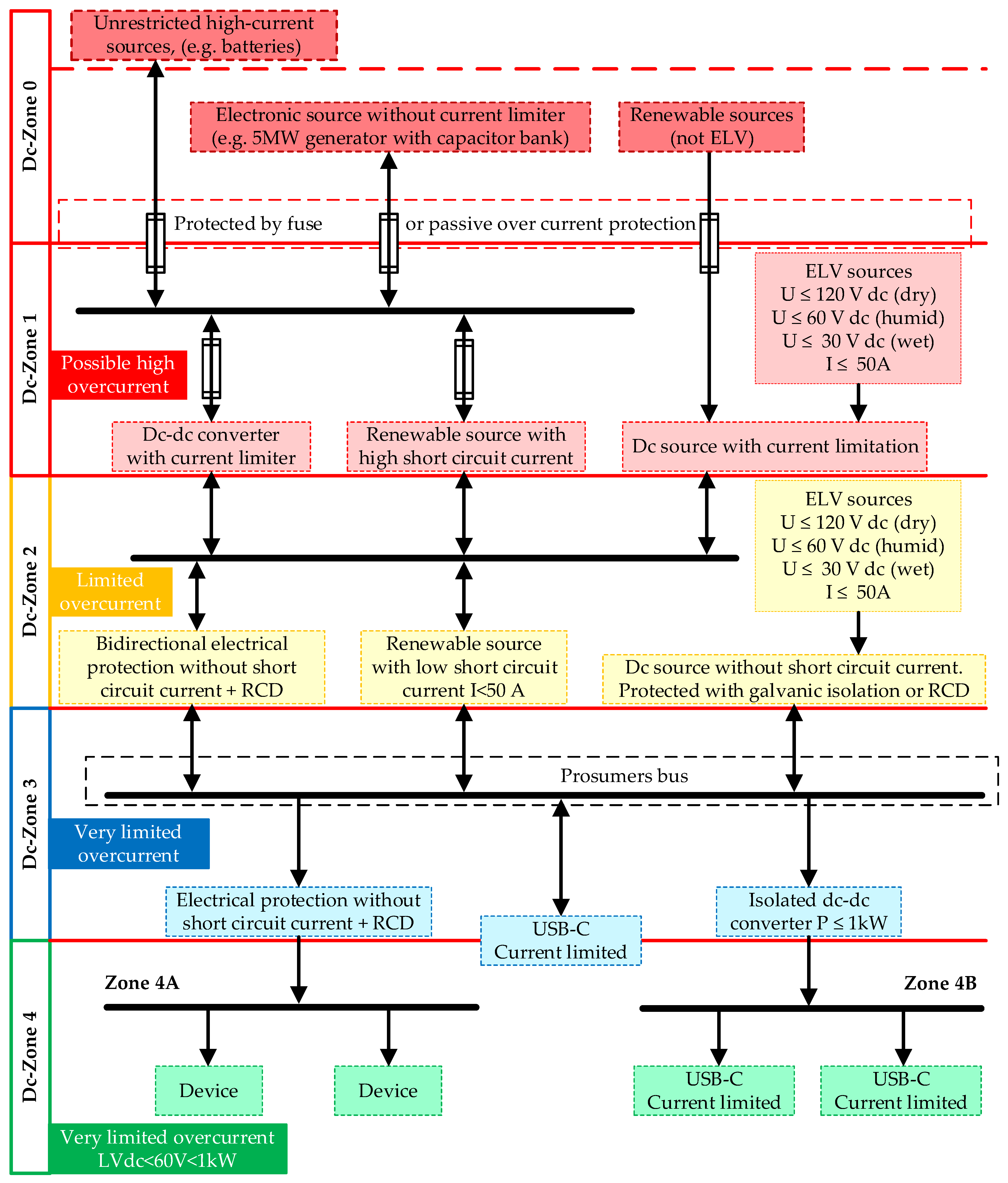
2. Protection and Safety in the DC Microgrid

Although DC microgrids have advantages, such as higher efficiency, without a proper protection system, they will face problems and will not be practical. DC system protection is different from that of an AC system. There are many active sources in the DC system, and each of these sources has a different power level that should be considered in the comprehensive protection system. In case of a fault in the DC microgrid, the DC current fault increases suddenly, and since it does not have a zero crossing, it is not possible to cut it easily; it needs extra equipment [29]. Therefore, from the protection point of view, several aspects should be considered. In recent years, only a few studies have focused on the protection of DC systems [30,31,32,33,34,35,36,37,38,39,40]. Due to the lack of necessary standards and sufficient experience, the DC system is still developing at a slow pace. As mentioned, the DC microgrid can operate independently or in the grid-connected mode and work bi-directionally. These operation modes also introduce more challenges to the protection system. The diagnosis of high impedance faults and issues related to grounding and the ground current are other concerns that should be considered [28]. In the DC system, the short circuit current depends on the source current. Some sources, such as batteries, have a high-rated current and, subsequently, a high short-circuit current, and others, such as PV, have a low short-circuit current. It should also be pointed out that the DC microgrid is decentralized, and each production operates independently. All of these points make the protection operation more complicated. Therefore, a risk classification according to voltage and current level and protection type is recommended in NPR 9090 [41,42].
The NPR 9090 standard includes parts that are intended to describe classification, protection, and grounding in low-voltage DC systems. According to the hazardous level, this classification is divided into five classes from zone 0 (high risk) to zone 4 (low risk). Figure 2 shows this classification. According to each zone and the level of voltage and current, different protection and safety requirements are defined.
As can be seen in Figure 2, unprotected resources, including batteries, grids, large solar power plants, synchronous machines, etc., are placed in zone 0. The characteristics of this zone are a relatively high capacity, the absence of protection, and a current limiter.
In Zone 1, the sources have short-circuit protection, and several sources could also be the case. The voltage level is less than 1500 V, and extra low voltage (ELV) can be less than 120 V.
Zone 2 also has short-circuit protection, with the difference that the short-circuit current level is limited (lower). Other characteristics of this zone are bidirectional operation, a current of less than 50 A for each device, and the use of the residual current device (RCD).
Production and consumption can exist in Zone 3. The voltage level of the line to the ground can be a maximum of 400 V line-to-ground and line-to-line 800 V. The overload current is limited, and the maximum current for each device is 50 A.
In Zone 4, only consumers are present, and it is also called a safe zone. The maximum voltage level is the same as in Zone 3, and all types of consumers with a current of less than 50 A are present in the zone only as consumers.
Based on this classification, the protection method should be chosen according to each zone. As mentioned in this standard, it is possible to ignore zones 2 and 3. However, attention should be paid to the current limits of circuit breakers and fuses and the minimum short-circuit current of each zone. In NPR 9090, voltage levels of 350 V and ±350 are suggested. This voltage level is comparable to a single-phase 230 V AC system, and in the line-to-line mode, 700 V can be similar to a three-phase 400 V AC and can also transmit similar power using existing AC cables.
The voltage level in DC microgrids should conform with the power level, length of the cable, and the type of system protection. While in the AC grid, the slight frequency deviation shows the overload or underload, in the DC microgrids, it is the voltage value that determines the underload or overload. Therefore, the voltage level is involved in energy management.

3. Leakage Current in DC Systems

Another important issue in the DC system protection is related to the leakage current. There are two types of leakage current: AC leakage and DC leakage. These leakage currents can cause serious issues or even endanger the safety of personnel. Therefore, it is important to understand how they form and how they can be removed and limited.

3.1. AC Leakage Current

AC leakage current is mostly caused by common mode voltage (CMV). CMV induces a voltage fluctuation with respect to the ground and produces an undesirable leakage current when there is a conduction path. The path of the leakage current is formed through the stray capacitors between the live conductor of equipment (such as PV and batteries, etc.) and their grounded body on the DC side and the filters of the grounded AC grid or stray capacitance of EMI filters [43,44]. The stray capacitance may be intentional (such as in EMI filter capacitors) or unintentional. Examples are spacings on printed boards, insulations between semiconductors and grounded heatsinks, and the primary-to-secondary capacitance of high-frequency isolating transformers.
Figure 3 shows the general condition of creating the leakage current. Due to the presence of stray capacitance (CP) between the DC system and the grid ground, the high-frequency varying CMV can produce a leakage current through the parasitic capacitors and inverter filters connected to terminals 1 and 2 [44].
Differential-mode voltage Vdm is expressed by
V d m = V 1 N V 2 N
which defines the useful current injected into the grid.
Figure 3b illustrates the equivalent circuit of the leakage current, which is defined by the common-mode voltage Vcm:
V c m = V 1 N + V 2 N 2
Using Equations (1) and (2), the paths of high-frequency elements can be extracted. It can be deduced that differential voltage can also include high-frequency elements, which is effective in creating leakage current. These additional high-frequency elements from Vdm can be written as Vcm−dm in Equation (3).
V c m d m = V d m . L 2 L 1 2 ( L 2 + L 1 )
In the asymmetric condition of the output inductances (L1 not equal to L2), the differential voltage can also affect the CMV and can lead to extra leakage current. In this case, the total high-frequency CMV can be written as Vtcm as Equation (4).
V t c m = V c m + V d t o c = V 1 N + V 2 N 2 + V 1 N V 2 N 2 L 2 L 1 ( L 2 + L 1 ) .
If L1 = 0 or L2 = 0, Vtcm is simplified by
V t c m = V c m + V d t o c = V 1 N + V 2 N 2 + V 1 N V 2 N 2 = V 1 N
V t c m = V c m + V d t o c = V 1 N + V 2 N 2 V 1 N V 2 N 2 = V 2 N
When the DC–AC converter has an asymmetrical inductor configuration (L1 = 0 or L2 = 0), the sufficient condition to cancel the leakage current is that the terminal voltage V1N or V2N keeps constant. If L1 = L2, Vtcm is simplified by
V t c m = V 1 N + V 2 N 2 = V c m ( L 1 = L 2 )
Then, in the symmetrical inductor, the total common-mode voltage will be constant and has no high-frequency variation. This is the condition to cancel the AC leakage current.

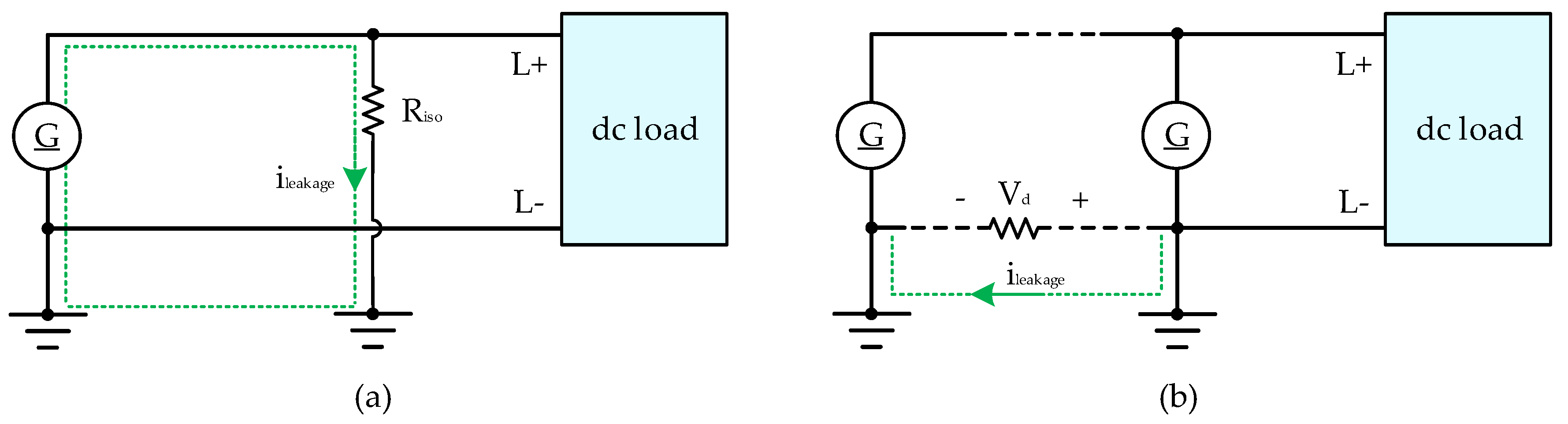
3.2. DC Leakage Current

Besides the AC leakage current, the DC leakage current is the DC current passing through the insulation resistance of the conductor [24,44,45,46,47] or in situations where there is a potential difference between the grounds of the DC system. The DC leakage caused by the insulation resistance is usually insignificant compared to the AC leakage. The insulation resistance of the conductor decreases over time or due to humidity and dust, and this can increase the DC leakage current. As mentioned, to eliminate the AC leakage current, CMV should be fixed. In this case, the parasitic capacitor is open-circuited. But still, a constant voltage falls on the insulation resistance, and the DC leakage current passes through the insulation resistance and the grounds of the system. The value of the DC leakage current can easily be calculated by Ohm’s law, as in Equation (8). But the point is in the estimation method of insulation resistance. Some methods for testing and estimating insulation resistance have been reviewed in the literature [39,48].
i d c = V c o n d u c t o r G n d R i s o
Figure 4 shows a simple representation of two modes of creating DC leakage current in a DC system. In the first case, the leakage current passes through the insulation resistance of the conductor and the ground of the DC system. The path of the leakage current is shown by the dashed line in Figure 4a. For the second case, as mentioned earlier, the DC system is decentralized and has several resources. To have an effective grounding, usually, each source has a separate ground. As shown in Figure 4b, the DC leakage current, in this case, is caused by the voltage drop in the current-carrying conductor (due to the resistance of the conductor) and the grounds of the two sources. The path of the leakage current can also be seen in this case.
Based on the standard IEC-60950 for the leakage current, the value of the total leakage current should be lower than 3.5 mA for a non-handheld device to ensure that the current is very low and cannot harm the person who touches the case of the device. In the case of a handheld device, this current should be lower than 0.25 mA [49]. Also, the injected DC current into the AC grid should not be greater than 0.5 percent of the nominal current [50].
Until now, many structures and control methods have been provided to eliminate or reduce the leakage current. One of the factors that has a direct effect on the leakage current is the way of grounding at the DC or AC system, especially at the connection point of the DC system to the AC grid. In the following, different states of grounding and leakage current will be investigated in different states.

4. Grounding in the AC System
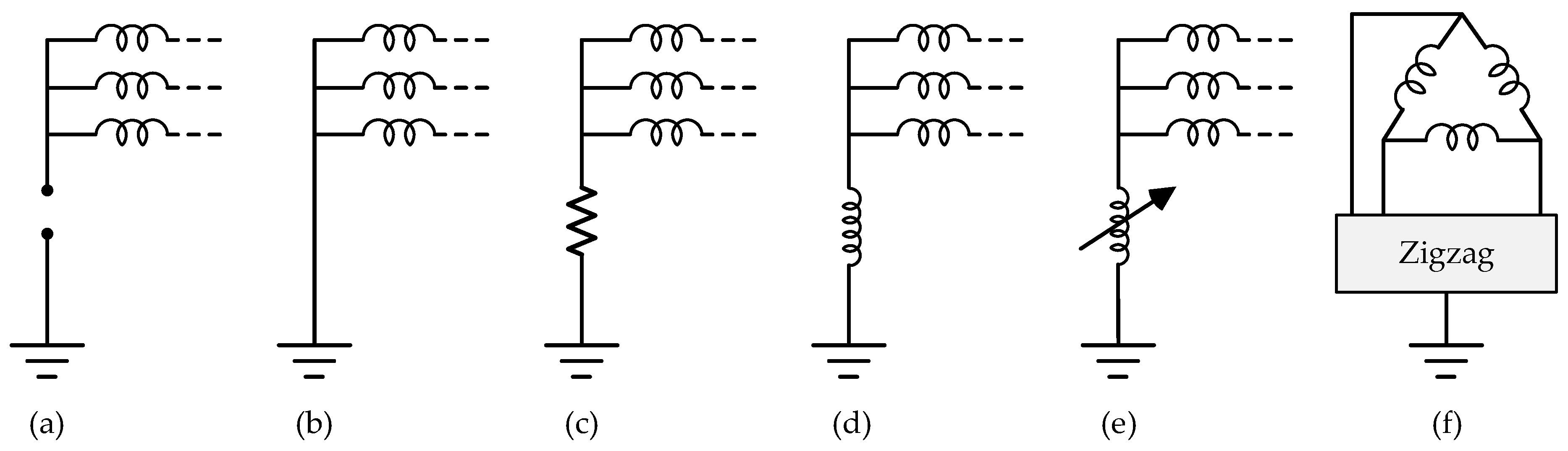
Though DC grounding has its own features and requirements, it is not possible to consider it without consideration of AC grid grounding because of the possible coupling with AC. Therefore, it is helpful to review the different types and configurations of grounding methods in the AC system. In this part, grounding in the AC system is briefly reviewed.
The primary purpose of using earth in AC systems is to protect the personnel and equipment, prevent overvoltage due to any imbalance, etc. In the AC system, the neutral point of the transformer/generator is connected to the earth in different ways, and regarding the way of connection, different configurations can be defined. Each of these methods and configurations has advantages and disadvantages, and the best option should be used according to the conditions (power level and protection system) [51].

4.1. Grounding Type

As mentioned, the earthing of AC systems is usually performed through the neutral point in the Y connection of the transformer or generator. The different states of connecting the neutral point of the transformer/generator to the earth are shown in Figure 5. Table 1 summarizes the basic features of these methods.

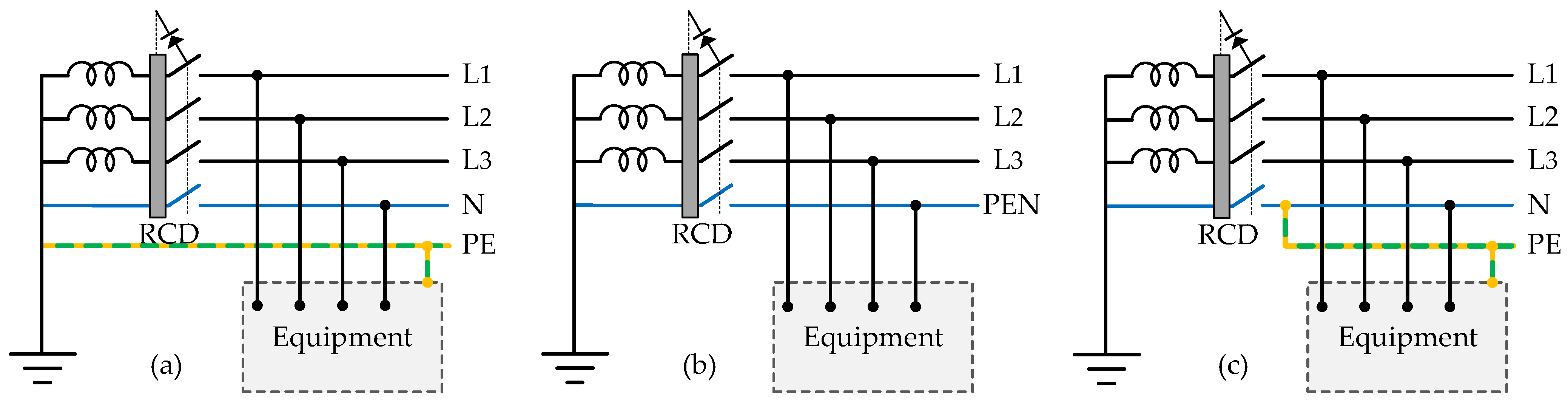
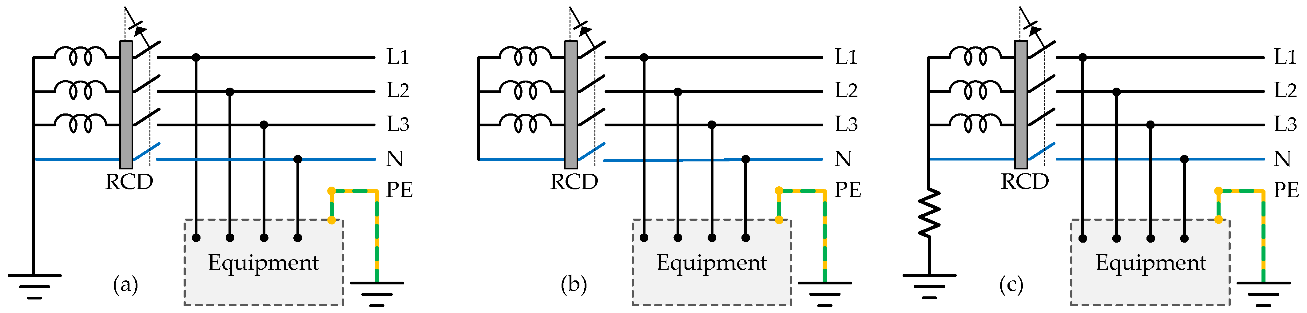
4.2. Grounding Configurations

In the distribution low-voltage grid, different configurations are provided according to the ground of the neutral point of the transformer/generator and the way of the ground on the consumption (building) side. By considering different grounding types in Figure 4 and whether there is an earth connection on the transformer/generator side or not, based on IEC 60364, different configurations can be defined as TN, TT, and IT [6,53]. It should also be mentioned that in the protection and grounding system, a protective earth (PE) conductor is also considered to connect the enclosure of the equipment to the earth. In case the equipment is exposed to the electric potential for any reason, the PE conductor connects this potential to the ground and prevents shock to the human body.
In the TN mode, the neutral point of the transformer is connected directly to the earth. In this case of single-phase loads, the neutral conductor (N) and the protective earth conductor (PE), which is connected to the body of the equipment, are connected to the earth on the transformer side. In the case of TN-S, N, and PE, conductors are separately connected to the earth of the transformer. If a common conductor is used for the N and PE conductors, it is called the TN-C model. In some cases, on the load side, the PE and N conductors are used separately, and on the transformer side, it is combined, which in this case is called TN-C-S. Figure 6 shows different cases of TN configuration for AC systems.
In the TT connection, the neutral point in Y of the transformer is directly connected to the earth, and on the load side, the body of the equipment is connected to the ground through the local earth. In this case, the two grounds are independent of each other. This model of grounding is very suitable for eliminating EMC interference.
In the IT mode, the neutral point of the transformer is not connected to the earth but only on the load side; the body of the equipment is connected to the local earth through the protective ground. In this method, in case of a fault, the system has a higher capacity, and the relays do not work immediately.
High resistance grounding (HRG) can be considered another AC grounding configuration, and when the resistance value is infinite, it is the same as in IT. As compared to the IT configuration, using the HRG method can reduce overvoltages caused by faults and make fault detection easier. Also, in comparison to solidly grounded, the HRG method reduces high fault current and its damages [54].
Figure 7 shows the configurations of TT, IT, and HRG. Table 2 compares the advantages and disadvantages of various types of grounding configurations in the AC system.
It is worth mentioning that the residual current device (RCD) protector shown in the Figures consists of a core on which the phase and neutral conductors are wrapped, and it works based on the magnetic field. If the system works properly and there is no leakage current, the phase and neutral currents are equal and opposite to each other. In such a case, the magnetic field produced by each conductor is equal, has opposite directions, and, finally, has zero output.
In case of current leakage due to any reason (for example, the contact of the human body with the phase), the neutral current will be lower than the phase current. In this case, the resulting field in the core will not be zero, and it will generate a voltage in the existing coil in the core so that the command to disconnect the circuit is applied. It has the same function in the three-phase mode. The problem with RCD is that if there is a connection or leakage in the phase and neutral at the same time, it will not be able to detect the fault.

5. Grounding in DC Microgrids

Despite the advantages of DC microgrids, including flexibility in integration with renewable sources and higher efficiency, it requires high protection. The issue of protection in the DC system is still one of the challenges, and the grounding solution has a direct impact on protection aspects. In this regard, to solve the challenges of the DC system, it is important to provide proper grounding to be able to detect the fault in time and protect personnel and equipment along with disconnection circuits to remove the fault. Therefore, grounding configuration plays an important role in protection systems. The purpose of grounding in microgrids is to protect personnel and equipment, detect ground faults, and reduce stray currents [25].
Before addressing the grounding in the DC systems, the general configuration of the DC system should be described; a DC system can be provided based on two conductors or three conductors. In a two-conductor structure with positive and negative poles, the negative line is usually connected to the earth. When there is a middle point (M) either in two or three conductor cases, the middle line will be earthed. Figure 8 shows these structures. It should be noted that although PEL and PEM carry current, they are not active conductors.
In the case of using a three-conductor structure, line-to-line or line-to-ground with half voltage can be used to feed loads, and this gives redundancy and more flexibility to the configuration. However, in this structure, the voltage balance between the lines to the ground can be challenging, and it needs to be addressed [55].

5.1. Grounding Types

Various methods have been proposed for grounding means in DC systems [26]. Figure 9 shows the general connection states for a unipolar case. These methods include the following states: ungrounded (floating), solidly grounded, high resistor grounded, diode grounded, and thyristor grounded. In the case of bipolar configuration, these devices will be connected to the middle point.
Each of these types of grounding gives a unique feature to the protection system. At low voltage levels, ungrounded mode is usually recommended [27]. In this case, the common mode voltage cannot be too high to harm personnel or equipment. If a single line-to-ground (LG) fault occurs, the system can continue to operate without problems. But if a ground fault is the case in both lines, it will cause a line-to-line (LL) fault and will cause serious damage [56].
In the solid ground device, one of the conductors is connected to the earth directly (in the unipolar case, it is usually the negative pole, and in the bipolar, the middle point). The advantage of this method is the quick detection of the fault current. However, when a fault is detected, the system is unable to continue, and the functioning stops. Corrosion is also unavoidable due to the existence of stray currents in a path without impedance [57]. Other methods also have general features between these two modes. In the ungrounded case, there is no path for current, and in the solidly grounded method, the ground current is high. The high resistance method can limit the fault current, and subsequently, it will prevent the failure of equipment. On the other hand, the operation of the system does not stop during the fault [35].
In the diode ground type, the negative pole is connected to the ground using diode(s). Under normal operating conditions, the system will be ungrounded, and this will reduce leakage currents. In case of a fault or transient condition, when the voltage applied to the diodes exceeds the permissible threshold, the diode conducts, and the system changes to the grounded type. Using a thyristor in the ground path also has the same function as the grounded diode type. The only difference is that by using a thyristor, there will be an active control on its conduction so that the system can be changed from ungrounded to grounded based on a preset threshold [25]. Table 3 summarizes the advantages and disadvantages of each method for grounding devices [25,58,59].
Voltage level and grounding method have a direct impact on safety in the DC system [60]. The types of grounding devices presented for the unipolar structure can be applied to the bipolar structure, and grounding is performed through the middle point. Grounding based on the middle point is a highly recommended solution in the DC system grounding [61]. By middle-point grounding at high-voltage levels, in case of a fault or electric shock on a person, the voltage on the body will be half of the nominal voltage [35,62,63]. This itself can be a form of protection.

5.2. Grounding Configurations in DC Microgrids

Similar to an AC power system, there are different configurations of earthing in the DC systems [33,41,63]. These configurations are TN, IT, and TT configurations. TN configuration can be divided into TN-S, TN-C, or a combination, such as TN-S-C. TN systems are typically connected to the earth through a low impedance path, and in this method, detection of the line fault is easy to implement.
While in TN configuration, there is one ground for the source side and load side, in TT systems, there are two separated earths for each side. Like TN, in TT configuration, fault detection is easy, and this method is a good solution for EMC mitigation. As different from TN systems, in IT systems, there is no earth on the source side. In this case, the fault current is very low, and fault detection is not an easy task. It requires separate measuring equipment, including measuring insulation conditions [39]. Figure 10, Figure 11, Figure 12 and Figure 13 show the different configurations of grounding for unipolar and bipolar modes in the DC system. Table 4 compares the different features of these methods.
It should be added that the TN-S-C, which is the combination of TN-S and TN-C configuration, can also be considered, as in some parts, the PE wire is separate, and in other parts, it is implemented jointly.
Regarding these configurations and their general characteristics in the table, the following consideration can be made:
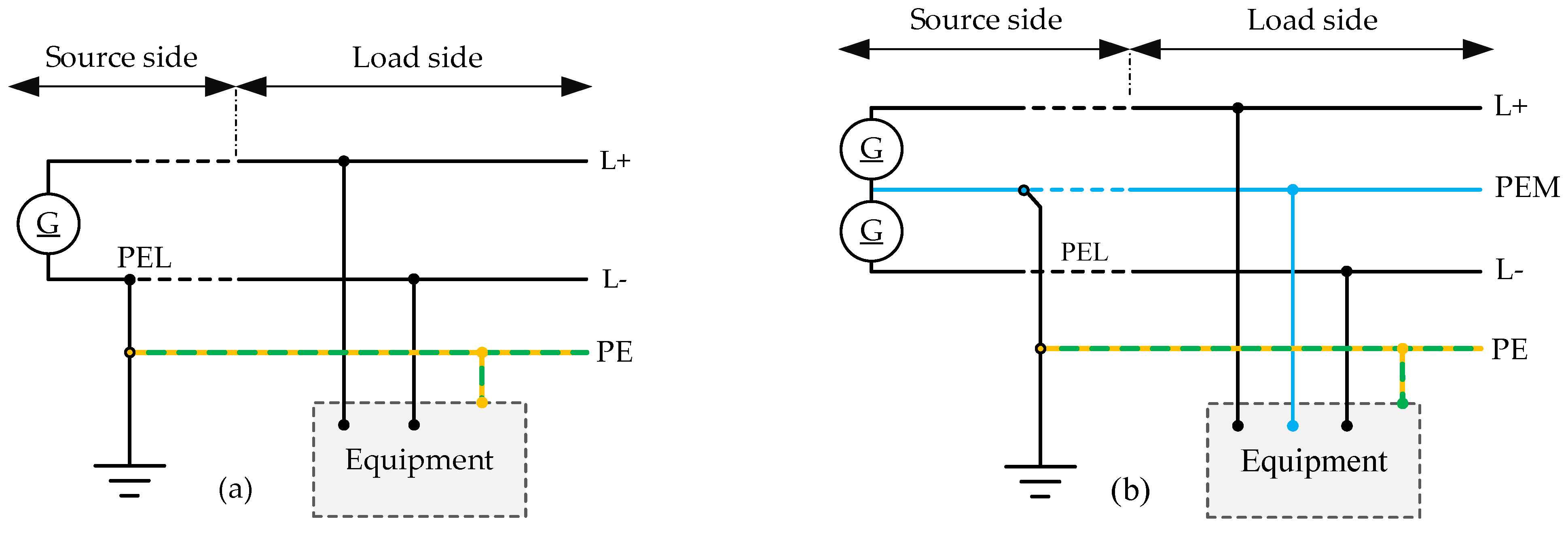
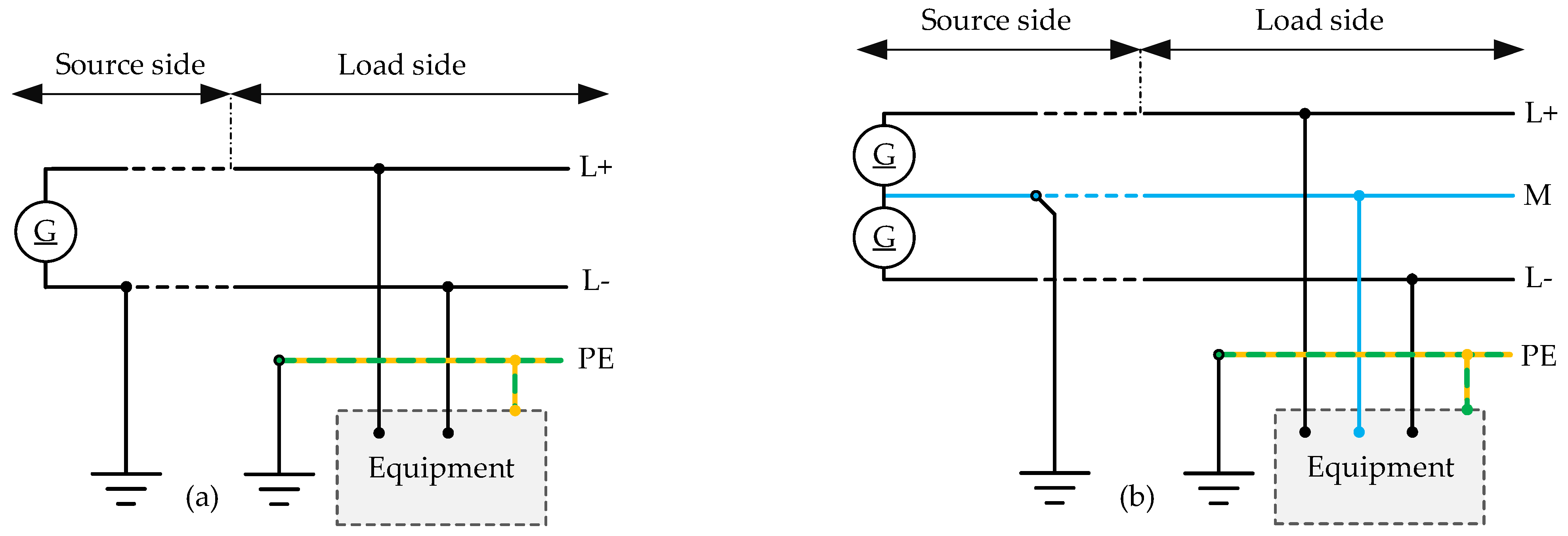
  • In the TN-C grounding mode, if the PEL or PEM wire is loose or has a weak connection, the body and metal parts of the equipment will be under line voltage. Therefore, regardless of the type of function, the TN-C structure should not be used in DC systems;
  • In the TT mode, the resistance of the two ground paths limits the fault current. Therefore, if the body comes into contact with the line with potential and electric shock, short-circuit protection cannot be used as protection against electric shock. Neither is overcurrent protection a suitable option for protection against electric shock due to its slow response time;
  • On the other hand, the use of the IT structure is usually preferred due to the continuity of operation in the event of a fault. This structure is suitable for skilled and trained personnel because it is not easy to detect and fix errors in this structure. The IT structure is also far from touch safety due to the presence of capacitors in EMC filters and existing cables and the creation of capacitive coupling with the ground;
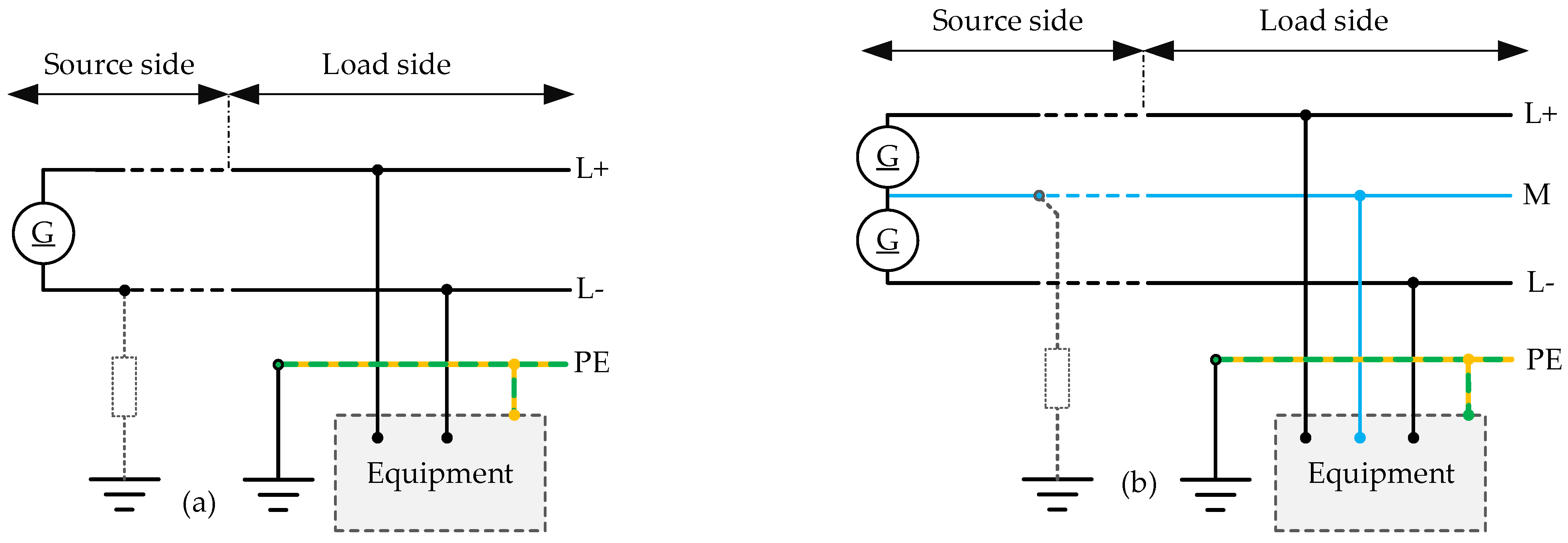
  • Based on the above, the risk classification in Figure 2, and the types of ground structures, the TN-S grounding structure is preferred in zones 1 to 3 and 4a;
  • Systems in DC zone 4B are usually implemented as IT systems in practice because of the USB-C connection.

5.3. Impact of Grounding on the DC Leakage Current

As discussed in the leakage current section, part of the leakage current is related to the DC leakage current. Using common grounding methods, this DC leakage current will flow, and it has adverse effects such as corrosion in metal and concrete parts or injection into the AC grid. In the case of solid ground, for instance, the voltage on the conductors will be fixed. In this case, due to the constant voltage on the ungrounded conductors, the DC leakage current can pass through the insulation resistance and the ground of the system. Also, as mentioned previously (Figure 4b), when there are several sources and grounds in the DC system, the DC leakage current can flow between different grounds.
To solve this problem, several capacitive grounding methods have been proposed, which can greatly reduce or eliminate DC current despite the existence of low impedance grounding on the DC side.
The first solution, which is shown in Figure 14a, uses capacitors and anti-parallel diodes in the ground path [41]. The capacitor is like a short circuit for high-frequency components, and it creates a low-impedance path and will be an open circuit for DC components. Passing the DC leakage current through diodes also requires overcoming the forward voltage of series diodes.
Another similar structure shown in Figure 14b is the use of a capacitor in parallel with Zener diodes [64]. In this case, the Zener diodes are used to avoid a high number of diodes in series. Based on the pre-defined values, the Zener diode can be chosen. In this case, by creating a low-impedance path for high-frequency components, AC and transient current will pass, while there is no path in the ground structure for the DC component.
A similar solution to remove and limit the DC leakage current introduced in [65] is shown in Figure 14c. This grounding structure consists of an R, L circuit parallel to the capacitor. This structure also has a capacitive path that has low impedance at high frequencies and a resistive path to prevent the DC current from passing through. This grounding network is also designed in a way to have a low equivalent impedance and, subsequently, a low voltage in a wide range.
In these capacitive solutions, the design of the components should be such that it prevents the passage of the DC leakage current. In Figure 14a,b, it should be performed through the design of the diode forward voltage value (Figure 14a) and the Zener voltage value (Figure 14b). For Figure 14c, it should also be performed through the design of resistance and an inductor.
The design of the capacitor should be such that it can have very low impedance for high-frequency components. Otherwise, the high-frequency components will pass through the diode or resistor/inductor path, and due to the voltage drop in these paths, the voltage of the other conductor will fluctuate. This will create another path for the leakage current through the stray capacitor of the other conductor(s).

5.4. Grounding Configuration for Several Decentralized Sources

Having several decentralized sources is one of the characteristics of the DC system. As mentioned previously, the use of a grounding TN-S configuration is preferred in the DC system. However, with several decentralized sources, the existence of one earth point cannot be enough due to a long distance and the resistance of the conductor, which affect the grounding system. In such cases, near any source, earthing will be implemented. Again, according to Figure 4b, having several grounds will cause the DC leakage current due to the voltage drop on the conductor. On the other hand, a solid grounding in different points would result in DC ground currents flow due to the difference in the neutral potential. This can cause corrosion and problems associated with the DC leakage current.
To solve this problem, grounding with capacitor networks is used as described earlier (Figure 13) [59,64]. In these grounding networks, due to the very low impedance of the capacitor for high-frequency elements, high-frequency and transient elements pass through the capacitor and act like solid ground. Meanwhile, DC currents cannot pass through these grounding networks. It should also be added that in the case of the presence of several grounds, only one of the sources can have a solid ground, and the rest of the sources should use capacitive grounding to prevent the leakage of DC currents through the grounds.
Regarding Figure 14, one method is to use anti-parallel diodes and capacitors in the ground connection path of the sources [41]. As long as the voltage applied to them is low, these diodes prevent leakage current and, in case of a fault, show normal behavior. Therefore, in this case, two modes, TN-S-CD and TN-S-CDD, are proposed. Figure 15 shows this solution.
In the first case, one source is directly connected to the ground and the other through the diode–capacitor network. In the second case, all sources are connected to the ground through the diode–capacitor network. The use of these modes is applicable for zones 2 and 3 in Figure 2, where the current of sources is limited. In this case, the components should be designed according to the maximum fault current. Using this mode for zones 0 and 1 requires a lot of accurate calculations to determine the maximum fault current for component design.

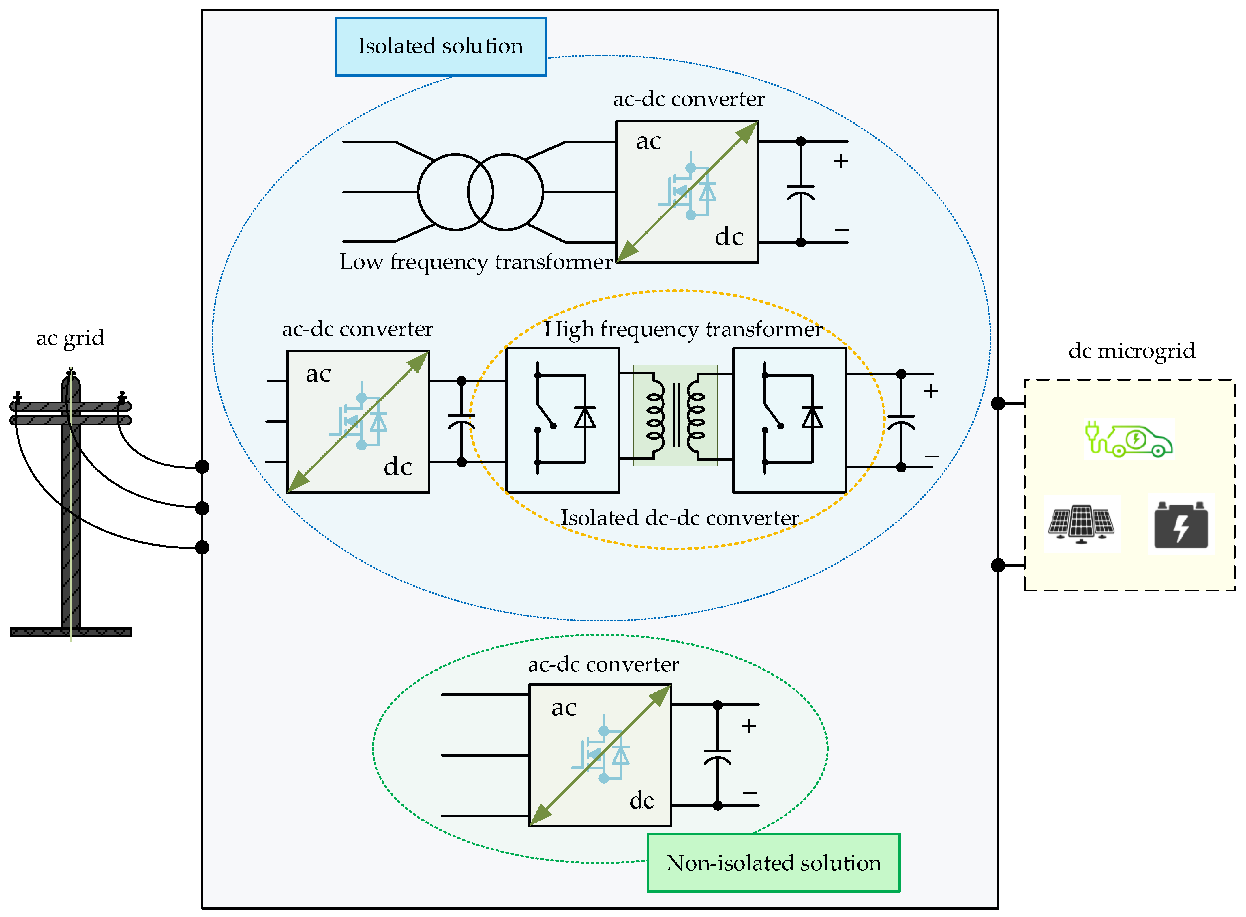
6. Grounding in the Connection Point of the DC Microgrid to the AC Grid

Although in some cases, DC micro/nanogrids can be designed for the off-grid mode in relation to the AC grid, in most cases, they should be connected to the main AC grid to improve the reliability of the electricity supply. Regarding the dominance of the AC grid from the generation, transmission, and distribution sectors, DC microgrids should be connected to the existing AC grid and should interact power with that for self-balancing. In this connection, protection, safety, and grounding methods should be considered on both sides [52,66]. Different configurations of grounding for pure AC and pure DC systems were discussed in previous parts. But at the point where the DC system is connected to the AC system, some aspects should be considered, and the protection method should be designed according to the grounding structure on both sides. At high power and voltage levels, isolation between DC and AC is mandatory to guarantee reliability and safety. In the LVDC, galvanic isolation is supposed to be recruited, but it is not obligatory. In the isolated mode, the grounding method on each side is independent of the other side, and the type of grounding is selected according to the above-mentioned configurations in the AC and DC system grounding.
Figure 16 shows a simplified connection point in the isolated case, while both sides have the grounding near the connection point as DC and AC sources.
The way of grounding has a direct effect on the leakage current. Due to the use of an AC–DC interface converter in all situations, leakage currents can be seen passing through different paths. In this section, the aim is to investigate the path of the possible leakage current in different states of connecting the DC system to the AC grid.

6.1. Isolated Case

In the case of high-frequency isolation, the important point is the existence of a stray parasitic capacitor between the primary and secondary of the high-frequency transformer CiW (interwinding capacitor). In different studies, different methods have been presented to model this capacitor, which is in the picofarad range [67,68]. Stray capacitors in parallel to insulation resistance are used here for a high-frequency transformer.
Two cases for grounding a DC microgrid are considered. The leakage current can flow between the AC grid and the DC system through the stray capacitor and the insulation resistance of the primary and secondary transformer, as demonstrated in Figure 17 and Figure 18.
Figure 17a shows the first condition when the DC microgrid is grounded at a negative point. For this configuration, since the ground on the DC side is at the negative point, a bias voltage proportional to the DC side voltage will be added to the equivalent circuit. Therefore, in this case, the leakage current may have a DC component. Figure 17b shows the equivalent circuit for the leakage current paths in this connection type.
Figure 18a shows the case where the DC microgrid has middle-point grounding. Figure 18b shows the simplified equivalent common-mode circuit. Due to the middle-point grounding on the DC side, there will be no bias voltage in the equivalent circuit (bias voltage sources will cancel each other out). In this case, there is only a common-mode voltage source, which can lead to high-frequency AC leakage current in this case.
In the case of using a low-frequency transformer, the AC grid is completely isolated, and there is no significant AC leakage current component between DC and AC grids.
The path of the DC leakage current is the same due to the theoretical presence of insulation resistance in parallel to this inter-winding capacitor. At the middle-point grounding in the DC side, insulation resistance will not have a significant impact on the DC leakage current. But at the negative-point grounding in the DC side, insulation resistance in the AC side causes a DC component in the total leakage current.
If the secondary side of the transformer and the DC system are both without grounding (or IT grounding), then there will be no path for the leakage current due to the absence of ground. Although, in this case, the leakage current is eliminated, this method is not recommended because of protection and fault detection problems.

6.2. Non-Isolated Case

To increase the efficiency and reduce the cost, volume, and weight, the connection without isolation and solving the issues related to safety and protection in this connection point can be a focus of future research and engineering considerations.
At the same time, the absence of isolation applies a significant limitation on the grounding possibilities on both sides. Depending on the condition of the switches, a direct electrical path can be created through the grounds on both sides. Although the presence of filters in the current path prevents short circuits, high-amplitude, high-frequency currents can pass through two grounds.
The obvious solution in the case of a non-isolated connection is that only one side should be grounded. This means having an IT configuration on the AC side in case the DC side should be grounded, or if grounding in the AC side is mandatory, the DC side should be ungrounded [6,69,70,71]. Table 5 shows different possible solutions for grounding at the connection point in non-isolated cases. As can be seen in this table, when there is grounding on the AC side (TN and TT), the only possible solution on the DC side is an ungrounded case. On the other hand, for the IT case, the DC side can be grounded at the negative or middle point or even remain ungrounded.
The best solution for the non-isolated connection of DC microgrids to the AC grids can be the use of common-ground structures [43,72,73,74,75,76,77,78,79]. In this case, considering that the negative pole of the DC system and the neutral of the AC grid are directly connected to each other, a similar or even asymmetrical grounding method can be used for both sides. In the common-ground structure, the common-mode voltage on the DC negative and the AC neutral is clamped to zero, and their stray capacitors are bypassed. Therefore, the AC leakage current can be eliminated. The DC leakage current can also pass through insulation resistance ground on the DC side system. To solve this, a TN-S-CD type of connection (Figure 15) should be used on the DC side. Figure 19 shows the general view of this solution.

7. Conclusions

LVDC is increasing and developing in the distribution sector. However, there are no sufficient standards and studies in the field of DC system protection and grounding. All types of grounding methods in the DC system and at the connection point of the DC to the AC grid were examined, and their advantages and disadvantages were analyzed. For any structure at the connection point, the DC and the AC leakage current path was shown. The following conclusions can be highlighted:
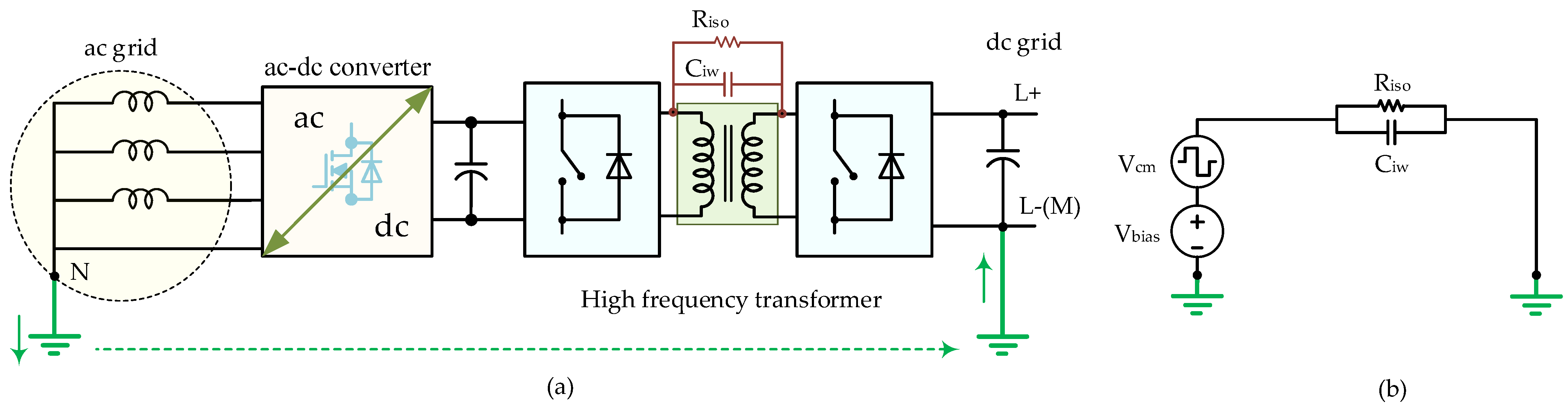
  • In the connection with high-frequency isolation, there is still leakage current in different parts, and in the case of having ground in the AC side (TN or TT), it can be injected from the DC side to the AC grid through the stray inter-winding capacitor between the primary and secondary side of the transformer. A low-frequency transformer eliminates this pass completely;
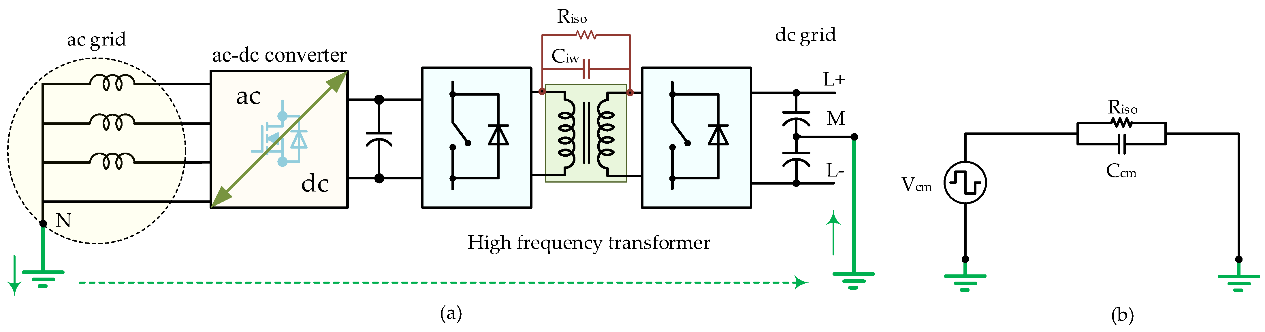
  • In both high-frequency and low-frequency isolation, a DC component in the leakage current can be created by DC voltage bias between the middle (or negative) point of the DC system and the neutral point of the AC system. In order to eliminate this, the configurations where there is no voltage bias between the neutral point of the AC system and the middle point of the DC system are recommended;
  • Grounding based on the middle point based on the TN-S-CD type is a highly recommended solution in the DC system grounding. In addition to fault or minimization of electric shock, it eliminates the DC leakage current between the AC and the DC system;
  • A non-isolated common-ground solution for interlinking DC and AC grids can be considered as an alternative cost-effective solution where the leakage current between the AC and the DC grid can be completely eliminated.
Further research can focus on the analysis of common-ground structures that have higher capabilities, such as high power range and higher output quality in bi-directional operation to be used at the connection point. In addition, practical solutions to reduce or eliminate the leakage current at the connection point, as well as methods for fault detection according to the grounding configuration, are required.

Funding

This project has received funding from the European Union’s Framework Programme for Research and Innovation Horizon 2020 (2014–2020) under the Marie Skłodowska-Curie Grant Agreement No. 955614 and by the Estonian Research Council grant PRG675. The authors are partially supported by Junta de Extremadura and “ERDF A way of making Europe” through Project IB20165.

Conflicts of Interest

The authors declare no conflict of interest.

References

  1. Available online: https://energy.ec.europa.eu/topics/renewable-energy/renewable-energy-directive-targets-and-rules/renewable-energy-targets_en#the-2030-targets (accessed on 1 November 2023).
  2. Li, P. Energy storage is the core of renewable technologies. IEEE Nanotechnol. Mag. 2008, 2, 13–18. [Google Scholar] [CrossRef]
  3. Hamidieh, M.; Ghassemi, M. Microgrids and Resilience: A Review. IEEE Access 2022, 10, 106059–106080. [Google Scholar] [CrossRef]
  4. Najafzadeh, M.; Ahmadiahangar, R.; Husev, O.; Roasto, I.; Jalakas, T.; Blinov, A. Recent Contributions, Future Prospects and Limitations of Interlinking Converter Control in Hybrid AC/DC Microgrids. IEEE Access 2021, 9, 7960–7984. [Google Scholar] [CrossRef]
  5. Dragičević, T.; Lu, X.; Vasquez, J.C.; Guerrero, J.M. DC Microgrids—Part II: A Review of Power Architectures, Applications, and Standardization Issues. IEEE Trans. Power Electron. 2015, 31, 3528–3549. [Google Scholar] [CrossRef]
  6. Kumar, D.; Zare, F.; Ghosh, A. DC Microgrid Technology: System Architectures, AC Grid Interfaces, Grounding Schemes, Power Quality, Communication Networks, Applications, and Standardizations Aspects. IEEE Access 2017, 5, 12230–12256. [Google Scholar] [CrossRef]
  7. Gelani, H.E.; Dastgeer, F.; Nasir, M.; Khan, S.; Guerrero, J.M. Ac vs. dc distribution efficiency: Are we on the right path? Energies 2021, 14, 4039. [Google Scholar] [CrossRef]
  8. Sahoo, S.K.; Sinha, A.K.; Kishore, N.K. Control techniques in AC, DC, and hybrid AC–DC microgrid: A review. IEEE J. Emerg. Sel. Top. Power Electron. 2017, 6, 738–759. [Google Scholar] [CrossRef]
  9. Chen, M.; Ma, S.; Wan, H.; Wu, J.; Jiang, Y. Distributed Control Strategy for DC Microgrids of Photovoltaic Energy Storage Systems in Off-Grid Operation. Energies 2018, 11, 2637. [Google Scholar] [CrossRef]
  10. Aluisio, B.; Bruno, S.; De Bellis, L.; Dicorato, M.; Forte, G.; Trovato, M. DC-microgrid operation planning for an electric vehicle supply infrastructure. Appl. Sci. 2019, 9, 2687. [Google Scholar] [CrossRef]
  11. Carvalho, E.L.; Blinov, A.; Chub, A.; Emiliani, P.; de Carne, G.; Vinnikov, D. Grid Integration of DC Buildings: Standards, Requirements and Power Converter Topologies. IEEE Open J. Power Electron. 2022, 3, 798–823. [Google Scholar] [CrossRef]
  12. NPapanikolaou; Kyritsis, A.; Loupis, M.; Tzotzos, C.; Zoga, E. Design Considerations for Single-Phase Line Frequency Transformers Applied at Photovoltaic Systems. IEEE Power Energy Technol. Syst. J. 2015, 2, 82–93. [Google Scholar] [CrossRef]
  13. Hannan, M.A.; Ker, P.J.; Lipu, M.S.H.; Choi, Z.H.; Rahman, M.S.A.; Muttaqi, K.M.; Blaabjerg, F. State of the Art of Solid-State Transformers: Advanced Topologies, Implementation Issues, Recent Progress and Improvements. IEEE Access 2020, 8, 19113–19132. [Google Scholar] [CrossRef]
  14. She, X.; Huang, A.Q.; Burgos, R. Review of Solid-State Transformer Technologies and Their Application in Power Distribution Systems. IEEE J. Emerg. Sel. Top. Power Electron. 2013, 1, 186–198. [Google Scholar] [CrossRef]
  15. Ryu, M.-H.; Kim, H.-S.; Baek, J.-W.; Kim, H.-G.; Jung, J.-H. Effective Test Bed of 380-V DC Distribution System Using Isolated Power Converters. IEEE Trans. Ind. Electron. 2015, 62, 4525–4536. [Google Scholar] [CrossRef]
  16. IEEE Std 1547a-2020; IEEE Standard for Interconnection and Interoperability of Distributed Energy Resources with Associated Electric Power Systems Interfaces--Amendment 1: To Provide More Flexibility for Adoption of Abnormal Operating Performance Category III. (Amendment to IEEE Std 1547-2018). IEEE: Piscataway, NJ, USA, 15 April 2020; pp. 1–16. [CrossRef]
  17. Rivera, S.; Lizana, F.R.; Kouro, S.; Dragičević, T.; Wu, B. Bipolar DC Power Conversion: State-of-the-Art and Emerging Technologies. IEEE J. Emerg. Sel. Top. Power Electron. 2021, 9, 1192–1204. [Google Scholar] [CrossRef]
  18. Dey, S.; Bussa, V.K.; Singh, R.K. Transformerless Hybrid Converter With AC and DC Outputs and Reduced Leakage Current. IEEE J. Emerg. Sel. Top. Power Electron. 2019, 7, 1329–1341. [Google Scholar] [CrossRef]
  19. Buticchi, G.; Barater, D.; Lorenzani, E.; Franceschini, G. Digital Control of Actual Grid-Connected Converters for Ground Leakage Current Reduction in PV Transformerless Systems. IEEE Trans. Ind. Inform. 2012, 8, 563–572. [Google Scholar] [CrossRef]
  20. TOliveira, R.; Silva, W.W.A.G.; Seleme, S.I.; Donoso-Garcia, P.F. PLL-Based Feed-Forward Control to Attenuate Low-Frequency Common-Mode Voltages in Transformerless LVDC Systems. IEEE Trans. Ind. Appl. 2019, 55, 3151–3159. [Google Scholar] [CrossRef]
  21. Qiu, J.; He, Y.; Lei, C.; Jiao, Q.; Liu, J. An Improved LMSVM Method for Leakage Current Suppression and Neutral-Point Voltage Control in Transformerless NPC Three-Level Inverters. IEEE J. Emerg. Sel. Top. Power Electron. 2022, 10, 3100–3113. [Google Scholar] [CrossRef]
  22. Zhou, L.; Gao, F.; Xu, T. Implementation of Active NPC Circuits in Transformer-Less Single-Phase Inverter With Low Leakage Current. IEEE Trans. Ind. Appl. 2017, 53, 5658–5667. [Google Scholar] [CrossRef]
  23. Iturriaga-Medina, S.; Martinez-Rodriguez, P.R.; Escobar-Valderrama, G.; Vazquez-Guzman, G.; Langarica-Cordoba, D.; Rosas-Caro, J.C.; Sosa-Zuniga, J.M.; Mayo-Maldonado, J.C. Leakage-Ground Currents Compensation in a Transformerless HB-NPC Topology Using a DC-Link-Tied LC Filter for Photovoltaic Applications. IEEE J. Emerg. Sel. Top. Power Electron. 2022, 10, 4725–4737. [Google Scholar] [CrossRef]
  24. Escobar, G.; Martinez-Rodriguez, P.R.; Iturriaga-Medina, S.; Mayo-Maldonado, J.C.; Lopez-Sarabia, J.; Micheloud-Vernackt, O.M. Mitigation of Leakage-Ground Currents in Transformerless Grid-Tied Inverters via Virtual-Ground Connection. IEEE J. Emerg. Sel. Top. Power Electron. 2019, 8, 3111–3123. [Google Scholar] [CrossRef]
  25. Mohammadi, J.; Ajaei, F.B.; Stevens, G. Grounding the DC Microgrid. IEEE Trans. Ind. Appl. 2019, 55, 4490–4499. [Google Scholar] [CrossRef]
  26. Pourmirasghariyan, M.; Zarei, S.F.; Hamzeh, M. DC-system grounding: Existing strategies, performance analysis, functional characteristics, technical challenges, and selection criteria-a review. Electr. Power Syst. Res. 2022, 206, 107769. [Google Scholar] [CrossRef]
  27. Park, J. Ground fault detection and location for ungrounded DC traction power systems. IEEE Trans. Veh. Technol. 2015, 64, 5667–5676. [Google Scholar] [CrossRef]
  28. Beheshtaein, S.; Cuzner, R.M.; Forouzesh, M.; Savaghebi, M.; Guerrero, J.M. DC Microgrid Protection: A Comprehensive Review. IEEE J. Emerg. Sel. Top. Power Electron. 2019. [Google Scholar] [CrossRef]
  29. Rahimpour, S.; Husev, O.; Vinnikov, D. Design and Analysis of a DC Solid-State Circuit Breaker for Residential Energy Router Application. Energies 2022, 15, 9434. [Google Scholar] [CrossRef]
  30. Park, J.-D.; Candelaria, J. Fault Detection and Isolation in Low-Voltage DC-Bus Microgrid System. IEEE Trans. Power Deliv. 2013, 28, 779–787. [Google Scholar] [CrossRef]
  31. Xu, L.; Guerrero, J.M.; Lashab, A.; Wei, B.; Bazmohammadi, N.; Vasquez, J.C.; Abusorrah, A. A Review of DC Shipboard Microgrids—Part II: Control Architectures, Stability Analysis, and Protection Schemes. IEEE Trans. Power Electron. 2021, 37, 4105–4120. [Google Scholar] [CrossRef]
  32. Sheikh, A.A.; Wakode, S.A.; Deshmukh, R.R.; Ballal, M.S.; Suryawanshi, H.M.; Mishra, M.K.; Kumar, S. A Brief Review on DC Microgrid Protection. In Proceedings of the 2020 IEEE First International Conference on Smart Technologies for Power, Energy and Control (STPEC), Nagpur, India, 25–26 September 2020; pp. 1–6. [Google Scholar] [CrossRef]
  33. Zhang, L.; Tai, N.; Huang, W.; Liu, J.; Wang, Y. A review on protection of DC microgrids. J. Mod. Power Syst. Clean Energy 2018, 6, 1113–1127. [Google Scholar] [CrossRef]
  34. Mohanty, R.; Pradhan, A.K. Protection of DC and hybrid AC-DC microgrids with ring configuration. In Proceedings of the 2017 7th International Conference on Power Systems (ICPS), Pune, India, 21–23 December 2017; pp. 607–612. [Google Scholar] [CrossRef]
  35. Noritake, M.; Iino, T.; Fukui, A.; Hirose, K.; Yamasaki, M. A study of the safety of the DC 400 V distribution system. In Proceedings of the INTELEC 2009—31st International Telecommunications Energy Conference, Incheon, Republic of Korea, 18–22 October 2009; pp. 1–6. [Google Scholar] [CrossRef]
  36. Husev, O.; Matiushkin, O.; Vinnikov, D.; Roncero-Clemente, C.; Kouro, S. Novel Concept of Solar Converter With Universal Applicability for DC and AC Microgrids. IEEE Trans. Ind. Electron. 2021, 69, 4329–4341. [Google Scholar] [CrossRef]
  37. Husev, O.; Vinnikov, D.; Kouro, S.; Blaabjerg, F.; Roncero-Clemente, C. Dual-Purpose Converters for DC or AC Grid as Energy Transition Solution: Perspectives and Challenges. IEEE Ind. Electron. Mag. 2023, 2–13. [Google Scholar] [CrossRef]
  38. Vygoder, M.; Milton, M.; Gudex, J.D.; Cuzner, R.M.; Benigni, A. A Hardware-in-the-Loop Platform for DC Protection. IEEE J. Emerg. Sel. Top. Power Electron. 2020, 9, 2605–2619. [Google Scholar] [CrossRef]
  39. Liu, Y.-C.; Lin, C.-Y. Insulation fault detection circuit for ungrounded DC power supply systems. In Proceedings of the 2012 IEEE, SENSORS, Taipei, Taiwan, 28–31 October 2012; pp. 1–4. [Google Scholar] [CrossRef]
  40. Salomonsson, D.; Soder, L.; Sannino, A. Protection of Low-Voltage DC Microgrids. IEEE Trans. Power Deliv. 2009, 24, 1045–1053. [Google Scholar] [CrossRef]
  41. Standard NPR 9090:2018; DC Installations for low Voltage. Royal Dutch Standardization Institute (NEN): Delft, The Netherlands, 2018.
  42. Blinov, A.; Roasto, I.; Chub, A.; Emiliani, P.; Vinnikov, D. Electric Power Management and Control in DC Buildings—State-Of-The-Art and Emerging Technologies. In Power Quality: Infrastructures and Control; Springer: Singapore, 2023; pp. 67–96. [Google Scholar]
  43. Li, W.; Gu, Y.; Luo, H.; Cui, W.; He, X.; Xia, C. Topology Review and Derivation Methodology of Single-Phase Transformerless Photovoltaic Inverters for Leakage Current Suppression. IEEE Trans. Ind. Electron. 2015, 62, 4537–4551. [Google Scholar] [CrossRef]
  44. Gu, Y.; Li, W.; Zhao, Y.; Yang, B.; Li, C.; He, X. Transformerless Inverter with Virtual DC Bus Concept for Cost-Effective Grid-Connected PV Power Systems. IEEE Trans. Power Electron. 2012, 28, 793–805. [Google Scholar] [CrossRef]
  45. Khan, M.N.H.; Forouzesh, M.; Siwakoti, Y.P.; Li, L.; Kerekes, T.; Blaabjerg, F. Transformerless Inverter Topologies for Single-Phase Photovoltaic Systems: A Comparative Review. IEEE J. Emerg. Sel. Top. Power Electron. 2019, 8, 805–835. [Google Scholar] [CrossRef]
  46. Demetriou, A.; Buxton, D.; Charalambous, C.A. Stray Current DC Corrosion Blind Spots Inherent to Large PV Systems Fault Detection Mechanisms: Elaboration of a Novel Concept. IEEE Trans. Power Deliv. 2016, 33, 3–11. [Google Scholar] [CrossRef]
  47. Dimitriou, A.; Charalambous, C.A. DC Interference Modeling for Assessing the Impact of Sustained DC Ground Faults of Photovoltaic Systems on Third-Party Infrastructure. IEEE Trans. Ind. Electron. 2018, 66, 2935–2945. [Google Scholar] [CrossRef]
  48. Wu, Y.; Zhang, P. A Novel Online Monitoring Scheme for Underground Power Cable Insulation Based on Common-Mode Leakage Current Measurement. IEEE Trans. Ind. Electron. 2022, 69, 13586–13596. [Google Scholar] [CrossRef]
  49. IEC 60950 Standard. Available online: https://webstore.iec.ch/publication/4020 (accessed on 1 November 2023).
  50. IEEE Std 1547-2018; IEEE Standard for Interconnection and Interoperability of Distributed Energy Resources with Associated Electric Power Systems Interfaces. (Revision of IEEE Std 1547-2003). IEEE: Piscataway, NJ, USA, 6 April 2018; pp. 1–138. [CrossRef]
  51. Mohammadi, J.; Ajaei, F.B.; Stevens, G. Grounding the AC Microgrid. IEEE Trans. Ind. Appl. 2019, 55, 98–105. [Google Scholar] [CrossRef]
  52. Yang, J.; Xiao, X.; Su, W.; Si, X.; Zhang, J.; Zhang, X. Comparison of Grounding Modes of MMC-Based Flexible DC Distribution System. IEEE Access 2021, 9, 19696–19706. [Google Scholar] [CrossRef]
  53. IEC 60364-1; Low-Voltage Electrical Installations—Part 1: Fundamental Principles, Assessment of General Characteristics, Definitions. International Electrotechnical Commission: Geneva, Switzerland, 2005.
  54. Sattari, P.; Panetta, S. High-Resistance Grounding Design for Industrial Facilities: Providing Continuity of Service in Complex Distribution Systems. IEEE Ind. Appl. Mag. 2019, 26, 18–27. [Google Scholar] [CrossRef]
  55. Lopez-Sarabia, J.; Valderrama, G.E.; Martinez-Rodriguez, P.R.; Iturriaga-Medina, S.; Mayo-Maldonado, J.C.; Puerto-Flores, D.D. DC-Link Capacitors’ Voltage Balance in an HB-NPC Five-Level Grid-Tied Inverter via the Common-Mode Control Component. IEEE J. Emerg. Sel. Top. Power Electron. 2021, 10, 3242–3255. [Google Scholar] [CrossRef]
  56. Valdes, M.; Papallo, T.; Premerlani, B. Finding fault—Locating a ground fault in low-voltage, high-resistance grounded systems via the single-processor concept for circuit protection. IEEE Ind. Appl. Mag. 2007, 13, 24–30. [Google Scholar] [CrossRef]
  57. Paul, D. DC traction power system grounding. IEEE Trans. Ind. Appl. 2002, 38, 818–824. [Google Scholar] [CrossRef]
  58. Mobarrez, M.; Fregosi, D.; Bhattacharya, S.; Bahmani, M.A. Grounding architectures for enabling ground fault ride-through capability in DC microgrids. In Proceedings of the 2017 IEEE Second International Conference on DC Microgrids (ICDCM), Nuremburg, Germany, 27–29 June 2017; pp. 81–87. [Google Scholar] [CrossRef]
  59. Naghizadeh, M.; Farjah, E.; Ghanbari, T.; Pourgharibshahi, H.; Andani, M.T. Efficient Grounding Method for DC Microgrid with Multiple Grounding Points. In Proceedings of the 2018 Clemson University Power Systems Conference (PSC), Charleston, SC, USA, 4–7 September 2018; pp. 1–6. [Google Scholar] [CrossRef]
  60. Karppanen, J.; Kaipia, T.; Mattsson, A.; Nuutinen, P.; Kim, J.; Cho, J.; Peltoniemi, P.; Partanen, J.; Lana, A.; Pinomaa, A. Effect of Voltage Level Selection on Earthing and Protection of LVDC Distribution Systems. In Proceedings of the 11th IET International Conference on AC and DC Power Transmission, Birmingham, UK, 10–12 February 2015; pp. 1–8. [Google Scholar] [CrossRef]
  61. Yang, J.; Fletcher, J.E.; O’Reilly, J. Short-circuit and ground fault analyses and location in VSC-based DC network cables. IEEE Trans. Ind. Electron. 2012, 59, 3827–3837. [Google Scholar] [CrossRef]
  62. Jacobson, B.; Walker, J. Grounding considerations for DC and mixed DC and AC power systems. Naval Eng. J. 2007, 119, 49–62. [Google Scholar] [CrossRef]
  63. Hirose, K.; Tanaka, T.; Babasaki, T.; Person, S.; Foucault, O.; Sonnenberg, B.J.; Szpek, M. Grounding concept considerations and recommendations for 400VDC distribution system. In Proceedings of the 2011 IEEE 33rd International Telecommunications Energy Conference (INTELEC), Amsterdam, The Netherlands, 9–13 October 2011; pp. 1–8. [Google Scholar] [CrossRef]
  64. Mackay, L.; Martinez, K.F.Y.; Vandeventer, E.; Ramirez-Elizondo, L.; Bauer, P. Capacitive grounding for DC distribution grids with two grounding points. In Proceedings of the 2017 IEEE Second International Conference on DC Microgrids (ICDCM), Nuremburg, Germany, 27–29 June 2017; pp. 76–80. [Google Scholar] [CrossRef]
  65. Saleh, S.A.; Kanukollu, S.; Al-Durra, A. Performance Assessment of Frequency Selective Grounding for Grid-Connected Photovoltaic Systems. IEEE Trans. Power Deliv. 2022, 38, 1138–1147. [Google Scholar] [CrossRef]
  66. Zhang, W.; Wei, T.; Chen, Q.; Cui, Y.; Liu, W.; Yang, J. Study on Grounding Modes of AC/DC Hybrid Distribution System. In Proceedings of the 2019 IEEE International Conference on Energy Internet (ICEI), Nanjing, China, 27–31 May 2019; pp. 42–46. [Google Scholar] [CrossRef]
  67. Lu, H.Y.; Zhu, J.G.; Hui, S. Experimental determination of stray capacitances in high frequency transformers. IEEE Trans. Power Electron. 2003, 18, 1105–1112. [Google Scholar] [CrossRef]
  68. Fu, K.; Chen, W.; Lin, S. A general transformer evaluation method for common-mode noise behavior. Energies 2019, 12, 1984. [Google Scholar] [CrossRef]
  69. de Oliveira, T.R.; Bolzon, A.S.; Donoso-Garcia, P.F. Grounding and safety considerations for residential DC microgrids. In Proceedings of the IECON 2014—40th Annual Conference of the IEEE Industrial Electronics Society, Dallas, TX, USA, 29 October–1 November 2014; pp. 5526–5532. [Google Scholar] [CrossRef]
  70. Zhang, D.; Cao, D.; Huber, J.; Everts, J.; Kolar, J.W. Non-Isolated Three-Phase Current DC-Link Buck-Boost EV Charger with Virtual Output Midpoint Grounding and Ground Current Control. IEEE Trans. Transp. Electrif. 2023. [Google Scholar] [CrossRef]
  71. Roncero-Clemente, C.; Husev, O.; Matiushkin, O.; Gutierrez-Escalona, J.; Barrero-Gonzalez, F.; Vinnikov, D.; Strzelecki, R. Feasibility Study of Three-Phase Modular Converter for Dual-Purpose Application in DC and AC Microgrids. IEEE J. Emerg. Sel. Top. Power Electron. 2023. [Google Scholar] [CrossRef]
  72. Lee, S.S.; Lim, C.S.; Siwakoti, Y.P.; Lee, K.-B. Single-Stage Common-Ground Boost Inverter (S2CGBI) for Solar Photovoltaic Systems. In Proceedings of the 2019 IEEE Energy Conversion Congress and Exposition (ECCE), Baltimore, MD, USA, 29 September–3 October 2019; pp. 4229–4233. [Google Scholar]
  73. Lee, S.S.; Yang, Y.; Siwakoti, Y.P. A Novel Single-Stage FiveLevel Common-Ground-Boost-Type Active Neutral-Point-Clamped (5L-CGBT-ANPC) Inverter. IEEE Trans. Power Electron. 2021, 36, 6192–6196. [Google Scholar] [CrossRef]
  74. Vosoughi, N.; Hosseini, S.H.; Sabahi, M. A New Single-Phase Transformerless Grid-Connected Inverter With Boosting Ability and Common Ground Feature. IEEE Trans. Ind. Electron. 2019, 67, 9313–9325. [Google Scholar] [CrossRef]
  75. Shahsavar, T.H.; Kurdkandi, N.V.; Husev, O.; Babaei, E.; Sabahi, M.; Khoshkbar-Sadigh, A.; Vinnikov, D. A New Flying Capacitor-Based Buck–Boost Converter for Dual-Purpose Applications. IEEE J. Emerg. Sel. Top. Ind. Electron. 2023, 4, 447–459. [Google Scholar] [CrossRef]
  76. Azizi, M.; Rahimpour, S.; Husev, O.; Veligorskyi, O. Back-to-Back Energy Router Based on Common-Ground Inverters. In Proceedings of the 2023 IEEE 17th International Conference on Compatibility, Power Electronics and Power Engineering (CPE-POWERENG), Tallinn, Estonia, 14–16 June 2023; pp. 1–6. [Google Scholar] [CrossRef]
  77. Barzegarkhoo, R.; Siwakoti, Y.P.; Vosoughi, N.; Blaabjerg, F. Six-Switch Step-Up Common-Grounded Five-Level Inverter With Switched-Capacitor Cell for Transformerless Grid-Tied PV Applications. IEEE Trans. Ind. Electron. 2020, 68, 1374–1387. [Google Scholar] [CrossRef]
  78. Husev, O.; Kurdkandi, N.V.; Marangalu, M.G.; Vinnikov, D.; Hosseini, S.H. A New Single-Phase Flying Inductor-Based Common Grounded Converter for Dual-Purpose Application. IEEE Trans. Ind. Electron. 2023, 70, 7913–7923. [Google Scholar] [CrossRef]
  79. Barzegarkhoo, R.; Lee, S.S.; Siwakoti, Y.P.; Khan, S.A.; Blaabjerg, F. Design, Control, and Analysis of a Novel Grid-Interfaced Switched-Boost Dual T-Type Five-Level Inverter With Common-Ground Concept. IEEE Trans. Ind. Electron. 2021, 68, 8193–8206. [Google Scholar] [CrossRef]
Figure 1. Different solutions for connecting a DC microgrid to an AC grid.
Energies 16 07747 g001
Figure 2. Safety and risk classification in the DC system proposed in NPR 9090 [41,42].
Energies 16 07747 g002
Figure 3. (a) Leakage current path through a parasitic capacitor on the DC side and grounded AC side. (b) Equivalent circuit of the leakage current.
Energies 16 07747 g003
Figure 4. The DC leakage current is created through (a) the insulation resistance of the conductor and the ground of the system and (b) the potential difference created by the conductor resistance in the live conductor and grounds of the system.
Energies 16 07747 g004
Figure 5. AC grid grounding type: (a) ungrounded; (b) solidly grounded; (c) resistance grounded; (d) reactance grounded; (e) adjustable reactance grounded; (f) zigzag connection grounded [51].
Energies 16 07747 g005
Figure 6. Configuration of TN grounding schemes in the AC system: (a) TN-S; (b) TN-C; (c) TN-S-C.
Energies 16 07747 g006
Figure 7. Configuration of grounding schemes in the AC system: (a) TT; (b) IT; (c) HRG.
Energies 16 07747 g007
Figure 8. Different configurations in DC systems: (a) unipolar without a middle point; (b) bipolar, and (c) unipolar.
Energies 16 07747 g008
Figure 9. DC microgrid grounding devices: (a) ungrounded; (b) solidly grounded; (c) resistance grounded; (d) diode grounded; (e) thyristor grounded [26].
Energies 16 07747 g009
Figure 10. TN-S grounding in the DC system with (a) two conductors (unipolar) and (b) three conductors (bipolar).
Energies 16 07747 g010
Figure 11. TN-C grounding in the DC system with (a) two conductors (unipolar) and (b) three conductors (bipolar).
Energies 16 07747 g011
Figure 12. TT grounding in the DC system with (a) two conductors (unipolar) and (b) three conductors (bipolar).
Energies 16 07747 g012
Figure 13. IT grounding in the DC system with (a) two conductors (unipolar) and (b) unipolar three conductors (bipolar) (in this case, the system can be connected to the earth via a sufficiently large resistance.)
Energies 16 07747 g013
Figure 14. Grounding solution for minimizing the DC leakage current: (a) anti-parallel diodes and capacitor solution in [41]; (b) Zener diode and capacitor solution in [64]; (c) RLC circuit solution in [65] (In the case of bipolar form, these grounding networks will be connected to the middle point).
Energies 16 07747 g014
Figure 15. Grounding multiple sources in the bipolar DC system: (a) TN-S-CD; (b) TN-S-CDD.
Energies 16 07747 g015
Figure 16. When both AC and DC sides have grounding, there will be a direct electric path for current to pass between sides.
Energies 16 07747 g016
Figure 17. Leakage current path of high-frequency isolated connection for the unipolar DC system: (a) general circuit; (b) simplified equivalent common-mode circuit.
Energies 16 07747 g017
Figure 18. Leakage current path of high-frequency isolated connection for the bipolar DC system (grounded at the middle point): (a) general circuit; (b) simplified equivalent common-mode circuit.
Energies 16 07747 g018
Figure 19. Connection through a common-grounded inverter and elimination of the leakage current path.
Energies 16 07747 g019
Table 1. Advantages and disadvantages of different grounding types in AC grids [52].
Grounding DeviceAdvantages and Disadvantages
Ungrounded
-
No cost
-
Continuity of operation in case of fault
-
Hard fault detection
Solidly grounded
-
Simple grounding
-
No voltage fluctuation problem
-
High fault current
-
Easy fault detection
Resistance grounded
-
Relatively simple
-
Limited fault current
-
Ability of continuity of operation in case of fault
-
Large installation area
Reactor grounded
-
Absorbs reactive power and weakens AC voltage regulation ability
-
High cost
-
Large installation area
-
DC bias component in AC side voltage
Zigzag Grounded
-
High reliability
-
Low reactive power consumption and small installation area
Table 2. Comparison of different configurations of AC grounding.
TopologyAdvantageDisadvantage
TN
-
Effective for EMC
-
Fast fault detection
-
Large fault current and inability to continue operation
TT
-
Effective for EMC
-
Fast fault detection
-
Large fault current and inability to continue operation
IT
-
Availability under fault conditions
-
Large transient voltage may occur during the ground fault
HRG
-
Availability under fault conditions, Limited fault current, reduced overvoltage stress in TT.
-
It is difficult to determine the resistance value
-
Causes power losses
Table 3. Advantages and disadvantages of different grounding types in the DC microgrid [25].
Grounding
Type
AdvantageDisadvantage
Ungrounded
-
Low LG fault current
-
Power supply continuity at an LG fault
-
Minimized DC leakage current and corrosion
-
Simple implementation
-
No grounding power loss
-
No grounding cost
-
Difficult to detect and locate LG faults
-
Possibility of significant system damage under LG fault evolving to LL fault
-
Sensitive to noise and disturbances
-
Small leakage currents cause large common-mode voltage
-
Requires high insulation level
Solidly Grounded
-
High safety due to low common mode voltage
-
Limited overvoltages
-
Low insulation level requirement
-
Low grounding cost
-
Easy to detect and clear LG faults
-
Absorbing and filtering disturbances
-
High LG fault current
-
Lower power supply reliability
-
Risk of damage to equipment
-
Interference with communication systems due to larger LG fault currents
High-Resistance Grounded
-
Limiting resonant overvoltages by absorbing the energy of the resonance
-
Low leakage current
-
Low LG fault current
-
Capability to operate under LG faults
-
Power supply continuity
-
High system reliability
-
Greater safety for equipment
-
High overvoltage on the unfaulted line
-
Risk of damage to the system insulation
-
Power supply reliability due to the effects of faults
-
Difficult to detect LG faults
-
Susceptible to noise and disturbances
-
Considerable costs associated with the high-voltage grounding resistors
Low-Resistance Grounded
-
The leakage current and LG fault current levels are high, and the common mode voltage is low
-
Reduced overvoltage at the unfaulted line during the LG fault and low-grounding cost
-
Absorbs and filters disturbances more easily than high-resistance-grounded systems
-
Large LG fault current
-
Disturbances such as switching harmonics, nonlinear loads, and electromagnetic interference can inject currents into the DC system
Diode Grounded
-
Under normal operating conditions, the system is ungrounded, and leakage current is minimized
-
Both the leakage current concern and the common-mode voltage issue are addressed
-
Requiring periodical maintenance as corrosion due to the leakage current is not completely eliminated
Thyristor Grounded
-
Under normal operating conditions, the system is ungrounded, and leakage current is minimized
-
Both the leakage current concern and the common-mode voltage issue are addressed
-
Active control based on preset value
-
Requiring periodical maintenance as corrosion due to the leakage current is not completely eliminated
Table 4. Comparison of different grounding configurations in DC microgrids [28].
Grounding ConfigsSafety of PersonnelSafety of EquipmentContinuity of ServiceEMC
TN-SGood
  • Poor
  • High fault current
Average
  • Excellent
  • Less equipotential problems
  • Requirement to manage devices with high leakage currents
  • High fault current (transient disturbances)
TN-CGood
  • Poor
  • High fault current
Average
  • Poor
  • High fault current (transient disturbances)
TTGood
  • Good
  • Fault current less than a few dozen amperes
Average
  • Good
  • Risk of overvoltage/ voltage imbalance
  • Equipotential problems
  • Requirement to manage devices with high leakage currents
ITGood
  • Very good
  • The fault current is less than a few dozen mA but high for the second fault
Excellent
  • Poor (to be avoided)
  • Risk of overvoltage
Table 5. Different solutions for grounding at the connection point.
AC GNDTN (Any Kind)TTIT
DC GND
Negative point groundedForbiddenForbiddenPossible
Middle point groundedForbiddenForbiddenPossible
UngroundedPossiblePossiblePossible
Disclaimer/Publisher’s Note: The statements, opinions and data contained in all publications are solely those of the individual author(s) and contributor(s) and not of MDPI and/or the editor(s). MDPI and/or the editor(s) disclaim responsibility for any injury to people or property resulting from any ideas, methods, instructions or products referred to in the content.

