Abstract
This paper addresses a crucial omission in the traditional approach to solving the classic economic dispatch problem within microgrids featuring renewable energy sources—the often-neglected frequency disturbances arising from reductions in system inertia. To remedy this, we present an innovative economic dispatch model empowered by nonlinear optimization (NLP), incorporating stringent minimum inertia constraints essential for ensuring system stability over a 24-h horizon. Our approach involves a comprehensive exploration of the intricate relationship between system inertia and frequency stability, culminating in the seamless integration of these inertia constraints into the economic dispatch model. To validate the practicality of our model, we present two distinct scenarios: a base case representing conventional dispatch methodologies and an alternative case that considers the imposition of inertia restrictions. These scenarios are rigorously tested and implemented using the CICGRE TF C6.04 test system. Employing the powerful GAMS platform alongside the NPL model, we successfully solved the dispatch problem. Our results underscore the significance of maintaining system inertia within the 1.54-s threshold proposed by our model, showcasing a tangible reduction in generation costs as a direct outcome of this enhanced approach to economic dispatch. This research advances the understanding of microgrid management and offers a practical solution to enhance system stability and economic efficiency in renewable-energy-powered microgrids.
1. Introduction
Traditionally, energy generation in electrical systems has been based on synchronous generators. These generators contribute a valuable property to the network: inertia. This inertia is derived from the rotating masses of the generators and turbines connected to the electrical system. These rotating masses have the remarkable ability to keep spinning even when their source of motive energy is interrupted. The inertia of the electrical system plays a significant role in the frequency’s behavior immediately after a disturbance. When a disturbance causes a power deficiency, an inertial response releases the kinetic energy stored in the rotating masses of the synchronous machines towards the network. This phenomenon results in the deceleration of the synchronous machines and, consequently, in a decrease in the system frequency. However, as the power grid evolves and more renewable energy sources are incorporated, these sources, typically connected by power electronic devices, need the ability to contribute more to the system inertia, as illustrated in Figure 1.
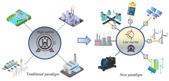
Figure 1.
Evolution of the electrical system.
This phenomenon is considered one of the main challenges when integrating a large number of non-synchronous generators into the network since it compromises the stability of the frequency and its response in transient situations. This approach raises fundamental questions about the amount of inertia available and its role in the future of power grids [1,2,3,4,5,6]. Given this evolution and change in the energy landscape, it is essential to address this challenge and develop solutions that guarantee the stability and reliability of electrical systems.
Despite their significant environmental benefits, the transition to renewable energy sources presents new challenges for electricity system operators. Reducing system inertia is one of these crucial challenges due to the intermittent and unpredictable nature of renewable energy sources. Recent reports and studies have shed light on the growing concern about frequency stability in power grids, mainly due to the lack of inertial response of renewable energy sources. Figure 2 provides a striking visual representation of this decline in inertia in some EU-28 countries during periods where constant generation loss is experienced. This phenomenon, in which the loss of synchronous inertia increases constantly each year, is closely related to the increase in the penetration of renewable energies in the electrical system. This trend raises fundamental questions about how to maintain the stability and reliability of electrical networks in a constantly changing environment. It highlights the urgency of addressing this issue effectively and sustainably [7,8].
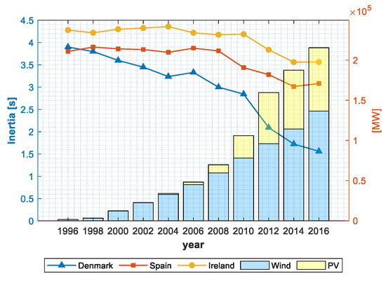
Figure 2.
Evolution of equivalent inertia and installed capacity of renewable resources in EU-28 countries.
In the current context, various innovative strategies are proposed to reduce inertia in electrical systems. One of these outstanding strategies involves using power electronics to control the frequency, which provides the system with a synthetic, emulated, or virtual inertia. This solution represents a fundamental advance in effectively integrating renewable energy sources into the electrical grid, thus mitigating the loss of stability that often accompanies these intermittent sources.
Additionally, research is oriented towards searching for solutions through planning and optimizing electrical networks. Methods are being developed based on optimizing energy dispatch, considering the frequency response and its influence on inertia as a security constraint in the electricity market. Nomenclature describes the abbreviations used in this article.
Literature Review
Several studies have been carried out to analyze the impact of the increase in renewable energies on power systems.
Substantial challenges linked to the large-scale integration of wind generation and its impact on the operational security of power systems were addressed in [9]. Strategies based on unit commitment and economic dispatch have been proposed to address possible deficiencies in synchronous inertia, especially in scenarios of high penetrations of non-synchronous generation. These strategies generate daily unit commitment and economic dispatch (UCED) schedules in the Irish and Northern Ireland electricity systems. These innovative and planning-oriented approaches are crucial to ensure the reliability and efficient operation of electrical systems in a constantly changing environment, driven by the increasing penetration of non-synchronous energy sources such as wind.
In the study referenced in [10], the evaluation of the implications of the incremental growth of renewable generation has been carried out in-depth in regard to its influence on the frequency response in electrical systems. Two fundamental parameters related to the inertial capacity of the system have been examined: the Nadir (which represents the lowest frequency reached) and the ROCOF (which measures the rate of change of frequency). The results reveal that as a greater wind generation capacity is integrated into the grid, the frequency change rate in contingency situations becomes more significant and severe. This analysis also highlights a relevant aspect: the effort necessary to guarantee sufficient inertia in the electrical system entails an additional cost. An endogenous formulation of the unit commitment problem has been used to carry out this evaluation. In this approach, the requirements associated with the frequency response, which include the inertia and ramp speed of the regulator, have been incorporated directly into the optimization problem as constraints, as opposed to an external approach that handles these separate aspects of the main unit commitment optimization problem. This comprehensive approach allows for a deeper understanding of how integrating renewable energy sources impacts the stability and efficient operation of the electrical system.
Ref. [11] investigates how the high penetration of photovoltaic (PV) units affects voltage regulation and power flow in active distribution networks. A multi-objective function defines the nonlinear power flow problem, and the Cuckoo Search (CS) algorithm is applied to solve the OPF problem. The proposed method was tested using the IEEE 123-node test case. A comparison of the results of the PV unit with traditional operation methods shows that locating the PV units in the unbalanced distribution system would lead to better performance.
In [12], a hybrid wind–battery power system (WBS) is used to reduce the influence of the fluctuation of wind energy on the distribution network through a hierarchical control method, the strategy of DNA control. Then, the optimal scheduling model of the active distribution network establishes the control strategy, and the optimal operation of ADN is realized by considering the limitation of reactive power output and reserve capacity in the model. To solve the optimization problem, an adaptive particle swarm algorithm (APSO) is used.
In [13], a two-layer model for economic dispatch in isolated MGs is proposed, in which an MG is considered the lower layer. In contrast, a communication network is considered as the upper layer. Consequently, two sets of control laws are derived from the two subgraphs, where the control laws of the lower layer subgraph generate the balance between supply and demand in the MG, while the control laws of the upper layer subgraph carry out the economic dispatch. Economic operation in MGs can be satisfied only if the agents in the communication network regulate the distributed generators iteratively according to the control laws.
Ref. [14] describes a method to optimize the participation of distributed energy resources (DER) in the primary frequency response through a frequency droop slope design procedure for individual distributed energy resources (DER). In a distribution feeder, they provide a preset primary frequency response at the feeder’s head. The droop slopes are designed so that the DERs respond proportionately to their nominal power values; the approach adopted is based on the optimization and linearizations of the power flow equations to incorporate equity constraints on the physics of power flows within the distribution network.
An innovative approach for optimizing electrical and thermal energy management in a microgrid operating with multiple energy carriers is presented in [15]. This approach’s central objective is minimizing operating costs while ensuring compliance with specific system constraints. The model uses daily forecasts of over 24 h to estimate electrical and thermal loads within the microgrid and electricity generation from wind turbines. These forecasts are obtained through a Monte Carlo simulation, which provides a probabilistic approach to managing uncertainty in operating conditions. Likewise, a real-time demand response program is implemented to adjust non-essential loads efficiently based on price fluctuations. The critical piece in this methodology lies in the minimization of the operating costs of the microgrid through a particle swarm optimization algorithm. This comprehensive approach offers a complete perspective for microgrid management, fusing load, and generation prediction with demand response and cost optimization, significantly contributing to the operational efficiency and profitability of the microgrid in question.
In the study presented in [16], researchers have developed a comprehensive unit commitment formulation that incorporates frequency restrictions, applying it to the operation of the electrical system of the island of Gran Canaria, which has a significant presence of sources of renewable energy. The results obtained reveal that, despite the inclusion of these restrictions, the frequency values remained within the permissible limits, which highlights the effectiveness of this approach in preserving the stability of the system. However, it is essential to note that this improvement in frequency stability has been achieved at the cost of an approximately 13% increase in system operating costs.
Table 1 provides a concise summary of the authors and proposed optimization methodologies in this context, reflecting the diversity and vitality of research efforts in this crucial field. These interdisciplinary approaches represent a significant step towards ensuring the stability and reliability of power grids in a constantly evolving environment.

Table 1.
Existing methodologies to ensure the stability of the electrical system.
Until now, in most studies cited, no simplified procedure analyzes the effect of reduced inertia on the economic dispatch applied to microgrids connected to the grid with a high penetration of renewable energies as a solution to frequency stability. This article presents the formulation of a static economic dispatch model considering the technical constraints of the system components, such as the maximum generation capacities of each renewable energy source, the capacities of the transmission lines, and the voltage limits. In addition, a minimum inertia restriction that the electrical network must maintain is included. The basis for this approach stems from the need to guarantee frequency stability to achieve the optimal management of renewable resources, ensuring the reliability of the electrical system at the lowest cost. The contributions of this work are listed below: (1) a linearized model of the inertia constraint of the system is obtained from the rate of change of the RoCoF frequency and is evaluated with the practical requirements proposed in [7] to determine the minimum inertia of the system. (2) An economic dispatch is implemented with multiple renewable sources: solar photovoltaic (PV), wind turbine (WT), fuel cell (FC), energy storage system (BESS), and Combined Power Generation (CHP). The proposed method is tested with different load demand profiles and generation availability for a 24-h horizon.
The contents of this article are organized into five sections. In Section 2, the notation is presented, and the linearized model of the inertia constraint is obtained. In Section 3, the formulation of the mathematical model of the static economic dispatch of multiple renewable sources connected to the grid with technical and security restrictions is developed. In Section 4, the results of the proposed method using the CIGRE TaskForce C6.04.02 test system are analyzed in detail. In Section 5, conclusions are drawn.
2. Frequency Response
The kinetic energy Ek, of a rotating mass is related to the moment of inertia by:
where ω is the angular velocity of the rotating body. For a cylindrical body rotating about its central axis, the moment of inertia J is:
in this expression, m is the mass, and r is the radius of the cylinder. The inertia of a generator is often described through the inertia constant H. The inertia constant is defined as the stored kinetic energy in [MJ] at synchronous speed ωm, divided by the rated capacity of the machine SG [MV A].
SG is the nominal apparent power of the generator. The inertia constant H is a quantified value related to the kinetic energy of a rotor. It indicates the time interval at which a generator at synchronous speed can provide the same amount of electrical energy as the stored kinetic energy of the rotor [7,17,18,19,20,21].
In traditional power systems, the dynamic behavior of a synchronous machine is based on the oscillation equation, defined as [7,18,19,20]:
where J is the moment of inertia [kg/m2] t is time, ωm is the angular velocity of the synchronous rotor [rad/s], the rotation speed of the magnetic field is , where f0 is the nominal frequency (Hz), Tm and Te are the mechanical and electrical torque of the generator, Pm is the mechanical power supplied by the generator, and Pe is the electrical power demand.
A synchronous machine contributes inertia if it rotates synchronously with the grid, which means that its rotation speed equals the grid frequency [7]. It is important to emphasize that frequency is a global and uniform parameter throughout the electrical system, meaning its value is identical in all interconnected locations. Since the system frequency is intrinsically linked to the speed of the generators connected to the grid, the ability to keep a synchronous machine rotating synchronously with this frequency plays a crucial role in contributing the inertia necessary to ensure the operational stability of the electrical system as a whole.
Equation (4) shows how the system frequency behaves when there is an imbalance between the power input and output. Substituting Equations (1) and (3) in Equation (4) results in another form of the oscillation equation, where the change in kinetic energy in response to an imbalance is described:
Equation (5) shows how an imbalance in the system ( will change the kinetic energy stored in the power system generators. The mechanical power Pm changes very slowly compared to the electrical power Pe, due to the relatively slow response of the governor. Therefore, it can be assumed that the mechanical power is approximately constant initially after a perturbation (). By rearranging Equation (4), under these conditions, it can be observed how the rate of change of frequency (RoCoF) is limited only by inertia just after an imbalance occurs.
Equation (6) shows the inertial response inherent to a synchronous machine directly connected to the grid. The equation indicates how the rate of change of frequency (RoCoF) is inversely proportional to the inertia constant and to the change in electrical power . The negative sign indicates that the power reaction will be of the opposite sign to the change in frequency and, therefore, will oppose the disturbance [7].
The total inertia constant for a power system , can be calculated using Equation (7), below. The equation applies to a system with n units and is based on the weighted sum of the inertia constants for each individual machine i:
where is the nominal apparent power of a machine i. Some approximate values of the inertia constant H for different types of generation units depending on their nominal power are: a 60 MW steam thermal generation unit provides 3.3 s, a 120 MW gas thermal generation unit provides 5.0 s, and a 75 MW hydroelectric generation unit provides 4.0 s [5].
3. Methods and Materials
The methodology used to maintain the inertia of the electrical system within safe levels through the use of online economic dispatch, particularly when renewable energy generation sources are incorporated into a distribution network, is detailed in the flow diagram that is illustrated in Figure 3. This visual representation is essential to understand the decision-making process and resource coordination in real-time, to preserve the operational stability of the electrical system, taking into account the inherent challenges to the intermittency and variability of renewable energy sources.
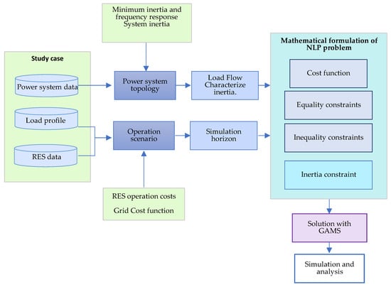
Figure 3.
Proposed methodology.
3.1. Minimum Inertia Levels
Establishing the minimum level of inertia plays a fundamental role in ensuring the safe and stable operation of the electrical system. It is important to note that different regions or system operators may establish other restrictions based on their specific needs to preserve system frequency stability [3,21,22,23,24]. There are several practical requirements that some countries use to determine the minimum inertia of the system. For example, in the Nordic electricity market (NORDIC), the following is used: 48.85 Hz as a set point for frequency-based load shedding (UFLS), 0.5 Hz/s as the frequency change rate allowed (RoCoF), 1.65 GW as the size of the supported contingency, 25 GW as the minimum level of permitted inertia, and 72 GW as the maximum level of electrical demand. On the other hand, the system operator in charge of the electricity market for most of Texas, ERCOT, uses 59.3 Hz for UFLS, 0.5 Hz/s for RoCoF, 2.75 GW of supported contingency, 100 GW as a minimum level of inertia, and 73 GW as the maximum level of electricity demand [7]. The various constraints and criteria illustrate the complexity inherent in managing power system inertia. They highlight the importance of adapting these measures to each region’s or operator’s specific needs and conditions to ensure the power grid’s reliability.
The rate of change of frequency (RoCoF) is considered to evaluate the inertia in this work. The values that ensure system stability range between 0.5 Hz/s to 3 Hz/s. The power change considered for the test case is 0.11 p.u., which corresponds to the worst scenario in which distributed renewable resources have a sudden loss. When evaluating these values in the linear form of the oscillation equation of Equation (6), the minimum values of synchronous inertia are obtained before a change in the electrical power connected to the system in 1.54 s corresponding to an RoCoF of 0.5 Hz/s and in 3.08 s corresponding to an RoCoF de 1.0 Hz/s. The graphical results are presented in part (a) of Figure 4.
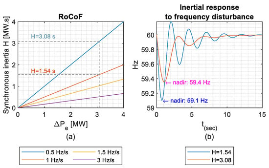
Figure 4.
Frequency response to power disturbance: (a) RoCoF, (b) inertial response to frequency disturbance.
With the minimum inertia obtained, the behavior of the frequency in the event of a power disturbance is evaluated in the differential form of Equation (6). As shown in part (b) of Figure 4, the nadir frequency is 59.1 Hz and 59.4 Hz. These are within safe limits based on the grid code requirements of [7]. The inertia total of the system will depend on the configuration of plants with synchronous inertia that the network has; from [5], the inertia value of the system is assumed to be 3 s, which agrees with the inertia value obtained with a rate of frequency change of 0.5 Hz/s.
3.2. Economic Dispatch Problem Formulation
Some authors propose variants of the economic office regarding formulating the problem and its solution. Its application depends on the context of the situation intended to be solved. Some authors consider restrictions in multiple periods for each hour of the 24-h dispatch time horizon to anticipate future events produced by rapid changes in demand, in the availability of renewable sources, or due to voltage transients. This approach is known as multiperiod optimization. This type of optimization problem can be non-convex, so the solution methods are mainly based on quadratic optimization, interior point methods, and game theory, among others [25,26,27,28,29,30]. Another approach is single-period economic dispatch, also known as static economic dispatch, in which resource availability is scheduled for each hour of a 24-h horizon. Given that the operating costs of the units are generally represented as quadratic functions dependent on the generation level, it is possible to solve the problem using modelling techniques such as mixed-integer quadratic programming (MIQP). Although the solution to this type of problem with commercial software has improved substantially in recent years, it still needs to make it possible to solve real instances. An alternative path corresponds to approximating the problem through some convenient linearization. This makes it possible to use nonlinear programming (NLP) to solve the economic dispatch problem [25,28].
This work focuses on reducing the dispatch of active power produced by renewable energy sources to maintain safe levels of inertia throughout the network. This is achieved by including an inertia constraint in the dispatch of renewable resources so that all network demand is satisfied while maintaining a minimum of inertia provided by the connection to the interconnected system through the slack bus. At the same time, the active and reactive power balance equations are satisfied. In addition, voltage and angle values throughout the network are maintained within acceptable levels. To solve this problem, a simplification is proposed based on the static economic dispatch model. This is because the frequency is a global variable for the entire network; that is, the frequency is the same in all nodes of the electrical grid and varies slightly with significant load changes. Unlike voltage, a variable that differs locally in each node is affected by minimal load changes, and this criterion is adopted to use nonlinear programming (NLP) instead of dynamic programming. Furthermore, to ensure the connectedness of the problem, using linearizations of the cost function of renewable resources RES with the use of Ep. (19) is proposed because since it is a microgrid, the nominal powers of each of the sources are relatively small, resulting in a linear behavior of the operating costs due to the portion of power that is dispatched [31].
In the formulation of the economic dispatch problem, the following assumptions are made:
- A first case arises where all renewable resources must be consumed first, and conventional generators must reduce their generation capacity to give preference to these.
- To evaluate the differences between costs, a second case is proposed where the inertia restriction is included in the economic dispatch.
- None of the renewable resources have synthetic inertia.
- We simplify the model by ignoring the randomness of renewable resources due to the focus of our proposal on reducing the participation of renewable energy in the dispatch. Therefore, an hourly dispatch period is considered over a 24-h horizon in all case studies.
- It is assumed that all renewable energy sources have resources based on 24-h power profiles.
- The system operator dispatches all conventional and renewable generation sources.
- It is considered that the way to control or limit the dispatch of renewable resources is through the diversion or derivation of the power produced for other uses such as heating or storage.
- In the case of the Slack bar and the synchronous generator, a quadratic cost function is considered because in our approach, they are the type of source that predominates in the dispatch.
- In the case of renewable resources, linear cost functions are considered.
3.3. Objective Function
The total cost in Equation (8) is obtained from the sum of the costs of the network operator (Equation (9)) and the costs of the distributed renewable resources (Equation (10)), which are subject to inequality constraints for the balance between generation and demand (Equation (17)), satisfaction of minimum inertia requirements (Equation (18)), operation of the units within their technical limits (Equations (14) and (15)), power flows between nodes (Equations (11) and (12)), bus voltage limits (Equation (13)), and rotor angle limits (Equation (16)). In this formulation, T are the periods under study, Ng is the set of all synchronous generation units, Nr is the set of all RESs, is the power injected by unit g in the period t, is the power injected by unit r in period t, is the cost function of unit g, is the cost function of renewable unit r, is the system demand in period t, and is the minimum inertia reserve required by the system. Inequality restrictions are considered for the limits of the rotor angle, voltage limits in the bars, and balance of active and reactive power in the bars. Nomenclature describes the nomenclature and definition of subscripts, parameters, and variables for the Economic Dispatch Problem Formulation.
4. Simulation and Discussion
The proposed method is applied for testing in the North American configuration of the test system with the integration of Renewable Energy Resources of the CIGRE TaskForce C6.04.02 [32]. The system has 14 nodes, configured in a ring, connected to the infinite bus through two transformers and 15 overhead distribution lines with impedance , to which residential and industrial users are connected.
The system has 15 distributed generation sources with renewable energy; the characteristics and operating costs are indicated in Table 2 and Table 3. The predicted power produced by the RES on each bus indicated in Figure 5b.

Table 2.
Parameters of synchronous units.

Table 3.
Parameters of DER units [32,33,34].
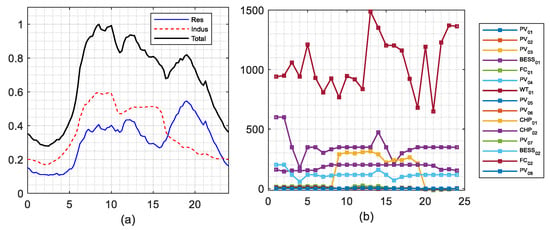
Figure 5.
Forecasted (a) demand and (b) RES generation for CIGRE bus system.
A simplification of the Economic Dispatch Problem is based on the linearization of costs. The procedure is illustrated in Equation (19).
As a scenario for the economic dispatch, the demand profile in Figure 5a with a 24-h horizon is proposed. The maximum demand to serve is 26,426.57 kW. The load is predominantly industrial and occurs at 8:00 a.m.
4.1. Base Case: Priority of Renewable Resources in Energy Dispatch
In the first case study, the maximum RES penetration level is used as a base scenario for comparison. Furthermore, the system inertia reserve requirement is 0, the voltage limits in the bars are at . The optimization problem presented is an NLP nonlinear programming problem; the model has been implemented using GAMS in order to find the operating costs for the given conditions.
The problem is solved, taking a total resolution time of 2.843 s. The objective function is $1,234,856.7 for the maximum demand at 8:00 a.m. and $77,295.0 for the minimum demand at 2:00 a.m.
All distributed generation units with renewable energy sources participate in the dispatch throughout the considered horizon; at the time of maximum demand, 75.8% of the demand is covered by the infinite bus, and at the same time, the DER units dispatch the remaining 11.95% to the maximum of its capacity. At no time are the power limits exceeded, and always, the balance of power demanded is ensured. The thermal unit covers the remaining 12.25% of the energy. In Figure 6b, it can be seen that the most significant contribution of renewable energy is made by the wind turbine, followed by the BESS, CHP, and PV units. Regarding the power balance, it can be seen in Figure 6c that the energy demand represents 94.72% of the energy produced. Therefore, the system losses are equivalent to 5.28%. The minimum demand is 7534.08 kWh.
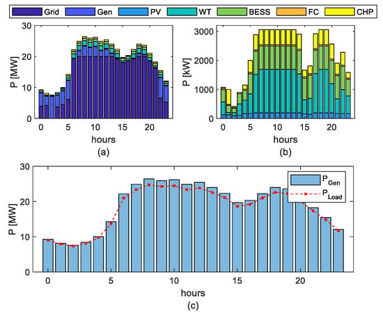
Figure 6.
Power dispatch (a) with maximum RES participation; (b) view of renewable resources only; (c) electrical power balance with maximum RES dispatch.
It can be seen that the dispatch model tries to ensure that the distributed resources are always the main contribution to the total generation of the system. Only in cases where this is impossible would the infinite bar come into operation. The results obtained are shown in part (b) of Figure 6.
With the data obtained from the classic dispatch, the system’s available inertia is evaluated; as can be seen in the diagram of Figure 7a, the inertia for each hour of dispatch varies depending on the combination of generation units that participate at this dispatch. During peak hours, the system’s inertia drops because the distributed resources dispatch the maximum capacity. In the graph of Figure 7b, the inertia of the system can be observed; this is obtained by subtracting the inertia of the units that participate in the dispatch from the total theoretical inertia of the system. As can be seen in the periods from 6:00 to 14:00 and from 17:00 to 19:00, the inertia of the system exceeds the minimum inertia limit of 1.54 s proposed as a restriction.
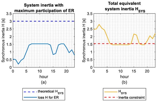
Figure 7.
Inertia behavior: (a) equivalent inertia of RES, (b) total equivalent inertia of power system.
The entered voltage constraint limits the voltage variation in each node within the range of ; the voltage profile obtained in the bars can be verified in Figure 8. In this figure, it can be seen that the minimum voltage level in the buses is 0.983 p.u. and the maximum is 1.016 p.u. This restriction ensures the participation of renewable resources since by reducing the power flow through the network by dispatching the demand locally in the bars, the system voltage drop is reduced.
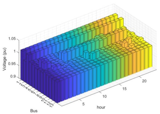
Figure 8.
Voltage at all buses without inertia constraint.
4.2. Case: Inclusion of the Inertia (H) Constraint
The inertia restriction set out in Equation (17) is included to ensure frequency stability. The problem is solved by taking a total resolution time of 2.828 s.
In Figure 9, it can be seen that the dispatch model with inertia restriction maintains priority in the participation of renewable resources in the system dispatch.
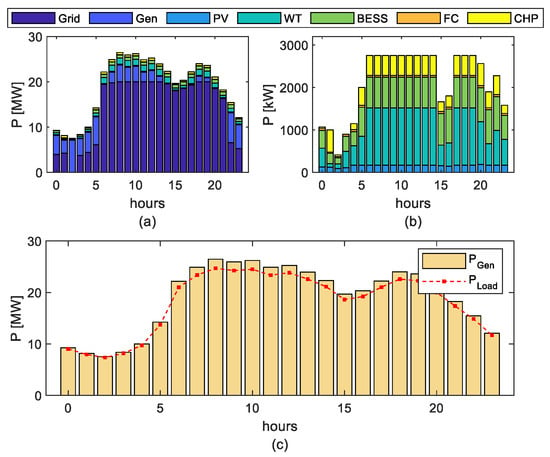
Figure 9.
Power dispatch: (a) reduction in RES participation due to inertia restriction; (b) view of renewable resources only (zoom); (c) electrical power balance with reduction in RES dispatch.
However, there is a reduction in the participation of renewable resources of 5.9%, equivalent to 3195.16 kWh. This guarantees a greater participation of the units with synchronous inertia.
To have a better perspective, the difference between the dispatch of renewable resources of the base case has been verified concerning the dispatch, including the inertia restriction, and these results are presented in Figure 10. In this figure, it can be seen that at 6:00 a.m. the wind unit increases its dispatch by 25.7 kW; however, the PV, BESS, CHP, and FC units reduced their dispatch by 196.9 kW. In the period from 7:00 a.m. to 1:00 p.m., there is a constant trend, and the reduction in the dispatch of units with renewable energy is repeated by 305.9 kW. The same reduction occurs at 6:00 p.m. and 7:00 p.m., while at 5:00 p.m., the reduction is 23.7 kW. During these hours of most significant demand, the dispatch of renewable resources has been minimized, thus guaranteeing a better inertia contribution than with the classic dispatch. The energy dispatch of the infinite bar compensates for this reduction in dependence on renewable resources.
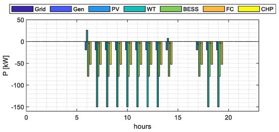
Figure 10.
Comparison of renewable resource dispatch without and with inertia constraint.
With the new dispatch data with inertia restriction, the available inertia of the system is evaluated. As shown in Figure 11, in the periods from 6:00 a.m. to 2:00 p.m. and from 5:00 p.m. to 7:00 p.m., the inertia of the system is recovered by 5.9%. Due to the increase in the participation of the infinite bar in the dispatch instead of the renewable resources, the minimum limit of inertia of the system is 1.62 s, which is greater than the minimum inertia limit of 1.54 s proposed as a restriction.
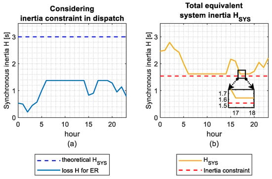
Figure 11.
Inertia behavior: (a) reduction in equivalent inertia through dispatch of renewable resources RE; (b) total equivalent inertia of power system with inertia constraint.
The voltage profile obtained in the bars when the inertia constraint is considered varies slightly; however, the voltage variation in each node remains within the range of . The voltage profile obtained in the bars before and after considering the inertia constraint can be verified in Figure 12.
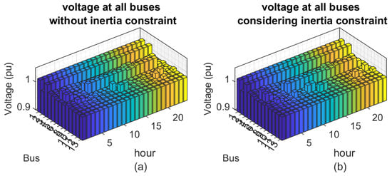
Figure 12.
Voltage profile (a) without and (b) with inertia constraint.
A total value of the transport losses over 24 h is obtained as 30.20 kW/h, equivalent to 0.0528%. This is a negligible value considering that the whole generation during the entire process will be 572 MW/h; this is for the case with a maximum participation of RESs. On the other hand, the losses obtained in the system with the reduction in RESs due to the inertia restriction cause the losses to increase to 36.5 kW/h, representing an increase in energy losses in the distribution network of 20.8% when the participation of the RES is reduced. This is because the circulation of current through the distribution network from the slack bar to the loads is increased to compensate for the power reduction due to the inertia restriction in the RES. Figure 13 illustrates the results obtained.
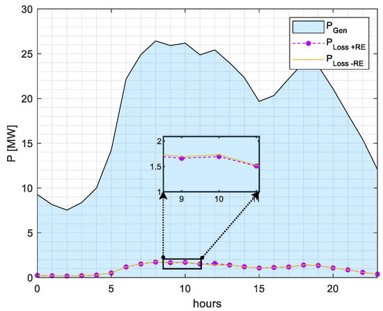
Figure 13.
Losses in the system.
Regarding the cost of the operation, the results are presented in Figure 14; as can be seen, there is a reduction in the cost of dispatch in the periods from 6:00 a.m. to 2:00 p.m. and from 5:00 p.m. to 7:00 p.m. This is because to recover the inertia of the system and keep it within the limit, synchronous generation is increased, which has lower operating costs for the proposed case study.
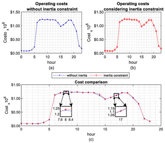
Figure 14.
Operating costs (a) without inertia constraint in dispatch, (b) with inertia constraint, and (c) a comparative analysis.
The objective function is $1,242,146.3 for the maximum demand at 8:00 a.m. and $77,295.0 for the minimum demand at 2:00 a.m. for the base case. For the case with inertia restriction, the objective function is $1,234,856.70 for the maximum demand at 8:00 a.m. There is a reduction of $7289.60 to recover 0.08 s of inertia in the dispatch for that time concerning the base case. From this, an estimated cost of $91.12 per millisecond of synchronous inertia is obtained. For the minimum demand, there is no variation concerning the base case. As shown in Figure 15, the highest costs occur when there is a greater participation of renewable resources because they have the highest operating costs. The total transaction for the base case is $19,187,483.0; for the case with inertia restriction, it is $19,254,491.56. Therefore, there is a recovery of $67,008.56 by reducing the participation of renewable resources by 5.9% to ensure the system’s stability.
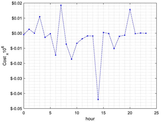
Figure 15.
Cost of inertia.
Through an exhaustive review of the literature, it has been possible to determine a minimum inertia value for this system, which amounts to 1.54 s. In the case of classic dispatch, it was observed that this value was exceeded during the periods from 6:00 to 14:00 and from 17:00 to 19:00. However, by introducing the inertia constraint in the execution of the classic dispatch case, effective control was achieved. The minimum inertia of the system was maintained within the required limits throughout the dispatch horizon, including the mentioned periods in which the limit was previously exceeded.
Furthermore, it is relevant to highlight that including this inertia restriction significantly reduced operating costs. The total shipping cost for the base case was $19,279,819.0, while by implementing the inertia constraint, the costs were reduced to $19,187,483.3. This saving is mainly due to the greater use of synchronous generation on the grid, which has a cheaper operating cost, as detailed in Figure 14.
5. Conclusions
This study poses the crucial task of maintaining the synchronous inertia of the electrical system within thresholds that safeguard the global stability of the system. This objective is achieved by implementing an optimal real-time dispatch approach for renewable resources, which incorporates a constraint that establishes a minimum level of inertia necessary for the system’s proper functioning. The results obtained in this study are revealing since they show that the voltage profiles are constantly maintained within a margin of . It is especially noteworthy that including the inertia constraint in the dispatch process allows for effective and sustained control of the minimum inertia of the system at all times of the dispatch horizon. This, in turn, translates into a significant reduction in operating costs. The total dispatch cost for the case incorporating this inertia constraint amounts to $19,187,483.3, compared to $19,279,819.0 for the base case. These results demonstrate that implementing this restriction leads to substantial savings of $67,008.56, representing a 5.9% decrease in the total operating costs, highlighting the effectiveness of this strategy in terms of economic efficiency in the operation of the electrical system.
Author Contributions
The research was carried out successfully with the contribution of three authors. The main idea of the research, review, the preparation of the manuscript, and the translation were by A.Á.T., L.O. and L.C. They contributed to the development, the implementation of the simulation and experimentation, the analysis of these data, and the preparation of the manuscript. All authors have read and agreed to the published version of the manuscript.
Funding
This research received no external funding.
Data Availability Statement
All result data is displayed in the document.
Conflicts of Interest
The authors declare no conflict of interest.
Nomenclature
| AND | Active distribution network |
| APSO | Adaptive particle swarm optimization |
| BESS | Battery energy storage system |
| CHP | Combined heat and power |
| CS | Cuckoo search |
| DER | Distributed energy resources |
| ED | Economic dispatch |
| ERCOT | Electric Reliability Council of Texas |
| FC | Fuel cell |
| MG | Microgrid |
| MILP | Mixed integer linear programming |
| NLP | Nonlinear programming |
| NORDIC | The Nordic Region |
| OPF | Optimal power flow |
| PSO | Particle swarm optimization |
| PV | Solar photovoltaics |
| RES | Renewable energy sources |
| ROCOF | Rate of change of frequency |
| UC | Unit commitment |
| UCED | Unit commitment and economic dispatch |
| UFLS | Under-frequency load shedding |
| WBS | Wind–battery hybrid power system |
| WT | Wind turbine |
| Subscripts | Definition |
| i | Synchronous generation units |
| j | Renewable Energy Sources |
| k | Sending bus |
| m | Receiving bus |
| t | Time intervals |
| Parameters | |
| Minimum inertia of the system (s) | |
| Active power demand at bus k (MW) | |
| Maximum/minimum limits of active power, synchronous generation unit i | |
| Reactive power demand at bus k (MW) | |
| Maximum/minimum limits of reactive power, synchronous generation unit i | |
| Vmax/min | Maximum/minimum voltage limits at all nodes |
| ai, bi, ci | Operating cost coefficients of unit i ($/MWh2, $MWh and $/h) |
| f0 | Nominal frequency of the system (p.u) |
| Active power connected to bus k at time t (MW) | |
| Reactive power connected to bus k at time t (MVAr) | |
| ykm | Admittance of branch connecting bus k to m |
| βj | Operating cost coefficient of RES j at time t ($/MWh) |
| Nb | Set of all buses |
| Ng | Set of buses with synchronous generators. |
| Nr | Set of buses with RESs |
| T | Number of time intervals t (24 h) |
| π | Limits of voltage angle of bus k (rad) |
| Variables | |
| CCG | Cost of synchronous generation ($) |
| CDER | Cost of generation with RES ($) |
| CT | Total operating costs ($) |
| Scheduled output active power for synchronous generation unit i at time t (MW) | |
| Scheduled output active power for RES generation unit j at time t (MW) | |
| Scheduled output reactive power for synchronous generation unit i at time t (MVAr) | |
| vk/m | Voltage magnitude at bus km at time t (V) |
| δk,t | Voltage angle of bus k at time t (rad) |
References
- Zografos, D. Power System Inertia Estimation and Frequency Response Assessment. Ph.D. Thesis, KTH, School of Electrical Engineering and Computer Science, Stockholm, Sweden, 2019. [Google Scholar]
- Hartmann, B.; Vokony, I.; Táczi, I. Effects of decreasing synchronous inertia on power system dynamics—Overview of recent experiences and marketisation of services. Int. Trans. Electr. Energy Syst. 2019, 29, e12128. [Google Scholar] [CrossRef]
- Agrawal, U.; O’Brien, J.; Somani, A.; Mosier, T.; Dagle, J. A Study of the Impact of Reduced Inertia in Power Systems. In Proceedings of the 53rd Hawaii International Conference on System Sciences, Grand Wailea, HI, USA, 7–10 January 2020; Volume 3, pp. 3010–3017. [Google Scholar]
- Denholm, P.; Mai, T.; Kenyon, R.W.; Kroposki, B.; O’Malley, M. Inertia and the Power Grid: A Guide Without the Spin; Technical Report 1659820; National Renewable Energy Lab: Golden, CO, USA, 2020. [Google Scholar]
- Fernández-Guillamón, A.; Gómez-Lázaro, E.; Muljadi, E.; Molina-García, Á. Power systems with high renewable energy sources: A review of inertia and frequency control strategies over time. Renew. Sustain. Energy Rev. 2019, 115, 109369. [Google Scholar] [CrossRef]
- Zhao, J.; Lyu, X.; Fu, Y.; Hu, X.; Li, F. Coordinated Microgrid Frequency Regulation Based on DFIG Variable Coefficient Using Virtual Inertia and Primary Frequency Control. IEEE Trans. Energy Convers. 2016, 31, 833–845. [Google Scholar] [CrossRef]
- Kerdphol, T.; Rahman, F.S.; Watanabe, M.; Mitani, T. Virtual Inertia Synthesis and Control; Part of the book series Power Systems; Springer: Berlin/Heidelberg, Germany, 2021. [Google Scholar]
- National Technical University of Athens. Renewables 2018—Global Status Report; REN21: Paris, France, 2018. [Google Scholar]
- Daly, P.; Flynn, D.; Cunniffe, N. Inertia considerations within unit commitment and economic dispatch for systems with high non-synchronous penetrations. In Proceedings of the 2015 IEEE Eindhoven PowerTech, Eindhoven, The Netherlands, 29 June–2 July 2015; Institute of Electrical and Electronics Engineers Inc.: Piscataway, NJ, USA, 2015. [Google Scholar]
- Davarinejad, E.; Reza Hesamzadeh, M.; Chavez, H. Incorporating Inertia Constraints into the Power Market; Technical Report 2017:392; Energiforsk: Stockholm, Sweden, 2017. [Google Scholar]
- Wang, T.; Meskin, M.; Zhao, Y.; Grinberg, I. Optimal Power Flow in Distribution Networks with High Penetration of Photovoltaic Units. In Proceedings of the IEEE Electrical Power and Energy Conference (EPEC), Saskatoon, SK, Canada, 22–25 October 2017. [Google Scholar]
- Ma, Y.; Zou, G.; Hou, M.; Dong, Q.; Yang, J. Optimal dispatching for active distribution network with wind-battery hybrid power system. In Proceedings of the 2017 IEEE Electrical Power and Energy Conference (EPEC), Saskatoon, SK, Canada, 22–25 October 2017; pp. 1–6. [Google Scholar]
- Xia, H.; Li, Q.; Xu, R.; Chen, T.; Wang, J.; Hassan, M.A.S.; Chen, M. Distributed Control Method for Economic Dispatch in Islanded Microgrids with Renewable Energy Sources. IEEE Access 2018, 6, 21802–21811. [Google Scholar] [CrossRef]
- Guggilam, S.S.; Zhao, C.; Dall’Anese, E.; Chen, Y.C.; Dhople, S.V. Optimizing Power-Frequency Droop Characteristics of Distributed Energy Resources. IEEE Trans. Power Syst. 2018, 33, 3076–3086. [Google Scholar] [CrossRef]
- Moghaddas-Tafreshi, S.M.; Mohseni, S.; Karami, M.E.; Kelly, S. Optimal energy management of a grid-connected multiple energy carrier micro-grid. Appl. Therm. Eng. 2019, 152, 796–806. [Google Scholar]
- Rebollal, D.; Chinchilla, M.; Santos-Martin, D.; Guerrero, J.M. Endogenous approach of a frequency-constrained unit commitment in islanded microgrid systems. Energies 2021, 14, 19. [Google Scholar]
- Lu, T.; Jiiang, D.; Jia, Y. Estimation of Generator Inertia Using Mean Value of Active Power Change After a Disturbance. In Proceedings of the 2019 IEEE Sustainable Power and Energy Conference (iSPEC), Beijing, China, 21–23 November 2019; IEEE: Piscataway, NJ, USA, 2019. [Google Scholar]
- Hellebust, H. Analysis of Frequency Stability: How Wind Power and HVDC Connections Affect the Future Power System. Master’s Thesis, Norwegian University of Science and Technology, Trondheim, Norway, 2018. [Google Scholar]
- Sølna, A.H. Strategies to Ensure Sufficient Inertia in the Norwegian Power System. Master’s Thesis, Norwegian University of Science and Technology, Trondheim, Norway, 2018. [Google Scholar]
- Seneviratne, C.; Ozansoy, C. Frequency response due to a large generator loss with the increasing penetration of wind/PV generation—A literature review. Renew. Sustain. Energy Rev. 2016, 57, 659–668. [Google Scholar] [CrossRef]
- Persson, M. Frequency Response by Wind Farms in Power Systems with High Wind Power Penetration. Ph.D. Thesis, Chalmers University of Technology, Gothenburg, Sweden, 2017; 178p. [Google Scholar]
- Fang, J.; Li, H.; Tang, Y.; Blaabjerg, F. On the Inertia of Future More-Electronics Power Systems. IEEE J. Emerg. Sel. Top. Power Electron. 2019, 7, 2130–2146. [Google Scholar] [CrossRef]
- Jorgenson, J.; Denholm, P. Modeling Primary Frequency Response for Grid Studies; Technical Report 1489895; National Renewable Energy Lab: Golden, CO, USA, 2019. [Google Scholar]
- Greve, T.; Teng, F.; Pollitt, M.G.; Strbac, G. A system operator’s utility function for the frequency response market. Appl. Energy 2018, 231, 562–569. [Google Scholar] [CrossRef]
- Chen, H.; Ngan, H.; Zhang, Y. Power System Optimization: Large-Scale Complex Systems Approaches; Wiley: Hoboken, NJ, USA, 2016; 359p. [Google Scholar]
- Wood, A.J.; Wollenberg, B.F.; Sheblé, B.G. Power Generation, Operation, and Control; Wiley: Hoboken, NJ, USA, 2014. [Google Scholar]
- Zhu, J. Optimization of Power System Operation, 2nd ed.; Mohamed, E., Hawary, E., Eds.; Wiley: Hoboken, NJ, USA, 2015. [Google Scholar]
- Gómez, A. Analisis y Operacion de Sistemas de Energia Eléctrica; Graw Hill: New York, NY, USA, 2002. [Google Scholar]
- Scarabaggio, P.; Carli, R.; Dotoli, M. Noncooperative Equilibrium-Seeking in Distributed Energy Systems under AC Power Flow Nonlinear Constraints. IEEE Trans. Control Netw. Syst. 2022, 9, 1731–1742. [Google Scholar] [CrossRef]
- Yao, M.; Molzahn, D.K.; Mathieu, J.L. An optimal power-flow approach to improve power system voltage stability using demand response. IEEE Trans. Control Netw. Syst. 2019, 6, 1015–1025. [Google Scholar] [CrossRef]
- Nayak, C.K.; Kasturi, K.; Nayak, M.R. Economical management of microgrid for optimal participation in electricity market. J. Energy Storage 2019, 21, 657–664. [Google Scholar] [CrossRef]
- Strunz, K. Benchmark Systems for Network Integration of Renewable and Distributed Energy Resources. CIGRE Task Force C6.04.02; ELECTRA. July 2014. Volume 575. Available online: https://e-cigre.org/publication/ELT_273_8-benchmark-systems-for-network-integration-of-renewable-and-distributed-energy-resources (accessed on 25 June 2022).
- Solanki, B.V.; Bhattacharya, K.; Canizares, C.A. A Sustainable Energy Management System for Isolated Microgrids. IEEE Trans. Sustain. Energy 2017, 8, 1507–1517. [Google Scholar] [CrossRef]
- Henze, V. Scale-Up of Solar and Wind Puts Existing Coal, Gas at Risk//BloombergNEF. 2020. Available online: https://about.bnef.com/blog/scale-up-of-solar-and-wind-puts-existing-coal-gas-at-risk/#_ftnref1 (accessed on 25 June 2022).
Disclaimer/Publisher’s Note: The statements, opinions and data contained in all publications are solely those of the individual author(s) and contributor(s) and not of MDPI and/or the editor(s). MDPI and/or the editor(s) disclaim responsibility for any injury to people or property resulting from any ideas, methods, instructions or products referred to in the content. |
© 2023 by the authors. Licensee MDPI, Basel, Switzerland. This article is an open access article distributed under the terms and conditions of the Creative Commons Attribution (CC BY) license (https://creativecommons.org/licenses/by/4.0/).