Abstract
The modernization, efficiency, and decarbonization of the energy supply systems are among the new challenges to be faced in the coming decades to achieve the targets and objectives dictated by European strategic policies. Despite the countless benefits related to renewable energy sources (RES) integration, this brings key challenges to the power system, such as the risk of imbalance between energy generation and demand, sudden changes in flows in transmission lines with a need for expensive and time-consuming upgrades, and the withdrawal of conventional generation systems with consequent demands for new solutions and innovation to support grid services. A potential solution to limit the huge intermittence and fluctuation in power generation from RES is Concentrated Solar Power (CSP) technology integrated with thermal energy storage. The aim of this paper is to discuss the potential benefits related to the use of CSP technology by presenting innovative industrial solutions developed in the Italian SOLARGRID Project, namely the hybridization of CSP–PV systems and the solar thermo-electric system developed by MAGALDI, the parabolic trough collector of Eni, and the new linear Fresnel reflector configuration of IDEA S.r.l. These plant and component solutions are developed for improving the technical performance of CSP technology and reducing the levelized cost of electricity, thereby fostering an effective and massive deployment and encouraging the creation of new business models.
1. Introduction
The energy sector plays a crucial role in the growth of national economies as a production factor oriented to integrate innovation solutions to reduce energy generation costs and improve the quality of the carriers used for delivering energy to end-users and as a growth factor to support and facilitate the pursuit of the decarbonization targets defined by the national and European strategic agendas [1]. Renewable Energy Source (RES), energy efficiency, and flexibility in final energy use are among the priority measures to foster sustainable development of an energy system as a whole [2,3]. The development of RES integrated with high-efficiency systems is essential since they are usually characterized by low environmental impacts and contribute to increasing the penetration of distributed generation and cogeneration systems within traditional networks. Furthermore, renewable technologies can also be seen as the main driver for accelerating the development of smart grids and Energy Communities (ECs) [4,5,6,7].
The renewable energy supply chain, although characterized by different levels of technological maturity and economic competitiveness, generally requires industrial research, innovation, and competitive development efforts: (i) to reduce CAPital EXpenditure (CAPEX) and OPerating Expenditure (OPEX) costs related to the implementation of the energy technologies involved; (ii) to optimize performance and increase the system’s efficiency and reliability; (iii) to develop hybridization and RES integration solutions for the combined generation of electricity and heat with the aid of distributed energy storage systems; (iv) to develop and implement advanced control logic and management systems [8].
Among the various renewable technologies for electricity production, systems based on solar energy, including photovoltaic (PV) systems and concentrating solar power (CSP) systems, are the most widely used [9]. Currently, PV systems are dominating the market for solar energy production, accounting for approximately 98% of new annual installations of solar-based systems on a global scale [10]. In 2021, PV systems with a total capacity of 848.4 GW and CSP systems for 6.4 GW were installed. Overall, over the last decade, the solar technology sector has seen growth of 719%, with installed capacity increasing from 104.3 GW in 2012 to 854.8 GW in 2021 [11,12]. Furthermore, over the same period, the installed capacity of CSP increased by 149% globally [11]. Unlike PV technology, which directly converts solar energy into electricity, CSP systems concentrate direct normal irradiance (DNI) onto a receiver through mirrors or lenses [13], allowing the conversion of concentrated solar radiation into thermal energy at high temperatures, which is then transformed into mechanical energy by means of a thermodynamic cycle. Mechanical energy is thus converted into electricity [14,15].
Despite the countless benefits related to RES integration, this brings new challenges to energy systems, such as the risk of imbalance between energy generation and demand, sudden changes in flows in transmission lines with a need for expensive and time-consuming upgrades, and, moreover, withdrawal of conventional generation systems with consequent demands for new solutions and innovation to support grid service provision [16]. A potential solution that limits the huge intermittence and fluctuation in power generation from RES and makes it usable, even when the primary resource (e.g., wind and sun) is not available, is the CSP technology integrated with long-term thermal energy storage (TES) [17]. In fact, predictability, the reliability of production, and dispatchability are achievable thanks to the integration with thermal storage, high efficiency in terms of costs, low use of critical raw materials, and the potential employment of recyclable materials with low environmental impact represent the main advantages of CSP technology.
The CSP systems can be broadly classified into two main categories: line-focusing and point-focusing [18]. Line-focusing systems, such as linear parabolic systems and linear Fresnel reflectors, use long, curved mirrors to concentrate solar radiation onto a receiver tube positioned along the focal line. The receiver tube contains a heat transfer fluid (HTF) that is heated up by concentrated solar radiation, and the resulting thermal energy is then used to generate steam and supply a turbine to produce electricity. On the other hand, point-focusing systems, including dish-Stirling systems and solar towers, concentrate solar radiation on a single point or a small area. Dish-Stirling systems use a paraboloid-shaped collector to reflect and concentrate the direct solar radiation incident on the focal point where the power conversion unit (PCU) is installed. This is achieved through a biaxial solar tracking system, which can maintain continuous alignment between the focal axis and the direction of the sun’s rays, following the apparent position of the sun in the sky during the day. The PCU includes the receiver, the engine for the conversion of thermal energy into mechanical energy (e.g., through a Stirling engine or a microturbine), and the electric generator for converting mechanical energy into electrical energy. The receiver permits the most elevated temperature level of the thermodynamic cycle to be kept up by managing heat to the hot chamber of the Stirling engine, whereas a cooling system removes the heat from the cold chamber, wasting it through the environment, to preserve the level of the lower temperature of the cycle [18]. Solar tower systems are characterized by a series of mirrors or heliostats that reflect incident solar irradiance onto a central receiver located at the top of a tower. The receiver absorbs concentrated radiation and transfers the resulting thermal energy to an HTF. The latter is then used to produce steam and generate electricity.
Several factors may influence the performance of CSP systems, such as the outside air temperature, the level of DNI, and the fouling factor of the reflective surface [19]. Among these, the DNI level is the factor having the greatest influence on the manufacturability of a CSP system and essentially depends on the geographical location of the installed plant. The regions of the Sun Belt, North Africa (MENA), South Africa, the Middle East, Australia, Chile, and south-western Europe offer the most favorable conditions for the installation of CSP systems, thanks to the abundance of direct solar radiation. All operational, non-operational, and CSP projects under construction are located in these areas, as indicated by Solar Power and Chemical Energy Systems (SolarPACES) [20].
The Italian SOLARGRID Project (Thermodynamic and Photovoltaic Solar Systems with Storage for co-generation and network flexibility) [21] is collocated in this context. The main goal of the project is indeed to achieve a technical–economical optimization and improved competitiveness of CSP and thermodynamic solar technology based on the use of parabolic trough and linear Fresnel systems by means of technological improvements on solar tracking systems, as well as the identification of improved solutions for CSP technology based on the use of centralized “beam-down” tower systems with fluidized-beds TES, in order to improve the energy performance, with a key focus on system optics. The SOLARGRID project also aims at maximizing research implications in concrete industrialization and market activities to translate the demand for innovative technologies and components into development opportunities and competitive growth for the national industry, thereby helping support a cost-effective energy transition and encouraging the creation of new business models. Developed in the framework of the SOLARGRID project, the main contribution of this work is to comprehensively discuss the key benefits and challenges related to the use of CSP technology by presenting innovative industrial solutions and methodologies aiming at the improvement of the technical performance and the reduction of the levelized cost of electricity (LCOE) of CSP. A detailed critical analysis of the CSP technology is first presented, focusing attention on the main technical and technological solutions, their implementation and development status, and key issues and challenges to address for massive deployment. Then, the advantages deriving from the development of innovative industrial solutions for CSP components and systems are presented by exploring the enhancement of flexibility and the increased reliability achieved by coupling CSP and PV technologies, the proposed new concept related to the STEM technologies of Magaldi Power S.p.A., the advanced parabolic trough collector realized by Eni S.p.A., and the new linear Fresnel reflector (LFR) concept developed by IDEA S.r.l. All these innovative solutions aim to reduce the LCOE and improve the technical performance of CSP, making them competitive with other renewable technologies for electrical and thermal energy production.
The paper is structured as follows. Section 2 presents a detailed analysis of the CSP technologies with a look at future perspectives. In detail, this section discusses the main characteristics, the development status, the primary barriers to the CSP system implementation, and the main recommendations to overcome them. Section 3 discusses the main results and innovation aspects achieved in the SOLARGRID project, namely the hybridization of CSP–PV systems and the solar thermo-electric system developed by MAGALDI, the parabolic trough collector of Eni and the new LFR configuration of IDEA S.r.l., whereas Section 4 summarizes the conclusions and lessons learned from the study.
2. Analysis of Concentrated Solar Power Technology and Future Perspectives
This section aims to present a detailed analysis of CSP technology, with a key focus on the main technical solutions, their implementation and development status, and key issues and challenges to address for a massive deployment.
2.1. Line-Focusing CSP Systems
2.1.1. Linear Parabolic Systems
Linear parabolic collectors consist of a concentrator that has a linear parabolic profile, with reflective surfaces that follow the sun, through a rotation mechanism on a single axis, to focus the solar radiation on a receiver tube positioned along the focus of the parabola. The solar energy absorbed by the receiver tube is transferred to a working fluid that is an HTF. The main characteristics of linear parabolic systems are shown in Figure 1.
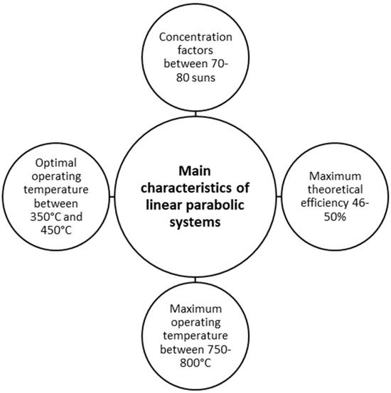
Figure 1.
Main characteristics of linear parabolic systems with temperature and efficiency values calculated in ideal conditions (100% conc. Efficiency, black body) [22].
The HTF most used in these systems is synthetic oil, which has a maximum operating temperature of approximately 400 °C, which limits the conversion efficiency of the power generation cycle. For this reason, researchers and industry have developed advanced HTFs capable of reaching higher temperatures (up to 600 °C). One example is the use of molten salts. This “second generation” of the HTF is expected to lead to significant improvements in average conversion efficiency and further reductions of energy production cost. Although some demonstration plants have already been built with these “second generation” HTFs, more operational experience is still needed [23].
It has to be mentioned that Parabolic Trough (PT) systems represent the most widely used CSP technology at present, as shown in Figure 2.
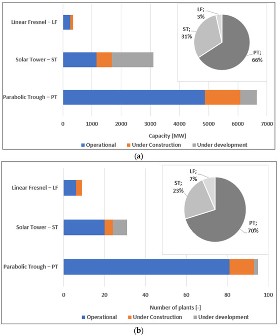
Figure 2.
(a) Global plant capacity (MW) broken down by technology (Fresnel, linear parabolic, and solar tower)—operational, under construction, and under development. (b) Global number of CSP power plants by technology—operational, under construction, and under development [20].
The existing CSP plants represent 78% (approximately 4900 MW) of the total installed and operational capacity. PT technology can be considered “mature” as several manufacturers are available for building entire plants or subsystems. There is good experience (at least 20 years) in the procurement, design, construction, and operational management of these systems, and good functional reliability has been achieved [20,23,24].
Most of the PT solar plants currently in operation are designed to produce electricity. These plants have sizes from 15 to 100 MWe, an average overall efficiency of 14–16% (in terms of the ratio between net electrical energy produced and input solar energy), and a maximum operating temperature of 390 °C due to the stability limits of the HTF (synthetic oil). Most of these systems are sized to store high quantities of thermal energy using TES systems based on double tanks of molten salts.
The architecture of the PT solar field is similar for all the installations. Usually, the solar field has a square plan, and in its center, there is a TES and power block. The solar field is composed of different strings of solar collectors. Every string is linked with a power block and TES through a pipe loop connected with all solar strings. Every string is composed of two or more lines of solar collectors with a length ranging between 300 and 400 m. Each line is made up of 3–4 solar collectors. Each solar collector consists of a series of aligned manufactured modules, generally 4 m long, supported by pylons. The central pylon is equipped with a tracking system to move the PT and follow the sun’s position with respect to the horizon line. The collector movement system can be hydraulic or electromechanical and is controlled through optical pointing devices or software tools aimed at calculating the position of the sun at any moment. In large systems, each collector is typically 100 m long, with an opening to the order of 6 m. Recently, collectors up to 190 m long, with an opening greater than 8 m, have been introduced in power generation plants. In PT systems aiming at producing process heat, the dimensions are generally smaller (lengths of 50 m and openings of 2–3 m).
PT collectors (PTC) had a strong development in the 1980–1990 years, with the construction of nine plants for a total power of 354 MW in the California desert. The construction of new thermodynamic solar plants based on PT technology came to a halt until 2000 when a new development program on an industrial scale began in Spain, which led to the construction of 45 PTC CSP plants for a total installed power capacity of about 1.8 GW (2.3 GW total CSP).
PT systems are suitable for a hybrid operation called integrated solar combined cycle (ISCC), where the steam generated by the solar source is fed into a thermal power plant, which also uses fossil fuels (usually natural gas) to generate steam. Examples of operational CSP and ISCC plants are the 25 MW-Hassi R’mel in Algeria, the 20 MW-Al Kuraymat in Egypt, and the 20 MW-Ain Beni Mathar in Morocco (the other three ISCC plants are currently under construction, namely two in Saudi Arabia and one in Mexico) [23]. The main benefits of PT systems are essentially related to the simple design of optical systems, that also guarantee high concentration ratios, and to the possibility of assimilating commercial CSP systems to parabolic collectors that use oil as the HTF to other types of industrial plants, thus taking advantage of existing industrial supply chains. Currently, the minimal annual level of DNI required for a CSP plant to become profitable is 1800–2000 kWh/m2 per year, while for the process heat generation, a significantly lower threshold DNI is requested (1200–1300 kWh/m2), which explains the development of some applications in certain northern countries, such as Denmark (Aalborg 2020) [25] and Belgium (Oostende, ADPO, Port of Antwerp).
With specific reference to Italy, the suitable geographical areas for large-scale CSP applications for power generation—considering the current installation costs and the optimal conditions for their use—are limited only to a limited part of the national territory as Sicily, southern Puglia, and part of Sardinia [26]. Disused industrial areas or exhausted landfills represent the best conditions for installation, as these systems represent a useful way to redevelop the environment. In this context, the capacity of solar thermal power plants to bulk store the collected solar energy at low cost is an asset for their future deployment. In 2011, the Italian potential of CSP technology was estimated at 600 MW [27], but to date, only 5 MW have been installed. More factors have contributed to not reaching the goal set in 2011. The Italian stakeholders have individuated two key factors as the reason why the CSP did not spread to Italy as expected. The first problem was the lag between the release of the ministerial decrees with incentives for solar thermodynamic and the actual complex authorization process. A problem that started with the first decrees of 2008 and continued in 2012 with the lack of authorizations, mostly at the regional level. The 2016 decree, which allowed incentives for large CSP plants through auctions, was not successful, as the auctions had to close in 3–4 months and no investor, even though this time with the authorizations in hand, had enough time to investigate on the return of investment in power plants with the CSP technology. Furthermore, the decree provided for the payment of a high deposit via bank guarantee, to be paid only to participate in the auction. The second factor that has blocked the sector is linked to the distrust of local communities in accepting the technology. Policies related to climate change and objectives related to the implementation of the European Green Deal may represent a new opportunity for PTC system technology in Italy and Europe.
The CSP plants, coupled with thermal storage, can play a key role by supporting a smart integration of RES. On the other hand, the large-scale CSP plants can help to cope with grid and flexibility issues on a broader level. In detail, the CSP systems, coupled with long-term TES, represent a better solution for a power grid characterized by variable electrical loads than a power grid characterized by constant electrical demand. This is because CSP plants can be designed to feed an optimized average load profile derived from the interpolation of the valleys and peaks of the load profile. This allows for reducing the solar multiple (and therefore the size of the mirror field) and the capacity of the TES, resulting in a lower cost compared to a scenario with constant demand. This characteristic can enhance coupling PTC–CSP plants with other RES like PV and/or Wind.
The integrated CSP–PTC/PV systems coupled with molten salt storage systems allow solar energy to be injected into the grid in a flexible and programmable way to follow the demand curve, thus minimizing the effects of the fluctuations of the renewable source on the management of the power grid and maximizing coverage of the load from solar source [28]. This characteristic allows integrated CSP–PTC/PV systems to be considered a technical solution particularly suitable for Italy. Several analyses have shown that hybrid CSP/PV plants with a size of 50 MW built in peninsular Italy would be able to satisfy almost 70% of the hourly electricity load [29]. With the same load profile considered, the integration between PV and CSP allows a greater share of the demand to be satisfied (compared to a pure CSP system) by reducing the cost of the energy produced (i.e., LCOE) from 10% to 30%. This is possible because the addition of a relatively simple and low-cost specific component, such as PVs, reduces the size of the more expensive components of the CSP section, such as the solar field and the power block. Additionally, the possibility of converting the excess PV production into heat through the electrical resistors of the TES, though thermodynamically inefficient, is successful from an economic point of view in increasing the dispatchability of PVs. In fact, the latter allows for exploiting the TES already present, which is also less expensive, instead of the battery characterized by high specific cost. Moreover, in the hybridization between CSP and wind and between CSP and PVs, wind is of particular interest since the trends of wind speed and solar radiation are not synchronous but, on the contrary, tend to be complementary [30].
The production of carbon-free heat for industrial, civil, and thermochemical applications is increasingly being considered by the scientific community as the very field of application of CSP technology for countries such as Italy, where the DNI does not reach high levels for long seasonal periods. Also, in this application, the coupling of CSP with thermal storage is fundamental. There are several hundred large solar thermal systems serving industries around the world. In these applications, PTC systems are mainly used for preheating feed water in steam boilers [31]. Moreover, in small-scale PTC systems, they can play an important role by feeding the users for thermal purposes in the building sector, as well as by producing industrial process heat for district heating, often enhanced with TES.
In this sector, among the new applications, the mini-CSP and the PTC–CST systems devoted to the co-production of electrical and thermal energy-serving ECs are of high interest. The mini-CSP refers to the use of thermodynamic solar technologies in small thermal or cogeneration applications (1 MW or slightly more), with smaller collectors, lower temperature of the HTF (no more than 350 °C), and the possibility of installation on the buildings’ roofs and industrial plants. These systems can find convenient applications in the industrial field to produce or process heat or in the tertiary sector for air conditioning purposes [32]. The PTC systems can be conveniently used to feed users that need low-temperature heat (<80 °C) and electricity. In this case, the PTC systems are coupled to Organic Rankine Cycle (ORC) or steam turbines, where the heat is the by-product of the thermodynamic process used in the power block. The use of PTC systems to directly feed users for thermal purposes is convenient only when the required temperature is higher than 120 °C [22].
In Italy, the food industries, agricultural product processing, and the chemical and petrochemical sectors, in which the use of heat at temperatures between 100 and 400 °C is expected, seem to be the most promising applications for CST systems based on linear PT systems. In these sectors, the technological challenge lies in the development of modular, expandable, and integrable concentrated solar technologies and in the identification of proper management and operation strategies to ensure stable operation of the process and reduced operating and maintenance costs [31].
The analysis of the cost of heat production from CST plants located in central and peninsular Italy for different thermal levels [33] shows that the cost of heat, in terms of Levelized Cost Of Heat (LCOH), currently stands on average between 5 and 7 c€/kWhth (considering an average solar field cost of 200 €/m2). The DNI characteristic of the installation sites significantly affects the final cost of the heat produced, with percentage variations in the LCOH ranging between 10 and 50%. The cost item with the greatest impact on the LCOH is the supply of the solar field (25–35%), followed by thermal storage, which represents 15% of the LCOH [33]. The integration of storage systems with CST plants determines an increase in CAPEX between 50 and 200%, depending on the hours of storage, and an increase in LCOH of approximately 5–20% [33]. These higher costs are compensated by the possibility of better integration of the CST systems with industrial processes. In this sense, the presence of the storage allows for increasing both the production hours and the stability of the thermal levels of the heat produced.
In Italy, a potential and promising application sector of PTC systems that has not been developed yet is the cooling sector of large buildings. All solar cooling systems are built using single-effect absorption machines. The use of double-effect absorption machines, and therefore of medium-temperature solar collectors, has the notable advantage of requiring a smaller collecting surface (about 40% compared to the single-effect machine and flat-plate solar collector solution) [22]. The development of medium-temperature solar collectors, which are also small, modular, and integrated with the roofing surface of buildings, could foster the creation of solar cooling systems by positioning the PTC collectors on otherwise unused spaces.
A local industry capable of producing the components for PT plants and, in general, a strong supply chain makes a country more attractive for the installation of CSP plants. The need to reduce CO2 emissions in highly urbanized areas, where installation sites are usually not available for the construction of large-scale CSP, is pushing research in the direction of developing medium-, small- or even micro-PTC solutions. They aim to optimize distributed generation, making an important contribution to Solar Heat for Industrial Processes (SHIP) solutions (heat at medium temperature for industrial processes) as well as positive energy districts in residential applications or heat and cooling solutions. Moreover, the growing interest in renewable energy communities could represent a new stimulus for the development of solutions based on linear concentration solar technologies for the harnessing of thermal energy in a heat and power cascade in urban areas.
The analysis elaborated on the potential barriers to the development of CST technology in Europe [33,34], highlighting that a mix of complementary policy measures is required to either activate drivers or mitigate barriers to CSP deployment in the future. The adoption of long-term targets, ensuring predictable changes in the remuneration for new plants, and avoiding retroactive changes for existing plants are considered by key stakeholders as essential elements for the CSP deployment [34,35]. The improvement of the performance and the cost reduction are important key drivers for their deployment. Some of the key Research and Development (R&D) actions identified to foster the enhancement of the diffusion of the PTC technology are listed in Table 1 [36]:

Table 1.
Key R&D actions identified to foster the spread of the PTC technology.
On the other hand, policies to encourage public–private partnerships, the cooperation between the industrial sector and the Research, Development, and Deployment (RD&D) sector on deployment projects, and support for collaboration at national and international levels are considered by key stakeholders as essential to remove or mitigate specific barriers (“proven technology,” “cost reductions,” and “technology risk”) and activate related drivers [34]. All these measures would also support “local manufacturing capabilities.”
2.1.2. Linear Fresnel reflectors
A typical linear Fresnel collector essentially includes two subsystems represented by the primary optical system and the secondary receiver. The primary optic system includes (i) the primary mirrors realizable in glass, metal, and plastic film; (ii) the mirror support, fabricable in metal, composite material, and structural sandwich; (iii) the mechatronic tracking system. The latter can include either linear actuators or specially designed geared motor systems, together with an astronomical type of control system based on solar sensors or a combination of astronomical tracking and pointing systems. The secondary receiver includes the secondary mirror, usually made of metal reflective sheets and the tubular absorber.
LFR systems, in their decades-long evolution, have explored numerous combinations of the above solutions. Numerous design concepts have been analyzed and proposed, and some of them have progressed to engineering design and prototyping. The first significant linear Fresnel collector was patented and prototyped by Giovanni Francia in Italy in 1964. This pioneering installation was not followed by significant industrial developments until the 2000s, characterized by a general revival of interest in CSP technologies. The first decade of the century saw the testing of the Solarmundo prototype in Belgium, the demonstration of the FRES DEMO project at the Plataforma Solar de Almeria (PSA) in Spain, the FERA collector prototype (CSP-F Solar) installed in Italy, and the German Mirroxx LFR system [37].
In the following decade, some LFR collectors were perfected for high-temperature applications. In particular, Novatec Solar (now Frenell) and Areva Solar represented the leaders in this type of application. The Novatec/Frenell system uses vacuum receiver tubes with a secondary reflector to reach temperatures up to 550 °C, while Areva Solar (formerly Ausra) installed a receiver assembly that includes multiple unevacuated steel receiver tubes [38]. SkyFuel has also made efforts to develop high-temperature LFR collectors using its ReflecTech reflective film technology in DOE-funded activities [39]. These players are joined by France’s SunCNIM with a collector usable for CSP and SHIP applications tested in a pilot plant [40].
Compared to parabolic systems, linear Fresnel collectors suffer from lower optical efficiency. However, linear Fresnel technology offers the ability to increase the concentration ratio, and therefore the receiver temperature, by increasing the aperture area of the reflector without substantially changing the design requirements of the system. For this reason, the LFR poses no difficulty, either structurally or mechanically, in attempting to maximize the geometric concentration ratio of the collector (i.e., the ratio of the mirror aperture to the receiver aperture) to achieve higher output temperatures. Finally, the drive system can be shared between mirrors of the same module, or it is possible to exploit coupling between adjacent modules to reduce the number of mechatronic components. However, there are still several technical/economic barriers to the deployment of this technology that require further investment in research and development, as indicated in Figure 3.
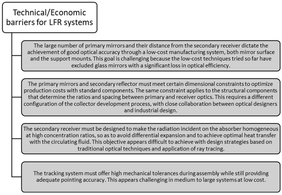
Figure 3.
Technical/Economic barriers identified for LFR systems.
2.2. Point-Focusing CSP Systems
2.2.1. Dish-Stirling Systems
Compared to other CSP technologies, dish-Stirling systems as point-focusing CSP have some advantages that make them an attractive choice for solar power generation. One of them is the high geometric concentration factor. The paraboloid shape of the reflector allows the concentration of incident solar radiation on a small focal point, with the consequent increase in both the energy density concentrated there and the upper limit of the operating temperature range. This explains how, in terms of energy efficiency, dish-Stirling solar concentrators hold the record for the efficiency of converting solar energy into electricity under nominal conditions [19]. Another advantage of dish-Stirling systems is the modular design. In fact, these systems can be built in a modular way, guaranteeing a high degree of flexibility and adaptability to energy generation on various scales [41]. Furthermore, dish-Stirling systems have a low level of land occupation compared to other solar technologies thanks to their high concentration efficiency [42]. Finally, dish-Stirling systems can be used for a wide range of applications, such as cogeneration integrated with heating, ventilation, and air conditioning technologies in residential buildings, combined with thermal energy storage, or hybridized with other RES. They are also suitable for electricity generation in remote rural areas and for the production of desalinated water [43].
Despite these advantages, dish-Stirling systems are the least widespread and least mature technologically among CSP technologies [17], as found through the analysis of data collected by SolarPACES. The limited adoption of dish-Stirling systems on a global scale can essentially be attributed, on the one hand, to the high initial cost associated with the complex design of the technology and components of the Stirling engine and, on the other hand, to the difficulty of integrating such systems with TES [44]. These factors make dish-Stirling systems less economically sustainable, preventing their widespread market diffusion. Certainly, the combined action of technological development associated with the adoption by national governments of a dedicated incentive scheme could trigger an economy of scale, such as making CSP systems competitive with other, currently more mature technologies by pushing for their diffusion.
Technological development could involve the recovery of low-temperature thermal energy on the cold side of the Stirling engine, which could be used to satisfy the winter heating needs of buildings (space heating) [45]. For this purpose, when the dish-Stirling system operates in a cogeneration setting, it is necessary to resolve the problem of temporal misalignment that exists between the annual period of maximum thermal energy production (summer) and the period in which greater thermal energy is required of the served user (winter). The solution consists of integrating the dish-Stirling system with a seasonal thermal energy storage system, Seasonal Thermal Energy Storage (STES) [46]. In this context, geothermal systems can be considered a promising source of residential heating thanks to their high thermal storage efficiency [47], for example, by installing a solar-assisted geothermal heat pump as described in [48,49]. There are different types of STES systems, as shown in Figure 4.
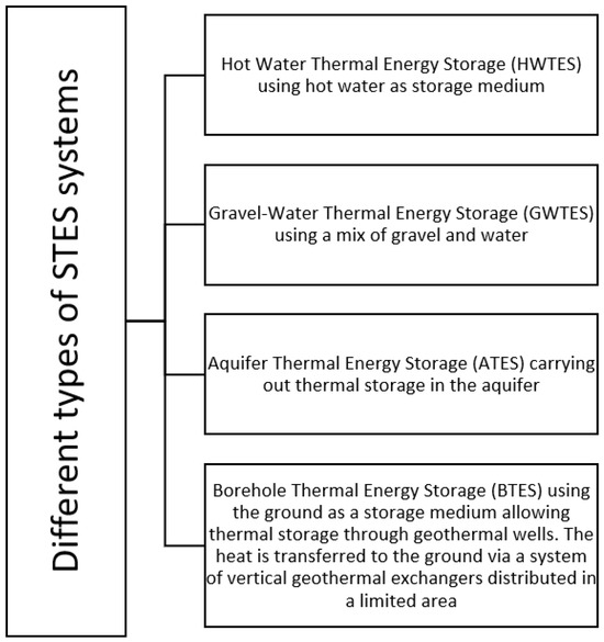
Figure 4.
Different types of STES systems with brief explanation [50].
The HTF, usually a solution of water and glycol, flows along the vertical exchanger, loading and unloading the soil and creating a radial temperature gradient which allows for reducing heat losses towards the outside or, better, towards the portion of thermally undisturbed soil surrounding the storage volume. The BTES system can also be thermally isolated on the upper boundary surface to limit the influence of external climatic conditions and minimize heat losses to the external environment [51]. Among the aforementioned sensible TES, BTES systems are the most suitable to be coupled with the cogenerative dish-Stirling type CSP technology due to the low temperature at which it is possible to recover the heat, the relative ease of installation, the moderate investment necessary to create the geothermal field [52] and the medium-high value of the thermal storage efficiency. The losses of thermal energy to the external environment are, in fact, limited due to the low enthalpy that characterizes the storage process and, therefore, the low temperature of the HTF used. BTES are already widely used worldwide [53].
2.2.2. Solar Tower Systems
Among the various technologies to produce clean energy through CSP, Solar Power Tower (SPT) plants are considered a promising technology and, in 2020, account for 15% of operational plants [54]. The technology is characterized by a heliostat field and a central receiver on the top of the tower, where the HTF is heated. High temperatures can be reached in the solar receiver, ensuring high cycle efficiency. An SPT uses a large number of heliostats, having a dual-axis control system (one for the vertical axis and the other for the horizontal axis), whose total collecting area can reach extensive dimensions, even hundreds of thousands of m2. As far as the heliostat field and its symmetry are concerned, there are two types of layouts: polar or 360° (surrounding) fields. Heliostats are spaced appropriately to limit shading phenomena. The distance between each heliostat increases as it moves away from the tower. The capturing surface of the individual heliostat is between 40 and 70 m2. The heliostats reflect the solar radiation on the focal point, which is fixed in time and space, in the solar receiver located at the top of the tower. The height of the tower depends on the solar field: the greater the number of heliostats, the higher the position of the focal point, up to more than a hundred meters. The solar radiation receiver can be of different types characterized by a configuration with external solar radiation collection or with cavities. The concentrated solar energy incident on the receiver is converted to thermal energy, which is carried by the HTF passing through the receiver. The thermal energy of the HTF is transferred to the working fluid of the power cycle, thereby generating electricity.
The advantage of SPTs is represented by the possibility of obtaining a high concentration ratio, referring to the ratio between the flux concentrated on the receiver and the ambient flux coming from the sun, ranging from 200 to 1000. Consequently, temperatures up to 1000 °C could be potentially reached with suitable HTFs. The high temperature leads to an increase in the power cycle efficiency. As a result, high overall solar-to-electric conversion efficiency can be achieved [55]. It can be highlighted that thermal efficiency (solar to mechanical) is estimated between 30% and 40% for this technology. This kind of system presents overall plant peak efficiency (solar to electric) values in the interval of 23–35%, while its annual solar to electric efficiency varies from 20% to 35% [56]. The fact that the latest SPTs give better LCOE [57,58] stands out, as they have a bigger potential for cost decrease and better performance when employing TES. The space for improvement of this concept is higher, and there are more plants currently under construction and development than the rest of the CSP technologies, thanks to their technical advantages [54,56].
The main HTFs used are water, molten salts, and, more recently, air and granular particles. Commercial-scale installations are generally equipped with absorber tubes or volumetric absorbers, which may be inside the cavity or arranged externally. Typically, the materials used for the construction of the receiver are ceramic materials or metals that are stable at high temperatures. SPTs are often coupled with TES systems, typically realized through two tanks, one for the hot fluid and one for the cold fluid. To date, there are countless studies presenting the potential of other types of HTFs, such as gas and/or solid particles [59] and advanced molten salts, to evaluate the possibility of improving the performances of SPT systems based on conventional molten salts.
In this context, the Generation 3 CSP Systems (Gen3 CSP), a funding program by the USA Department of Energy (DOE), builds on prior research for high-temperature concentrating SPT technologies [60]. The project is led by Sandia National Laboratories. Gen3 CSP focused on developing integrated assembly designs with TES to reach high operating temperatures using solid particles.
The first SPT plants in operation saw Spain lead the way: the PS10 plant, the first to supply electricity to the grid, started up in 2007, and later in 2009, the PS20 was also operational. In 2011, the GEMASOLAR plant with a 20 MW turbine and 15 h energy storage was put into operation in Spain. Plants start-up in the USA began with the Sierra SunTower plant in 2009, the Ivanpah in 2014, and the Crescent Dunes in 2015. The Ivanpah plant, with its 377 MW turbine, is one of the largest power plants in the world [17,61]. Crescent Dunes plant used an external cylindrical receiver with molten salts as HTF and incorporated a 10 h storage. Also, in China, several SPT plants are taking shape and going into operation; for instance, in 2013, the 10 MW Supcon and in 2018, the 50 MW Supcon. Other plants are under construction and/or development, such as the Golmud 100 MW. The Sundrop project realized in 2016 in Australia enabled seawater desalination and electricity generation through SPTs. Moreover, SPT plants are being developed in the MENA region. The Noor-III commercial plant located in Morocco started operation in 2018 with 150 MW and 7 h of storage capacity, while the 100 MW DEWA SPT plant has been in operation in Dubai since 2023. Another region of the world with high insolation is Chile, which has vast desert areas for the construction of SPT plants, and to date, Cerro Dominador is in operation [62].
2.3. Key Takeaways of the CSP Technologies Analyzed
This section aims to briefly summarize the key takeaways of the CSP technologies analyzed in detail in the previous subsection through Table 2, whereas the four technologies are illustrated in Figure 5.
Table 2.
Key takeaways of all CSP technologies analyzed in the paper.
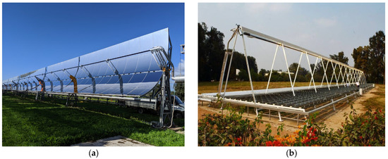
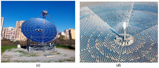
Figure 5.
CSP technologies analyzed in the paper: (a) Parabolic trough; (b) Fresnel reflector; (c) Dish/Stirling; (d) Solar tower [63].
3. Innovative Industrial Solutions to Improve Technical-Economic Performance of CSP Technology
This section discusses the innovative industrial solutions as plants and component solutions aimed at increasing the technical/economic competitiveness of the CSP technology developed in the SOLARGRID Project.
3.1. Hybridization of the MAGALDI’s CSP Technology
As mentioned earlier, the coupling of CSP with PVs is considered one of the most promising options to guarantee programmable and low-cost electrical/thermal generation. Indeed, the CSP–PV integration could allow the exploitation of the advantages of both technologies, i.e., the low PV generation costs and the programmable production of the CSP.
In the SOLARGRID Project, a theoretical analysis was first conducted to evaluate the performance of a hybrid CSP/PV plant based on the innovative Magaldi’s Solar Thermo Electric Magaldi (STEM®) technology for distributed heat/electricity generation. In detail, the operation of an integrated plant that can generate—through PV during the day and through the CSP after sunset—has been considered, but other hybridization strategies are technically possible. The system under investigation mainly consists of a solar tower, a STEM fluidized bed receiver that uses sand particles as HTF, a hot/cold particle storage unit, a heat exchanger, a power block, and a PV plant, as shown in Figure 6.
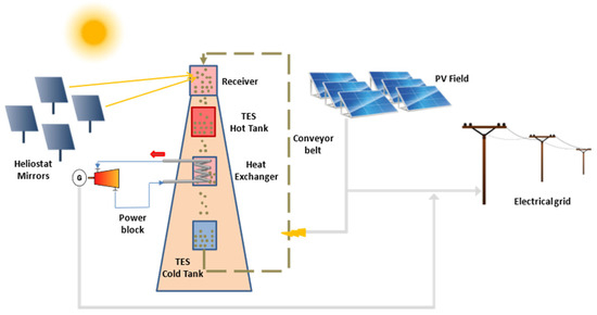
Figure 6.
Conceptual scheme of the considered hybrid CSP–PV plant.
The size of the PV system has been chosen to guarantee the coverage of the peak load (10 MWe), while any excess of electricity has been assumed to be converted into thermal energy to preheat the HTF, thus increasing the renewable energy exploitation and storage capability.
Through the modeling of the individual components of the integrated CSP/PV plant, a system model has been established to evaluate the capability of the hybrid plant to match a required load profile with a characteristic hourly curve. In detail, for the solar field, the arrangement of heliostats has been optimized to maximize efficiency in two specific locations (Spain and Australia) with the use of SolarPILOT software version 1.1. For the solar receiver, operating at 650 °C and consisting of a cavity system with a fluidized sand bed, a thermal efficiency function has been built in the Engineering Equation Solver (EES) environment based on the results of the thermo-fluid dynamic simulations. For the thermal storage system, consisting of two tanks (hot and cold) containing the HTF (sand), the time-dependent heat and mass balance equations have been elaborated in the EES environment. For the Power Block, a model has been developed based on a superheated steam Rankine cycle (maximum temperature: 580 °C) and a steam generator powered by hot sand.
For the PV plant, a theoretical model has been developed and implemented in Python, which receives as input the hourly data, the three components of solar radiation from the meteorological year Meteonorm, and the ambient temperature and provides as output the global radiation incident on the PV panels and, through an empirical correlation, the power produced by the PV field.
Through the integration of the abovementioned components, a quasi-steady state model of the complete system has been implemented in EES, which, based on time-dependent meteoclimatic data, allows the calculation of the thermal and electrical power generated by the hybrid plant on an hourly, monthly, and annual basis.
From the analysis, it was concluded that the CSP and PV systems operating in alternating mode (CSP during the night and PV during the day), with a nominal capacity of 10 MWe each, can cover, on a yearly basis, between 48% and 54% (in Spain), and between 50 and 57% (in Australia) of the grid’s load. It was also calculated that the grid’s load covered by a stand-alone PV plant with a peak power of 20 MWe (equivalent to the sum of the abovementioned PV–CSP sizes) is about 43% and 45% (referring to systems installed in Spain and Australia, respectively), which is well below the load coverage of the integrated PV–CSP plant.
Furthermore, considering an integrated CSP/PV system, in which any excess electricity from PV is converted into heat and stored through the CSP plant, the coverage of the grid’s load is between 50 and 56% (Spain) and between 53 and 60% (Australia), with an increase of 2–3% compared to the system with CSP and PV plants operating in alternating mode.
Therefore, it is evident that the effective integration between the two systems can have synergistic effects: not only the alternating operation of the CSP and PV systems can guarantee a 24-h producibility through the PVs during the day and through the CSP after sunset, but the effective functional integration of the two systems through electro-thermal dissipation can ensure a greater production of electricity, especially in the months characterized by good radiation. It is worth mentioning that the optimal size of the CSP–PV plants in an integrated system can only be identified through an exhaustive technical-economic analysis applied to specific territorial scenarios, which in the future could represent the development of this work.
3.2. MAGALDI Solid Particles Fluidized Bed Solar Receiver
Nowadays, interest from the scientific community has been growing for the third generation of CSP plants, with specific technology targets aimed to increase the technical performances and lower the LCOE, which are listed below:
- higher maximum temperatures achieved in the receiver (>700 °C);
- different types of HTF (innovation pathways with solid particles, molten salts, or gas receivers);
- a strong push toward the integration of TES with significant capacity;
- development of more efficient cycles, such as the supercritical CO2 Brayton conversion cycle, in comparison to the conventional Rankine steam cycle for electricity generation;
- higher cycle efficiencies than current ones (>50%);
- higher annual solar-electric efficiency (25–30%).
An alternative solution to the concept of a central tower with a single reflection of sunlight to the solar receiver/absorber, located at the top of the tower itself, is the double reflection system, also referred to as “beam-down.” This solution simplifies the construction of the tower and aims to reduce the CAPEX and OPEX of the system [64,65]. Double reflection consists of a double concentration of solar radiation, which is captured by a heliostat field, reflected back to a secondary reflector located at altitude, and then reflected back to the receiver located on the ground. This solution provides lower costs but requires significant precision in the design and construction of the reflectors and receiver. The concept of an SPT plant is shown in Figure 7a, while in Figure 7b, the beam-down system concept is shown.
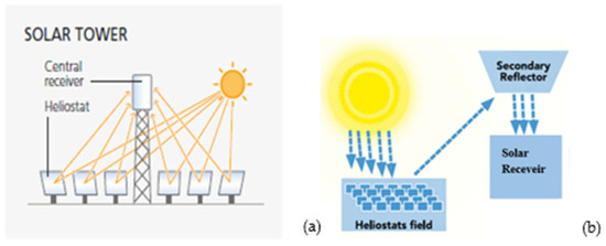
Figure 7.
(a) Concept of a central tower system SPT [66]; (b) Concept of a beam-down system.
Different prototype or demonstrator-type beam-down plants have been developed so far, although there are no commercial plants in operation yet. Table 3 shows the beam-down installations realized to date in Japan, Israel, UAE, Italy, and China.
Table 3.
Prototype/demonstrator implants with beam-down optics [67].
Beam-down technology involves greater system complexity for concentrating the radiation, both for anchoring the secondary reflector and for cleaning it. At the same time, however, this configuration provides greater advantages [68,69,70] in terms of reduced costs associated with ground receiver installation and plant operation, lower maintenance costs, modularity, flexibility of operation, and general benefits associated with the solar tower for high-temperature applications, such as solar thermochemistry.
Magaldi has been investing for more than a decade in the development of a CSP system called STEM®. A STEM® module consists of one heliostat field, a secondary beam-down reflector, an integrated fluidized-bed solar receiver, an air fluidization system, and an automation and control system. The solar radiation, captured by heliostats and concentrated on the secondary reflector, is directed into the central receiver containing a fluidized bed of silica sand, which also serves as a thermal storage tank, and where in-bed heat exchangers for steam generation are also arranged. The first prototype plant of 200 kWth (solar peak power) was installed at the Magaldi factory in Italy at the end of 2012. This was followed by the first demonstrator plant of 2 MW solar peak power, built at the A2A power plant in San Filippo del Mela (Messina, Italy) and inaugurated in 2016, as shown in Figure 8.
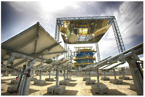
Figure 8.
Magaldi STEM® plant in San Filippo del Mela, Italy.
The STEM® demonstration plant has been operated for over 12,000 h, generating steam up to 550 °C and 50 bar, with temperatures reaching over 600 °C in the fluidized bed. The results of the validation of the current configuration of the STEM® were, therefore, an excellent basis for further development of the technology once the technical feasibility of using a fluidized bed of granular material for applications in the solar thermal and/or electrical (CST/CSP) field was demonstrated and validated. The solid particle bed, fluidized by an ascending current of air, has among its peculiar characteristics the ones listed below:
- ensuring high operational temperature, excellent thermal storage capacities, high diffusivity, and high heat transfer coefficients;
- optimal properties, thanks to which it is possible to transfer the captured solar energy in the first instance within the granular solid and, subsequently, to the HTF participating in the thermodynamic cycle.
The fluidized bed thus represents the heart of STEM® technology. Solid particle systems, due to the thermal characteristics of granular solid materials with high absorbance and heat capacity, enable higher operating temperatures (compared to molten salts) and, consequently, higher efficiency cycles, potentially leading to the replacement of the Rankine steam cycle with Brayton cycles with supercritical CO2 (sCO2) as the working fluid.
Based on the previously stated third-generation CSP guidelines and STEM® technology, Magaldi identified some lines of development necessary to achieve the goals set by the international scientific community for applications in the solar energy thermal and/or power sectors. New relevant components and an innovative system concept were developed over the years. Three specific directions for the development/optimization of STEM® technology, aimed at its coupling to high-temperature and high-efficiency conversion cycles, as well as to increase the plant capacity factor, were identified and explored, as indicated below:
- improvement of overall efficiency;
- hybridization of the solar primary energy source with other RES;
- a new innovative concept with integrated beam-down.
As a continuation of the successful test campaign of the STEM® demonstration plant, Magaldi introduced an innovative system configuration to consolidate the potential exploitation of high-temperature HTF for high-efficiency conversion cycles (e.g., sCO2).
Specifically, the innovative concept is based on a CSP tower configuration characterized by a solid particle fluidized bed as the solar capture technology, involving the use of an integrated beam-down in the bed and a hold on the top of the tower, as shown in Figure 9 and Figure 10. This new configuration retains the solid particles fluidized-bed solar receiver and includes the following:
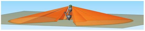
Figure 9.
Innovative concept of a system integrated beam-down with solid particle fluidized bed.
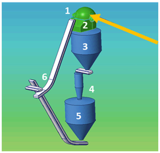
Figure 10.
Relevant components of integrated beam-down.
- (1)
- A beam-down reflector that is integrated into the receiver with a relevant optimized heliostat field.
- (2)
- A fluidized bed receiver that receives the concentrated solar power and releases “hot” particles to the downstream silo; the fluidized bed receiver is fed with “cold” particles by means of mechanical conveyors driven by Variable Frequency Drive (VFD) motors to adjust the material feeding rate according to the actual solar irradiance; the fluidized bed receiver, coupled with adjustable inlet material flow rate, provides sufficiently long residence time and control for releasing hot particles at uniform temperature.
- (3)
- A hot silo to store solid particles at high temperatures, which were released by the fluidized bed receiver; the hot silo is equipped with a solid particles extractor to feed the downstream heat exchanger with particles at the desired rate, according to the needed power load.
- (4)
- A heat exchanger located outside the receiver to allow the counter current heat exchange from the solid particles to the selected HTF (such as steam or sCO2). The solid particle mass flow rate from the hot tank to the counter-current heat exchanger can be adjusted through a dedicated feeder extractor. Moreover, the mass flow rate from the fluidized bed receiver to the hot tank is also adjustable.
- (5)
- A cold silo to store the particles exiting the heat exchanger at “low” temperatures.
- (6)
- Mechanical conveyors and elevators enclosed and thermally insulated (such as Magaldi Ecobelt conveyors) for recirculation of solid particles [71,72] from the cold silo to the receiver (during the day, charging phase), with minimum thermal losses and solid particles containment.
The innovative concept showcased in Figure 10 deviates from other CSP tower particle receivers as it includes a solid particle fluidized bed as a receiver, an integrated beam-down with lateral solar apertures, and a solid particles mechanical transport system, appropriate for conveying high-temperature particles, with high reliability and limited thermal losses. The fluidized bed works only as a solar receiver and allows high thermal diffusivity and extended residence time for irradiating particles, resulting in a homogeneous temperature distribution and an efficient regulation of the particles’ outlet temperature. In this configuration, the thermal storage system with two tanks (hot/cold) is placed below the fluidized bed solar receiver. Unlike the in-bed heat exchanger used in the system illustrated in Figure 8, the high-temperature HTF is produced by a solid particle to the HTF counter-current heat exchanger, which was fed by the hot tank located upstream, releasing cooled particles to the downstream cold tank. This configuration, in comparison with the CSP fluidized bed plant in Figure 8, allows for continuously generating the HTF at a temperature close to the solid particle maximum temperature [73].
Several activities were carried out to focus on the most critical aspects and components of the proposed concept, with the aim of defining design and materials, as well as to improve and de-risk their operation, as indicated below:
- Computational Fluid Dynamics (CFD) modeling for evaluating the solid particle mass flow fields and residence time in the fluidized bed receiver, along with Finite Element Method (FEM) modeling of the integrated beam-down radiant cavity with efficiency evaluations.
- Design and realization of new wireless, “self-powered” heliostats to evaluate the potential of electrical wiring elimination in the heliostat fields.
- Thermo-mechanical analyses of high-temperature components of the solar receiver fluidization line, which undergo intense thermal fatigue cycles.
- Development of secondary reflectors, suitable to operate under highly concentrated solar power and high temperature, based on ceramic materials with high emissivity as well as on metal substrate coatings realized by Physical Vapour Deposition (PVD) techniques for high reflectivity.
- Thermo-fluid-dynamics characterization of several granular materials aimed to evaluate the particle types to be most suitably used in the fluidized bed receiver in terms of high absorbance, heat capacity, density, low fluidization speed as well as large availability.
- Selection and characterization of electric heating elements suitable for heating the selected type of solid particles by allowing hybridization of the TES charge.
The research activities allowed for an in-depth study of several features of the technology in terms of capture efficiency, basic geometric configurations, characterization and optical design of the heliostat field, and experimentation on innovative materials. In particular, among the expected improvements compared to the STEM® configuration as realized (Figure 8), the following can be highlighted:
- The reduction of approximately 10% in reflectivity losses thanks to the new integrated beam-down system.
- The presence of an external solid particle/HTF counter-current heat exchanger suitable for achieving high conversion efficiencies and power generation, thanks to the possibility of reaching high temperatures and pressures of the HTF. For example, novel sCO2 cycle and corresponding key components are eagerly desired to achieve efficient thermal-electric conversion with peak temperatures of cycle expected to be over 700 °C and design cycle efficiency over 50%, compared to conventional 38–44% of the steam cycle today in operation, with an increase of about 20% [62]. Considering the combined reduction of the optical losses and the increase in the cycle efficiency, it is possible to achieve an increase in the overall plant efficiency by up to 30%.
- Auxiliary consumption associated with a fluidized bed can potentially be reduced by using the fluidized bed only in the overhead solar receiver, whereas hot and cold particle storage silos do not need fluidization. As an example, reference can be made to the parallel work conducted in the SOLARGRID project [73]: the adoption of the proposed configuration allows reducing the mass of the bed to be fluidized by a range of 85–90%, bringing a significant proportional reduction of relevant power needed for the auxiliaries (blower and fan). On the other hand, considering also the effect of additional power needed by the proposed configuration for mechanical recirculation of the solid particles from the cold silo to the top receiver, auxiliary power saving can be estimated in a range of 70–80%.
The hybridization of the charge of CSP with green electricity produced by intermittent RES is indeed an additional feature to be deployed. Taking advantage of using, at peak hours, the surplus power from PV and wind to charge, with electrical heaters, the CSP plant, allowing an increase in its capacity factor at a relatively low cost. In addition, the hybridization of CSP with PV and wind helps reduce the land required for the CSP heliostat field near the utility, thanks to the possibility of using power from PV or wind plants not co-located at the utility site.
The proposed new concept aims to reduce the LCOE due to the combination of several benefits, in terms of increased system operational continuity and overall efficiency, obtainable thanks to (i) the adoption of the solid particles fluidized bed receiver, with integrated beam-down, (ii) the associated high temperature of the evolving fluid with potential coupling with high-efficiency power block, such as sCO2 and, (iii) the hybridization of energy charging with low-cost intermittent RES. It is possible to estimate that the LCOE value could reach 5 cents € per kWh in 2030.
Finally, the solution with integrated beam-down would require further investigation. Advanced thermo-electric conversion cycles to sCO2 are promising but still under development; for instance, the sCO2 heat exchanger that works at the aforementioned temperature and pressure values. Moreover, it is necessary a further optimization of the systems for moving and recirculating solid particles (from the cold tank to the receiver) and for dosing them (in particular between the receiver and the hot tank and between the hot tank and the cold silo), with the aim to increase the reliability while minimizing the thermal losses.
3.3. Eni’s Parabolic trough Collector CSP3
As well known in the scientific community, the cost of collectors is an important share of the total investment costs of a CSP plant with PTC technology. In order to be effective, the cost reduction cannot be based on a single technical aspect, but it must be diversified on many points. With the design of the new PTC CSP3, Eni has contributed to technical and economic improvements of the CSP technology toward its competitiveness, with the simplification of the PTC structure with components easy to produce and assemble, keeping high optical efficiency as required and already obtained in the state-of-the-art technology.
Eni’s PTC CSP3 is the evolution of the PTC CSP2, the first operating prototype designed with the collaboration of the Massachusetts Institute of Technology and Politecnico di Milano (Figure 11, [74]). The main features of that prototype included an extremely light-bearing structure with a large saving of steel elements, the use of reflective polymer film applied on a thin metal support as a reflective surface, and a multi-point distributed actuation system along the solar collector assembly (SCA). The 12-m long PTC unit with a 6-m aperture was designed with a bearing structure composed of simple galvanized steel elements, such as box profiles with square or rectangular sections. Moreover, the extensive use of structural adhesive for joining most of the parts of the structure allowed a lighted structure compared with the ones using bolts or rivets, keeping a good stiffness and simplifying the assembly of parts.
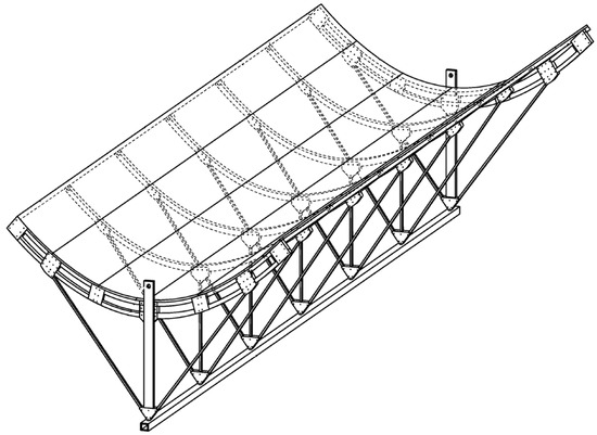
Figure 11.
PTC CSP2 concept (extracted from [74]).
The first prototype of PTC CSP2, called CSP2.0 (Figure 12), was assembled and subjected to a full mechanical testing campaign at the laboratories of Politecnico di Milano [75]. Further studies carried out in collaboration with Politecnico di Milano included structure modeling through the use of Finite Element Analysis (FEA) simulations [76] and 3D optical measurements through laser-scanning [77] with respect to the desired optical performance [78]. The second prototype, called CSP2.1 (Figure 13), was the first operative Eni’s CSP device, and it was recently tested at the first Eni’s CSP pilot plant. The prototype tracks the sun using hydraulic actuators and the correspondent thermal power is about 50 kWth.
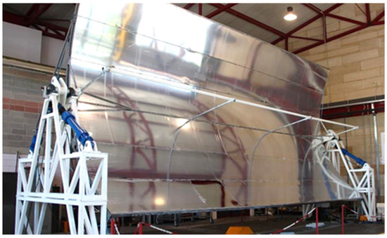
Figure 12.
PTC CSP2.0 prototype testing at Politecnico di Milano.
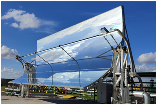
Figure 13.
PTC CSP2.1 prototype testing at Eni’s CSP pilot plant.
The parts procurement, assembly, transport, and first test operations of the PTC CSP2 were used as a basis for the optimization studies carried out within the research project of CSP3, which is designed with the same size and thermal power. Within this project, various technical-economic aspects of the bearing structure and the reflective surface of the collector were analyzed. As with its predecessor, the CSP3 will also have a first working prototype (CSP3.1) in the same CSP pilot plant, leading to about 100 kWth in the power of the solar testing facility (Figure 14). In the same pilot plant upgrade, a thermocline TES unit based on concrete and a steam microturbine will also be installed and tested within the hybrid functioning of the facility.
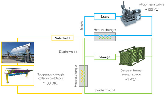
Figure 14.
Schematization of Eni’s CSP pilot plant.
The design of the CSP3 had the contribution of EniProgetti, a subsidiary engineering company of Eni, regarding analyses and verifications of the CSP3.1 prototype and of the Politecnico di Milano, regarding CFD analyses. Among the various improvements from the CSP2 experience, it was also found that the multi-point actuation strategy of the SCA could not benefit from the overall cost reduction compared to the single actuation point strategy or from the use of less steel for the collectors, especially when the volume of collectors is not large. Indeed, a distributed actuation strategy forces a greater effort on the synchronism of the motors, and it increases the risk of breakage of the sections of receiver tubes rigidly connected through welding.
Furthermore, Eni’s research on CSP has also led in parallel to the development of a new type of collector, called CSP Evo (Figure 15, [79]), in which the use of a single actuation point along the SCA was re-established with the increase in torsional stiffness by means of a torque tube, typical of the state-of-the-art PTC technology.
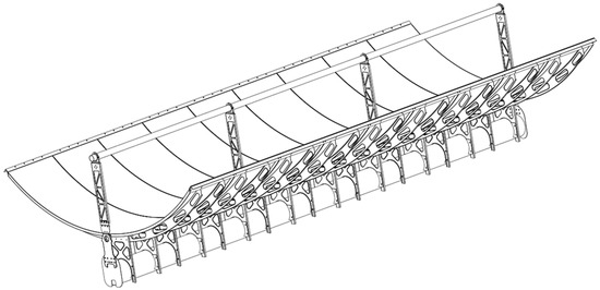
Figure 15.
PTC CSP Evo concept (extracted from [79]).
The experience gained on the CSP2 and the development of the CSP Evo collector ultimately led to the features of the new CSP3. The peculiar and innovative characteristics of Eni collectors are the use of reflective polymer film applied on a thin metal support for reducing costs and avoiding the presence of fragile glass mirrors and the use of structural adhesive for connecting the parts of the bearing structure. The reflective film can be produced by various providers. The best product experimented by Eni achieved a total solar reflectance higher than 93% (from 3 M measurements, test method ASTM E309, G173) and a specularity higher than 97% (from 3 M measurements, test method D&S 15 mrad, 660 nm).
Currently, a very good value of the peak optical efficiency of PTCs is considered to be in the range of 73–82% [80], which is the value of the best products available in the market. Thanks to the employment of this reflective polymeric film, the target peak optical efficiency of the new CSP3 is 80%, which represents a large improvement considering the expected cost reduction.
Moreover, like the CSP Evo concept, a torque tube was adopted to increase the torsional stiffness of the structure. This last feature is linked to the possibility of having an SCA up to 150 m in length with a single actuation point. ENEA guidelines on the design of PTCs [81,82,83,84] were followed for the design in order to maintain adequate efficiency levels. All the requirements imposed by current regulations and techniques of good engineering practice [85,86,87,88,89,90,91,92,93,94,95,96] were used for the design of the PTC CSP3, considering Southern Italy as a place of installation and its correspondent wind, snow, and earthquake loads foreseen by the law. However, the objective of the design was also to have a basic PTC design valid for CSP plants located in places with different geographical and environmental characteristics. The resulting PTC CSP3 design peculiarities involve a bearing structure composed of simple production carpentry parts made in galvanized structural steel, such as parabolic ribs, consisting of simple curved metal profiles with a rectangular section, to reinforce the back of the reflective part consisting of thin metal sheets (Figure 16). The mechanical assembly was confirmed without the use of specialized labor (e.g., welders). In particular, the assembly of the structure can be performed by means of a parabolic construction jig with the concavity of the PTC facing downwards. The use of structural adhesive is reduced compared to CSP2; it is used only for the joint between the reflective sheets and the ribs, thus reducing assembly time.
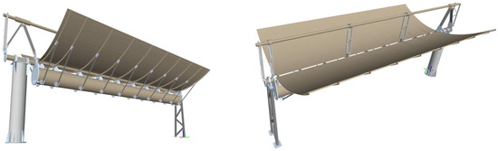
Figure 16.
Constructive scheme of Eni’s PTC CSP3.
The parabolic jig allows the realization of several PTC units, and more than one jig can be used in parallel to increase the production capacity according to the desired realization times and investment costs. The PTC rotation system allows an angular excursion of ±110°. The safety position of the collector is set at −110° or +110° depending on the wind direction so that the collector always exposes the back side against the heavy wind. This position is the best compromise between the aerodynamic actions generated on the structure and the best protection of the receiver tube and the reflective film. Furthermore, design choices were made toward the technical-economic optimization of the system. In particular, the torsional stiffness of the system was increased, up to the possibility of installing 12 PTC units on the same SCA through the introduction of a torque tube. This part is connected to the ribs via the intermediate connecting plates and braces. Finally, all remaining parts were further optimized, simplifying geometries and production techniques, reducing the total number of components, and homogenizing different parts to simplify procurement and production costs. For instance, parts already available in catalogs of the major steel components producers were preferred. Further optimization strategy involved the relaxation of some stringent specifications not involved in the resultant efficiency of the system and the obtainment of the maximum benefits in case of production on large volumes with the possible industrialization process. Finally, all phases of the PTC assembly were revised in order to reduce time and costs, for instance, considering the better handling of parts, the reduction in the number of different components, the ease of access for reaching all parts, and the parallelization of assembly phases.
For the correct definition of the fluid dynamic actions underlying the sizing of the CSP3 according to the regulations, it was necessary to study the related phenomena through CFD analyses with the software Ansys Fluent version 18.2. Various combinations of wind speeds and rotation angles of PTCs were considered for the CFD analyses in order to simulate better all the pressure conditions loading the bearing structures of PTCs. Moreover, a large domain for simulations consisting of several rows of collectors and a windbreak barrier in front of the first row (Figure 17a) was modelled. A rotating fine mesh was created (Figure 17b), and the pressure values for the most critical PTC in the solar field were calculated (Figure 17c), as well as the wind actions acting on the structures at different rotation angles of the PTCs. The design of the CSP3 bearing structure did not include only specific FEA calculations derived from CFD analyses for the evaluation of maximum stresses acting on the structure but also several other analyses and verifications, such as those inherent to the stability of elements, buckling effects, punching of nodes, bolted joint checks, seismic effects, lifting and transportation, vortex shedding, temperatures differential deformations, rotations and deformations of the reflective surface and consequent efficiency estimation (Figure 17d).
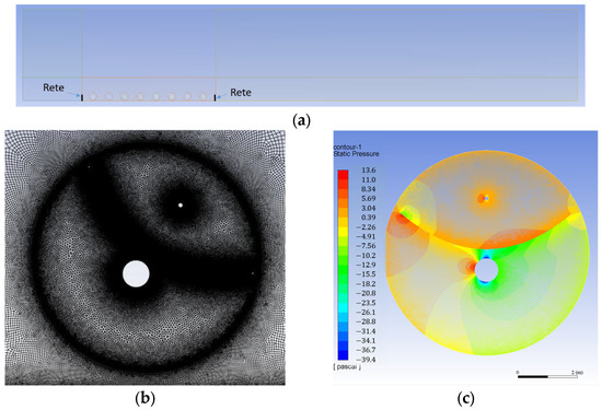
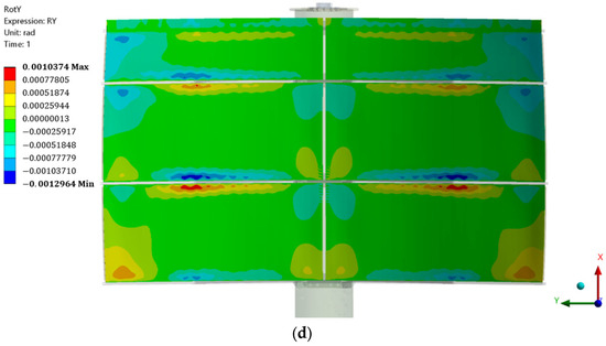
Figure 17.
(a) CFD simulation domain with Ansys Fluent; (b) Details of the mesh used a single PTC for the CFD analyses; (c) Example of pressure results of CFD analyses; (d) Example of resulting rotations of the reflective surface from FEA with Ansys.
The analyses were carried out in accordance with NTC 2018 and Eurocode 3 [85,96], and some of them were performed with the use of software Sesam DNV and Ansys.
For the sizing of the actuation system, it was necessary to calculate all the torque components acting on the bearing structure. These include wind momentum actions and all effects caused by the eccentricity of their own weight, the lift and drag forces, the bearing friction effects, and the snow. The calculation was carried out according to all the angles of the positioning of the collector during its operating life.
The ultimate goal of this project was the development of a more competitive product in technical and economic terms that would benefit both small and large CSP plants. The main challenge is to confirm the cost reduction related to both the previous CSP2 collector and the current benchmark of the market.
A detailed economic analysis revealed a cost reduction of the PTC structure ranging from 15% to 30% with the new CSP3 compared with the previous CSP2, depending on the quantity of collectors to be produced and hence the size of the solar field. The target is to achieve a specific cost of the solar field lower than 120 €/m2, which is below most of the current commercial PTCs [80]. The time of construction of CSP3 can be reduced by 70% as compared to CSP2 by parallelizing assembly tasks.
Moreover, the experimental measurements on the prototype will also be carried out to confirm the optical and thermal efficiency of the system. Results are expected in 2024.
Eni’s activity had the aim not only of increasing internal know-how on CSP technology in order to support the integration of CSP technology into its business but also to actively participate in the development of the CSP technology in Italy and in the countries in which Eni operates, collaborating proactively with all the main stakeholders.
3.4. New LFR Configuration of IDEA S.r.l.
The approach to the development of a new LFR configuration in the SOLARGRID framework has allowed the identification and development of several specific solutions that address the technical/economic barriers previously described in Section 2.1.2 and summarised in Figure 3. In particular, the IDEA company has completely reviewed the design of a previous LFR model (LFR1832), which was successfully installed in three experimental sites, serving polygenerative setups [97]. These innovative strategies have been applied to high-temperature CSP collectors and smaller SHIP systems.
The first techno-economic barrier to be addressed is the high cost of fabrication of the primary mirrors used, which were manufactured in curved tempered glass to achieve high optical performances. Each mirror has to be slumped at high temperatures in expensive molds, one for each radius of curvature to be achieved.
Different reflection materials to be eventually applied on cheap surfaces have been taken into consideration, with the aim of identifying a better compromise between cost and optical performance. Moreover, various configurations of the mounting frame have been tested with the objective of obtaining acceptable and stable curvatures by the mechanical bending of flat glass mirrors. As a matter of fact, a major saving of about 50% in the manufacturing cost of the primary mirrors could be envisaged if the expensive process of slumping the different curvatures could be substituted by adjustable mechanical bending. Due to the specific properties of glass, the possibility of mechanically bending a sheet of glass depends upon its thickness and width. Preliminary tests confirmed the feasibility of this approach, giving precise indications in terms of the minimum width of the primary mirrors. The general optical design of the collector was reviewed by taking into account this boundary condition and having in mind the second techno-economic barrier listed in Figure 3, i.e., the need of meeting dimensional constraints to minimize waste.
The third innovation component is aimed at obtaining a higher concentration ratio and a better distribution of reflected radiation on the absorber. For this aim, a new optical geometry, and in particular a new secondary reflector, has been developed using Non-Imaging Optics (NIO) methodologies. This approach ensures optimal concentration and proper distribution of the radiation intercepted by the primary optics on the absorber by the secondary reflector. A double-tube configuration (U-bent receiver) has also been adopted in order to enlarge the target, resulting in a further improvement in terms of intercepted radiation as well as a better hydraulic configuration (inlet and outlet of the hydraulic circuit placed on the same side). At first, the methodology was tested in the design of a receiver that could be integrated into the previous LFR collector without changes in the primary optics [98]. In the second stage, the NIO design strategy was applied to the design of totally new systems that would consider the geometrical constraints arising from the manufacturing strategies (i.e., mechanical bending and minimization of waste).
The optical design process was, therefore, contextualized in the more general path of optimization of the entire collector (design methodology according to the V-model) [99]. The iteration of the optical and general design was constantly taking into account the industrialization challenges, including the need to maximize the number of standard components.
Finally, the curvature of the primary mirrors was achieved through a novel mounting frame that allows a very precise deformation of flat glass mirrors along the main axis. This results in reflectors with focal lengths appropriate for the mirror employed in each of the two applications, CSP (thickness 3 mm, width 1.000 mm) and SHIP (thickness 3 mm, width 650 mm). The deformation turns out to be controllable during mounting. Thanks to this innovation, reflectors can be easily assembled directly at the installation site from simple prefabricated metal frames and flat mirrors (Figure 18), with further cost savings due to the optimization of transportation volumes. The new mid-temperature collector has been engineered and is now marketed under the LFR1265U label.
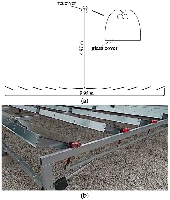
Figure 18.
(a) Final geometry of the new collector LFR1265U, with 12 primary mirrors 650 mm wide. As evidence, its characteristic atmospheric receiver with 2 adjacent absorber tubes in the NIO-designed cavity. (b) Mechanically bent primary mirrors of the new LFR1265U collector developed by IDEA S.r.l. undergoing tests in a complete module. Note the novel, patent-pending mounting frames that embed the adjustable curving mechanism.
Figure 18a,b present the final configuration of the LFR1265U collector and the detail of the novel primary optics, respectively, characterized by the patent-pending frames that are mechanically curving the mirrors.
The optical and structural design of both collectors takes into account the optimal dimensions for waste reduction in all elements (glass mirrors, secondary metal reflectors, metal profiles, sheet metal).
Finally, a new solar tracker for linear focus CSP and Fresnel systems has been designed by the University of Florence to optimize the orientation of mirrors or lenses to concentrate sunlight onto the linear receiver. The objective is to address the fourth techno-economic barrier through the achievement of good tracking accuracy with cheap and liable electronic components that might substitute expensive Programmable Logic Controller (PLC)-based tracking systems. In the novel approach, each LFR collector is equipped with a tracking microcontroller and a solar pointer sensor. Both components have very low industrial costs (tens of euros), well below the cost of an equivalent PLC-based system. The single node is connected to a master supervisory and data logging device through the 485 bus and MODBUS protocol. This configuration makes each manifold autonomous in the tracking procedure and increases the possibility of tuning to correct mounting inaccuracies. The distributed architecture of the control unit also improves the overall resilience of the system.
The developed tracker system has been optimized for operation with linear actuators equipped with position sensors and analog signals (voltage, 4–20 mA, or potentiometer) for use in a closed loop. The specific need to create a system to be replicated on each solar module, making the latter completely autonomous, required a development that would mainly focus on robustness and cost. The choice fell on a board with a microprocessor system able to control two motors. In such a way, the same hardware can thus be used for both two-axis trackers and linear systems. In this last case, the two motors are usually mounted at the beginning and end of the string; a series of specific algorithms allow their synchronization for the correct tracking of the sun, keeping the mirrors perfectly aligned, compensating for friction and aging of the mechanics. It consists of sensors that detect the position of the sun (Figure 19) and control units (Figure 20) that process the sensor data and provide the output for the motors controlled individually based on the real position feedback.
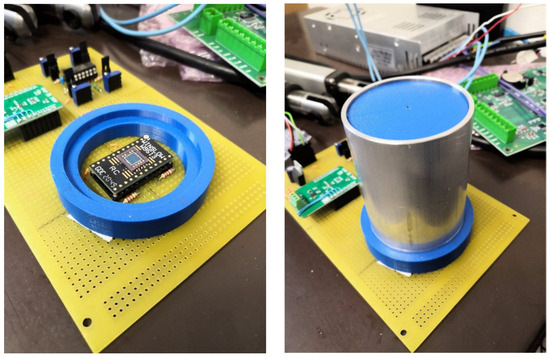
Figure 19.
Sensor POINT-FOCUS.
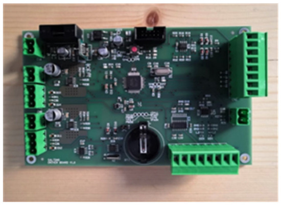
Figure 20.
Control Unit.
In the first daily start-up phase, the theoretical position of the sun is used to allow the sensor to lock onto the sun, after which the system automatically proceeds in a closed loop. The tracker then continuously updates the position of the mirrors or lenses to maintain optimal alignment with the sun and ensure accurate focusing of sunlight onto the linear receiver.
It is important to note that the design of the solar tracker can vary depending on the specific CSP technology and installation requirements. Each type of CSP system (PT, LFR, etc.) may have different trackers and specific configurations to accommodate its unique design and operational needs.
The tracking system was designed to be easily adapted to the different mechanics and, above all, the geometries used to move the mirrors. A configuration software (SW) menu allows you to enter the geometric data of the linkage and the engine data. Finally, a start-up phase allows the system to create the appropriate geometric references and learn the data for the next check. A simple digital signal allows you to operate the focus command or the defocus/sleep command.
Finally, a specific communication (ModBus) allows the monitoring of each single module or solar collector and the commanding of their actions. A specific SW was proposed for the industrial structure. Table 4 summarizes the improvements achieved in performance and cost through the redesign of the mid-temperature collector in the SOLARGRID project by IDEA S.r.l.
Table 4.
Performance and cost improvements achieved by LFR technology innovation.
The adoption of the new receiver also offsets the costs arising from the frequent cleaning of the glazed absorber and the secondary optics, which were fully exposed to soiling. The preliminary estimation of such a reduction in OPEX is equal to 50%, which represents a yearly saving of about 30 Euro/m2.
The main current challenges faced with regard to the full industrialization of the new LFR collector are represented by the validation of the atmospheric receiver in terms of dimensional stability and the resistance of the coating in air. Also, the mechanical curvature of primary mirrors should be proven stable in time.
One of the envisaged future developments is represented by the possibility of hybridization of the LFR collector by the installation of tracked PV modules on the same structure supporting the primary optics. Tests have been conducted in order to achieve a cost-effective integration by the utilization of the same mounting frames and tracking system for both the mirrors and the PV panels. For this purpose, it is essential that mirrors and PV modules have similar dimensions and weights.
4. Conclusions
A potential solution to limit the huge intermittence and fluctuation in power generation from renewable energy sources is represented by CSP technology, and even more so when integrated with long-term TES. In fact, predictability and reliability of production and dispatchability are achievable thanks to the integration with thermal storage, high efficiency in terms of costs, low use of critical raw materials, and the potential employment of recyclable materials with low environmental impact, representing the main advantages of the CSP technology. The present work aims to discuss and present the advantages deriving from the development of innovative industrial solutions for CSP components and systems developed in the Italian project SOLARGRID. In detail, following an exhaustive analysis of the main CSP technologies and their future perspectives, the work discusses the enhancement of flexibility and the increased reliability achieved by coupling CSP and PV technologies, the proposed new concept relative to the STEM technologies of Magaldi Power S.p.A., the advanced parabolic trough collector realized by Eni S.p.A., and the new LFR concept developed by IDEA S.r.l. All these innovative solutions aimed to reduce the LCOE and to improve the technical performance of CSP technologies, making them competitive with other RES for electrical and thermal energy production. The analysis elaborated on the potential barriers to the development of CSP technology in Europe highlights that a mix of complementary policy measures is required to either activate drivers or mitigate barriers to CSP deployment in the future. The adoption of long-term targets, ensuring predictable changes in the remuneration for new plants, and avoiding retroactive changes for existing plants are considered by key stakeholders to be essential elements for CSP deployment in the future. The maturity of the technology and knowledge and experience accumulation are also key drivers of the technology. Specific R&D actions to follow, which allow the enhancement of CSP technology, are also identified by highlighting policies to encourage public–private partnerships, the cooperation between the industrial sector and the RD&D sector on deployment projects, and the support and collaboration at the national and international levels, which are also essential for removing barriers to the deployment of this technology.
Author Contributions
Conceptualization, V.P., M.D.S. and C.C.; Methodology, V.P.; Validation and formal analysis, V.P., W.G., M.D., M.L., M.D.L., F.B., G.G., C.B., S.C., F.N. and F.M.M.; Writing—original draft preparation and writing—review and editing, V.P., M.D.S, C.C., W.G., M.D., M.L., M.D.L., F.B., C.B., S.C., F.N., F.M.M. and G.G.; Project administration: C.C. and G.G.; Supervision, G.G. All authors have read and agreed to the published version of the manuscript.
Funding
This research was funded by the Research and Innovation Project “Solargrid: Sistemi sOlari termodinamici e fotovoLtaici con Accumulo peR co-GeneRazIone e flessibilità Di rete”—cod. ARS01_00532. The project has been jointly funded by the European Union and the Italian Research and University Ministry (MIUR) under the Programma Operativo Nazionale “Ricerca e Innovazione” 2014–2020 (PON “R&I” 2014–2020).
Data Availability Statement
Not applicable.
Conflicts of Interest
The authors declare no conflict of interest.
Abbreviations
| Acronym | Meaning |
| ATES | Aquifer Thermal Energy Storage |
| BTES | Borehole Thermal Energy Storage |
| CAPEX | CAPital EXpenditure |
| CFD | Computational Fluid Dynamics |
| CSP | Concentrating Solar Power |
| CST | Concentrating Solar Thermal |
| DNI | Direct Normal Irradiance |
| ECs | Energy Communities |
| EES | Engineering Equation Solver |
| FEA | Finite Element Analysis |
| FEM | Finite Element Method |
| GWTES | Gravel-Water Thermal Energy Storage |
| HTF | Heat Transfer Fluid |
| HWTES | Hot Water Thermal Energy Storage |
| ISCC | Integrated Solar Combined Cycle |
| LCOE | Levelized Cost Of Electricity |
| LCOH | Levelized Cost Of Heat |
| LFR | Linear Fresnel reflector |
| MENA | Middle East and North Africa |
| NIO | Non-Imaging Optics |
| OPEX | OPerating Expenditure |
| ORC | Organic Rankine Cycle |
| PCU | Power Conversion Unit |
| PLC | Programmable Logic Controller |
| PT | Parabolic Trough |
| PTC | Parabolic Trough Collector |
| PV | Photovoltaic |
| PVD | Physical Vapour Deposition |
| RES | Renewable Energy Sources |
| SCA | Solar Collector Assembly |
| SHIP | Solar Heat for Industrial Processes |
| SOLARGRID | Thermodynamic and Photovoltaic Solar Systems with Storage for co-generation and net-work flexibility |
| SolarPACES | Solar Power and Chemical Energy Systems |
| STEM® | Solar Thermo Electric Magaldi |
| STES | Seasonal Thermal Energy Storage |
| SPT | Solar Power Tower |
| SW | Software |
| R&D | Research and Development |
| RD&D | Research, Development, and Deployment |
| TES | Thermal Energy Storage |
| VFD | Variable Frequency Drive |
References
- Amanatidis, G. European Policies on Climate and Energy towards 2020, 2030 and 2050; European Parliament: Strasbourg, France, 2019. [Google Scholar] [CrossRef]
- Di Somma, M.; Graditi, G. Challenges and opportunities of the energy transition and the added value of energy systems integration. In Technologies for Integrated Energy Systems and Networks; Wiley: Hoboken, NJ, USA, 2022; pp. 1–14. [Google Scholar]
- Jin, L.; Rossi, M.; Ciabattoni, L.; Di Somma, M.; Graditi, G.; Comodi, G. Environmental constrained medium-term energy planning: The case study of an Italian university campus as a multi-carrier local energy community. Energy Convers. Manag. 2023, 278, 116701. [Google Scholar] [CrossRef]
- Morch, A.; Di Somma, M.; Papadimitriou, C.; Sæle, H.; Palladino, V.; Ardanuy, J.; Conti, G.; Rossi, M.; Comodi, G. Technologies enabling evolution of Integrated Local Energy Communities. In Proceedings of the IEEE International Smart Cities Conference (ISC2), Pafos, Cyprus, 26–29 September 2022. [Google Scholar] [CrossRef]
- Piazza, G.; Delfino, F.; Bergero, S.; Di Somma, M.; Graditi, G.; Bracco, S. Economic and environmental optimal design of a multi-vector energy hub feeding a Local Energy Community. Appl. Energy 2023, 347, 121259. [Google Scholar] [CrossRef]
- Papadimitriou, C.; Di Somma, M.; Charalambous, C.; Caliano, M.; Palladino, V.; Cortés Borray, A.F.; González-Garrido, A.; Ruiz, N.; Graditi, G. A Comprehensive Review of the Design and Operation Optimization of Energy Hubs and Their Interaction with the Markets and External Networks. Energies 2023, 16, 4018. [Google Scholar] [CrossRef]
- Yan, B.; Di Somma, M.; Luh, P.B.; Graditi, G. Operation Optimization of Multiple Distributed Energy Systems in an Energy Community. In Proceedings of the IEEE International Conference on Environment and Electrical Engineering and 2018 IEEE Industrial and Commercial Power Systems Europe (EEEIC/I&CPS Europe), Palermo, Italy, 12–15 June 2018; pp. 1–6. [Google Scholar] [CrossRef]
- Haase, M.; Wulf, C.; Baumann, M.; Rösch, C.; Weil, M.; Zapp, P.; Naegler, T. Prospective assessment of energy technologies: A comprehensive approach for sustainability assessment. Energy Sustain. Soc. 2022, 12, 20. [Google Scholar] [CrossRef]
- Goyal, N.; Aggarwal, A.; Kumar, A. Concentrated solar power plants: A critical review of regional dynamics and operational parameters. Energy Res. Soc. Sci. 2022, 83, 102331. [Google Scholar] [CrossRef]
- Pazheri, F.R.; Othman, M.F.; Malik, N.H. A review on global renewable electricity scenario. Renew. Sustain. Energy Rev. 2014, 31, 835–845. [Google Scholar] [CrossRef]
- IRENA International Renewable Energy Agency. Renewable Energy Statistics 2022; IRENA International Renewable Energy Agency: Abu Dhabi, United Arab Emirates, 2022. [Google Scholar]
- Schmela, M.; Rossi, R.; Lits, C.; Chunduri, S.K.; Shah, A.; Muthyal, R.; Moghe, P.; Kalam, S.; Jamkhedkar, A.; Goel, S.; et al. Advancements in solar technology, markets, and investments—A summary of the 2022 ISA World Solar Reports. Sol. Compass 2023, 6, 10004. [Google Scholar] [CrossRef]
- Blanc, P.; Espinar, B.; Geuder, N.; Gueymard, C.; Meyer, R.; Pitz-Paal, R.; Reinhardt, B.; Renné, D.; Sengupta, M.; Wald, L.; et al. Direct normal irradiance related definitions and applications: The circumsolar issue. Sol. Energy 2014, 110, 561–577. [Google Scholar] [CrossRef]
- Lovegrove, K.; Stein, W. (Eds.) Concentrating Solar Power Technology Principles, Developments and Applications; Woodhead Publishing Series in Energy; Woodhead Publishing: Sawston, UK, 2012; ISBN 978-1-84569-769-3. [Google Scholar]
- Mongibello, L.; Bianco, N.; Naso, V.; Fucci, R.; Di Somma, M. Numerical characterization of a highly concentrated solar radiation sensor based on an inverse method. Sol. Energy 2015, 111, 407–417. [Google Scholar] [CrossRef]
- Ciavarella, R.; Di Somma, M.; Graditi, G.; Valenti, M. Congestion Management in distribution grid networks through active power control of flexible distributed energy resources. In Proceedings of the IEEE Milan PowerTech, Milan, Italy, 23–27 June 2019; pp. 1–6. [Google Scholar] [CrossRef]
- Alami, A.H.; Olabi, A.G.; Mdallal, A.; Rezk, A.; Radwan, A.; Rahman, S.A.H.; Shah, S.K.; Abdelkareem, M.A. Concentrating solar power (CSP) technologies: Status and analysis. Int. J. Thermofluids 2023, 18, 100340. [Google Scholar] [CrossRef]
- Machinda, G.T.; Chowdhury, S.; Arscott, R.; Chowdhury, S.P.; Kibaara, S. Concentrating Solar Thermal Power Technologies: A review. In Proceedings of the Annual IEEE India Conference, Hyderabad, India, 16–18 December 2011; pp. 1–6. [Google Scholar] [CrossRef]
- Buscemi, A.; Lo Brano, V.; Chiaruzzi, C.; Ciulla, G.; Kalogeri, C. A validated energy model of a solar dish-Stirling system considering the cleanliness of mirrors. Appl. Energy 2020, 260, 114378. [Google Scholar] [CrossRef]
- National Renewable Energy Laboratory. Concentrating Solar Power Projects n.d. Available online: https://solarpaces.nrel.gov (accessed on 18 October 2023).
- SOLARGRID Project (Thermodynamic and Photovoltaic Solar Systems with Storage for Co-Generation and Network Flexibility). Available online: https://www.solargrid-project.eu/ (accessed on 18 October 2023).
- Crescenzi, T.; Falchetta, M.; Fontanella, A.; Metelli, E.; Miliozzi, A.; Spinelli, F.; Sipione, L. Opportunità di Applicazione Delle Tecnologie Solari Termodinamiche in Italia; ENEA: Stockholm, Sweden, 2016; ISBN 978-88-8286-335-7. [Google Scholar]
- De Iuliis, S. Solare Termico a Concentrazione; (SIMTE (enea.it)); ENEA: Rome, Italy, 2018. [Google Scholar]
- Murphy, C.; Sun, Y.; Cole, W.; Maclaurin, G.; Turchi, C.; Mehos, M. The Potential Role of Concentrating Solar Power within the Context of DOE’s 2030 Solar Cost Targets; NREL/TP-6A20-71912; NREL: Golden, CO, USA, 2019. [Google Scholar]
- Flamant, G. Concentrating Solar Thermal Energy Fundamentals and Applications; Iste/Hermes Science Pub: London, UK, 2022; ISBN 978-1-78945-079-8. [Google Scholar]
- Balog, I.; Caputo, G.; Spinelli, F.; Benedetti, A.; Siviero, R. Caratterizzazione del Potenziale Solare Radiativo Dell’Italia Centro-meridionale. Report RdS/PTR2020/250. 2020. Available online: https://www2.enea.it/it/Ricerca_sviluppo/documenti/ricerca-di-sistema-elettrico/adp-mise-enea-2019-2021/solare-termodinamico/report-rds_ptr_2020_250.pdf (accessed on 19 October 2023). (In Italian).
- Beurskens, L.W.M.; Hekkenberg, M. Renewable Energy Projections as Published in the National Renewable Energy Action Plans of the European Member States 2011; European Environment Agency: Copenhagen, Denmark, 2011. [Google Scholar]
- Giaconia, A.; Grena, R.; Russo, V. Definizione Delle Configurazioni di Impianti Ibridi CSP/PV più Idonee All’Interfacciamento con il Sistema di Distribuzione di Energia Elettrica Nazionale. Report RdS/PTR2019/089. 2019. Available online: https://www2.enea.it/it/Ricerca_sviluppo/documenti/ricerca-di-sistema-elettrico/adp-mise-enea-2019-2021/solare-termodinamico/report-rds_ptr_2019_089.pdf (accessed on 19 October 2023). (In Italian).
- Giaconia, A.; Grena, R. Analisi Tecnico-Economica di Impianti Ibridi CSP/PV per Diversi Casi Studio di Interesse Nazionale. Report RdS/PTR(2020)/248. 2020. Available online: https://www2.enea.it/it/Ricerca_sviluppo/documenti/ricerca-di-sistema-elettrico/adp-mise-enea-2019-2021/solare-termodinamico/report-rds_ptr_2020_248.pdf (accessed on 20 October 2023). (In Italian).
- Binotti, M.; Martelli, E.; Pilotti, L.; Giaconia, A. Analisi di Tre Casi Studio Applicativi per Valutare il Posizionamento Della Tecnologia Ibrida CSP/PV. Report RdS/PTR(2021)/102. 2021. Available online: https://www2.enea.it/it/Ricerca_sviluppo/documenti/ricerca-di-sistema-elettrico/adp-mise-enea-2019-2021/solare-termodinamico/report-rds_ptr_2021_102.pdf (accessed on 19 October 2023). (In Italian).
- D’Auria, M.; Lanchi, M.; Liberatore, R. Selezione Delle Configurazioni di Sistemi Solari a Concentrazione Idonei Alla Fornitura di Calore di Processo per Diversi Settori Applicativi Industriali ed Elaborazione di Schemi Concettuali di Integrazione. Report RdS/PTR(2019)/088. 2019. Available online: https://www2.enea.it/it/Ricerca_sviluppo/documenti/ricerca-di-sistema-elettrico/adp-mise-enea-2019-2021/solare-termodinamico/report-rds_ptr_2019_088.pdf (accessed on 18 October 2023). (In Italian).
- Fontanella, A.; Crescenzi, T.; Di Mario, F.; Fabrizi, F.; Mazzei, D. Quaderno ENEA Solare Termodinamico; ENEA: Rome, Italy, 2011. (In Italian) [Google Scholar]
- D’Auria, M.; Lanchi, M.; Liberatore, R. Determinazione del Costo del kWh Termico a Scale di Impianto e Livelli Termici Differenti. Report RdS/PTR(2020)/244. 2020. Available online: https://www2.enea.it/it/Ricerca_sviluppo/documenti/ricerca-di-sistema-elettrico/adp-mise-enea-2019-2021/solare-termodinamico/report-rds_ptr_2020_244.pdf (accessed on 21 October 2023). (In Italian).
- Kiefer, C.P.; Del Río, P. Analyzing the barriers and drivers to concentrating solar power in the European Union. Policy implications J. Clean. Prod. 2020, 251, 119400. [Google Scholar] [CrossRef]
- Del Río, P.; Peñasco, C.; Mir-Artigues, P. An overview of drivers and barriers to concentrated solar power in the European Union. Renew. Sustain. Energy Rev. 2018, 81 Pt 1, 1019–1029. [Google Scholar] [CrossRef]
- IEA-ETSAP and IRENA© Technology Brief E10—2013; IRENA International Renewable Energy Agency: Abu Dhabi, United Arab Emirates, 2013.
- Zhu, G.; Wendelin, T.; Wagner, M.J.; Kutscher, C. History, current state, and future of linear Fresnel concentrating solar collectors. Sol. Energy 2014, 103, 639–652. [Google Scholar] [CrossRef]
- Moghimi, M.A.; Craig, K.J.; Meyer, J.P. Simulation-based optimisation of a linear Fresnel collector mirror field and receiver for optical, thermal and economic performance. Sol. Energy 2017, 153, 655–678. [Google Scholar] [CrossRef]
- Viljoen, N.; Schuknecht, N. Commercial Development of an Advanced, High-Temperature, Linear-Fresnel Based Concentrating Solar Power Concept; SkyFuel Inc.: Arvada, CO, USA, 2012. [Google Scholar] [CrossRef]
- Montanet, E.; Rodat, S.; Falcoz, Q.; Roget, F. Influence of topography on the optical performances of a Fresnel linear asymmetrical concentrator array: The case of the eLLO solar power plant. Energy 2023, 274, 127310. [Google Scholar] [CrossRef]
- Mancini, T.; Heller, P.; Butler, B.; Osborn, B.; Schiel, W.; Goldberg, V.; Buck, R.; Diver, R.; Andraka, C.; Moreno, J. Dish-Stirling Systems: An Overview of Development and Status. J. Sol. Energy Eng. 2003, 125, 135–151. [Google Scholar] [CrossRef]
- Hang, Q.; Jun, Z.; Xiao, Y.; Junkui, C. Prospect of concentrating solar power in China—The sustainable future. Renew. Sustain. Energy Rev. 2008, 12, 2505–2514. [Google Scholar] [CrossRef]
- Guarino, S.; Buscemi, A.; Ciulla, G.; Bonomolo, M.; Lo Brano, V. A dish-stirling solar concentrator coupled to a seasonal thermal energy storage system in the southern mediterranean basin: A cogenerative layout hypothesis. Energy Convers. Manag. 2020, 222, 113228. [Google Scholar] [CrossRef]
- Chaanaoui, M.; Vaudreuil, S.; Bounahmidi, T. Benchmark of Concentrating Solar Power Plants: Historical, Current and Future Technical and Economic Development. Procedia Comput. Sci. 2016, 83, 782–789. [Google Scholar] [CrossRef]
- Moghadam, R.S.; Sayyaadi, H.; Hosseinzade, H. Sizing a solar dish Stirling micro-CHP system for residential application in diverse climatic conditions based on 3E analysis. Energy Convers. Manag. 2013, 75, 348–365. [Google Scholar] [CrossRef]
- Li, G.; Zheng, X. Thermal energy storage system integration forms for a sustainable future. Renew. Sustain. Energy Rev. 2016, 62, 736–757. [Google Scholar] [CrossRef]
- Yao, J.; Liu, W.; Zhang, L.; Tian, B.; Dai, Y.; Huang, M. Performance analysis of a residential heating system using borehole heat exchanger coupled with solar assisted PV/T heat pump. Renew. Energy 2020, 160, 160–175. [Google Scholar] [CrossRef]
- Esen, H.; Esen, M.; Ozsolak, O. Modelling and experimental performance analysis of solar-assisted ground source heat pump system. J. Exp. Theor. Artif. Intell. 2017, 2, 1056242. [Google Scholar] [CrossRef]
- Li, H.; Bi, Y.; Qin, L.; Zang, G. Absorption solar-ground source heat pump: Life cycle environmental profile and comparisons. Geothermics 2020, 87, 101850. [Google Scholar] [CrossRef]
- Sørensena, P.A.; Schmidt, T. Design and Construction of Large-Scale Heat Storages for District Heating in Denmark. In Proceedings of the 14th International Conference on Energy Storage, Adana, Turkey, 25–28 April 2018. [Google Scholar]
- Dinçer, I.; Rosen, M.A. Thermal Energy Storage. Systems and Applications; Wiley: Hoboken, NJ, USA, 2011. [Google Scholar]
- Chen, Y.; Wang, J.; Lund, P.D. Sustainability evaluation and sensitivity analysis of district heating systems coupled to geothermal and solar resources. Energy Convers. Manag. 2020, 220, 113084. [Google Scholar] [CrossRef]
- Panno, D.; Buscemi, A.; Beccali, M.; Chiaruzzi, C.; Cipriani, G.; Ciulla, G.; Di Dio, V.; Lo Brano, V.; Bonomolo, M. A solar assisted seasonal borehole thermal energy system for a non-residential building in the Mediterranean area. Sol. Energy 2019, 192, 120–132. [Google Scholar] [CrossRef]
- Achkari, O.; El Fadar, A. Latest developments on TES and CSP technologies energy and environmental issues, applications and research trend. App. Therm. Eng. 2020, 167, 114806. [Google Scholar] [CrossRef]
- Thirumalai, N.; Ramaswamy, M.; Srilakshmi, G.; Venkatesh, V.; Rao, B. Global Review of Solar Tower Technology; Center for Study of Science, Technology and Policy (CSTEP): Bengaluru, India, 2014. [Google Scholar]
- Islam, M.; Huda, N.; Abdullah, A.; Saidur, R. A comprehensive review of state-of-the-art concentrating solar power (CSP) technologies: Current status and research trends. Renew. Sustain. Energy Rev. 2018, 91, 987–1018. [Google Scholar] [CrossRef]
- Taylor, M.; Ralon, P.; Anuta, H.; Al-Zoghoul, S. Renewable Power Generation Costs in 2019; Technical Report 978-92-9260-244-4; International Renewable Energy Agency (IRENA): Abu Dhabi, United Arab Emirates, 2020; Available online: https://www.irena.org/publications/2020/Jun/Renewable-Power-Costs-in-2019 (accessed on 18 October 2023).
- Anuta, H.; Ralon, P.; Taylor, M. Renewable Power Generation Costs in 2018; Technical Report 978-92-9260-126-3; International Renewable Energy Agency (IRENA): Abu Dhabi, United Arab Emirates, 2019. [Google Scholar]
- Jiang, K.; Du, X.; Kong, Y.; Xu, C.; Ju, X. A comprehensive review on solid particle receivers of concentrated solar power. Renew. Sustain. Energy Rev. 2019, 116, 109463. [Google Scholar] [CrossRef]
- The National Renewable Energy Laboratory. Generation 3 Concentrating Solar Power Systems (Gen3 CSP). Available online: https://www.nrel.gov/csp/generation-3-concentrating-solar-power-systems.html (accessed on 18 October 2023).
- Khan, M.; Asfand, F.; Al-Ghamdi, S.G. Progress in research and technological advancements of commercial concentrated solar thermal power plants. Sol. Energy 2023, 249, 183–226. [Google Scholar] [CrossRef]
- Merchán, R.P.; Santos, M.J.; Medina, A.; Calvo Hernández, A. High temperature central tower plants for concentrated solar power: 2021 overview. Renew. Sustain. Energy Rev. 2022, 155, 111828. [Google Scholar] [CrossRef]
- Mohammadi, K.; Saghafifar, M.; Ellingwood, K.; Powell, K. Hybrid concentrated solar power (CSP)-desalination systems: A review. Desalination 2019, 468, 114083. [Google Scholar] [CrossRef]
- CSP-ERANET.EU. Initiative for Global Leadership in Concentrated Solar Power. November 2017. Available online: https://csp-eranet.eu/ (accessed on 16 October 2023).
- Saldivia, D.; Taylor, R.A. A Novel Dual Receiver–Storage Design for Concentrating Solar Thermal Plants Using Beam-Down Optics. Energies 2023, 16, 4157. [Google Scholar] [CrossRef]
- DLR. Solar Thermal Power Plants, Heat, Electricity and Fuels from Concentrated Solar Power. 2021. Available online: https://www.dlr.de/en/latest/news/2021/01/20210330_study-solar-thermal-power (accessed on 11 October 2023).
- Zanut, A. Design and Optimization of a Point Focus Beam-Down System. Master’s Thesis, Milan Politecnico, Milan, Italy, 2021. [Google Scholar]
- Li, X.; Lin, M.; Dai, Y.; Wang, C. Comparison-Based Optical Assessment of Hyperboloid and Ellipsoid Reflectors in a Beam-Down Solar Tower System With Linear Fresnel Heliostats. J. Sol. Energy Eng. 2017, 139, 4037742. [Google Scholar] [CrossRef]
- Vijayan, P.K. Beam Down Solar Power Towe Concept and Its Competitiveness with Solar PV; BARC: Mumbai, India, 2015. [Google Scholar]
- Chamberlain, K. China Beam-down Concentrated Solar Power Pioneer Predicts 30% Cost Reduction. 2022. Available online: https://helioscsp.com/china-beam-down-concentrated-solar-power-pioneer-predicts-30-cost-reduction/ (accessed on 18 October 2023).
- Sment, J.; Magaldi, M.; D’agostino, U.; Bassetti, F.; Repole, K.; Gonzalez Portillo, L.; Schroeder, N.; Albrecht, K.; Ho, C. Design and Technoeconomic Analysis of High Temperature Particle Conveyance Components for a 100 Mwe Concentrating Solar Power Plant. Sandia National Laboratories Report SAND2022–2322; 2022. Available online: https://www.osti.gov/servlets/purl/1846724 (accessed on 20 October 2023).
- Sment, J.; Magaldi, M.; Repole, K.; Ho, C.; Schroeder, N. Design Considerations for Horizontal High-Temperature Particle Conveyance Components. Sandia National Lab Report SAND2021-12790C; 2021. Available online: https://www.osti.gov/biblio/1891966 (accessed on 20 October 2023).
- D’Auria, M.; Grena, R.; Caputo, G.; Balog, I.; Ferruzzi, G.; Bassetti, F.; Bevilacqua, C.; Cilento, M.; Magaldi, R.; Lanchi, M. A Model of Integration between a CSP System and a PV Solar Field Sharing a Solid Particles Two-Tanks Thermal Storage. Energies 2023, 16, 7564. [Google Scholar] [CrossRef]
- Slocum, A.H.; Campbell, R.B., Jr. Low-Cost Parabolic Cylindrical trough for Concentrated Solar Power. U.S. Patent 10,488,079, 26 November 2019. [Google Scholar]
- Gilioli, A.; Abbiati, L.; Fossati, M.; Cadini, F.; Manes, A.; Giglio, M.; Carnelli, L.; Volpato, C.B.; Cardamone, S. Experimental Investigation on the Mechanical Behavior of an Innovative Parabolic Trough Collector. Energies 2019, 12, 4438. [Google Scholar] [CrossRef]
- Gilioli, A.; Cadini, F.; Abbiati, L.; Solero, G.A.G.; Fossati, M.; Manes, A.; Carnelli, L.; Lazzari, C.; Cardamone, S.; Giglio, M. Finite Element Modelling of a Parabolic Trough Collector for Concentrated Solar Power. Energies 2021, 14, 209. [Google Scholar] [CrossRef]
- Guidi, G.; Malik, U.S.; Manes, A.; Cardamone, S.; Fossati, M.; Lazzari, C.; Volpato, C.; Giglio, M. Laser Scanner-Based 3D Digitization for the Reflective Shape Measurement of a Parabolic Trough Collector. Energies 2020, 13, 5607. [Google Scholar] [CrossRef]
- Cadini, F.; Fossati, M.; Donati, M.; Cardamone, S.; Giglio, M. Modeling the effects of tolerances and assembly errors on the optical performances of parabolic collectors in a concentrating solar power system. Procedia Struct. Integr. 2018, 12, 507–520. [Google Scholar] [CrossRef]
- Volpato, C.B.; Carnelli, L.; Lanza, G.; Morone, M.; Fiorentin, S.R.; Eni, S.p.A. Solar Concentrator Having a Continuous Parabolic Reflective Surface. U.S. Patent 11,243,013, 24 February 2021. [Google Scholar]
- Fredriksson, J.; Eickhoff, M.; Giese, L.; Herzog, M. A comparison and evaluation of innovative parabolic trough collector concepts for large-scale application. Sol. Energy 2021, 215, 266–310. [Google Scholar] [CrossRef]
- Miliozzi, A.; Giannuzzi, G.M.; Nicolini, D. Linee Guida per la Progettazione Strutturale di un Concentratore Solare (Guidelines for the Structural Design of a Solar Concentrator); ENEA Technical Report RT/2006/46/TER; ENEA: Rome, Italy; ISSN 0393-3016.
- Miliozzi, A.; Giannuzzi, G.M.; Nicolini, D. Valutazione Dell’Azione del Vento su di un Concentratore Solare Parabolico Lineare (Evaluation of Wind Action on a Linear Parabolic Solar Concentrator); ENEA Technical Report RT/2007/13/TER; ENEA: Rome, Italy, 2007; ISSN 0393-3016. [Google Scholar]
- Giannuzzi, G.M.; Majorana, C.E.; Miliozzi, A.; Salomoni, V.A.; Nicolini, D. Structural Design Criteria for Steel Components of Parabolic-Trough Solar Concentrators ASME. J. Sol. Energy Eng. 2007, 129, 382–390. [Google Scholar] [CrossRef]
- Salomoni, V.A.; Majorana, C.E.; Giannuzzi, G.M.; Miliozzi, A.; Nicolini, D. New trends in designing parabolic trough solar concentrators and heat storage concrete systems in solar power plants. Sol. Energy 2010, 12, 432. [Google Scholar]
- Update of NTC 2018 (Technical standards for construction). 17 January 2018. Available online: https://www.gazzettaufficiale.it/eli/gu/2018/02/20/42/so/8/sg/pdf (accessed on 23 September 2023).
- 2019 NTC 2018 (Technical standards for construction), n. 7 C.S.LL.PP. 21 January 2019. Available online: https://sttan.it/norme/NTC2018/NTC2018_Circ_21_01_2019_n7-CS_LL_PP.pdf (accessed on 23 September 2023).
- EN 1993 (EC3), Eurocode 3: Design of Steel Structures. Available online: https://www.phd.eng.br/wp-content/uploads/2015/12/en.1993.1.1.2005.pdf (accessed on 23 September 2023).
- AISC 316—Manual of Steel Construction, Allowable Stress Design, 9th ed.; American Institute of Steel Construction: Chicago, IL, USA, 1989.
- DNVGL-ST-N001; Marine Operations and Marine Warranty. DNV: Høvik, Norwa, 2016.
- AISC 360-10; Specification for Structural Steel Buildings, in AISC “Steel Construction Manual”. American Institute of Steel Construction: Chicago, IL, USA, 2011.
- DNV-RP-C20; Determination of Structural Capacity by Non-linear FE Analysis Methods. DNV: Bærum, Norway, 2013.
- Young, W.C.; Budynas, R.G. Roark’s Formulas for Stress and Strain, 7th ed.; McGraw-Hill: New York, NY, USA, 2011. [Google Scholar]
- Kurobane, Y.; Packer, J.A.; Wardenier, J.; Yeomans, N. Design Guide for Structural Hollow Section Column Connections; TÜV-Verlag: Köln, Germany, 2012. [Google Scholar]
- Eni S.p.A. Divisione Agip. Offshore Platforms-Steel for Structures, Rev08. Available online: https://it.scribd.com/document/253844444/General-Specification-of-Offshore-platforms (accessed on 23 September 2023).
- Eni S.p.A. Divisione Agip. Offshore Platforms-Offshore Structures Construction, Rev06. Available online: https://it.scribd.com/document/253844444/General-Specification-of-Offshore-platforms (accessed on 23 September 2023).
- Randall, D.E.; McBride, D.D.; Tate, R.E. SAND79-2134—Steady State Wind Loading on Parabolic Solar Collector; Sandia National Lab. (SNL-NM): Albuquerque, NM, USA, 1980. [Google Scholar]
- Montenon, A.C.; Paredes, F.; Giaconia, A.; Fylaktos, N.; Di Bono, S.; Papanicolas, C.N.; Montagnino, F. Solar Multi-Generation in the Mediterranean Area, the Experience of the STS-Med Project. In Proceedings of the 11th ISES EuroSun Conference, La Palma de Mallorca, Spain, 11–14 October 2016. [Google Scholar] [CrossRef]
- Montenon, A.C.; Santos, A.V.; Collares-Pereira, M.; Montagnino, F.M.; Garofalo, R.; Papanicolas, C. Optical performance comparison of two receiver configurations for medium temperature Linear Fresnel Collectors. Sol. Energy 2022, 240, 225–236. [Google Scholar] [CrossRef]
- Weilkiens, T.; Lamm, G.J.; Roth, S.; Walker, M. Model-Based System Architecture, 1st ed; John Wiley & Sons, Inc.: Hoboken, NJ, USA, 2016. [Google Scholar]
Disclaimer/Publisher’s Note: The statements, opinions and data contained in all publications are solely those of the individual author(s) and contributor(s) and not of MDPI and/or the editor(s). MDPI and/or the editor(s) disclaim responsibility for any injury to people or property resulting from any ideas, methods, instructions or products referred to in the content. |
© 2024 by the authors. Licensee MDPI, Basel, Switzerland. This article is an open access article distributed under the terms and conditions of the Creative Commons Attribution (CC BY) license (https://creativecommons.org/licenses/by/4.0/).