Article

Real-Time Control of a Battery Energy Storage System Using a Reconfigurable Synchrophasor-Based Control System †

Rensselaer Polytechnic Institute, Electrical, Computer and Systems Engineering Department, Troy, NY 12180, USA
*
Author to whom correspondence should be addressed.
This paper is an extended version of our paper published in 2022 International Conference on Smart Grid Synchronized Measurements and Analytics (SGSMA), Split, Croatia, 24–26 May 2022; pp. 1–6.
Current address: Eaton Corporation, Moon Twp, PA 15108, USA.
Energies 2023, 16(19), 6909; https://doi.org/10.3390/en16196909
Submission received: 3 September 2023 / Revised: 22 September 2023 / Accepted: 26 September 2023 / Published: 30 September 2023
(This article belongs to the Special Issue Advanced Electric Power System 2023)

Abstract

:
Synchrophasor-driven smart grid applications aiming to orchestrate a diverse set of Distributed Energy Resources (DERs) require extensive infrastructure including substantial instrumentation hardware, communication network extensions and controller installations for coordinated operation. This can make the overall installation expensive. Additionally, due to the computational complexity and data-intensive nature of the PDC functionality, most of the existing PDC implementations are on a purely software level, making them unsuitable for the real-time applications. To address this, the current paper proposes an alternate architecture for the real-time synchrophasor-based control of DER applications (e.g., microgrids) incorporating a centralized synchronization hardware designed to replace aggregation Phasor Data Concentrators (PDCs) and supplementary control algorithms into a singular reconfigurable hardware. This particular hardware is termed a Synchrophasor Synchronization Gateway and Controller (SSGC). The robustness of the proposed architecture is tested by using real-time (RT) Controller Hardware-In-the-Loop (CHIL) simulation-based experiments by manipulating the communication network that connects the SSGC with multiple Phasor Measurement Unit (PMU) streams broadcasting data through the IEEE C37.118.2 protocol in real time. These PMU streams were generated by using a real-time microgrid model running on a Typhoon HIL 604 simulator. To manipulate the communication interface between the proposed SSGC hardware and the PMU streams, a configurable Wide Area Network (WAN) emulator and communication network impairment appliance deployed in the Candela Technologies CT910 external hardware was utilized. The real-time control system was expanded by incorporating a low-pass filter to eliminate the potential overswitching of a Battery Energy Storage System (BESS). The proposed architecture demonstrated a reliable performance under ideal to moderately tampered communication networks. However, under a significantly corrupted network, the performance of this architecture is acutely affected.

Graphical Abstract

1. Introduction

1.1. Motivation

In modern interconnected power systems deploying synchrophasor technology, Phasor Data Concentrators (PDCs) are expected to receive, parse, align, store and publish the measurement data received from Phasor Measurement Units (PMUs). As networked devices, PDCs should be compliant with synchronized data transmission standards, i.e., IEEE C37.118.2 [1] While maintaining this compatibility, the existing PDC hardware is inadequate to comply with hard real-time control requirements. Currently, most state-of-the-art real-time compliant PDC implementations are developed entirely at the software level. On the other end, existing industrial PDCs [2,3,4] are not real-time compliant as they are implemented in nondeterministic operating systems (e.g., Windows 10/11 and similar). This gap in engineering development has been studied and reported by the authors of [5,6,7].
As illustrated in Figure 1, this makes the application of PDCs in the real-time networked control of power systems a challenging problem, with the major drawback of latency build-up if the current approach for real-time synchrophasor control is adopted. In [8], a hardware platform for wide-area control system (WACS) applications that can only function upon a single incoming PMU stream was proposed. To the best of the authors’ knowledge, currently, there is no real-time compliant real-time PDC hardware architecture that can operate on multiple PMU streams. This becomes a bottleneck in implementing synchrophasor-driven real-time control systems for microgrid applications that require measurements from diverse Distributed Energy Resources (DERs). To bridge this gap, as illustrated in Figure 2, this paper proposes an alternative real-time control architecture which replaces aggregator PDCs and secondary control functionalities into a singular reconfigurable hardware and demonstrates a microgrid control system featuring the proposed hardware.

1.2. Related Works

Synchrophasor-based networked control architectures for power systems is an emerging field of research. Due to the latency build-up within the network, the computational limitations of various edge devices, and the strict real-time compliance requirement required for designing a control system, the deployment of a fully functional real-time synchrophasor-based networked control architecture becomes extremely challenging. These challenges have been summarized in [9].
Most of the existing research in this domain proposes and utilizes very specific edge devices and software tools to implement such a control system, which is summarized in Table 1. The authors of [10] developed custom PMU hardware (MDPMU) to deploy their proposed fast-load-control system based on synchrophasor measurements retrieved from those custom PMUs. Similar custom PMUs (both on hardware and software levels) were developed by the authors of [11,12,13] while deploying their custom FNET/GridEye wide-area synchrophasor network. However, these implementations focused on the monitoring and event-detection applications only, leaving open questions related to real-time control. Meanwhile, industrial research laboratories (e.g., SEL) have published hardware developments for PMU-based control applications in [14]. However, these developments did not explore the utilization of concurrent PMU streams coming from different locations and focused on local control application development from local PMU streams. Thus, this development was not tested for robustness under corrupted network conditions, which take into account incoming measurement data from remote PMUs.
The decentralized nature of DERs coupled with the hierarchical character of the microgrid control system (reported in [18,19,20,21]) makes it possible to break up the control system into different networked hardware according to the transient requirements of the control action. Based on the survey presented in [21], it can be hypothesized that the secondary and tertiary control actions for microgrids can be put into networked devices because these control actions are relatively slow in operation. The current paper only focuses on implementing secondary control actions, more specifically the control of active and reactive power flow. The research reported in [22,23] established the theoretical background for controlling BESS in real time.
The authors of [24] reported the architecture for the Synchrophasor Synchronization Gateway (SSG) and introduced the hardware and software associated with the implementation. On the software level, the SSG uses the C-based Khorjin library reported in [25] to parse multiple and concurrent PMU data streams. The SSG’s Graphical User Interface (GUI) was designed by using LabVIEW; it can be configured to accommodate additional incoming PMU/PDC streams and to apply modifications in communication-network specifications. Because some of the functionalities provided by the proposed hardware are similar to the functionalities offered by a PDC, it is important to take note of the existing standardization efforts in the domains of PDC hardware implementation. The authors of [6] summarized the standard functional blocks and communication interfaces associated with the PDC architecture. A similar study was reported in [26] that also explored the communication protocol between the PMUs and PDCs.
Unlike a conventional PDC, the SSGC enables real-time control functions in addition to the aforementioned PDC functions, and some of the control functions that can be implemented by using synchrophasor-based control were reviewed as part of the literature survey. In the domain of control system design for microgrids, the authors of [21,27] surveyed and classified the existing control strategies into three different classes depending on the priorities, time scales and required speed of the various control actions. The primary control class consists of the fastest control actions including voltage and current control algorithms for the individual DERs. The secondary control class evaluates the power flows to and from the different existing DERs and helps the microgrid navigate between the islanded and grid-tied modes. The secondary control class tackles slower dynamic responses (e.g., power flow) compared to the primary control class. Finally, the tertiary control class consists of supplementary control algorithms sitting on top of both primary and secondary classes of control and enables the microgrid to operate in an economically optimized fashion. The research reported in [28] demonstrated significant efforts of standardization across these three classes of control systems in microgrids. The authors of [29] explored the utilization of synchrophasor data to monitor microgrids and to increase the reliability of measurement data. To this end, this research proposed an Advanced Phasor Data Concentrator (APDC) hardware that is capable of operating under a tampered network and estimating missing data points in the synchrophasor streams. However, this hardware was not time synchronized, and the reported experiments were performed by a programmable voltage source, lacking the testing rigor that can be brought by using Hardware-In-the-Loop experimental testing techniques [30]. The present manuscript addresses both gaps, i.e., time synchronization, and it exploits RT Controller Hardware-In-the-Loop real-time simulations with microgrid models. The experiments reported in [31] illustrated a synchrophasor-based control architecture for microgrids, where the synchrophasor data are used to formulate reduced-order dynamic models for the DERs within the microgrid, and used those models to seamlessly navigate the microgrid between the islanded mode and the grid-tied mode. Meanwhile, Ref. [32] demonstrated the utilization of adaptive network-management tools within the PDC to compensate the network delays between the PDC and the individual PMUs.
In [24], the authors proposed a framework where multiple concurrent instances of the same dynamically linked library (DLL) were used to parse multiple PMU streams in real time. This procedure includes both deciphering the measurement data and extracting the synchrophasor configuration information. The communication link requires bidirectional capabilities as the PMUs send header information, measurement data and configuration information; they also receive a command message to enable or disable the data transmission. The research presented in [24,33] utilizes multiple instances of this Khorjin thread to facilitate the real-time reception and parsing of synchrophasor data streamed from multiple sources. Finally, it is important to note that while the current research utilized the same Khorjin-based SSG architecture reported in [24,33], the major contribution of the current paper lies in the extension of the SSG architecture into the domains of secondary control actions and their validation by using real-time CHIL experiments by using a microgrid model with DERs, where the secondary controller drives a Battery Energy Storage System (BESS).

1.3. Contributions

The current paper proposes the following contributions:
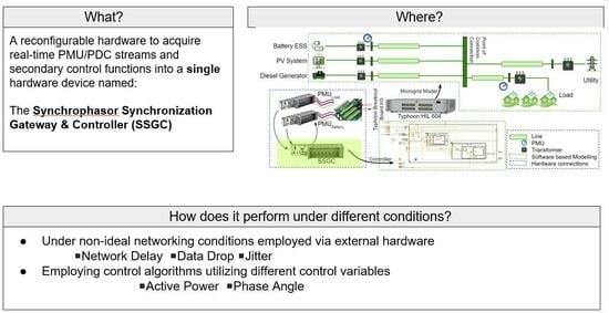
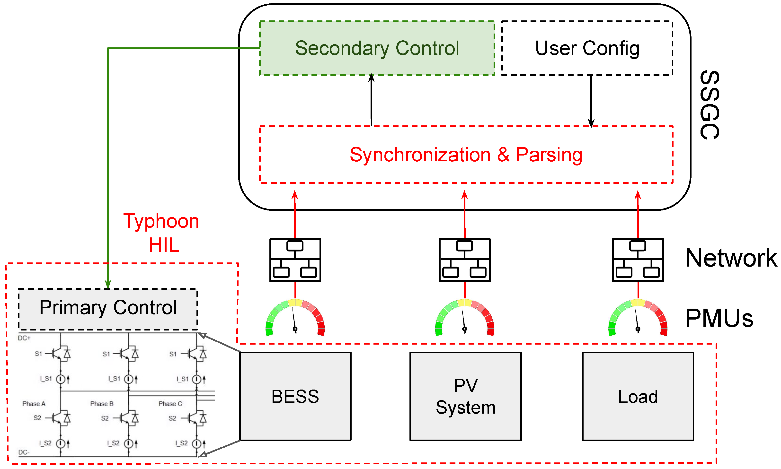
  • The capabilities of the Khorjin library are extended to develop a Synchrophasor Synchronization Gateway and Control (SSGC) architecture, consisting of a synchronization layer and a control layer.
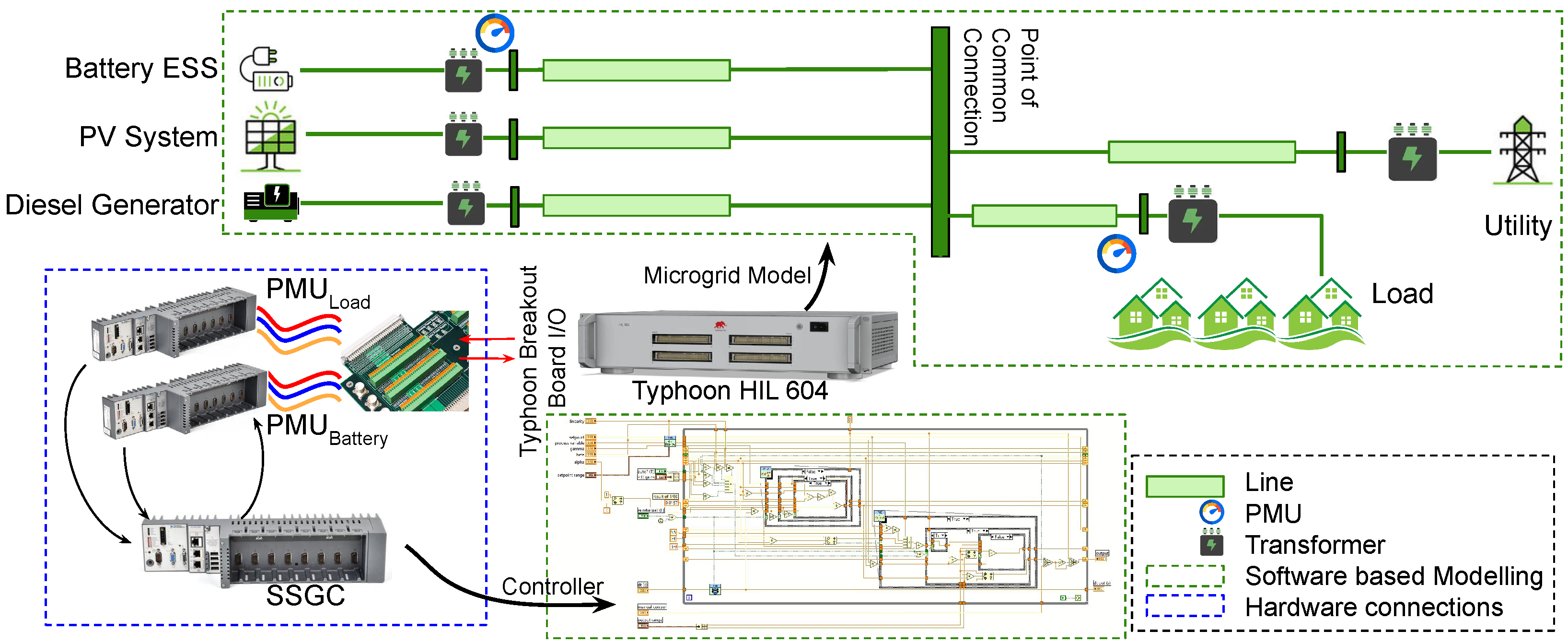
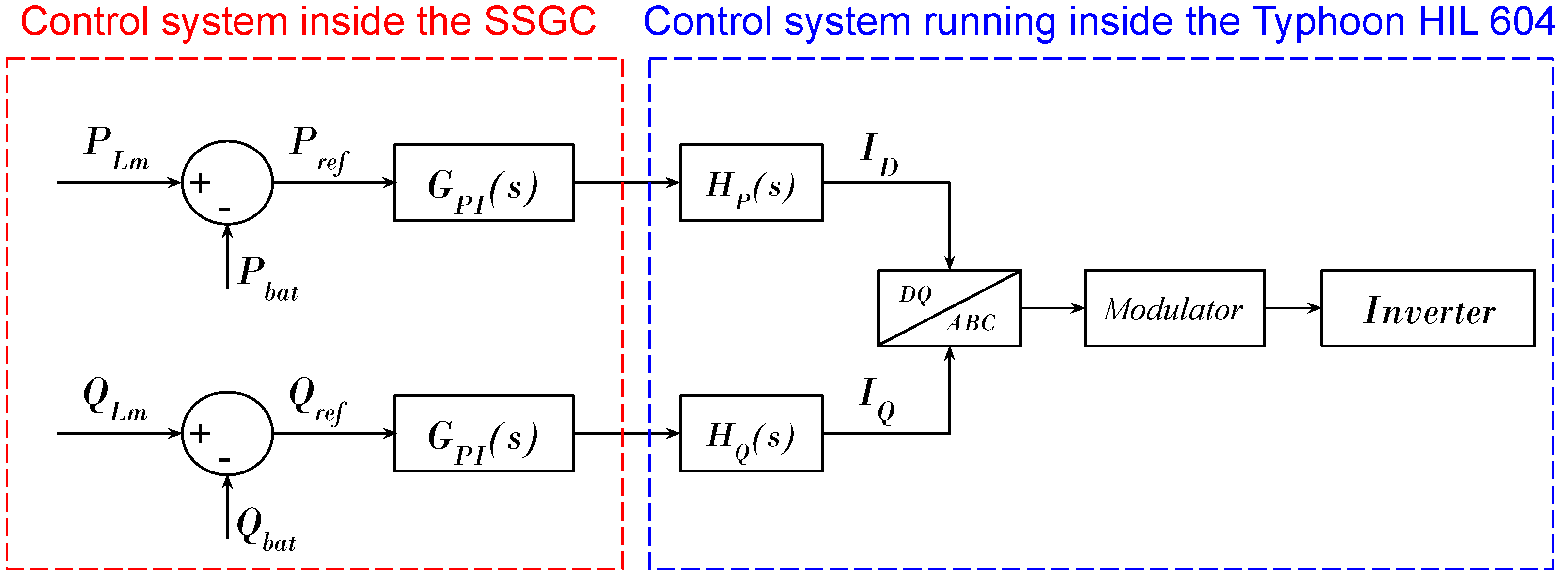
  • A new PMU-based approach for control of the DERs is introduced and demonstrated by using real-time Controller Hardware-In-the-Loop (CHIL) including a microgrid model. This approach exploits the proposed SSGC architecture.
  • The performance of the proposed SSGC architecture is analyzed under varying communication network conditions (including randomized configurations) with multiple PMU streams.
  • The proposed control system is further enhanced by applying Low Pass Filters (LPFs) in the real-time controller’s control error signal to mitigate the overswitching of the primary controllers inside a Battery Energy Storage System (BESS).
  • The real-time performance of the SSGC is demonstrated under the presence of faster transients in the system when the control signal is passed through the enhanced controller (with LPFs).
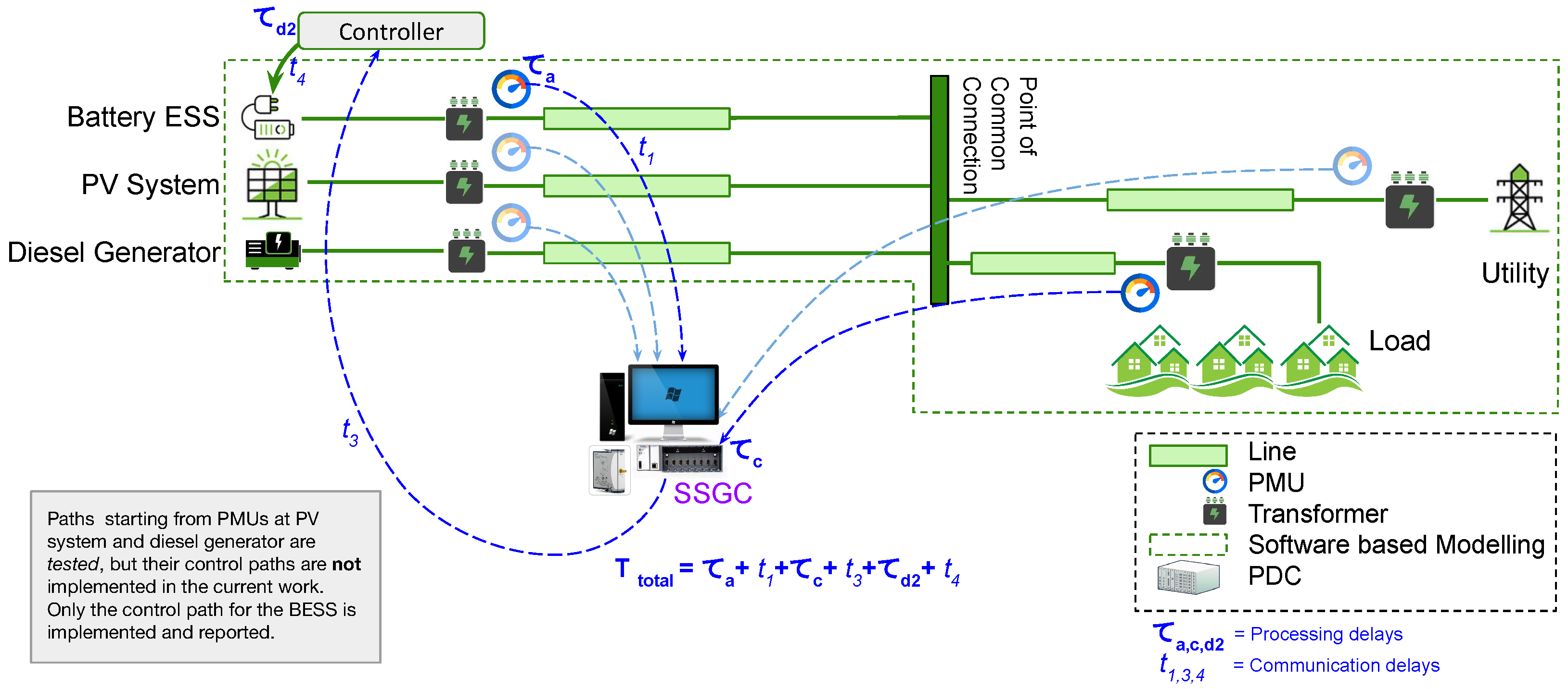
  • The SSGC architecture was validated by deploying a second type of secondary controller. The controller utilizes the phase-angle difference between two PMU locations to control the active power output.

1.4. Paper Organization

The remainder of this paper is organized as follows. Section 2 gives an overview of the real-time controller’s architecture and the experimental setup developed to validate the proposed approach in this paper. Section 3 presents the results of the performance of the SSGC under both ideal and impaired communication network conditions and the enhancement of the Battery Energy Storage System (BESS) response by enhancing the control function through LPFs, limiting unnecessary BESS switching. Finally, Section 4 outlines future work and Section 5 presents this paper’s major conclusions.

2. Architecture and Experimental Setup

2.1. Controller Architecture

The authors of [25] presented the Khorjin library, which receives, extracts and parses a C37.118.2 data stream before feeding the information to subscriber applications. The authors of [24,33] demonstrated the data unwrapping and time synchronization functionalities on the real-time embedded system (host), utilizing multiple instances of Khorjin extracting data from multiple incoming concurrent PMU streams in parallel.
In this paper, the ‘virtual instrument code’ running on the host side (in an RT OS) is extended and improved to incorporate crucial secondary control functionalities targeted to control DERs in a microgrid, whose one-line diagram and simplified view is shown in Figure 3. The real-time control system utilizes PI controllers that calculate their set point and process variables by unwrapping the current and voltage phasors received from the concurrent Khorjin instances. A simplified view of the system is demonstrated in Figure 4, which identifies both the electrical connections and communication interfaces of the setup. The detailed experimental setup is illustrated in Figure 5.
A Khorjin thread requires bidirectional data transmission capabilities for the communication link. After securing the TCP/IP connection, the SSG sends a ‘turn off transmission’ command and a ‘send CFG-2’ command. The PMU responds by sending the CFG-2 frame. At this point, the SSG has received all the required information from this frame to initiate the data transmission. Hence, the SSG now requests synchrophasor measurement data, and the PMU begins data transmission. This exact protocol is implemented in all the concurrent Khorjin instances. This process is graphically illustrated in Figure 6.
As can be observed in Figure 5 and Figure 7, the main goal of the real-time controller is to maintain the power at the Point of Common Connection (PCC) constant from the point of view of the utility, meaning that the microgrid self-balances by taking advantage of measurements at the PCC and other locations (e.g., at the BEES terminals). Because the goal of the controller is to redispatch the battery to meet load/generation changes within the microgrid, it is important to mitigate the BESS response in specific time scales. To achieve this goal, the real-time control system was enhanced by incorporating LPFs, as shown in Figure 8, which would prevent the controller from responding to possible high-frequency transients on the load side (e.g., switching transients).
The current work demonstrates a scenario where the proposed SSGC architecture is configured to regulate the power output from a Battery Energy Storage System (BESS)-based DER. As shown in Figure 8, the PI controller coded inside the SSGC hardware (situated at the remote location) determines the set point to be utilized at the local (primary) controller inside the BESS. The individual parameters for the PI controller were based on the specifications provided in the model illustrated in [34]. The PI controller was followed by a saturation block (with the upper and lower limits set at 1 and 1 , respectively) to ensure stability. The value of K p and K i were taken from the Typhoon specifications directly (for this particular application, K p = 0.5 and K i = 3.0). This control algorithm computes P and Q in real time from the voltage and current phasors it receives from the multiple incoming PMU streams. The controller uses P and Q as the control variable. It is also possible to utilize the voltage magnitude and phase-angle differences ( Δ δ ) as the control input variables [35,36,37,38]. The controller output is fed back to the real-time simulator’s analog input channels and used as a control input for the primary controller of the Li-Ion BESS, as shown in Figure 7. The proposed control architecture can take advantage of the hierarchical structure of the control system for microgrids, secondary control in particular, as summarized in [21].
It must be noted that, as shown in Figure 3 and Figure 5, the microgrid RT simulation model comprises a diesel generator, a PV system and an external grid alongside the BESS. All these energy resources work in synchronism to supply a configurable load. These models were based on the existing components available in the Typhoon HIL’s model library [34,39].

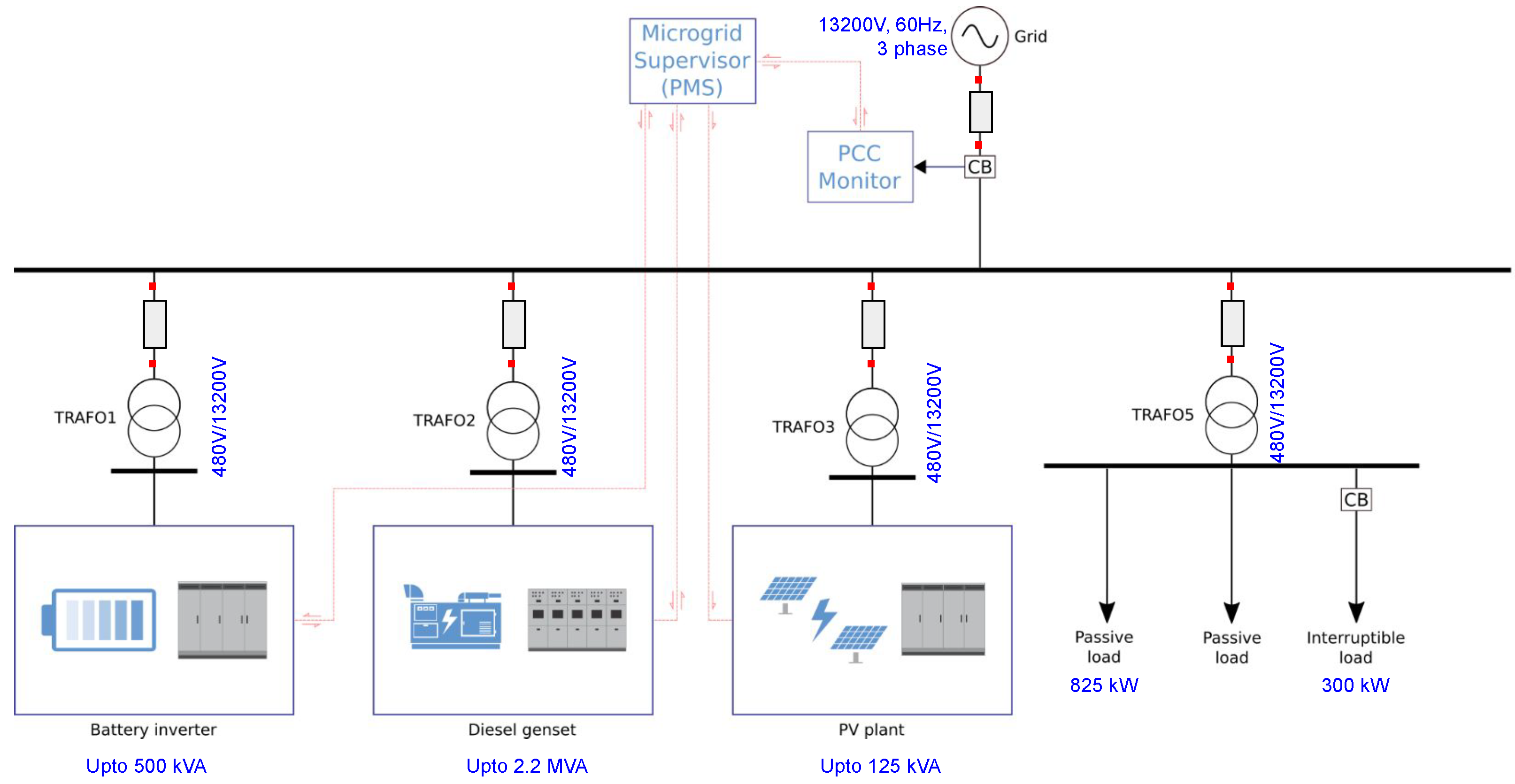
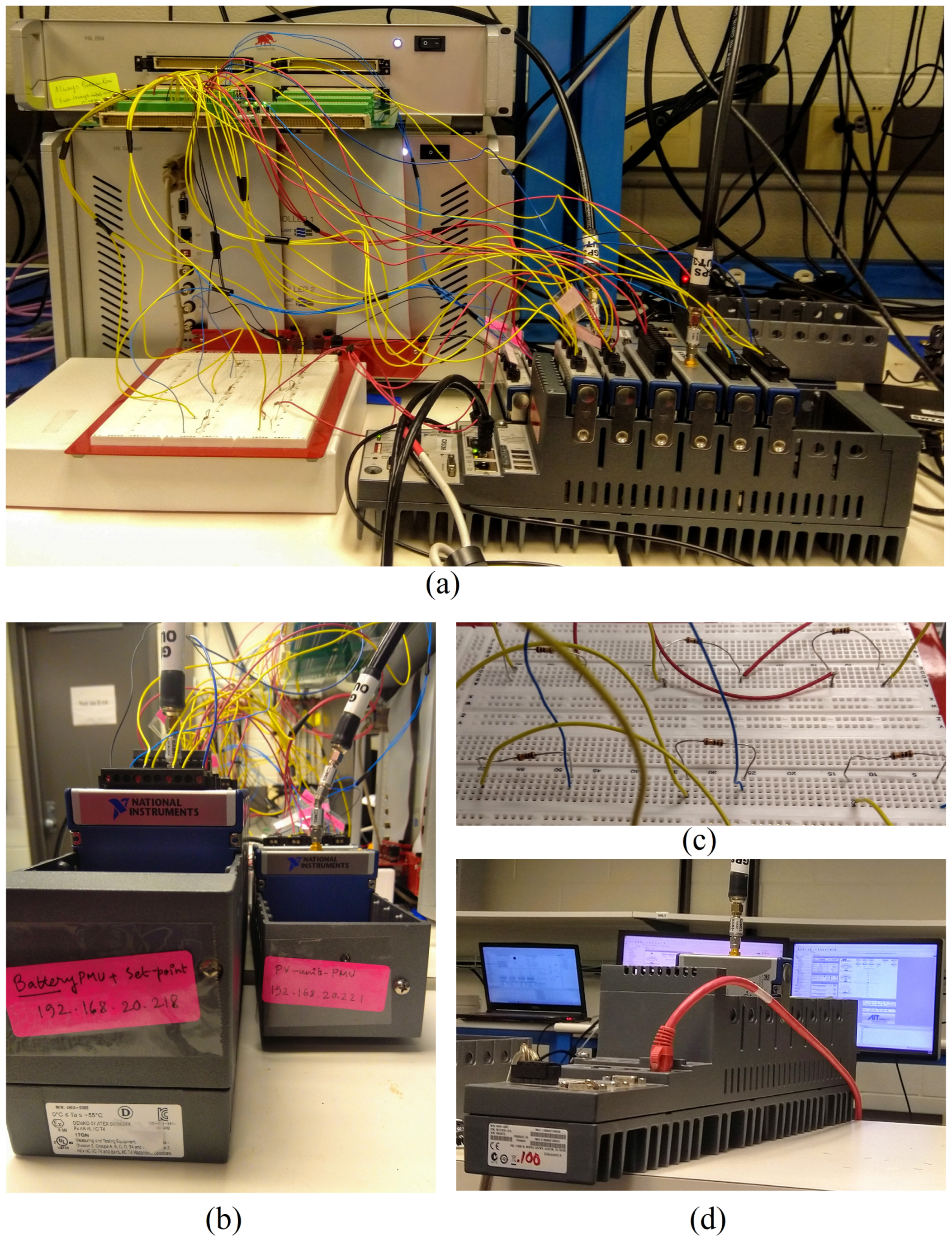
2.2. Experimental Setup

This paper reports a reconfigurable SSGC hardware that can suitably incorporate secondary and tertiary control functionalities. As proof of concept, the authors aim to demonstrate its functionalities through a real-time secondary controller to regulate the power output of the BESS implemented on the SSGC in this work. This is illustrated in the block diagram of Figure 8.

2.2.1. Scope of the Experiments Supported by the Experimental Setup

As shown in Figure 8, the proposed secondary control action utilizes a set point, which is computed in real time from the two parameters P L m , which represents the measurement from the load side, and P b a t , which represents the BESS output power. The experiments in this work will assume that the P P V (active power output from the PV system), P U t i (active power dispatch from the utility) and P D S G (active power output from the diesel generator) are constant. Under this condition, the parameter P r e f (reference power) will be a product of the changes in the total load consumption P l o a d only. For this part of the experiment, the two PMUs were placed near the load and near the BESS as the current measurements at these locations were expected to experience changes along with changes in the load and battery dispatch. As an extension, a further experiment was performed by taking the phase-angle difference ( δ P C C δ L o a d ) as the control variable to regulate the active power output from the BESS instead of using the active powers directly. For this part of the experiment, the phase angles were measured at the point of common coupling (PCC) and the load. Thus, the PMUs were placed accordingly. The reprogrammable and reconfigurable nature of the proposed SSGC hardware can be exploited to adapt the hardware to deploy different control schemes and control of different types of DERs. However, those experiments are considered to be beyond the scope of the current paper. For demonstration, only real-time synchrophasor-based P-Q control of the BESS is presented in this paper. Hence, this paper primarily focuses on the implementation of the SSGC architecture and its validation in the context of simple control-system development targeted for DERs. We also demonstrate how the control performance can be improved by implementing a Low Pass Filter (LPF) ( L P F ( s ) = 1 1 + τ S , where τ = 1 ω c ) to make the BESS operate safely under a condition where switching transients are present in the load.

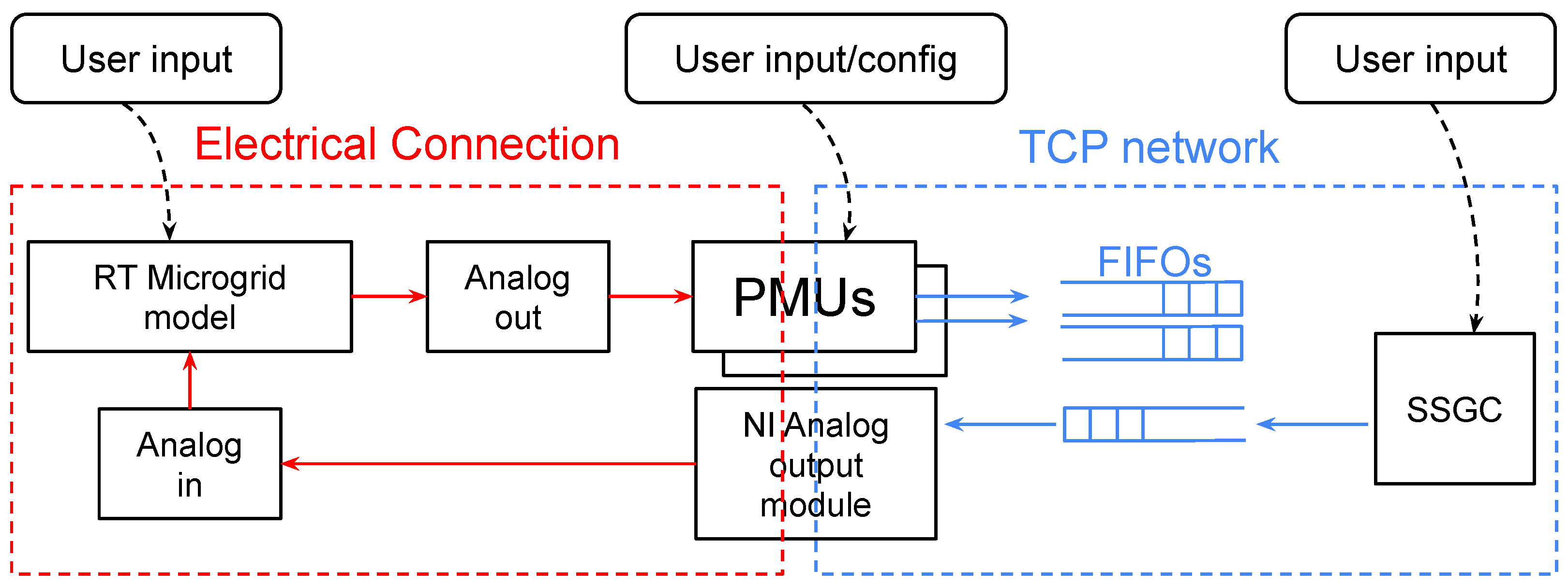
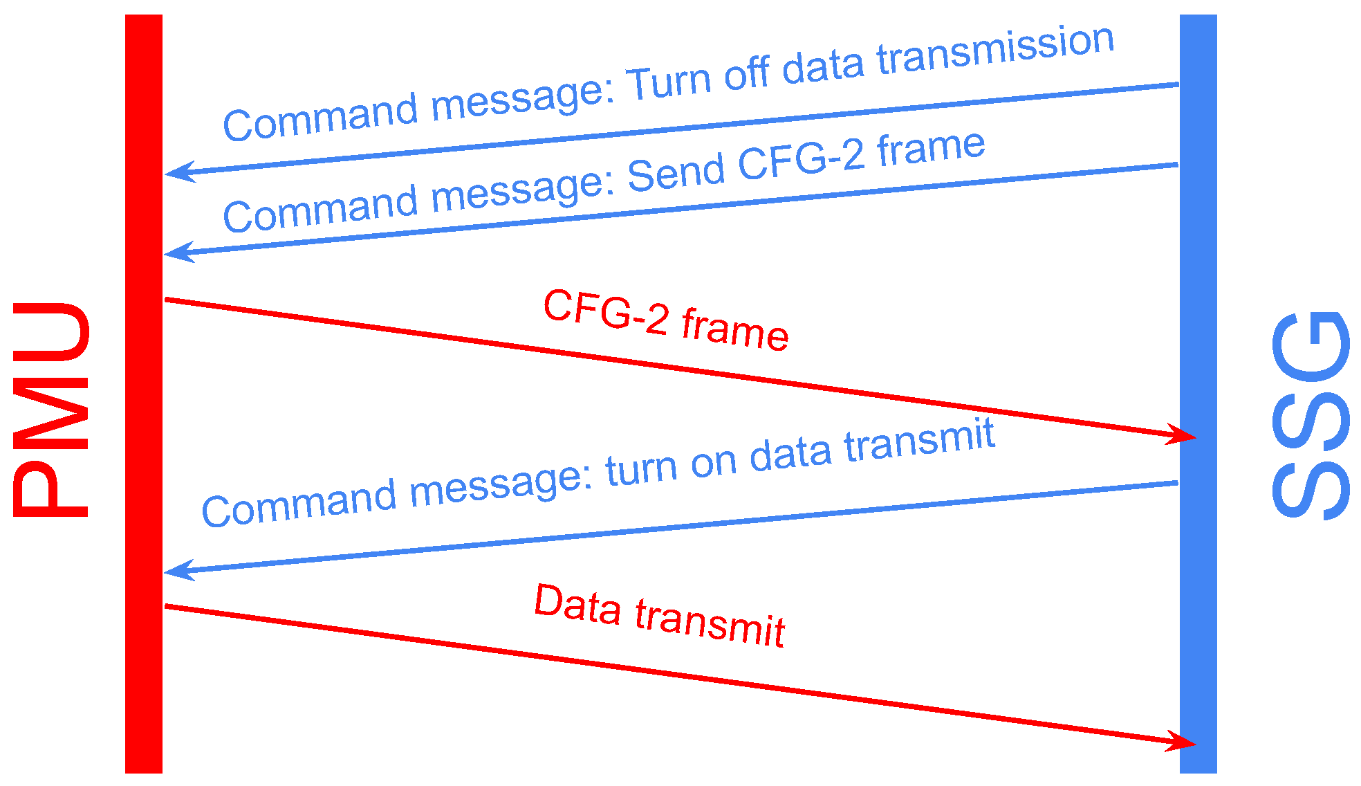
2.2.2. Real-Time Communications

It has been discussed that the SSGC requires real-time synchrophasor data (i.e., following the IEEE C37.118.2 std.) to be streamed at its input. Modern RT simulators have the capability to stream synchrophasor data directly from the RT model being simulated, without requiring external PMU hardware. However, the present work was completed by using Typhoon HIL control center’s 2020.4 release, where the IEEE C37.118 library was primitive and unstable (as discovered through experimentation) when connected to external hardware such as a PDC or SSGC (note that the 2022.4 and 2023.1 releases of the Typhoon HIL control center toolkit have stable and dedicated library components for streaming C37.118 data, and the authors of this paper chose not to adjust the hardware configuration and keep the PMUs as external hardware to facilitate impairment). This was chosen to facilitate tampering between the communications network between the PMUs and the SSGC hardware. With the introduction of external PMU hardware based on [40,41], it is simple to pick and choose individual PMUs and corrupt the communication network between any single PMU and the SSGC hardware.

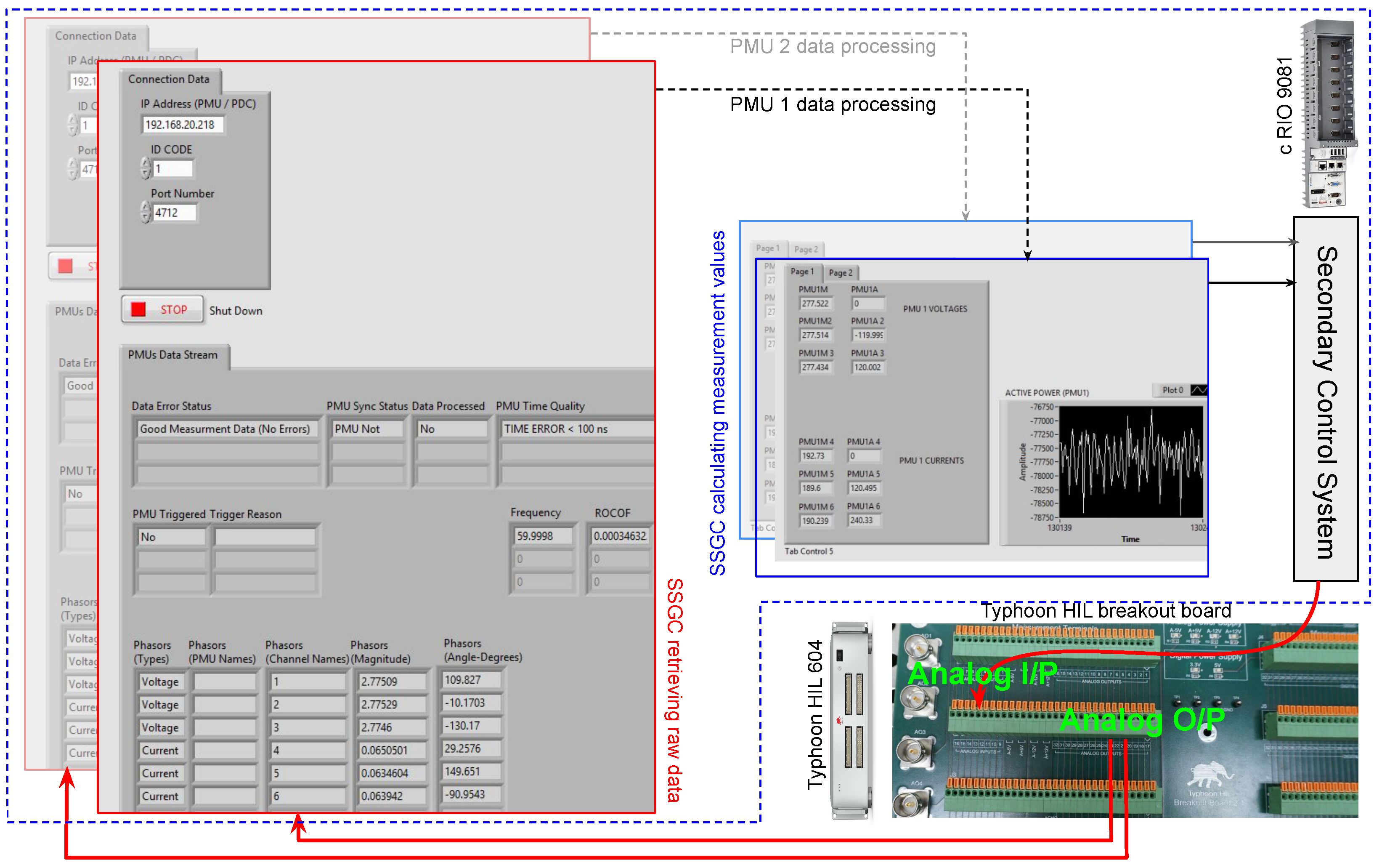
2.3. Hardware Integration

The aforementioned external PMUs (the hardware used is that reported in [42] and extended in [43]) were connected to the low-voltage analog outputs of the real-time simulator. It is crucial to note that these PMU designs feature both current and voltage inputs to function as PMUs whereas Typhoon HIL 604 hardware only provides analog voltage outputs. Thus, an external burden circuit was introduced in the experimental setup to perform the voltage-to-current conversion, as demonstrated in Figure 9c. The connection between Typhoon HIL 604 (the hosting microgrid model) and the PMUs (streaming synchrophasor data to SSGC) is shown in Figure 9a. Figure 9b demonstrates how the PMUs receive GPS signals to obtain precision timing, and Figure 9d shows the SSGC deployed in a remote location, communicating to the rest of the experimental setup through a standard Ethernet-based communication network.

SSGC Configuration and Integration in the Experimental Setup

Figure 10 shows how the LabVIEW GUI interacts with the physical inputs and outputs of the Typhoon HIL 604 and how the analog signal levels are scaled to obtain the measurements of actual voltages and currents. This technique enables the SSGC operation without any high external amplifiers that are typically required for HIL experiments [30], such as [44], making the experimental environment safer.
The communication network between the SSGC hardware and the PMUs was intentionally impaired during experimentation in order to test the robustness of the proposed control architecture. To perform these network impairments, the external Wide-Area Network emulator and impairment appliance hardware CandelaTech CT910 [45] was connected inside the network, which would tamper the communication link between PMUs and the SSGC. Using CT910, it is possible to introduce custom delays, data drops, jitters and bandwidth limitations within the network. The values of these parameters can be reprogrammed every second, and this procedure can be automated.

3. Results

3.1. SSGC Performance under Ideal Network Conditions

In this experiment, the total load is increased in a step by turning on the configurable load, as shown in Figure 3. Initially, a fixed load of 825 kW was supplied by the PV unit (125 kW), diesel generator (500 kW) and the utility (100 kW). This makes the initial dispatch for the BESS inverter to be fixed at 100 kW. With the system running in this “steady state”, a step increase of 300 kW in load was triggered externally.
Under this scenario, the control system must respond to this change in load. Hence, the BESS inverter and its dispatch increases from 100 kW to 400 kW. It is important to note that the portion of the controller (in Figure 8) within the dashed red box is implemented within the SSGC hardware. This portion is capable of utilizing synchrophasor measurement data obtained from the PMUs placed at the load and at the BESS. The PMU data are utilized to compute the active and reactive powers, which are then used to calculate a new set point (by using the PI controller block G P I ) to operate the BESS. This set point is then utilized by the internal control algorithm (implemented locally inside the BESS) to control the individual current and voltage output of the inverter inside the BESS. This portion of the control system was implemented locally within the BESS model of the real-time simulator because it generates high-frequency switching sequences for the individual semiconductor switches in the inverters that are modeled within the simulator.
Figure 11a shows the 300 kW manual load injection in the system. The SSGC incorporates a PI controller onboard. The output of this PI controller modulates the set point for the local BESS controller to operate, as shown in Figure 11b. This measurement is taken from the SSGC side. Meanwhile, in Figure 11c, the BESS power output response is shown. It can be observed from this figure that the power output of the battery increases from 100 kW to 400 kW to cover for the step increase in the load. Figure 11a–c demonstrate the SSGC’s performance under ideal conditions of the communication network while there are no external communication disturbances.

3.2. SSGC Performance under Nonideal Communication Network Conditions

Even though the SSGC hardware can be configured to control different DERs and employ sophisticated control algorithms, such demonstrations are considered to be beyond the scope of the current paper. For experimentation purposes, only the real-time synchrophasor-based control of the BESS is presented in this paper. Hence, the primary focus of this paper is the implementation of the SSGC architecture and its validation in the context of the P-Q control of the BESS-based DER.
Because this controller architecture relies on real-time synchrophasor communications, it is important to assess the performance of the proposed architecture under nonideal communication network conditions. Therefore, to test the robustness of the SSGC architecture, the communication network between the SSGC hardware and the PMUs was tampered with, as shown in Figure 12. As mentioned earlier, to perform experiments impairing the communications, an additional external hardware CandelaTech CT910 [45] was connected between the SSGC and the rest of the communication network system. This hardware enables the user to introduce custom delays and data drops within the network through a GUI or command line and is used for the experiments in the sequel.

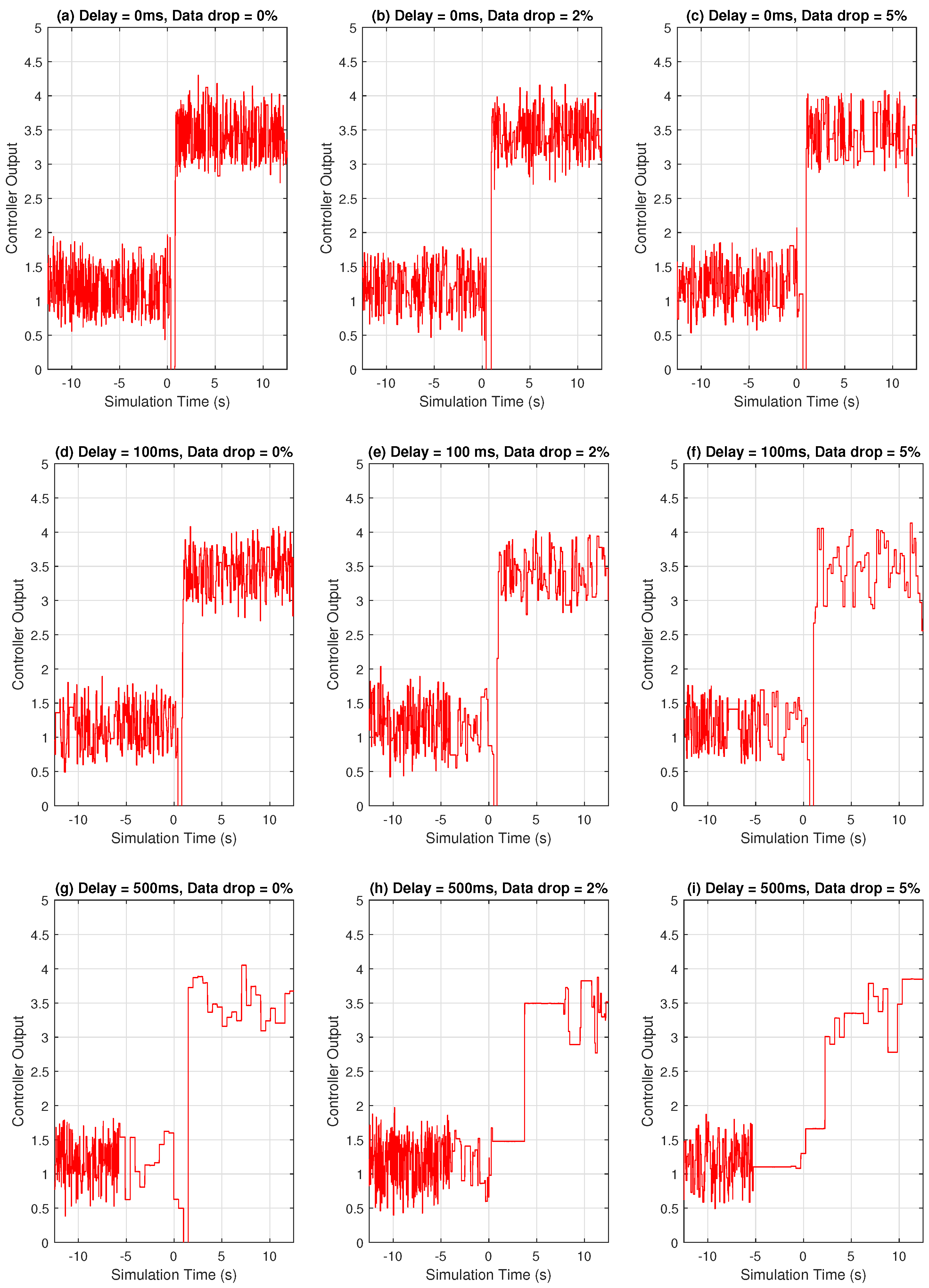
3.2.1. Network Tampering by Introducing Fixed Delay

In this particular experiment, artificial delays were introduced in between P M U 1 and the SSG prototype. To this end, a network-traffic generator within the CT910 was reconfigured to introduce artificial delays and thereby tamper with the network between the two ports where the P M U 1 and SSGC prototype were connected.
Figure 12 shows a representative connection where the CT910 device is utilized to tamper with the communication link between P M U 1 and the SSGC. The delays are introduced by CT910 (CT910 uses the LanForge 5.4.6 software library, which provides crucial command-line utilities and a stable GUI to interact with the communication link in real time). The delay between the time when a synchrophasor packet is generated and when that particular packet is received at the SSGC end can be computed by sharing the respective time stamps. This procedure is explained in detail by the authors of [24].
As a simple representative experiment, the network was impaired by injecting an additional 100 ms delay, and the network delay was computed in real time by time-stamp sharing. This network delay is plotted in Figure 13, which shows a window of 10 s, during which the communication link was tampered with an additional 100 ms delay.

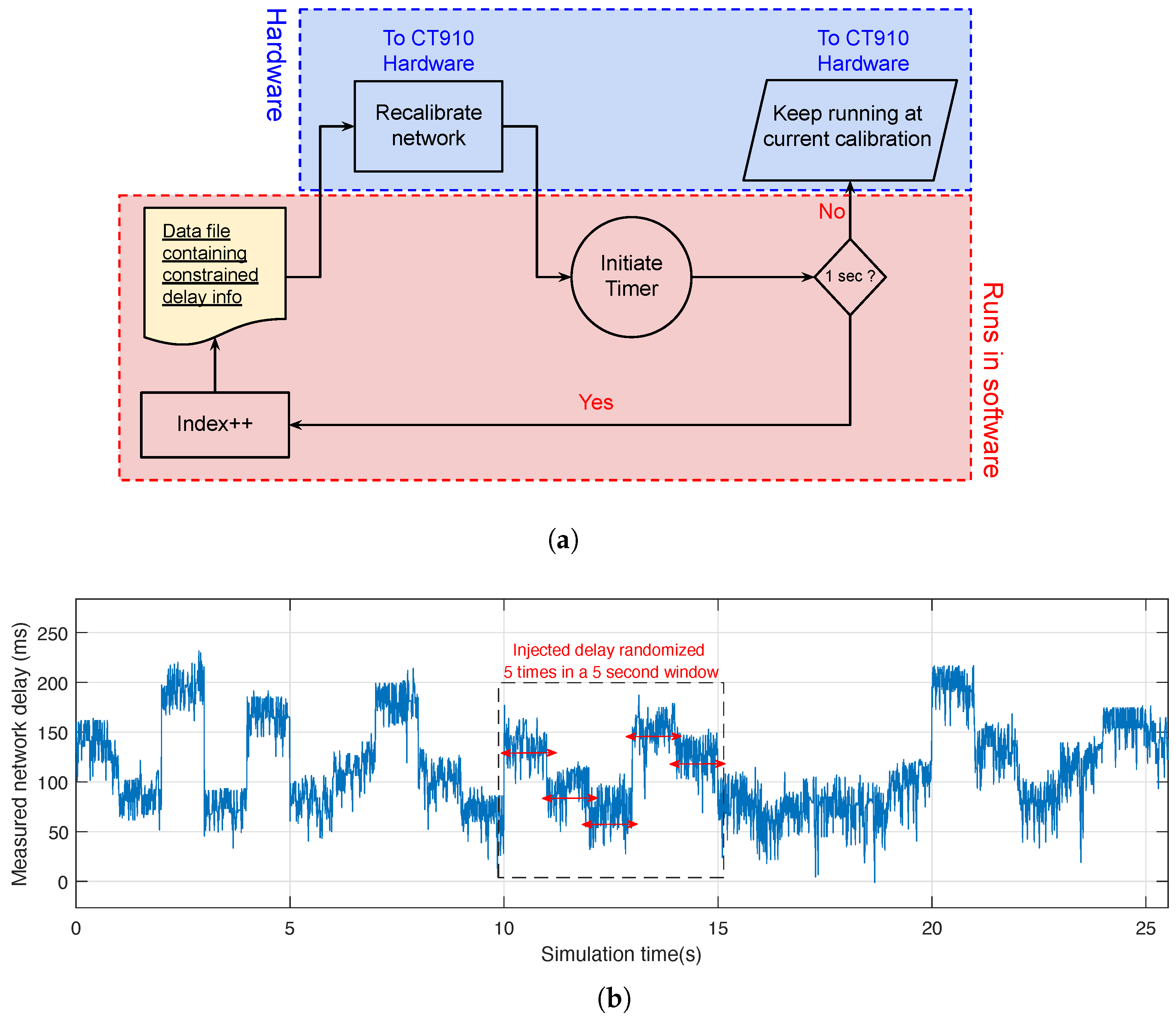
3.2.2. Network Tampering by Introducing Varying Delay

In this experiment, the communication link between the PMU and the SSGC is subjected to a network tampering that would randomize the injected delay every second. The hardware restricts the frequency of the network reconfiguration and dictates that, at most, the network can be reconfigured once every second. To achieve this, a custom script was executed on the CT910 hardware that would reconfigure its network interface with a random amount of delay every second. A pregenerated data file contained the amount of the injected delay in milliseconds and was used by the script to reconfigure the hardware with varying amounts of delay every second. The overall execution is shown in the flowchart of Figure 14a.
By following the same methodology to compute the network delay as described in Section 3.2.1, the network delay of this experiment is computed in real time. These results are shown in Figure 14b. It can be seen that the network reconfigures itself with a new value of the injected delay every second. The data file containing the raw values of the network delays was generated from a random variable following a uniform distribution between 0 and 200 ms.
Additionally, for the second part of this experiment, random delays were also generated to compute the network delay in real time by using a random variable following a normal distribution with a fixed mean and standard deviation (all the negative values generated were discarded because network delay cannot be negative). The experiment is carried out for 10 min (with the network reconfiguring the delay every 1 s) and repeated 10 times. If the network sustains itself (i.e., the controller keeps operating after 10 min of real-time simulation), the experiment run is termed as successful.
This batch of trials (10 runs, each for a duration of 10 min) was performed with different values of the mean and standard deviation of the injected delay, and whether or not the 10 individual runs were successful is summarized in Table 2. The mean delay was varied from 50 ms to 750 ms, and the standard deviation was varied from 5 ms to 200 ms. It can be seen that the performance progressively deteriorates at higher values of the mean delay. It can also be seen that when the mean delay is 500 ms, a small increase in the standard deviation leads to a significant number of unsuccessful trials. It is interesting to note that the unsuccessful runs failed because the First-In First-Out (FIFO) instances, which transmit data from the PMUs to the SSGC, gradually filled up as the PMUs keep streaming data into a slow network. This shows that in real-time applications under nonideal communication interfaces, the adequate sizing of elastic storage elements in the embedded systems is crucial for the control architecture to function.

3.2.3. Effect of Data Drop in the Communication Network

In this experiment, the quality of a controller’s output signal is analyzed for varying network delays and varying data-drop rates injected simultaneously in the communication network. The controller regulates the power output of the inverter inside the BESS, as demonstrated in Section 3.1. However, its performance is expected to deteriorate under stressed communication network conditions (i.e., higher delay and higher data-drop rates). The results of these tests are summarized in Figure 15. It can be observed that the analog output of the remote controller loses the control signal resolution under higher network delays and higher data-drop rates. However, as discussed earlier in Section 3.1, the control objective of the SSGC does not involve any management of fast system dynamics. Thus, in the short term (up to 30 s), the SSGC-driven control architecture can sustain itself even while operating within a tampered network under drastic delay and data-drop conditions.
An additional set of trials were conducted for this experiment. In these trials, the SSGC was set to operate freely under tampered network conditions, and experiments were run to test whether or not it can sustain itself for longer periods of time. The network was tampered with by introducing network delays and data drop. Under these conditions, the network was kept running for 10 min. After 10 min, it was determined if the SSGC was still receiving all the PMU streams successfully and if the real-time simulator was still receiving the controller’s output. Observations were taken 10 times for each communication network condition. The summary of these results is shown in Table 3. As can be observed, the network delay and data drop can both adversely effect the robustness of the SSGC. In fact, in a situation where the SSGC is subjected to both a high network delay coupled with a high data-drop rate, the SSGC is almost certain to be unable to sustain itself for a long period of time. However, for lower delays and lower data-drop rates, the SSGC is proven to be reliable. For instance, consider the case for a 0.5% data drop and 50 ms delay: 10 out of 10 runs were sustained, while for a 5% data drop and 200 ms delay, only 2 out 10 runs were sustained.

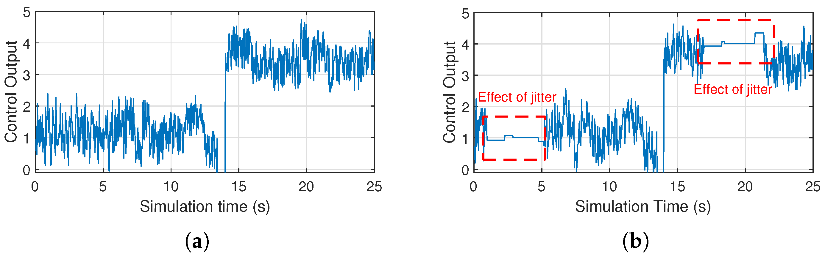
3.2.4. Effect of Jitter on the Communication Network

Jitter is defined as the variation in the time delay between when a signal is transmitted and when it is received over a network connection. The CT910 hardware has the provision of incorporating two parameters: jitter amount and jitter frequency in the network configuration. The parameter jitter amount defines the maximum amount of delay mismatch introduced in the network, and the jitter frequency determines what percent of data packets would experience the jitter. For this experiment, a jitter frequency of 10% and a maximum jitter delay of 500 ms was introduced in the network. This test was repeated with and without the jitter present. Figure 16 shows the effect of jitter on the control signal being transmitted by SSGC. The jitter delay was maxed at 500 ms, which meant that only a few packets would be experiencing a jitter delay around that range. Experimentally, it was observed that the effect of jitter is visible intermittently for some brief windows (denoted by red boxes in Figure 16), during which the control signal slows down its update rate significantly (thus dropping the high-frequency components). However, these windows are short and are only observed while the applied jitter delay is close to its maximum permissible limit of 500 ms.

3.3. Control Performance Enhancement through LPF Functions

It needs to be noted that only one scenario for controlling the DERs within a microgrid is demonstrated in this paper. In that scenario, the battery is covering for a step increase in the load. While this experiment is an important ‘proof of concept’, additional experimentation is crucial before implementing the proposed architecture to control real-world DERs.
In real-world applications, the behavior of a BESS-based DER in a power system is more complex than what simulation models can capture, and more importantly, the operation of the controllers are restricted by the physics of the battery. In fact, the batteries utilized in energy storage systems are limited by their response times, which are different during charging and discharging operations in addition to their power availability. The authors of [46] reported that the average response time for a Battery Energy Storage System during charging is about 2.2 s and during discharging is about 0.6 s. Keeping these numbers in mind, the battery cannot be subjected to faster changes than those allowed by the charge and discharge rates. Hence, when aiming to control power flows to balance load/generation changes, any frequency variations, if kept unfiltered, would rapidly increase the switching and would generate excessive heat, thus compromising the health of the batteries.
To address this issue, a practical approach is adopted to restrict the response bandwidth of the proposed controller. To this end, a low-pass filter was introduced as an SSG function, with the goal to eliminate the high-frequency variations in the control signal. In addition, it may also slow down the response of the overall control response. Hence, the LPF needs to be adequately tuned. To illustrate, experiments are conducted by varying the cut-off frequency of this LPF from 4 Hz to 0.25 Hz. The control responses of each of these cases are demonstrated in Figure 17. It can be seen from the results that at a lower cut-off frequency (≤0.5 Hz), the control system is free of high-frequency components, and the control signal can be safely employed in the BESS without exposing the BESS to overswitching. These filters can reliably bring the response of the SSGC-based control system within the permissible limit for battery operations, as reported in [46].

3.4. Control System Redesign to Utilize Phase-Angle Measurements

As a ‘proof of concept’ that the SSGC can support different control functions, in this section, the control system is redesigned to utilize the phase-angle difference as the controller input, and the power flow is regulated the same way as before. The usage of the phase angle to control the power flow is a tried and tested technique which has been proposed, theorized and archived in [47,48,49]. Synchrophasor technology is capable of reporting accurate phase-angle measurements in real time [35,36,37,38]. This makes this technology suitable for phase-angle-based power-flow control. In this paper, the phase-angle difference between the load and the point of common coupling is used as the control variable to direct the power flow from the BESS. It is to be noted that, for distribution systems, the angle difference between the buses can be very small. Hence, the controller needs to be tuned with precision. Thus, even though the control system architecture is independent of the control variable (the active power or phase angle), the internal PI controller requires significant retuning.
Experiments were performed with the BESS power output being controlled by the phase-angle difference δ P C C δ l o a d . The results of this experiment are summarized in Figure 18a–c. It can be observed from Figure 18c that the active power output increases from ≃100 kW to ≃400 kW. This response is consistent with the results demonstrated previously in Figure 11c.

4. Future Works

The current paper introduces a new architecture for control system implementation for DERs in microgrids by utilizing synchrophasor measurements. As a ‘proof of concept’, one specific case study was tested where the BESS output is increased to match the step increase in the load. Different cases featuring the control of a full range of DERs and a full range of behaviors on the load side, microgrid conditions, etc., must be performed in order to demonstrate the resilience and robustness of the proposed architecture. This work is outside the scope of this paper and is left as future work.
For BESSs, the state of charge (SOC) of the battery is a crucial parameter. In all realistic BESS control systems, based on the SOC, the battery is often put into either charging or discharging mode. The current paper assumes the SOC to be high enough so that the battery can reliably operate in discharging mode; i.e., it can feed active loads. For real systems, this will not be the case. To address this, an additional control loop must be designed to utilize the SOC of the battery and ensure the safe and reliable operation of the BESS. This requires coordination and information exchange with Battery Management Systems (BMSs) and will be the subject of future research.

5. Conclusions

The proposed Synchrophasor Synchronization Gateway and Control system can reduce the complexity and latency of the synchrophasor system and communication network when compared to traditional WAMS/WAMPAC systems by exploiting and expanding upon the existing Khorjin library. This architecture was utilized successfully to implement a networked control system for a real-time microgrid model.
A scenario for controlling the DERs within the microgrid was used for experimentation in this paper. In that scenario, the BESS is capable of using synchrophasor data from different locations to respond to a step increase in the load. It was also demonstrated that this architecture can be successful irrespective of the actual control algorithm being employed within it.
Experimentally, the SSGC architecture was tested under different network conditions to establish its validity and robustness. More specifically, the network was subjected to delay, jitter and data drops through external hardware. The performance of the controller was evaluated under those different network conditions. It was observed that for lower values of the data-drop rate (≤2%) and lower values of the network delay (≤100 ms), the SSGC-based control system is reliable. It was also observed that the introduction of jitter makes the controller lose a significant amount of high-frequency components. However, up to a maximum jitter occurrence of 10% and maximum jitter delay of 500 ms, the SSGC sustains itself successfully even for longer runs.
Finally, an LPF was designed to prevent the BESS from overswitching. This filter would ensure that the battery operations are within the physical limits of the battery and thus increase the lifetime of the battery units within the BESS.
The main limitation of the implementation presented in this work is the cost associated with the National Instruments’ cRIO hardware. While such hardware was ideal for prototyping and testing, it is cost prohibitive for product development. For the real-world deployment of the proposed architecture, it would be crucial to utilize a low-cost hardware platform to make it economically viable. Consequently, migrating the Khorjin dynamically linked library (DLL) to a different platform is the first step towards the authors’ future work.

Author Contributions

Conceptualization, P.M.A., L.V. and K.K.; Methodology, P.M.A., L.V. and K.K.; Software, P.M.A. and H.C.; Validation, P.M.A.; Investigation, P.M.A., L.V., H.C. and K.K.; Resources, L.V.; Writing—original draft, P.M.A.; Writing—review & editing, L.V.; Supervision, L.V. and K.K.; Project administration, L.V.; Funding acquisition, L.V. All authors have read and agreed to the published version of the manuscript.

Funding

This research was funded in part by the New York State Energy Research and Development Authority (NYSERDA) under agreement number 137948.

Data Availability Statement

The The data presented in this study are available on request from the corresponding author.

Conflicts of Interest

The funders had no role in the design of the study; in the collection, analyses, or interpretation of data; in the writing of the manuscript; or in the decision to publish the results.

Abbreviations

BESSBattery Energy Storage System
DERDistributed Energy Resources
HILHardware-In-the-Loop
CHILController Hardware-In-the-Loop
LPFLow Pass Filter
PCCPoint of common coupling
PMUPhasor Measurement Unit
PDCPhasor Data Concentrator
PVPhotovoltaic
SSGSynchrophasor Synchronization Gateway
SSGCSynchrophasor Synchronization Gateway and Controller
WACSWide-area control system
WAMPACWide-Area Monitoring Protection and Control System

References

  1. IEEE Std C37.118.2-2011; IEEE Standard for Synchrophasor Data Transfer for Power Systems. Revision of IEEE Std C37.118-2005. IEEE: New York, NY, USA, 2011; pp. 1–53. [CrossRef]
  2. Available online: https://www.gegridsolutions.com/multilin/catalog/p30.htm (accessed on 25 September 2023).
  3. Available online: https://selinc.com/products/3573/ (accessed on 25 September 2023).
  4. Available online: https://nrec.com/en/index.php/product/productInfo/571.html (accessed on 25 September 2023).
  5. Castello, P.; Muscas, C.; Pegoraro, P.A.; Sulis, S. Low-cost implementation of an active phasor data concentrator for smart grid. In Proceedings of the 2018 Workshop on Metrology for Industry 4.0 and IoT, Brescia, Italy, 16–18 April 2018; pp. 78–82. [Google Scholar] [CrossRef]
  6. Adamiak, M.G.; Kanabar, M.; Rodriquez, J.; Zadeh, M.D. Design and implementation of a synchrophasor data concentrator. In Proceedings of the 2011 IEEE PES Conference on Innovative Smart Grid Technologies—Middle East, Jeddah, Saudi Arabia, 17–20 December 2011; pp. 1–5. [Google Scholar] [CrossRef]
  7. Retty, H.; Delport, J.; Centeno, V. Development of tests and procedures for evaluating phasor data concentrators. In Proceedings of the 2013 IEEE Grenoble Conference, Grenoble, France, 16–20 June 2013; pp. 1–5. [Google Scholar] [CrossRef]
  8. Vanfretti, L.; Jónsdóttir, G.M.; Almas, M.S.; Rebello, E.; Firouzi, S.R.; Baudette, M. Audur—A platform for synchrophasor-based power system wide-area control system implementation. SoftwareX 2018, 7, 294–301. [Google Scholar] [CrossRef]
  9. Danielson, C.F.M.; Vanfretti, L.; Almas, M.S.; Choompoobutrgool, Y.; Gjerde, J.O. Analysis of communication network challenges for synchrophasor-based wide-area applications. In Proceedings of the 2013 IREP Symposium Bulk Power System Dynamics and Control—IX Optimization, Security and Control of the Emerging Power Grid, Rethymno, Greece, 25–30 August 2013; pp. 1–13. [Google Scholar] [CrossRef]
  10. Yao, W.; You, S.; Wang, W.; Deng, X.; Li, Y.; Zhan, L.; Liu, Y. A Fast Load Control System Based on Mobile Distribution-Level Phasor Measurement Unit. IEEE Trans. Smart Grid 2020, 11, 895–904. [Google Scholar] [CrossRef]
  11. Liu, Y.; You, S.; Yao, W.; Cui, Y.; Wu, L.; Zhou, D.; Zhao, J.; Liu, H.; Liu, Y. A Distribution Level Wide Area Monitoring System for the Electric Power Grid–FNET/GridEye. IEEE Access 2017, 5, 2329–2338. [Google Scholar] [CrossRef]
  12. You, S.; Zhao, J.; Yao, W.; Liu, Y.; Cui, Y.; Wu, L.; Guo, J.; Liu, Y. FNET/GridEye for Future High Renewable Power Grids—Applications Overview. In Proceedings of the 2018 IEEE PES Transmission & Distribution Conference and Exhibition—Latin America (T & D-LA), Lima, Peru, 18–21 September 2018; pp. 1–5. [Google Scholar] [CrossRef]
  13. Liu, Y.; Yao, W.; Zhou, D.; Wu, L.; You, S.; Liu, H.; Zhan, L.; Zhao, J.; Lu, H.; Gao, W.; et al. Recent developments of FNET/GridEye—A situational awareness tool for smart grid. CSEE J. Power Energy Syst. 2016, 2, 19–27. [Google Scholar] [CrossRef]
  14. Schweitzer, E.O.; Whitehead, D.; Zweigle, G.; Ravikumar, K.G. Synchrophasor-based power system protection and control applications. In Proceedings of the 2010 63rd Annual Conference for Protective Relay Engineers, College Station, TX, USA, 29 March–1 April 2010; pp. 1–10. [Google Scholar]
  15. Rodrigues, Y.R.; Abdelaziz, M.; Wang, L. D-PMU Based Secondary Frequency Control for Islanded Microgrids. IEEE Trans. Smart Grid 2020, 11, 857–872. [Google Scholar] [CrossRef]
  16. Zenelis, I.; Wang, X.; Kamwa, I. Online PMU-Based Wide-Area Damping Control for Multiple Inter-Area Modes. IEEE Trans. Smart Grid 2020, 11, 5451–5461. [Google Scholar] [CrossRef]
  17. Chenine, M.; Nordström, L. Investigation of communication delays and data incompleteness in multi-PMU Wide Area Monitoring and Control Systems. In Proceedings of the 2009 International Conference on Electric Power and Energy Conversion Systems, (EPECS), Sharjah, United Arab Emirates, 10–12 November 2009; pp. 1–6. [Google Scholar]
  18. Microgrid Knowledge. Available online: https://microgridknowledge.com/microgrids-navigant/ (accessed on 25 September 2023).
  19. Lasseter, R.H. MicroGrids. In Proceedings of the 2001 IEEE Power Engineering Society Winter Meeting, Conference Proceedings (Cat. No.01CH37194), Columbus, OH, USA, 28 January–1 February 2001; Volume 1, pp. 146–149. [Google Scholar] [CrossRef]
  20. Hatziargyriou, N.; Asano, H.; Iravani, R.; Marnay, C. Microgrids. IEEE Power Energy Mag. 2007, 5, 78–94. [Google Scholar] [CrossRef]
  21. Bidram, A.; Davoudi, A. Hierarchical Structure of Microgrids Control System. IEEE Trans. Smart Grid 2012, 3, 1963–1976. [Google Scholar] [CrossRef]
  22. Canciello, G.; Cavallo, A.; Guida, B. Control of Energy Storage Systems for Aeronautic Applications. J. Control Sci. Eng. 2017, 2017, 2458590. [Google Scholar] [CrossRef]
  23. Cavallo, A.; Canciello, G.; Guida, B. Energy Storage System Control for Energy Management in Advanced Aeronautic Applications. Math. Probl. Eng. 2017, 2017, 4083132. [Google Scholar] [CrossRef]
  24. Adhikari, P.M.; Vanfretti, L. Delay Analysis of a Real-Time Hard Reconfigurable Synchrophasor Synchronization Gateway. In Proceedings of the International Conference on Control and Optimization of Renewable Energy Systems (CORES), Anaheim, CA, USA, 6–7 December 2019; Available online: https://www.actapress.com/PaperInfo.aspx?paperId=456528 (accessed on 25 September 2023).
  25. Firouzi, S.R.; Vanfretti, L.; Ruiz-Alvarez, A.; Hooshyar, H.; Mahmood, F. Interpreting and implementing IEC 61850-90-5 Routed-Sampled Value and Routed-GOOSE protocols for IEEE C37.118.2 compliant wide-area synchrophasor data transfer. Electr. Power Syst. Res. 2017, 144, 255–267. [Google Scholar] [CrossRef]
  26. Buttayak, S.; Wornpuen, A.; Promparn, N.; Charbkaew, N.; Bunyagul, T. Design of Phasor Data Concentrator for phasor monitoring system. In Proceedings of the 2012 IEEE Conference on Sustainable Utilization and Development in Engineering and Technology (STUDENT), Kuala Lumpur, Malaysia, 6–9 October 2012; pp. 102–107. [Google Scholar] [CrossRef]
  27. Bihari, S.P.; Sadhu, P.K.; Sarita, K.; Khan, B.; Arya, L.D.; Saket, R.K.; Kothari, D.P. A Comprehensive Review of Microgrid Control Mechanism and Impact Assessment for Hybrid Renewable Energy Integration. IEEE Access 2021, 9, 88942–88958. [Google Scholar] [CrossRef]
  28. Guerrero, J.M.; Vasquez, J.C.; Matas, J.; de Vicuna, L.G.; Castilla, M. Hierarchical Control of Droop-Controlled AC and DC Microgrids—A General Approach Toward Standardization. IEEE Trans. Ind. Electron. 2011, 58, 158–172. [Google Scholar] [CrossRef]
  29. Pourramezan, R.; Seyedi, Y.; Karimi, H.; Zhu, G.; Mont-Briant, M. Design of an advanced phasor data concentrator for monitoring of distributed energy resources in smart microgrids. IEEE Trans. Ind. Inform. 2017, 13, 3027–3036. [Google Scholar] [CrossRef]
  30. Guillaud, X.; Faruque, M.O.; Teninge, A.; Hariri, A.H.; Vanfretti, L.; Paolone, M.; Dinavahi, V.; Mitra, P.; Lauss, G.; Dufour, C.; et al. Applications of Real-Time Simulation Technologies in Power and Energy Systems. IEEE Power Energy Technol. Syst. J. 2015, 2, 103–115. [Google Scholar] [CrossRef]
  31. Konakalla, S.A.R.; Valibeygi, A.; de Callafon, R.A. Microgrid dynamic modeling and islanding control with synchrophasor data. IEEE Trans. Smart Grid 2020, 11, 905–915. [Google Scholar] [CrossRef]
  32. Castello, P.; Muscas, C.; Pegoraro, P.A.; Sulis, S. Active phasor data concentrator performing adaptive management of latency. Sustain. Energy Grids Netw. 2018, 16, 270–277. [Google Scholar] [CrossRef]
  33. Adhikari, P.M.; Vanfretti, L.; Mishra, C.; Jones, K.D. A Reconfigurable Synchrophasor Synchronization Gateway & Controller Architecture for DERs. In Proceedings of the 2022 International Conference on Smart Grid Synchronized Measurements and Analytics (SGSMA), Split, Croatia, 24–26 May 2022; pp. 1–6. [Google Scholar] [CrossRef]
  34. Microgrids. Available online: https://bit.ly/TyphoonHILMG (accessed on 25 September 2023).
  35. Almas, M.S.; Baudette, M.; Vanfretti, L. Utilizing synchrophasor-based supplementary damping control signals in conventional generator excitation systems. Electr. Power Syst. Res. 2018, 157, 157–167. [Google Scholar] [CrossRef]
  36. Díez-Maroto, L.; Vanfretti, L.; Almas, M.S.; Jónsdóttir, G.M.; Rouco, L. A WACS exploiting generator Excitation Boosters for power system transient stability enhancement. Electr. Power Syst. Res. 2017, 148, 245–253. [Google Scholar] [CrossRef]
  37. Rebello, E.; Vanfretti, L.; Almas, M.S. Experimental Testing of a Real-Time Implementation of a PMU-Based Wide-Area Damping Control System. IEEE Access 2020, 8, 25800–25810. [Google Scholar] [CrossRef]
  38. Chompoobutrgool, Y.; Vanfretti, L. Using PMU signals from dominant paths in power system wide-area damping control. Sustain. Energy Grids Netw. 2015, 4, 16–28. [Google Scholar] [CrossRef]
  39. Plug-and-Play Microgrid Library and Testing of Microgrid Controller. Available online: https://bit.ly/TyphoonControl (accessed on 25 September 2023).
  40. NI Expertise: Power Quality Analysis. Available online: https://bit.ly/NIPQAnalysis (accessed on 25 September 2023).
  41. Derviškadić, A.; Romano, P.; Pignati, M.; Paolone, M. Architecture and experimental validation of a low-latency phasor data concentrator. IEEE Trans. Smart Grid 2018, 9, 2885–2893. [Google Scholar] [CrossRef]
  42. LabVIEW Electrical Power Toolkit API Reference. Available online: https://bit.ly/NIPMUvis (accessed on 25 September 2023).
  43. Adhikari, P.M.; Hooshyar, H.; Vanfretti, L. Experimental Quantification of Hardware Requirements for FPGA-Based Reconfigurable PMUs. IEEE Access 2019, 7, 57527–57538. [Google Scholar] [CrossRef]
  44. Available online: https://www.typhoon-hil.com/products/hil-connect/ (accessed on 25 September 2023).
  45. CT 910. Available online: https://www.candelatech.com/ct910_product.php (accessed on 25 September 2023).
  46. Song, L.; Wang, Z.; Luo, W. Analysis on the Response Time of the Battery Energy Storage System. Mater. Sci. Energy Eng. (CMSEE 2014) 2015, 553–560. [Google Scholar] [CrossRef]
  47. Edris, A.; Mehraban, A.S.; Rahman, M.; Gyugyi, L.; Arabi, S.; Reitman, T. Controlling the flow of real and reactive power. IEEE Comput. Appl. Power 1998, 11, 20–25. [Google Scholar] [CrossRef]
  48. Pierce, R.E.; Hamilton, B.W. Phase-angle control of system interconnections. Electr. Eng. 1939, 58, 83–92. [Google Scholar] [CrossRef]
  49. Jolissaint, C.H.; Arvanitidis, N.V.; Luenberger, D.G. Decomposition of Real and Reactive Power Flows: A Method Suited for On-Line Applications. IEEE Trans. Power Appar. Syst. 1972, PAS-91, 661–670. [Google Scholar] [CrossRef]
Figure 1. Typical infrastructure for real-time control using networked PMUs and PDCs.
Energies 16 06909 g001
Figure 2. Proposed approach for real-time DER control with networked PMUs and SSGC.
Energies 16 06909 g002
Figure 3. Simplified real-time microgrid model implemented by using Typhoon HIL 604.
Energies 16 06909 g003
Figure 4. Simplified block diagram of the experimental setup.
Energies 16 06909 g004
Figure 5. Detailed architecture of the experimental setup demonstrating the software and hardware components.
Energies 16 06909 g005
Figure 6. PMU to SSG/SSGC data transmission protocol by utilizing Khorjin instance.
Energies 16 06909 g006
Figure 7. SSGC’s utilization within hierarchical control system for microgrid.
Energies 16 06909 g007
Figure 8. Microgrid controller implementation utilized in the experimental setup.
Energies 16 06909 g008
Figure 9. Hardware arrangement for RT-HIL-testing the SSGC hardware: (a) connection between the microgrid and the PMUs, (b) PMUs receiving timing information, (c) conversion of RT low-voltage signals into current signals and (d) SSGC connected remotely to the microgrid RT model.
Energies 16 06909 g009
Figure 10. Details of the control system implemented inside the SSGC.
Energies 16 06909 g010
Figure 11. Control system performance for the BESS under ideal network conditions: (a) 300 kW load injection by switching the interruptible load, (b) response at the output of the PI controller inside SSGC and (c) active power output from the Battery Energy Storage System (BESS).
Energies 16 06909 g011
Figure 12. Block diagram of a system comprising SSGC and N PMUs; the network between the SSGC and the kth PMU is impaired, while all the hardware receive timing information from the same time base.
Energies 16 06909 g012
Figure 13. Measured delay at the SSGC due to a 100 ms delay injection from the CT910.
Energies 16 06909 g013
Figure 14. Randomized delay injection: (a) algorithm for random delay injection, (b) real-time delay measurement after randomized delay injection.
Energies 16 06909 g014
Figure 15. Control signal received in the Typhoon HIL microgrid model from the SSGC under varying network delay and data-drop rates.
Energies 16 06909 g015
Figure 16. Control signal received in the Typhoon HIL microgrid model from the SSGC with (a) and without (b) jitter present in the network.
Energies 16 06909 g016
Figure 17. Application of LPFs to reduce overswitching of the BESS unit being controlled by the SSGC hardware.
Energies 16 06909 g017
Figure 18. Control system performance for the BESS under ideal network conditions with phase angle utilized as the control signal: (a) 300 kW load injection by switching load, (b) response of the control variable δ P C C δ l o a d to the load change and (c) active power output from the Battery Energy Storage System (BESS) equipped with phase-angle-based active power control.
Energies 16 06909 g018
Table 1. Summary of existing research related to PMU/PDC-based real-time control.
ReferencesHardware/
Software
RT CompliantSuitable
for Control
Available at
Production Scale
Comments
[10]HardwareYesYesNoCannot utilize existing PMUs in the network
[11,12,13]BothYesNoYesControl applications not tested
[14]HardwareYesNoYesTested only for local control
[15,16]SoftwareNoYesNoNo major hardware development
[17]SoftwareYesNoNoProposed a PDC placement scheme for control
Table 2. SSGC performance under varying random network delays.
σ (ms)5102550100200
μ (ms)
5010/1010/1010/1010/1010/1010/10
10010/1010/1010/1010/1010/1010/10
20010/1010/1010/1010/1010/109/10
50010/1010/105/105/104/103/10
7500/100/100/100/100/101/10
Note: the color scale is used to denote from green (100% successful) to red (unsuccessful) experiments.
Table 3. SSGC performance under varying communication network conditions.
Delay0%0.5%1%2%5%10%
Drop Rate (%)
0 ms10/1010/1010/1010/1010/103/10
50 ms10/1010/1010/1010/109/100/10
100 ms10/1010/1010/109/107/100/10
200 ms10/1010/1010/106/102/100/10
500 ms10/1010/105/100/100/100/10
750 ms1/100/100/100/100/100/10
Note: the color scale is used to denote from green (100% successful) to red (unsuccessful) experiments.
Disclaimer/Publisher’s Note: The statements, opinions and data contained in all publications are solely those of the individual author(s) and contributor(s) and not of MDPI and/or the editor(s). MDPI and/or the editor(s) disclaim responsibility for any injury to people or property resulting from any ideas, methods, instructions or products referred to in the content.

