1. Introduction
The increased penetration of renewables into the energy mix of many countries in recent times has led to the inclusion of renewables as part of baseload generation. This has led to failure in some of the world’s most energy-abundant regions, like Texas [
1] and South Australia [
2]. Despite existing infrastructure and robust management systems, political and economic problems coupled with extreme weather events have resulted in higher numbers of grid failures [
3]. The uncertainty associated with intermittent renewables requires reliable utility-scale long-term energy storage to provide grid stability and energy security. Except for hydropower storage, in earlier times, many other types of energy storage systems did not meet utility scale requirements. Aside from basic energy-warehousing needs, storage is also used to provide other ancillary grid services to ensure grid stability and meet regulatory requirements. The storage market is expected to exceed 2800 GWh by 2030, when the penetration of renewables will exceed 30%, according to [
4]. Energy storage technology options are many, but critical requirements that converge commercial, environmental, and technical needs remain an issue. The type of energy storage also depends on the application domain. Like power generation, the types of which are diverse to create an energy mix, energy storage assets will need to utilize different technologies based on the nature of the application domain requirements.
Pumped hydroelectricity storage (PHS) is regarded as the industry standard for grid-scale energy storage applications. It has good round-trip efficiency (RTE), with values as high as 85% [
5]. As a generation-integrated storage technology, it can be a part of a hydropower generation plant, enabling it to meet utility-scale requirements at minimal additional cost. It can provide a wide range of support on a large scale. It can source and sink hundreds of megawatts to stabilize the grid and meet demand/supply surges. The system uses simple, mature technologies such as turbines, pumps, motor generators, and governors, giving it excellent throttling control. PHS faces geographical and geological constraints that are compounded by global water issues and other negative environmental impacts due to large dams. The technology suffers from a low energy density and high capital costs, which create a barrier to obtaining capital. These issues hinder its suitability for small-scale or standalone applications [
6].
Advancements in material technology have led to high power densities and good round-trip efficiencies in chemical batteries. Combining these batteries with switch mode converters, which are now a mature technology, can yield round-trip efficiencies (RTE) as high as 90%. Lithium-ion batteries are considered state-of-the-art batteries; they have a lifespan of 7 years or more, according to [
7]. Chemical batteries often have fewer active cycles than those quoted, and this is influenced by the depth of discharge, storage temperature, and other factors based on cell chemistry. Batteries have a limitation in that their capacity declines over their operational lives. The maximum depth of discharge depends on the electrode materials and the electrolyte used [
8]. For example, over the 25-year lifespan of a typical German solar panel, a lead acid battery needs to be replaced 4–5 times, and a lithium-ion battery needs to be replaced 2–4 times. Batteries suffer from self-depletion which requires constant top-up charging, resulting in high maintenance costs. Aside from that, they use rare earth materials that require complex processing. These limiting factors place economic restraints on the use of chemical batteries for utility-scale energy warehousing.
Supercapacitors (SCs) are rapid charge and discharge devices that are like conventional capacitors but with greater charge-holding capabilities. They are electrochemical capacitors with multiple electrical conductor layers separated by a porous insulator material. Supercapacitors have the advantage of a simple setup, using power electronics to link the load and power source. Due to low-voltage operation, SCs need to be strung together, resulting in an unequal voltage distribution that cannot be corrected by equalization charge mode that is applicable to chemical batteries. This causes supercapacitors to demonstrate limited performances [
9]. They can hardly retain their charged content. Once charged, the stored energy quickly self-depletes. The decay rate for an improved SC made with a solid-state material is 30% within 36 h, according to [
10]; this is an improvement from 40.1% in insulator types. Supercapacitors are good for rapid sinks or sources of energy. They have good prospects for use as short-term storage devices in regenerative braking systems [
11]. A low rate of self-decay and high energy density are critical requirements for grid applications that are lacking in supercapacitors.
Flywheel energy storage (FES) systems, like supercapacitors, are capable of providing rapid energy sinks or sources for emergency, on-demand applications. They have unlimited temperature-independent deep-discharge capabilities. Improvements in magnetic bearing and vacuuming to reduce friction and air resistance, respectively, have helped increase the FES’s speed to 40,000 rpm, which increases its energy density compared to earlier versions. Although the improvement of a flywheel is limited to increasing its disc speed in line with the torque and angular speed power relation P = T𝜔, the bearing limits the lifespan of flywheel storage [
12]. Due to its high rate of self-decay, a flywheel backup facility requires a high level of maintenance energy to ensure that it retains its full state of charge. Flywheels do not meet the requirements of a main storage facility due to their flaws. However, they are used in assisting roles as ancillary grid services to provide short backups for peaker plants to reach their full load after start-up in case of power failure.
Table 1 summarizes the performance metrics and data attributes of various types of energy-storage technologies. If the domain of the battery’s application is in behind-the-meter, standalone, or energy cloud services, many of these storage technologies do not meet stringent requirements for use as the main technology, but compromises are made as energy security is often chosen over cost. Energy cloud services are expected to witness a significant increase due to the sharp increase in energy curtailment that is associated with the high penetration of solar and wind power generation. Regardless of the application domain, the critical requirements are low or zero self-decay, good capacity utilization, and high round-trip-efficiency. Energy exported from rooftop solar facilities and independent power generators warehoused in grid-tied batteries cannot be wasted due to self-depletion since it carries monetary value. CAES and hydrogen can retain stored energy without self-decay, and other energy storage types do not meet both the technical and commercial needs of cloud storage.
The flexibility of the normal operation processes of CAES gives it advantages over other types of energy storage. Unlike other types of storage, its energy input does not have to be electrical power. The input may come from a mechanical source like a rotating shaft or reciprocatory system, a pressurized fluid power source, or a low-pressure pneumatic source. These unique attributes drive interest in compressed-air energy storage (CAES).
Having identified the prospects of CAES for meeting economic performance requirements, the general technical performance of CAES needs to be optimized due to its poor metrics when compared to other storage technologies. This paper seeks to identify research gaps in existing CAES and the approaches to improving them in a bid to identify which of the various CAES technologies will achieve better acceptance in the future. Although it is assumed that carbonless CAES will gain better acceptance over fuel-assisted types of CAES, the emergence of a distributed generation system driven by renewables creates another perspective. In providing an option to utility supply, when seen as a virtual power plant, it imposes techno-economic requirements. This raises the question of which type of energy-converter-machine-based CAES can combine the technical metrics of energy storage with making profit as a business.
The other critical issue is the specific storage domain in which CAES will be used. The assumption that a generic CAES design or type fits all is impossible due to clear differences in the needs of domain applications. Therefore, domain requirements must be met by the type of CAES that is most suitable for the application. The storage domains that will be considered are utility-scale grid-tied CAES, behind-the-meter or small-scale CAES, and standalone storage. For fixed-point use, these domains have been identified as priority areas, especially where chemical-type batteries have failed to combine techno-economic requirements. Mismatch between topology and energy-converter machine regardless of the type of CAES system, creates domain suitability problems. This raises the second issue of determining which combinations of energy-converting machines and type of storage unit are most suitable for each domain and which topology should be used.
1.1. Performance Metrics of CAES as an Energy Storage System
Different indices have been used in the literature as performance indicators for different types of energy storage technologies. In [
14,
15], the authors analyzed metrics that cover energy storage systems in broad terms and from the perspective of a battery. Although applicable to batteries in broad terms, the metrics for battery energy storage systems (BESSs), in which energy converters and storage units are combined as a single unit, are the focus of this paper. CAES is treated as a BESS whose metrics can match those of other storage technologies that are suitable for use in similar application domains. Specific application attributes have become necessary due to the emergence of varieties of storage technologies that were developed to meet different needs beyond the general scope of batteries as backups. The suitability of CAES for use in utility-scale long-term storage [
16], in applications like behind-the-meter services, and even stand-alone or mini-grid [
17] systems are the main interest. These domains use CAES as BESSs which can have common attributes that make comparison possible.
1.1.1. Round-Trip Efficiency
This is the ratio of the energy consumed during charging process, which is the energy input, compared to the quantity of energy extracted back from the same stored compressed air and the accompanying thermal storage if compression heat is captured. To ensure uniformity, it is assumed that an alternating current is used in charging and discharging modes. This ensures that the losses associated with power electronic converter units from direct current voltage to alternating current voltage and vice versa are covered.
where
is the charge energy consumed to fill a storage unit from empty to full, while
is the energy recovered from the storage units, from full charge to empty state. Energy input or output can take other forms since electricity may not be the only form of energy used. An example is a combined heat and power system or a system in which fuel is part of the input, like in diabatic types of CAES. In such a scenario, all forms of energy used for charging and those used during discharge mode must be used for the input and output values, respectively.
1.1.2. Depth of Discharge
Rated in percentage, the depth of discharge is the ratio of a battery’s discharged energy to its full energy storage capacity. Gas density or storage pressure are possible determining parameters that can be used to derive the SOC, which is the inverse of the DoD. The gas refueling regulatory protocol from the Society of Automotive Engineers (SAE 2601) provides guidelines which stipulate the SoC [
18]. The coefficient of this gives the DoD, which indicates the storage’s capacity unitization level, expressed as
where
is the energy discharged from storage when starting from a full charge.
is the maximum energy obtainable if the storage vessel is discharged from its full charge capacity to its empty state under standard ambient conditions.
1.1.3. Energy Density
Two types are often used. The first is gravimetric energy density, which is based on the energy stored per unit mass. It is a metric preferred most in transportation-based energy storage domain for vehicles, aircrafts and others due to the need for lightweight materials. In a CAES battery, a suitable energy density metric is volumetric energy density, which is the measure of the quantity of useful energy that can be stored per unit volume. This excludes energy-converting machines and other ancillary control devices that comprise the entire battery energy system.
where
is the energy from isothermal expansion work that can be retrieved from stored compressed air in watt hours, and
V is the volume of storage in litres.
ED is expressed in WH/L.
1.2. Techno-Economic Implication of Performance Metrics
The performance indicators considered are those that ease cost characterization and technical attributes. This will enable each parameter to be used for a comparison of different types of energy storage. Of interest to this review are specific application domains, namely, behind-the-meter systems, grid-connected energy storage, and standalone systems. As indicated in
Figure 1, the technical metrics of a BESS have commercial implications or equivalent economic metric terms that can be used as indicators on both sides of technical and economic considerations as a guide during the decision-making process with respect to asset acquisition. Requirements must often pass commercial and technical assessments to ensure the viability of CAES as a BESS of choice, regardless of the application domain.
For energy cloud services, warehoused energy must have zero self-decay because stored electricity has monetary value; thus, stored energy should not be wasted through the storage system’s own self-depletion, although
Table 1 clearly shows that many energy storage technologies are plagued by this problem. Service costs will increase if such a battery cannot hold the energy it stores without constant self-depletion when not in use. Conversion efficiency in charging and discharging modes contributes to revenue yield regardless of the business model that the BESS is using. A common business model for energy storage businesses is “buy low, sell high”. Generation curtailment or load shifting are known scenarios in which cheap power is bought in the tariff regimes of many electricity utility suppliers. Selling during peak periods provides a good return on investment due to the higher tariffs charged during peak hours. Therefore, RTE not only determines the amount of energy lost during charging and discharging but is also a reduction factor in the yield of revenue yield every unit of electricity warehoused while the BESS is charging. The capital cost of a BESS asset is also determined by its footprint and associated costs. The size–cost nexus impacts the costs of transportation and commissioning, which are parts of capital expenditure. The energy density determines the size and, indirectly, the cost of the physical asset where the battery will be installed. Capacity utilization limits are imposed due to the value of the DoD. This creates idle assets that must be included as part of the assets that will not contribute to profit, yet it has its own running cost, which increases recurrent expenditure. The positive side of CAES is that the DOD does not affect the system’s lifespan, unlike reversible chemical types of battery systems.
1.3. Topologies of CAES Systems
In [
19], four layouts of CAES are described which can be pneumatic, hydraulic, or a combination of both. The principle that separates them depends on whether they are exposed to ambient conditions during the processes of charging or discharging.
To simplify the classification of the topologies of CAES as battery systems without restricting them to automotive regenerative breaking like in [
20], we assume that a basic CAES comprises an energy storage unit, energy-converting machine, and a holding reservoir for air or fluid, depending on the type or combination of media used. Based on how the subunits of the CAES system are connected, a topology is established that determines the actual usable energy compared to the total energy stored. This is due to limitations in the ranges of pressure or air mass the converter can exploit when converting stored energy into mechanical work or charging the storage unit. For a CAES battery, the classification of topology can take two forms, regardless of the type of media used or the characteristics of other subunits.
1.3.1. Closed Gas Cycle
A closed gas cycle CAES is a fixed-air-mass battery energy system that traps air within an enclosed chamber. Its topology is such that the storage chamber and the energy converter are not linked to any air-breathing port. A fixed volume of air is compressed and expanded continuously during charging and discharging, respectively, without the intake of new air. A common example of a closed gas cycle is the accumulator-type converter used in [
21], shown in
Figure 2a, in which the fluid tank, accumulator chamber, and hydraulic pump/motor are the main components used. How the energy converter and storage unit are connected determines the quantities of stored air mass and fluid content that can be reused in each operation cycle and regenerate compressed air back into electricity. In
Figure 2a, the usable air mass does not occupy the entire storage volume. The air volume
is considerably lower when fully charged, at which point the fluid volume
is at a maximum. This can be expressed as
As a non-breathing system, the pressure operating range is narrow. The maximum pressure that can be attained via compression depends on the preset fluid volume limitation, which determines the initial and final air volumes. This results in a Vi/Vf compression/expansion ratio. Therefore, the trapped compressed air cannot expand back to near atmospheric pressure, which causes a significant quantity of energy to remain permanently resident in storage throughout the lifespan of the battery. The combination of these factors affects the energy density of closed-cycle CAES.
1.3.2. Open Gas Cycle
An open gas cycle is an air-breathing energy system in which the compressor takes in ambient air during compression for the charging process and expels expanded air back into the atmosphere during its discharge process. Unlike a closed-cycle topology, a storage unit stores only compressed air, although a fluid can be used as an energy transfer medium. This ensures the complete utilization of the storage’s volumetric capacity. For simplicity, a typical example of an open gas cycle uses a storage unit and an air motor which can work as an expander or compressor, as shown in
Figure 2b. For hydropneumatic energy converters, the pair operates such that while one is in intake mode, the other is in exhaust mode. Detailed operations will be treated in subsequent sections. Open gas cycles have wider operating pressure ranges and are only limited by the values explained for the DoD parameters in
Section 1.1.2. Also, the expansion of the air back to near-ambient pressure is the norm, which means a higher compression/expansion ratio (r). Unlike a closed gas cycle, a more robust approach can be used to ensure that the parameter limitations imposed by the way in which the subunits are connected do not affect the level of exploitation of the stored air mass.
2. Literature
In medieval times, compressed air first found an energy application in air injection (AI). The use of compressed air energy storage at utility-scale was not popular because compressed air was used directly at that time due to a lack of pressure storage technologies. For small-scale applications, hand, foot, and even animal-powered bellows were used to pressurize air to increase the temperature of burning shells or wood, which acted as fuel. Increasing the burning efficiency seems to have been the main aim, although the higher temperatures attained due to AI made it possible to use compressed air in foundries. With the emergence of compressed-air storage capabilities, CAES works in a supporting role, providing power augmentation in fuel-powered generators to increase the efficient combustion of fuel. The authors of [
22] used the fogging of inlet air with deionized water to boost the power output of gas turbines and prevent the loss of power during a hot season.
As demonstrated in
Figure 3, the auxiliary injection of compressed air into the combustors not only increases the power output but also helps the main compressor pull more compressed air into the gas turbine. In [
23], an injection of dry air was used to increase the spinning reserve by 16% and to ensure that temperature- or elevation-induced variations in output power were prevented. Several air-injection (AI) patents were filed, as seen in [
24,
25,
26]. Different air/fuel ratios were tested to unlock the optimum stoichiometric values that best improved the yield of power from the same amount of fuel in [
27,
28]. Improved heat rates and lower emissions are noticeable in most of these types of compressed-air-assisted systems. For the injection of humidified air, an improvement of 15–25% in the output of power is noticeable, while the injection of dry air yields an increase of about 9–12%.
Both types of AI also improve plants’ heat rates while significantly reducing NO2 and SO2 emissions by more than 30%. In most AI systems, compressed air is either stored in steel pipes or fed directly from the compressors, using a small holding vessel to feed a rotating machine train. It becomes obvious that the main role of AI is to solve the problem of incomplete fuel combustion. In another configuration, compressed air is injected through a high-temperature gas exhaust unit, ensuring that exhaust heat is used better in recuperator-like operations to improve the efficiency of the overall system.
Regardless of the configurations developed, they are such that fuel is still a significant part of the entire plant, and compressed air only plays assistive roles. In the transition to using compressed air as the main energy system, the first sets of commercial-scale compressed-air energy storage systems are the 270 MW Huntorf system in Germany [
29], and Macintosh’s 110 MW CAES plant in Alabama, United States [
30]. More of these types of carbonized CAES have been developed are under development or have been proposed in recent times.
These two early plants use rotating machine compressors and expanders; they both use a multilevel compression train with intercoolers between each compressor unit to reduce air temperature and improve compression efficiency. In both plants, the heat of compression is dissipated and not stored. They use huge underground caverns to store compressed air, providing utility-scale storage capabilities at minimal cost. A good number of depleted mines, salt domes, and other underground assets exist today that can be used for the storage of compressed air. The only difference between the two plants is that the Alabama plant uses a recuperator to capture some of the exhaust heat which is, in turn, reinjected back into the expansion chamber. Due to this, the Alabama CAES plant is more efficient. During expansion, both plants use natural gas to boost the exergy of the compressed air before expansion due to cooling caused by regulating valves, which have an expander-like thermodynamic effect.
2.1. A Basic CAES System
The operation of a CAES system is similar to a jet engine in terms of its components, which are mainly a compressor and an expander. The major difference is that a CAES system stores energy as static pressure in a compressed air chamber, and in some cases, heat is captured in a thermal store. It also uses a motor/generator during charging and discharging modes to store and regenerate electrical power, respectively. Like other energy storage systems, the actual energy reservoir in a CAES system comprises the compressed air unit, converter devices, and other ancillary units. Since air is a gas, compression or expansion occurs with a concomitant increase and decrease in temperature, respectively. When compressed air and thermal capture are carried out, CAES is best described as “thermomechanical storage”. It is considered mechanical storage if only air is stored as static pressure. Despite this limitation in the description, all compression and expansion processes are deemed thermomechanical processes due to changes in the thermal state.
A basic example of a CAES system is shown in
Figure 4 below. The electrical energy to charge the system can come from a variety of sources based on availability, such as wind (W), solar (S), or even a utility supply grid (G).
If the power comes from a renewable source, the power conditioning unit (PC) enables the proper power matching of the parametric values needed by the motor to operate. For the charging process, the motor (M) and compressor (C) compress air to a high pressure, which increases its temperature significantly. This generated compressed air is then cooled through a heat exchanger (H) and stored in an underground cavern (U). In discharge mode, when electricity is needed, the valve (V) is opened to release the stored compressed air. This results in a significant temperature decline at the valve fittings and the cavern itself. To prevent low temperatures from damaging the fittings, seals, and other components, the compressed air is heated by igniting fuel in the compressor (K) to raise its temperature before it expands through a turbine (E) to produce electricity via the generator (G) which is sent back to the grid. Clutches (Ls) located left and right of the motor/generator are engaged according to the desired process mode during charging or discharging.
2.1.1. Classification of CAES Systems
There are three different concepts that capture the emergence of CAES, from its early usage to recent developments in the modern era. This also heralds a transition in the role of compressed air, which was first used as a supporting energy system in power plants, to the main storage system itself. Although Michael Nakhamkin, considered the father of modern CAES, as per Ref. [
31], categorized CAES systems into generations of simple and complex CAES systems, such classifications do not capture the role of fuel or compressed air or how the thermal gradient caused by the compression or expansion conversion processes is used, like in [
32].
Figure 5 captures the various types of CAES systems and their sub-classes. To ensure that old and new developments and different variations in CAES technology are captured, CAES systems have been classified into two types.
Supplementary Fuel CAES:
As carbonized CAES, supplementary fuel CAES systems are normally fossil-fuel-powered plants or normal compressed-air power systems that use compressed air to enhance power performance or reduce emission footprints. The compressed air in an SFCAES system can serve as the main power system or as a supplementary system. Stoichiometric ratios of air/fuel can be improved via a better air mass intake, which reduces fuel consumption and makes these power systems more efficient. Two methods of combining compressed air storage and fossil fuels are described below.
Air Injection CAES:
These types of CAES operate such that fuel is used either as the main energy system or compressed air plays supplementary role. Types of air-injection power-augmentation CAES systems can include humid air injection (HAI), in which an air-humidifying unit is used before injecting compressed air to the expander, and dry air injection (DAI), in which compressed air is fed into the system as it is. In both instances, compressed air is injected into a fuel fed or ignited power generation system which is the main power system. Refs. [
33,
34] provide demonstrations of how air injection helps to increase the output power of gas plants by between 15 and 30%. The injection of compressed air ensures the complete combustion of fuel, thereby reducing turbines’ harmful emissions and improving their efficiency. The air injection principle was applied in hand- and foot-type bellows that used compressed air to burn wood, kernels, and other organic fuels in furnaces to increase temperatures in early times.
Diabatic CAES:
A diabatic CAES system is also a carbonized type of energy storage system. Unlike air injection CAES, compressed air is the main power system. Fuel is used in an assistive role to increase the turbine’s output power by increasing the inlet temperature to prevent damage due to low temperatures.
These systems are suitable for large-scale grid systems or to provide backup to an entire city for an extended period of time. However, they suffer from low efficiency due to the dissipation of compression heat through intercoolers into the surrounding environment. These systems also suffer huge losses due to incomplete expansion. The first sets of diabatic-type SF-CAES systems mentioned earlier, in Huntorf and Alabama, are both diabatic CAES systems. Both systems use an isentropic multilevel compressor train. SF-CAES systems produce greenhouse gases due to their use of fuel, which defeats the whole purpose of charging them with renewables. The Alabama CAES plant is more efficient due to its use of a recuperator that captures part of the compression heat.
Non-Supplementary Fuel CAES:
These are carbonless CAES systems in which the heat of compression is either dissipated away during compression or harvested for reinjection during expansion. They do not require fuel or use external heat sources for their operation. Based on the type of compressor used and the nature of its operation, NSF-CAES systems can take two forms. Adiabatic types generate compression heat, while the other types avoid the generation of heat or use other means to ensure that the heat generated is removed quickly to lower the compression energy.
Adiabatic CAES (A-CAES):
This is a carbonless type of CAES whose compression heat is allowed to increase without dissipation. The compression heat and compressed air can be stored together in the same storage unit. An A-CAES system does not use intercoolers or any other means of thermal extraction or capture. The high temperature generated results in low masses of air in the storage units and a concomitant poor energy density. Aside from this, storage units with the necessary thermal and structural properties will be difficult to develop and costly to build. During energy regeneration, the expander experiences cooling as the expander extracts energy from the hot air input, resulting in low-temperature exhaust. The loss of exergy due to the irreversibility is notable; in reality, a perfect isentropic machine is impossible. Turbine control valves are also not ideal thermodynamic valves: they behave like expanders that contribute to the loss of exergy [
35]. Compression heating and expansion cooling are the basis of A-CAES.
Advanced Adiabatic CAES (AA-CAES):
Instead of allowing compression temperatures to rise unabated, intercoolers or other means of heat extraction and storage can be used. Other attempts at combined heat and power systems were explored in [
36] with the aim of using the compression heat for other purposes. But in an AA-CAES system, the compression heat is stored in a thermally insulated unit, and the compressed air is stored in a separate storage chamber. Compression heat can be captured through heat-absolving and heat-releasing structures, as in [
37,
38,
39]. In [
40], the proposed Adele CAES project has two storage units for the storage of heat and compressed air, but on a larger scale.
Figure 6 shows another approach that further improved system efficiency in [
41], using the thermal capture of the entire temperature range through the use of separate high temperature (HT) and low temperature (LT) grades of heat stores instead of the single units used in previous thermomechanical CAES systems. The compressed air vessel (HP) in
Figure 6 can be of a lower pressure compared to regular high-pressure CAES systems via taking advantage of energy-dense thermal stores. For power regeneration, the compressed air is reheated through multilevel thermal stores before it expands to generate power. The complexity and improved parameters associated with separate storage units have attracted a significant amount of interest. The simulations and studies carried out by [
42], which involved all thermal and mechanical losses, estimated that a good round-trip efficiency of 70% is possible. However, the realization of systems of this nature remains a significant problem due to design issues in developing machines that operate at such extreme temperatures of 600 °C or more. Other means of thermal storage have been explored; in [
43], phase change materials were used, and in [
44], a packed bed or rocks were used. With improvements in material technology, metal alloys capable of stability under heavy thermal and mechanical cycling can be developed to meet this requirement.
Isothermal CAES:
This type of CAES system does not need high-temperature machines or thermal storage. This can be achieved via a variety of strategies for abating an increase in temperature in the compression unit. The compression work losses due to thermal leaks associated with adiabatic CAES systems are prevented in isothermal CAES systems. The concept of the polytropic tuning of energy-converting machines to shift their thermodynamic processes to meet near-isothermal conditions has significant prospects. Although it is impossible to attain an ideal isothermal process because a thermal gradient needs to exist before heat transfer can occur, many quasi-isothermal CAES processes have improved compression efficiency compared to baseline compression techniques. Different techniques for quasi-isothermal compression, or CAES, have been explored or are currently under study [
45,
46,
47]. A compression efficiency that is 30% higher than adiabatic compression has been attained even for small-footprint systems [
48]. The objective of an isothermal converter machine is to ensure minimum deviations in temperature during compression and expansion, which is still a subject of research. Using the same principle, isothermal expanders with superior efficiencies compared to adiabatic-type turbines were developed in [
49,
50].
2.2. Flaws of Early CAES
The major problem with early-generation CAES systems (both AI and diabatic types) is their carbon-heavy nature. The recent popularity of carbonless energy systems means that the storage of fossil fuel energy receives little support and funding. Fuel-based CAES systems are no longer acceptable to many policymakers. Also, the operating processes early CAES systems made them prone to significant losses due to inefficient compression and expansion processes. Despite the use of fuel, their round-trip efficiency values are low compared to other battery technologies. The losses associated with compression are due to increases in temperature, while those associated with expanders are due to the loss of exergy associated with valves and rapid expansion, which causes cooling. Charging such systems from the grid with a normal tariff regime will only worsen techno-economic parameters. Due to these disadvantages caused by poor RTE and low DOD values and the need for fuel, early CAES systems are best charged from arbitrage-prone renewables to reduce curtailments. Alternatively, they can be used in areas in which the tariff regime uses off-peak pricing; in this way, the systems can provide a dispatchability advantage or be used to provide other grid-stability services. Other applications, such as behind-the-meter or energy cloud services, where the electricity used to charge the CAES system is purchased from regular tariff regimes have similar disadvantage.
2.3. The Evolution of Energy-Converter Machines in CAES Systems
To eliminate diabatic-type CAES, the shift towards carbonless energy storage ushered in adiabatic and isothermal types of CAES. Both these types of CAES use processes that focus on efficient energy conversion, improved topology to ensure the optimal performance convergence of all subunits, design scalability, and efficient throttling control. Since the conventional thermodynamic process of compression and expansion is isentropic in nature, approaches that guide its operation toward an ideal process are deemed most acceptable to reduce losses. the options that exist for adiabatic CAES are to dissipate heat away or have separate thermal storage, as demonstrated in
Figure 6. The AA-CAES pilot plant in [
51] was demonstrated using a packed bed of rocks as a thermal store, while compressed air was stored in an unlined rock cavern. The RTE was estimated to be around 63–75%, with a maximum recorded thermal store temperature of 550 °C. This is irrespective of the fact that the gauge pressure of the stored cavern was only 7 bar, and the conversion efficiency tended to decrease at lower pressures. The CAES and thermal storage in [
52] used combined sensible and latent thermal storage to improve energy density and load profiles. The study did not analyze the reliability of the materials used under continuous, cyclic thermal conditions. Also, due to thermal leaks from the storage units and energy-converting machines, this system will lose part of its stored energy through thermal self-decay or when in idle mode. Although the combination of low-pressure air storage with high-temperature thermal storage raises interesting prospects, it is fraught with techno-economic problems regarding self-decay and its suitability for different domains of application.
The combination of CAES and thermal storage attracts the interest of researchers because as a thermomechanical storage system, CAES involves thermal and pneumatic processes in its operation. The energy density of the thermal storage is higher than that of CAES, although both increase with temperature and pressure, respectively. In [
53], for a temperature difference of 100 °C, an energy density of 1.1 MJ/L was attained compared to 0.11 MJ/L at 200 Bar for CAES if isothermal expansion is assumed. The high energy density of the thermal storage can improve the footprint of CAES if heat storage is integrated into it. Such a high energy density requires temperatures at supercritical values; the disadvantage of this is that a high thermal gradient increases the loss of energy through thermal leaks. The RTE of a hybrid thermal and AA-CAES system is higher than that of a conventional CAES system, but it does not solve the problem of the high rate of self-decay of these types of storage. Complexity issues in thermomechanical systems reduce their suitability for small-scale and behind-the-meter applications. They can be used for daily cycling, but the prospects of use in long-term storage or energy cloud services are poor. Low-pressure ratios induce lower compression losses compared to those with high-pressure ratios. This can be used to improve the efficiency of energy-converting machines, even in expansion mode. This is the principle that was applied in [
54], using what the authors called an adiabatic liquid piston (ALP) as the energy converter, which also acted as the storage unit in a combined role. Similar to hydraulic accumulators, the ALP concept operates by pre-charging a hydropneumatic chamber with high-pressure air. Storage in an empty state has a higher pressure than the ambient value. The empty-state pre-charge pressure was 200 Bar. The authors analyzed the system and concluded that the energy density of the ALP-CAES was much lower than that of existing CAES systems by a factor of 15–30. This renders it economically infeasible due to the huge increase in cost needed for storage per MWh.ar, and the final full-charge chamber pressure was 210 bar. With a pressure ratio of less than 2, the increase in the charging peak temperature due to rapid pressurization was only 116 °C. The authors performed an analysis and concluded that the energy density of the ALP-CAES system was much lower than that of existing CAES systems by a factor of 15–30, rendering it economically infeasible due to the huge increase in the cost needed for storage per MWh.
A lower temperature range of 90–200 °C with air pressure stored at 150 bar was proposed in [
38]; this system attained an efficiency of 54–67%. It used a combination of series-connected radial compressors which could rotate at different speeds to meet the desired parameters at each stage. Each stage also had its own combined intercooler and heat absorber for thermal storage. The operation was such that the generated heat was harvested for storage while the intercooler dissipated the remaining low-grade heat away, reducing the compression work for the subsequent stage. This configuration had the advantages of the rotating machines’ quick startup and fast cycling compared to high-temperature ACAES systems. Uncontrolled temperature increases were prevented via intercoolers to help improve the converters’ polytropic indices. This was achieved by dissipating the compression so that the subsequent compressor unit received cooler compressed air. Despite these attributes, the system faced similar problems of variations in storage pressure and a high level of resident energy, which resulted in a poor DoD. The energy-converting machine still wasted energy through heat dissipation, but it had better efficiency and operated within a low temperature range.
The approaches in both instances create two advantages. The pressure variation range is low, which results in low thermal swings and consequently reduces thermal losses. Accumulators, which are off-the-shelf products that already exist, can be used with little or no repurposing in CAES. Despite its simplicity, the energy density of an ALP-based CAES system is poor due to its low pressure ratio. This increases the cost and makes it less commercially viable. The DoD is also poor due to shutdown at high pressures, which leaves the storage unit with a significant quantity of unused energy.
2.4. Isothermal CAES Based on Hydropneumatic Converters
The further improvement of CAES to ensure near-isothermal operation becomes necessary. This is to prevent the thermally induced losses that are common with adiabatic and diabatic types of CAES. To create an ECM capable of near-isothermal operation, the approaches used in medieval times give an idea of the principle of hydropneumatics, which was first developed as tromps [
55,
56] in the 1700s. Tromps are near-isothermal river-flow-charged hydraulic compressors that operate based on the reciprocatory movement of a fluid in a column. The application of this principle without the use of a river’s flow was first achieved by Humphrey to pump water at a low pressure and high volume in [
57]. Other early applications include Fluidyne Power’s Sterling engines [
58] and the forging-assisted accumulators described in [
59]. In smaller units like those described in [
60], the hydropneumatic concept has been applied in liquid pistons and accumulators.
Figure 7a shows a picture of an old tromp with a power capacity of about 3 MW and a height of 120 m compared to a picture of an air or oil device that can be used as a liquid piston. Although there is a shift from the use of a large, fixed-location, nature-powered compressor, as in tromps, to a movable and smaller but improved version in air–oil LPs, the operating principle remains the same. The injection of fluid and bleeding from and to the main chamber can be achieved via a hydraulic pump/motor. This raises huge possibilities for device reversibility, which allows LPs to work as compressors and expanders.
An LP compressor operates by opening the inlet valve to pull in air to be compressed. The fluid level in the LP chamber is reduced by pumping out its fluid content until the bottom dead center is reached. After the intake stroke, the inlet valve is closed, after which the hydraulic pump injects fluid into the LP chamber to raise the fluid level. Increasing the fluid level pressurizes the trapped air until the desired pressure or top dead center is reached. The outlet valve can be opened to allow compressed air into the storage vessel. Similar to solid piston compressors, continuous compression strokes will occur until the desired storage pressure is attained. In the expander mode, high-pressure air is allowed into the fluid-filled chamber through the inlet valve while the outlet valve is closed. According to Pascal’s law, the distribution of pressure ensures that the fluid and air pressures are the same except when the contact surface areas are not of the same ratio. The base hydraulic valve is opened to allow pressurized fluid to flow out of the chamber to drive the hydraulic motor downstream. The mechanical work generated by the motor can be used to drive the generator. The trapped compressed air expands as its pressure value reduces toward the ambient while pushing down the hydropneumatic interface until the bottom dead center is reached. After this, the exhaust valve opens to release the expanded air into the atmosphere. This operation continues to draw in pressurized air from storage while converting it through a hydraulic motor and generator until it is shut down due to low storage pressure.
Using self-sealing moving fluid, LPs do not have the problems of friction or seal abrasion that plague conventional solid-piston energy converters. This enables them to operate at lower noise levels and eliminate seal maintenance. Near-reversible attributes ensure minimal losses regardless of the mode of operation, either as a compressor or an expander. Therefore, it is possible to use a single device in different modes to eliminate the cost and complexity problems of having separate units in the same CAES system. Liquids have good form factors, enabling them to conform to the geometry of the different containers in which they are placed. The authors of [
62] developed a dual conical inverted shape LP, while the authors of [
63] used column geometry. Regardless of the orientation of the container, the hydropneumatic operation can still work if a liquid–gas isolation disc, diaphragm, or bladder [
64] is used in a similar way as an accumulator. These advantages enable LPs to meet the requirements for CAES for different applications. The optimization of different metrics is also possible. Changing the activation times of the inlet and outlet valves or varying the rate of the air flow into the hydropneumatic chamber enables LPs to be used as variable displacement devices for load throttling control and even as variable pressure compressors [
65]. Columns can be filled with different materials to enhance their efficiency [
66]. These unique attributes of LPs make optimization using different strategies possible.
2.4.1. Accumulator-Based Isothermal CAES
Accumulator-based CAES gained popularity due to its simplicity and similarity in principle to pumped hydroelectricity storage (PHS), except it is a smaller device. Generally, accumulators are applied in short-term energy storage in hydraulic systems to reduce the size of the pump and the prime mover. Accumulators are used in regenerative breaking [
67,
68] and to absorb pressure surges and reduce shocks. Unlike the dedicated storage unit in many CAES systems, the advantage of an accumulator is its combined role as an energy storage and converter device. Aside from their simplicity, accumulators enable direct integration into the generated asset [
69,
70]. Although the projected RTE is 78%, Odukomaiya et al., in an experiment conducted at Oak Ridge National Laboratory using an accumulator sized for 3 kWh, attained an RTE of 21% [
71]. After characterizing the losses, pumps and turbines accounted for 65% of the losses. This was due to the continuous variation in the vessel pressure away from the range of optimal pressure for hydraulic converter devices. Non-isobaric charging and discharging processes contribute to losses due to a slack of parameter convergence between storage and converter subunits. A study conducted in [
72] which also used an accumulator-based CAES suffered similar problems. The authors concluded that performance depends on the efficiency of the turbine and pump, which are the main sources of energy-conversion-induced losses. Despite the accumulator’s large gas–liquid contact area, which boosts its isothermal prospects, the charging process still causes an increase in temperature. Since its charging is best described as a polytropic compression process, the possibility of reducing the polytropic index is also an advantage.
The team at Oak Ridge Laboratory used a regenerative pump using static pressure already in the vessel to generate a mist that cools the chamber, as shown in
Figure 8a. A mist-generating pump can have its feed line integrated with a heat exchanger for heat injection or removal.
Despite this, variations in logarithmic pressure worsen efficiency and deflate its simplicity and cost advantage. Also, as a closed-cycle system, accumulator-based CAES has poor energy density. To improve efficiency, via a simulation analysis, the authors of [
73] estimated of an RTE of 66% which was obtained using isothermal charging that combined mist spray and a slow charging rate to reduce the increase in temperature.
Figure 8a demonstrates that the mist-spray method is such that the spray fluid can be cooled during compression and heated during expansion, which improves heat transfer. Despite the fact that the initial and final charge pressures have a pressure ratio of 2, which increases the RTE by 5%, the energy density is poor, and variations in output power with the vessel’s energy content remain a problem. Such a system cannot work with a constant load profile over its entire discharge period. If an accumulator with a higher peak pressure capacity is used, the contribution to the increase in energy density seems to be less significant due to the wide pressure variation. The system demonstrated in [
71] had an energy density of 0.39 kWh/m
3, even though the peak pressure was 70 bar. But in a real-life scenario, for such a battery to meet the desired energy need, a huge system would be required. The energy density problems of accumulator-based CAES are due to its closed system configuration, which is lower than the air-breathing open-system type, as indicated in Equation (4). As an energy carrier, the fluid takes up a sizable amount of space inside the accumulator; unlike gas, which holds energy, it does not play an active role in the energy storage itself. Also, dead volume is always necessary in the pneumatic and hydraulic domains of the accumulator, as demonstrated in
Figure 8a, to prevent cavitation. Cavitation has a damaging effect on hydraulic devices, causing surface wear, increased noise levels, the formation of heat spots, and energy losses. These problems were studied and verified in [
74,
75]. The use of dead volume is encouraged to avoid moisture in the pneumatic domain while also preventing aeration problems in hydraulic systems. Hence, in many hydropneumatic devices, direct contact between liquid and gas is prevented through the use of interface isolation like a bladder, piston, or even diaphragm [
76].
In an approach to improving the RTE by reducing the rapidly changing accumulator pressure, the authors of [
77] analyzed a proposed near-constant-pressure storage system using two storage vessels. Auxiliary storage compensates for a decline in pressure in the main accumulator chamber, as shown in
Figure 8b. Although this approach reduces the problem of pressure variations, it is not entirely solved as the supporting storage unit is itself an isochoric vessel prone to the same problem of pressure decline. The addition of another vessel increases the complexity and the cost of having two pressure vessels. The system still suffers from a limited quantity of usable fluid in the main hydropneumatic chamber. Even when fully discharged, the pressure in both chambers is still significant, causing a low DOD. However, this approach creates an opportunity for further studies and adds to the number of isobaric options in CAES. A more comprehensive attempt to correct some of the flaws of accumulator-based CAES was carried out in [
78]. The energy converters used are near-isothermal open accumulators which use spray cooling to reduce the increase in temperature. An RTE of 76% was attained due to a combination of factors. As shown in
Figure 9, its operation has two stages: a charged accumulator discharges its pressurized fluid content, powering the hydraulic motor to generate power.
During this period, fluid from the discharging accumulator experiences a rapid decline in pressure that is similar to the two situations in
Figure 8. The dead volume limitation problem that is common in normal accumulator based CAES is solved by having two open accumulators connected to operate in switch mode instead of one. The use of an open accumulator as a converter instead of the normally closed configuration allows for the expended compressed air from each accumulator to be removed alternatively through exhaust valves 1 and 4. Any of the pressure-depleted accumulators can be recharged again from CAS tank inlet valves 2 and 5. To charge the CAS tank, reverse positions of the hydraulic and pneumatic directional control valves are used, operation is also in switch mode. Alternative switching operations, such as having one accumulator discharge its exhaust while the other one is charged from the CAS tank, help to ensure the system’s continuous operation until the main CAS tank pressure is depleted. This creates a wider operational range than that of a basic accumulator CAES. Although a near-isothermal profile is achieved and the energy density is improved, problems of a limited DOD persist due to the effective operational range of the hydraulic motor. The sizes and cost of accumulators used as energy converters are larger issues. While they provide a hydropneumatic advantage, better alternatives exist that can improve overall performance metrics. The advantage here is the high RTE of 76%. Although the prototype is expected to have a lower RTE, the prospect of attaining the simulated value is high due to the use of regenerative spray cooling. The effect of storage pressure variation is also reduced by operating accumulators in switch mode.
2.4.2. Liquid Piston Based CAES
The combined role of accumulators as energy converters and storage is plagued by poor efficiency and energy density problems. Rapid declines in pressure also impose a load profile that must follow declines in storage pressure or the system risks overload and shutdown. This necessitates a system subunit that works effectively as a converter or as storage only. A purpose-developed energy-converting machine should have better performance attributes for specific needs. A liquid piston using an air–fluid interface fits into the already established advantages of hydropneumatics, as previously explained. In [
79], an experimental CAES system that uses two alternating LPs, as shown in
Figure 10, was developed.
Described as a switch-mode liquid piston (SMLP), its operation is similar to that of the paired accumulators in
Figure 9. To improve the quasi-isothermal conditions, the LP chamber has copper tubes arranged in a honeycomb manner which act as heat exchangers and thermal storage integrated into the liquid piston chamber. The alternately switched LPs can operate in either compressor mode or expander mode, depending on the position of the directional valve.
Long copper tubes are used to convey heat between pneumatic and hydraulic domains within the LP chamber to enhance heat transfer. A lower thermal gradient across domains in the LP chamber increases the fluid temperature to a near-compressed air value, and additional heat removal is carried out through a heat radiator fan downstream of the LP converters. This effectively ensures that a lower-temperature fluid is injected into the alternate LP for the subsequent compression stroke. This combined cooling method lowers the average temperature in the LPs to a near-ambient temperature and has a better polytopic index than those without external cooling. Due to their poor pneumatic power density, the charge time taken for LPs to fill chambers with compressed air with a predetermined pressure value is much longer than their discharge time. However, unlike accumulators (CAES), which operate in a sparingly continuous-flow manner, single-stage LPs configured in switch mode cause a pulsing output due to their alternating operations. A dead spot is created by the duty cycle transition gap, which is the time taken to switch between the two LPs, which deforms the output power. This is one of the limitations of using only two LPs whose discharge times do not overlap each other. The dead spot is smoothed by connecting supercapacitors at the output of the generator unit. To change the load demand, throttling control is achieved by ancillary-power electronic devices. Experimental data provided a maximum round-trip efficiency of 38.7% in [
80]. The computed efficiency was estimated to be 78% after variable-frequency drives were used with an optimized control algorithm. The difference between the actual and computed RTE values is due to variations in storage pressure beyond the optimal range values of the converter and ancillary components.
3. Optimization Strategies for Hydropneumatic Energy Converters
The LP compression process follows a compressed-push sequence. After a full compression stroke, the LP charges the storage chamber unit freely until the pressure gradient between the storage chamber and the LP chamber is near zero. This is in line with Fick’s law of diffusion. Additional compression energy is needed to push the remaining compressed air content of the LP chamber into the storage unit after the initial isochoric charging. The last isobaric charging process requires the hydropneumatic interface to move upward until a dead volume is reached. Both processes can be explained via an extensive analysis of pneumatic power, as in [
81], and the pneumatic flow assessment presented in [
82]. The total pneumatic power in the LP chamber is deemed to have two components: real power that can be converted into useful work through the expansion process and transport power which is needed to push the real power downstream, usually from its present location to the desired location. Decreases in diffusion while the vessel is being filled from the LP chamber due to a decline in pressure and a simultaneous increase in the compressibility of the storage unit due to an increasing storage pressure create a mismatch.
In [
83], an efficiency increase of 4% was attained using maximum efficient point tracking (MEPT) to ensure that the subunits were working at optimal performance points in a switch-mode LP configuration. The MEPT algorithm for small-scale CAES was developed the authors of [
84] and is dedicated to tracking vessel pressure and locking it within the maximum conversion parameter range of an air motor or hydraulic pump at a certain speed. Still, changing the vessel’s pressure presents difficulties associated with power quality and a possible load profile. It is obvious that there is an optimal mismatch of subsystem parameters between the pneumatic subunits upstream and the hydraulic systems downstream. The hydraulic pump/motor and liquid piston converter do not have a converging efficiency and power performance curve. This causes a power/efficiency trade-off that requires multi-objective optimization to ensure that these parameters are simultaneously improved. This is a common problem with hydropneumatic devices when adapted for energy system applications. The trade-off effects grow worse when the pressure source is variable, as described in [
85]. Instead of improving the efficiency, the authors of [
86] developed maximum power point tracking (MPPT) for hydraulic pumps and motors for accumulator based CAES systems. This made it possible to achieve better surge load reactive responses without shutdown, unlike MEPT-based CAES systems. The authors of [
87] used a combined control strategy such that it could use MEPT or MPPT or both to regulate the speed of a pneumatically driven air motor based on the storage pressure and load behavior. Despite its problems, this base SMLP design formed the basis upon which many optimization strategies for small-scale CAES are based. A good number of experimental prototypes and trials for studies and possible performance improvements using either off-the-shelf or purpose-developed hydropneumatic chambers were implemented in [
88,
89,
90].
In all studies that used an SMLP with only a single-stage ECM, a substantial residual pressure remains unused in each LP chamber after each expansion stroke due to incomplete expansion. It is discharged away through exhaust valves, contributing to conversion losses. Using residual energy that remains in the LP chamber after the expansion stroke is a key effort needed to improve the RTE. It can reduce conversion losses for SMLP-configured CAES and also ensure a better load-handling profile. In [
91], a pneumatic pressure booster was used to recover energy from the exhaust of each LP unit back into the main feed line. This topology increased the RTE by 6.5% and the overall system efficiency to 53%. As noted in [
54,
92], a lower compression/expansion ratio improves the overall system efficiency. The combination of an LP expander and a pressure intensifier reduces the expansion pressure ratio by the multiplier ratio of the intensifier and the combined losses of both. While in [
91], the pneumatic domain was used as an improvement point, in [
93], Kilich used the hydraulic domain. A hydraulic pressure intensifier which also has a pressure regulatory role, was linked with a position sensor to a control unit to compensate for variations in storage pressure. This prevented possible output variations due to storage pressure changes. The pressure intensifier reduced the input pump pressure needed for compression and multiplied the low-pressure pneumatic input into the expansion of the LP.
Instead of a dedicated pressure intensifier or booster, a novel approach that prevents the waste of exhaust pressure and turns it into useful output work was patented in [
94]. Series-linked LPs with geometry designed for a specific pressure range were used to spread the pressure ratio of each stage over two-stage compressors. In compression mode, each LP has an optimal pressure ratio of 4 to raise the final pressure to 200 bar from the pressure input of 12.5 bar. The expansion process works in a similar way, ensuring that the exhaust pressure is close to the ambient pressure. Due to the wider range of operating pressure capability of LP compressors, the effect of a rapid decline in vessel pressure is lessened but is still present. The limitations of this configuration are the irreversible thermodynamic losses of the machine and the process itself, the limited DoD, and the complexity.
A similar principle involving a multistage converter was used for adiabatic CAES [
95], and for air compressor systems [
96,
97] to improve efficiency. Therefore, a multistage arrangement of LPs improves the overall RTE by operating at optimal values for each compression or expansion stage. In LPs, such configuration timings can be made to overlap each other so as to prevent the pulsating output problem associated with the SMLP configuration. The scalability of LPs makes this topology a good candidate for almost all domains of application. Different types of energy converters can be combined together, like in [
49], in which a counter-rotating scroll and liquid piston were used, while in [
98], a reciprocatory piston was combined with LPs in a three-stage converter train. The problem of declining vessel pressure upsets the narrow optimal range of each stage of the energy converter. This defeats the design of an LP for a specific optimal pressure range because the conversion efficiency quickly declines and behaves like a regular design [
79]. Isobaric storage is necessary to ensure that optimal conditions are maintained regardless of the energy level in the storage unit.
Perry Li et al. used a different architecture in which the storage unit and converter machine could work interchangeably during charging and discharging. The design of the storage vessel was based on the open accumulator principle. It uses two ports: the energy-dense, power-light pneumatic port is upstream, while the energy-dense, energy-light hydraulic port is downstream. Pneumatic ports can source and sink the flow of the air mass from the LPs in expander or compressor modes, respectively. Similarly, the hydraulic port is connected to a variable-displacement hydraulic pump or motor port to operate in charge or discharge mode. A load control can use both pneumatic and hydraulic systems. Alternatively, each port can be enabled independently for the vessel’s pressure control or a normal CAES throttling operation. It also creates the possibility of using both ports interchangeably to generate shaft power. Continuous operation is attained through this throttling method, which uses both ports to power the drivetrain. This attains a form of load control without the need for complex control systems and power electronics, as was the case in
Figure 10. Using a direct LP for the compression/expansion of air to ambient pressure has the disadvantage of low-frequency operation, which causes a low density capacity and results in the need for a large pump or motor, as seen in previous approaches [
99,
100,
101]. In an experimental study by Qin, who was also part of Perry Li’s team [
98], a solid piston operating at 20 Hz, assisted by a mist spray for cooling, was used to raise the ambient air pressure to 10 bar. This compressor was the first of three stages of an isothermal compression train that raised the pressure to 350 bar from ambient pressure with a combined compression efficiency of 89%. Using an analysis, the RTE of the entire system was predicted to be 72%.
Perry’s approach was not without a number of flaws that create research gaps. It is limited to wind systems as a form of generation-integrated storage. It does not solve the problem of a storage system with electricity feeding in and out, although it cuts conversion losses significantly. A three-stage compressor/expander using different types of energy converters will make the entire drivetrain complex for small-scale use. Increased cavitation problems due to the use of mist spray cooling with the system’s high-frequency solid piston, combined with the high area of direct air–fluid interface in the accumulator, LPs, and solid pistons, worsen the problem of dissolving compressed air into the fluid. The open accumulator concept used for isobaric control consumes a reasonable amount of stored energy, which removes the gains of regenerative compression during isobaric charging.
Energy Converter Machine and Topology Comparisons
Table 2 covers some of the finished and validated CAES systems. They use different types of subunits and configurations, which results in differences in the performance parameters. The nature in which energy is stored can be liquid air, compressed air, and heat storage in the form of cold or hot thermal stores, or a combination of both. Although they have different advantages depending on the storage domain, the key comparison parameters for the assessment of each are as a BESS. Clear differences in the performance metrics in the cited research indicate limitations in the types of subunits used. The focus is on carbonless types of CAES, covering adiabatic and isothermal types of processes. It is noticed that the combination of topology and energy converter subunits has a strong influence on the performance metrics. Even though an isothermal energy converter was anticipated to be most efficient, instances in which thermal capture and storage were properly managed for adiabatic types of CAES were seen to have RTE values closer to the theoretical simulation results stated earlier in [
42]. Near-isothermal converter CAES without subsystem parameter control to ensure convergence yields poor metric values.
4. Strategies for Optimizing CAES Systems
The characterization of losses gives insight into the flow of energy and where optimization can focus to improve performance. Using average values of CAES subunit losses retrieved from the literature, estimates at each stage can be computed and used to analyze cycle loss. Although ideal thermodynamic tubes/pipes that form connecting links among all subunits are assumed, in reality, this is not possible. As indicated in the energy map of a generic CAES system in
Figure 11, energy converters, regulating valves, and directional control valves account for substantial losses. These losses are due to the poor polytropic indices of energy-converting machines and changing storage pressure. Far from ideal scenarios, the prospect of polytropic tuning to shift it from an adiabatic-leaning value of 1.4 towards a near-isothermal value of 1 in hydropneumatic CAES is desired. In adiabatic CAES, efficient thermal capture is the main goal to prevent or reduce thermal losses.
Other aspects of required optimization are parameter convergence problems, which affect the performance of the entire CAES system. Another aspect that requires optimization is parameter convergence, which affects the performance of the entire CAES system. A study of the existing generic configuration of CAES subunits indicates that a significant parameter mismatch exists between hydraulic and pneumatic subunits in hydropneumatic CAES. In AA-CAES, variations in sensible heat thermal storage and compressed air storage pressure parameters, mismatch, and throttling-induced losses are common [
109]. This leads to irretrievable losses due to a lack of process synergy in different stages of compression and expansion. The DoD depends on a wide pressure range of ECMs or the use of other methods that can combine the vessel’s isobaric control with constant air density even with a depleting mass of air. The RTE depends on the optimal pressure range of the ECM, which drives the need for isobaric storage. Other sources of losses are process-induced losses within these combinations of factors, and the interdependent nature of the parameters make the optimization of CAES a multi-objective optimization. Therefore, the optimization of each subunit must meet the specific parameter requirements of the other subunits connected to it.
4.1. Optimization Strategies for a Liquid Piston Compressor/Expander
An LP’s prospect of meeting the requirements needed for efficient operation in different storage domains led to an increase in interest in and a search for various methods that will further enhance its performance. This caused a significant increase in research output, most of which was carried out to address specific or combined needs. Although previous research focused on improvements in near-isothermal operation, other areas like power density, integration with power generation assets, isobaric control, and even hybridization with solid pistons are now common areas of research. Optimization strategies are designed to maximize these desired performance metrics and reduce losses. To minimize compression losses, a near-isothermal process is sought. The ideal isothermal energy used to compress a given volume of air V by a compression ratio r in an ideal isothermal scenario is given by
Although impossible to attain, we can use this as a measure of compression efficiency to benchmark the performance of compressors. An analogous expansion scenario can be applied to derive the expansion efficiency. The rate of the injection of a fluid into the LP chamber follows a trajectory that creates a compression profile ζc, which is different from the ideal isothermal profile. If we compare both conditions, we can derive the compression efficiency as
Similarly, the expansion efficiency can be defined as
where
is the work done using the compression profile
, and
is the actual expansion work that follows the trajectory of
. The energy generated from
is lower than ideal expansion work
. Ideally, the time needed to attain isothermal compression will be so long as to allow for a thermal gradient of zero. In reality, this is not the case; compression takes less time and generates heat that cannot be dissipated away faster than it is generated. The changes in the rate of the flow in and out of the hydropneumatic chamber create two parameters that require optimization. Different approaches are already in use, while other methods are still being studied.
4.1.1. Temperature Increase Abatement Strategies
According to Newton’s law of cooling [
110] and the definition of thermal conduction by Fourier [
111], which forms the general basis of heat transfer, the thermal gradient and surface area are the main determinants of heat transfer. To apply that in LPs, it is important that the compression heat is quickly dissipated away to reduce the increase in temperature. Alternatively, the compression process can be deliberately slowed down to reduce the rate of heat generation. The latter case is difficult due to the intermittent nature of renewables, which require the instantaneous capture of energy made available by renewable sources into a CAES battery. Media inserts of various forms and shapes gained popularity for the dissipation of heat through absolving or releasing methods. As seen in [
112], inserts eliminate the need for an external heat exchanger, reducing the associated complexity and cost. The heat transfer rate is affected by the type and shape of the inserts, which can be honeycomb, solid, or porous media. Other factors are chamber geometry, fluid pressure, and volume trajectory control [
92], and a variety of other performance optimization options stir interest in the use of LPs as converter devices for CAES [
63]. In expansion mode, rapid expansion causes a reduction in temperature which is associated with irrecoverable exergy loss. Again, the use of a large surface area for the injection of heat is a general solution that has been applied in a variety of forms. In compression mode, an abatement of the increase in temperature abatement has the analogous effect of improving the compression efficiency. This is made possible by lowering the temperature reduction due to expansion when compared with baseline LP expanders without these measures. The following methods have been experimented with or used to reduce temperature changes in energy-converting machines for CAES batteries.
4.1.2. Porous Media Inserts
Inserts can take two forms: porous media inserts that allow fluid to pass through them and ensure a near-even distribution of thermal flux, or non-porous inserts that create heat-transfer surfaces around them. Different types of porous media inserts have been experimented with. In [
113], different porous materials from 10 mm interrupted asbestos plates to metal foam with 40 PPI were compared. In compression mode, the power efficiency increased by 18% at 100 kW/m
3, while an increase in efficiency of 7% at 150 kW/m
3 was attained in expansion mode. A study carried out by [
114] analyzed the most suitable position for porous media discovered that for optimum improvement, the porous media must be positioned at the top of the LP column. This is against the assumption that the porous media should be situated between the pneumatic and hydraulic domains to enable the transfer of heat into the fluid. A comprehensive analysis was performed in other types of inserts; in [
115], comprehensive study of metal foam inserts was carried out. In [
116], wire mesh spirals of copper and aluminum were used, while in [
117], the same wire mesh spiral was combined with a spray. In [
118], thin copper tubes in honeycomb inserts were used to create contact between the pneumatic and hydraulic domains. Other media inserts, like those described in [
119], used floating hollow spheres made of different materials as floats in the hydropneumatic interface. The study indicated that a temperature reduction of 13 K and a change in polytropic index of 1.07 from a baseline value of 1.17 without an insert were achieved. In all these methods, the media inserts reduced the temperature despite rapid compression.
4.1.3. Spray Injection
This method uses mist as a cooling medium to fill the pneumatic domain of the LP column so that the captured heat can be transferred to the hydraulic domain. The size of the water droplets can be such that a predetermined amount of heat can be captured during compression and as a means of heat injection during expansion. The mist provides a high surface area and can be spread at different optimized angles for better heat capture in the column. This method was used in [
120] and improved the efficiency from 86.7% for an adiabatic system to 92.4%. The authors of [
121] increased the compression efficiency by 13% through a reduction in the polytropic index from 1.2 without a spray to 1.04–1.08 when a spray was introduced. The authors of [
78] used a spray in an open-energy-converter CAES to attain an RTE of 76%. The authors of [
122] used spray cooling in a solid-piston compressor to increase the compression efficiency from the adiabatic baseline of 71% to 98%. As an active optimization measure, the spray pressure, droplet diameter and compression ratio are some of the parameters that determine the effectiveness of the cooling. When analyzing the RTE, the energy consumed by the generation of the spray and the control systems must be included. The analysis in [
120] estimates it to be 10% of the total compression energy.
4.1.4. Aqueous Foam
The use of water or chemical additives to create an aqueous foam so as to increase the area of the contact surface created by foams and bubble walls to improve thermal conduction was validated and patented by the now-defunct Sustain X [
105]. Further studies were carried out [
123] to assess the mean improvement due to the effects of different sizes and shapes of foam generated, which change during charge/discharge cycles. The experiment improved the compression efficiency from 86% to 92% at a pressure ratio of 2.5. The form factor is an advantage that allows foam to fill a column without reducing the displacement size of the fluid in the compression chamber. Since energy is used to power the foam-generating system pump, this is also an active control method. Although negligible when compared with the compression energy, the aqueous foam activation energy is expected to increase with a higher compression ratio, requiring further study.
4.2. Power Density Improvement Strategies
The power density of an LP compressor/expander can be derived from isothermal expansion work, LP displacement, and the compression or expansion time described in Equations (6) and (7). In pneumatics, poor power density problems are generally solved by oversizing the energy converter and storage to ensure that surge loads do not cause a forced shutdown. In LPs, such an approach only worsens the already-poor power density parameter. Aside from the high capital cost of acquiring machines with larger ratings, running costs increase due to the power consumption of an oversized electric motor and hydraulic pump. Various strategies used to increase the power density of hydropneumatic systems are also applicable to improving their efficiency. Although reducing fluid displacement plays a significant role in power density improvement, it is difficult to combine such a method with conversion efficiency improvement. From Equations (6)–(9), the competing natures of conversion efficiency and power density show that the optimization of one parameter imposes a trade-off on the other. Therefore, improving both metrics requires an optimization strategy that combines power density improvement with near-isothermal operation to increase efficiency.
The following strategies have been used to improve the power density of LPs. Some of the listed strategies improve both the power density and conversion efficiency.
4.2.1. Porous Media Inserts
Aside from providing a large surface area to increase the heat transfer rate, porous media inserts in LPs also reduce the fluid volume needed to attain full displacement during compression and expansion. Due to this, the compression time is significantly lower, which increases the power density for compression by 10 times and the expansion by 20 times when compared to LPs without a media insert, according to experiment in [
124]. In analogous expansion mode, the full displacement discharge of the fluid content of an LP will require a shorter length of time due to the retaining volume of the porous media. The combined role of porous media was further studied in [
114], which shows improvements in power density and compression efficiency.
4.2.2. Pressure Intensifier
A pressure intensifier can be attached to an LP compressor/expander. This can be carried out using the pneumatic domain [
91] or the hydraulic domain [
93]. In comparison, hydraulic domains have lower losses compared to pneumatic intensifiers. The losses of pneumatic intensifiers increase logarithmically with the multiplier ratio, as demonstrated in the analysis in [
125]. To take advantage of both types, a combination of two-stage compression in both domains was carried out in [
126]. Although a pressure intensifier was placed in the hydraulic domain, it used a two-stage process that isolated high-pressure and high-flow profiles. Hydraulic intensifiers integrated into the LP first started with the high-flow, low-pressure stage and then the directional valve switch pump output into the main chamber for the high-pressure, low-flow stage to complete the compression stroke. This principle was used earlier in [
127] to improve the mean pressure profile of the entire compression stroke. It reduced the flow requirement by a ratio of 4 and increased the power density to 2941 W/m
3 from an optimized LP with 246 kW/m
3 in LP without an intensifier. This makes it possible to downsize an electric motor and hydraulic pump without sacrificing conversion efficiency.
4.2.3. Optimal Geometry
LP geometry can be developed such that the chamber has a profile that improves its power density through the widening of the effective pressure range. After an analysis of different profiles, a near-conical shape was verified as an optimal profile in [
128]. Three different LP geometries available in the open literature are shown in
Figure 12. The main aim is to ensure speed of the hydropneumatic interface is constant during the charging and discharging process. If the vertical cross-sectional area is discretized such that rising fluid level during charging allows for each subsequent cross-sectional area to be smaller than the previous one, the pressure increases faster than in a generic cylindrical column even though the displacement and input flow rate are similar. In the expander mode, a lower residual pressure remains in the LP chamber after full expansion due to the larger cross-sectional area towards the base. A numerical analysis performed in [
129] ensured that the profile allows for better heat dissipation and constant velocity. This allows for a smaller pump that consumes less power, which increases efficiency.
4.2.4. Optimal Trajectory
Compression/expansion pressure profile control is a strategy that can ensure that both the power density and energy converter efficiency metrics fall within the optimal Pareto front. The authors of [
85] developed a compression trajectory that uses a generalized heat transfer coefficient h and the surface area A as constants. In reality, the LP’s heat transfer does not operate with such a constant hA parameter. The submerged part of the porous media or other heat transfer media varies during each expansion or compression stroke. As fluid enters or leaves the chamber, it covers or exposes part of the porous media’s contact area, which changes the heat transfer rate in relation to the dynamic hA value. To account for these changes, the authors of [
131] took into consideration a varying volume to use an adiabatic–isothermal–adiabatic (AIA) trajectory and predicted a power increase of 5–15 times at 90% efficiency over ad hoc sinusoidal or linear trajectories that used constant hA values in an earlier study [
85]. In [
132], the focus of trajectory control was the varying heat coefficient, the effect of fluid friction through the porous medium, and other flow constraints. This provides a more vivid analogy because the increased surface area of the porous medium corresponds directly to an increase in the friction. Despite the combination of factors that do not take into consideration all the necessary variables, trajectory control over liquid piston operation mitigates the problem of trade-offs associated with single-objective optimization.
Table 3 provides a summary of various optimization strategies that have been used to improve the conversion efficiency or power density performance of LPs. All methods result in significant improvements in the goal parameters, but they have other trade-offs. For those with combined optimization goals, other limitations due to the boundary conditions of the LPs’ properties are noted. Therefore, combining two or more types of optimization strategies might be the best solution to ensuromg the limitations of one method are reduced.
6. The Viability of CAES in Different Storage Domains
Down-scaling a utility-scale CAES design for small-scale, behind-the-meter, and standalone systems or integrating it into a power generation system using the same types of subunit devices is not suitable. The way in which the subunits are connected together forms a topology that works best when used in specific domains. A careful analysis of the combination of subunit types and topology is necessary so as not to worsen performance metrics. Since the highest losses in CAES come from energy conversion, an optimized ECM design is needed regardless of the scale or domain of use. The focus of this analysis is on subunit-to-subunit and subunits with topology selection. Application domain requirements differ; therefore, the types of topology or component units should be such that they ensure that the domain needs are met.
Table 5 shows the different application domains for CAES when considered as BESSs. Energy converters are connected together in a way that meets the domain needs in terms of the scale and the nature of the energy source used. Where efficiency is important due to the direct use of tariff electricity, more efficient hydropneumatic-type converters are preferred. For utility-scale systems, the use of machines with high rotation speeds as energy converters is the most suitable due to their high-power density. Domain-specific changes have requirements that depend on the following considerations:
- (i)
The nature of the energy source, whether it is an electrical power input or integrated into a power generation asset.
- (ii)
The charging source attributes in terms of their intermittency and variation.
- (iii)
The tariff regime of the power source from the utility supplier
- (iv)
The load behavior and desired backup time.
- (v)
The location and size of the storage space available to store the CAES battery.
The following review of different types of ECMs, topologies, and storage units is based on the peculiarities of the domain. An analysis of the domain requirements helps in the selection to ensure the problems and limitations of different types of CAES technologies and their advantages meet specific requirements. This helps in suggesting the most suitable types of subunits for each application.
6.1. Grid-Scale Batteries
Due to the low energy density of pneumatic systems, ECMs for grid-type storage cannot be of the pneumatic type. In [
127], a power density of 2.9 MW/m
3 was derived through a variety of LP design improvements. It is considered the most optimized LP in the literature thus far. Despite this, its power density is still poor compared to rotary converters, which can have speeds of more than 10,000 rpm. A high angular speed enables it to have a significantly higher power density than low-frequency hydropneumatic converters [
173]. An emerging form of wave power, tidal generation, will have utility-scale applications in the future [
174]. This type of power generation has a reciprocatory movement or fluid power that can be used to charge hydropneumatics [
175]. Best combined with underground storage structures like wellbores or caverns, rotating machines can provide the high flow of air mass needed. They can be linked together to achieve the desired pressure. For quasi-isothermal operation, intercoolers are efficient heat removal and injection devices that can be easily integrated into the compression drivetrain [
176]. Therefore, the entire ECM can have good efficiency and meet high mass-flow requirements.
6.2. Behind-the-Meter Application
Due to the use of energy from utility suppliers that carry tariff charges, storage and conversion efficiency are metrics that guide the selection of components for CAES in this domain. Although an efficient system is desired, the availability of electricity is often a higher priority in micropower systems. The high power density of rotating converters, which is due to their high angular speed, is negated by their poor efficiency. Combinations of high-pressure hydropneumatic-type ECMs and storage units that operate at constant pressures are the most suitable. Storage units can be aboveground or fit into physical structures. The storage needs to be sized to provide a predetermined power rating for on-demand energy, as illustrated in [
71,
83,
171] for a given autonomy and not long-term storage like utility-scale types. The optimization of CAES to meet requirements of behind-the-meter applications will require the problems of low RTE and energy density values to be solved [
177]. Pressure and speed controllers for load governors can be replaced or better improved with power electronic ancillaries for effective power and efficiency tracking [
87].
6.3. Generation-Integrated Storage
Many isolated, off-grid energy storage systems have power generation assets integrated within them. Generation-integrated storage does not require electricity to be used as an input for the CAES battery. What is needed to charge this type of storage is either fluid power to charge hydropneumatics or even mechanical shaft power to drive hydraulic pumps. Both can be generated from energy sources without first converting the energy into electricity. In [
172,
178], energy from photovoltaic panels powered electric pumps to operate liquid pistons or accumulators. In [
166], direct mechanical integration was used to replace the generator unit with a hydraulic pump that powered the liquid piston in wind power generation. Similar CAES integration is possible for thermally powered or rotating-machine-type power generation assets like gas turbines [
168] or oscillatory motion [
169]. Integrating the ECMs of CAES into power-generation assets instead of converting them into electricity first significantly improves the efficiency of such CAES systems, as noted in the loss characterization and the Sankey diagram of the CAES in
Figure 11. Conversion losses and the need for expensive power electronic devices for power conditioning are eliminated.
7. Discussion and Conclusions
CAES has the unique attributes of having a long lifespan, retaining its storage capacity throughout its useful life, and being able to store energy with almost zero self-decay. Its scale flexibility and long-term capabilities combine with reasonable cost. These attributes make CAES an attractive contender for energy cloud services and to ease the grid integration of renewables. However, its performance metrics like DoD, RTE, and ED are poor when compared to energy storage technologies in similar domains. Also, due to the utility-scale nature of early CAES, its subunits and design topology prevent its adaptation for small-scale or behind-the-meter use. Therefore, early CAES concepts result in poor metrics when used directly in other storage domains.
The competing attributes of CAES performance metrics impose optimization trade-offs that negatively affect another preferred metric. Various single-objective optimization attempts to improve the performance metrics of a generic CAES topology and subunits have yielded little improvement. When connected with an inappropriate topology, subsystem parameters vary beyond their optimal range during charging or discharging operations. This leads to poor performance values for the main metrics, even when optimization is carried out on generic CAES designs. Before optimization can lead to satisfactory results, it is proposed that subunits must have the following attributes:
The air storage pressure must be near-constant or vary within the optimal range of the energy-converting machine. This is necessary to retain peak efficiency regardless of the storage’s energy content level.
Passive isobaric control is desired due to its zero-energy attributes, but research efforts should be guided towards low-energy active pressure control in small-scale CAES in which passive methods are deemed complex or costly.
The selection of an energy-converting machine requires cognizance of the peculiarities of its domain of application. The storage type, energy converters, and a suitable topology that will yield the best metric must be considered together.
Although near-isothermal operation reduces the polytropic index and improves the conversion efficiency, it comes with other trade-offs. Therefore, ECM optimization strategies should combine conversion efficiency and power density simultaneously.
For the compression and expansion pressure ratios to be optimal, a series configuration is necessary to ensure that the final exhaust pressure is close to the ambient pressure during expansion. The compression process will benefit from a similar optimal compression ratio.
Multi-objective optimization can improve many preferred parameters with minimal trade-off effects if subunits are redeveloped to ensure that they meet specific parameter requirements. When this is achieved with the proper combination of subunits using a suitable topology, the ability of CAES to fit into various storage domains becomes possible. The assumption that the generic concept of CAES is suitable for all types of application domains and only needs optimization is found to be the major reason why CAES is unable to meet many desired techno-economic goals.
Future work should focus on developing a near-isothermal, high-speed rotating machine as an energy converter that is efficient and suitable for low-power applications. This becomes necessary to make CAES viable for small-scale and standalone use. Scroll and screw compressors and expanders are noted to have high prospects for meeting these requirements. However, extensive development is needed to improve their efficiency and make them capable of high-pressure operations. Since the highest losses come from ECMs, it is expected that future power generation assets can have CAES integrated into them. They can be charged directly from the native energy form instead of converting the energy to electricity. This will increase the RTE and reduce the cost associated with developing a separate energy storage facility. A variety of rotating and reciprocatory machines already in existing power generation assets can be integrated.


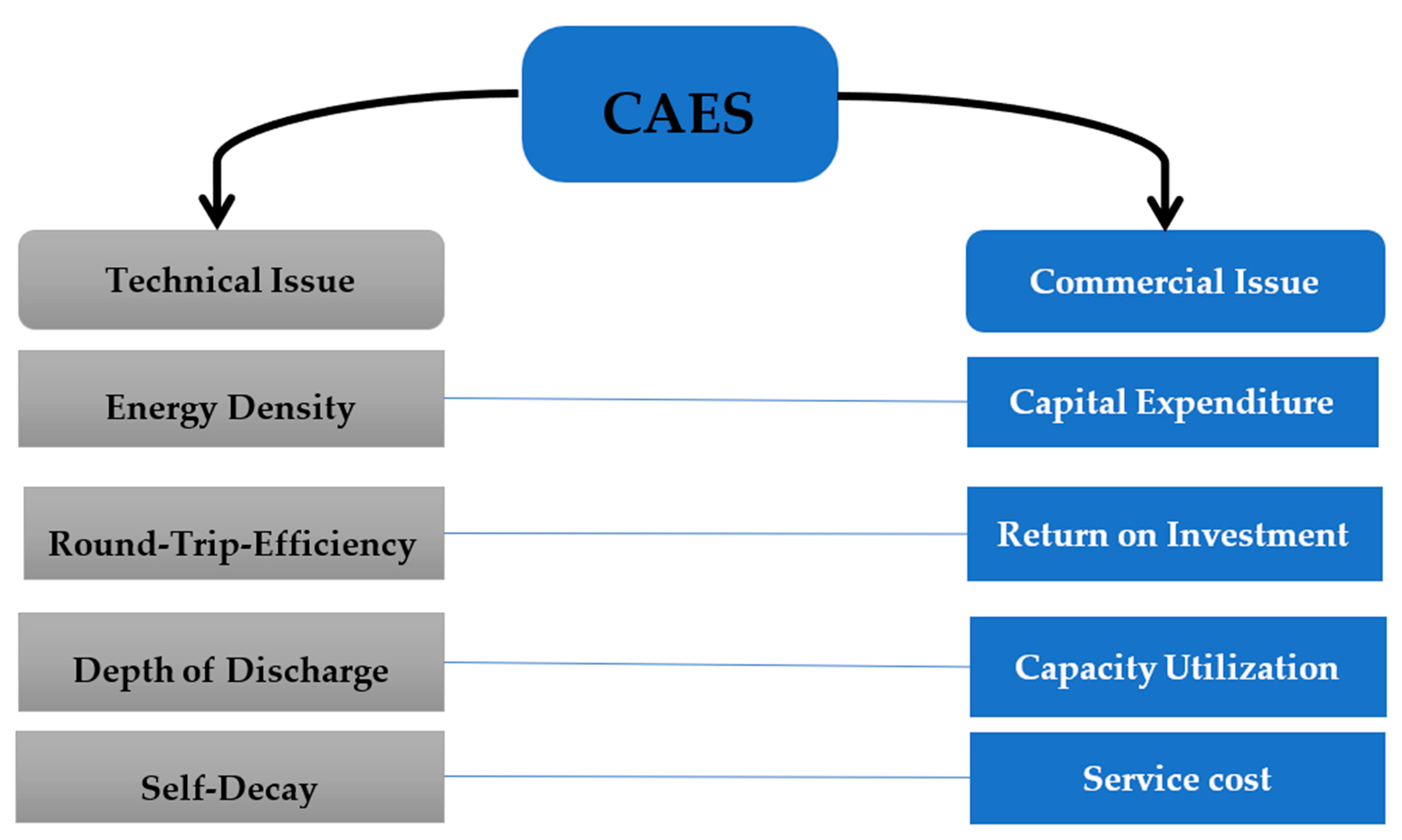
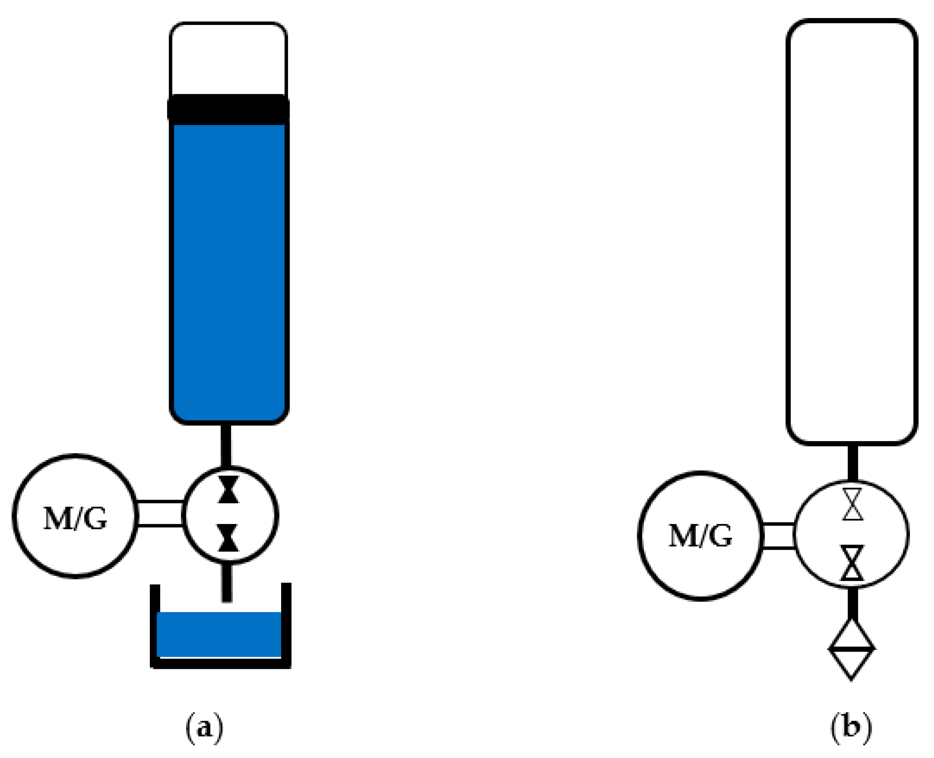
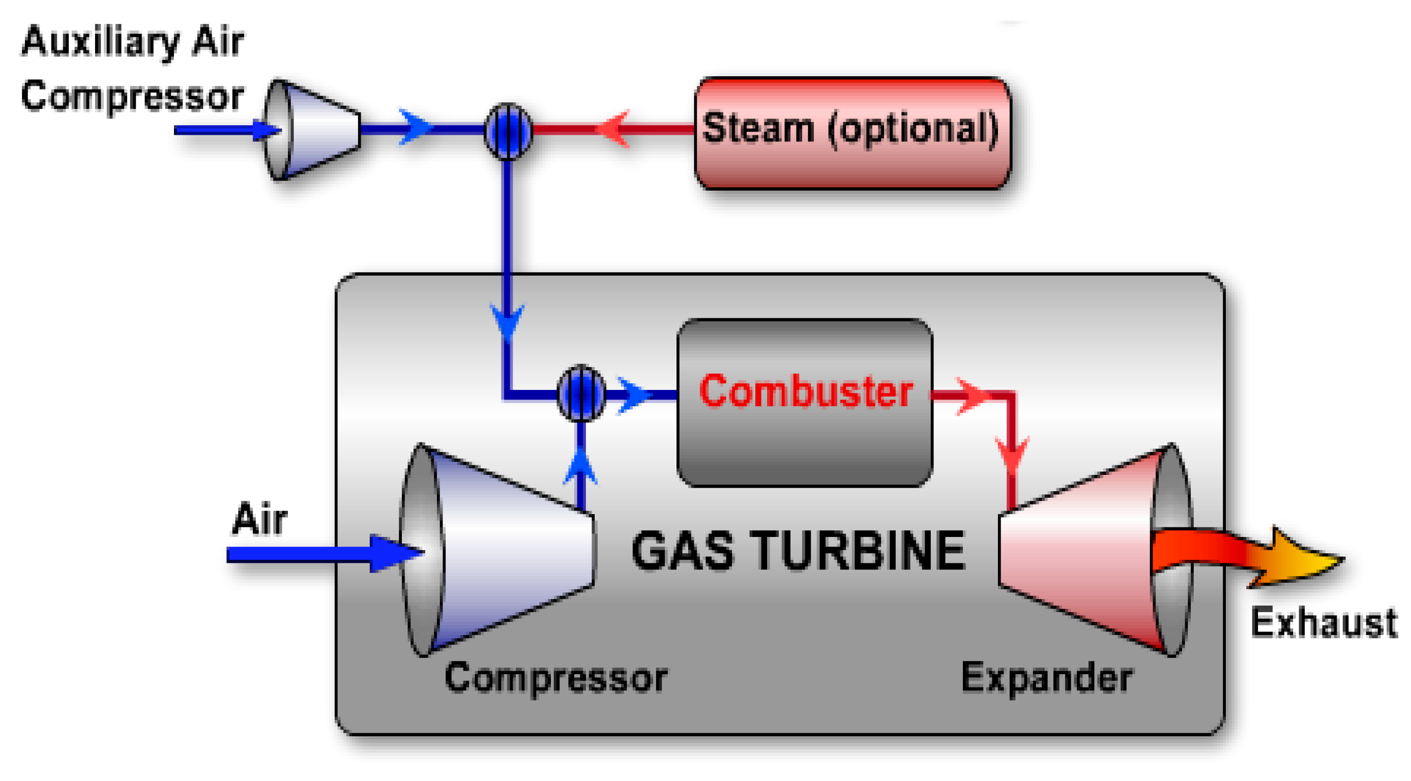
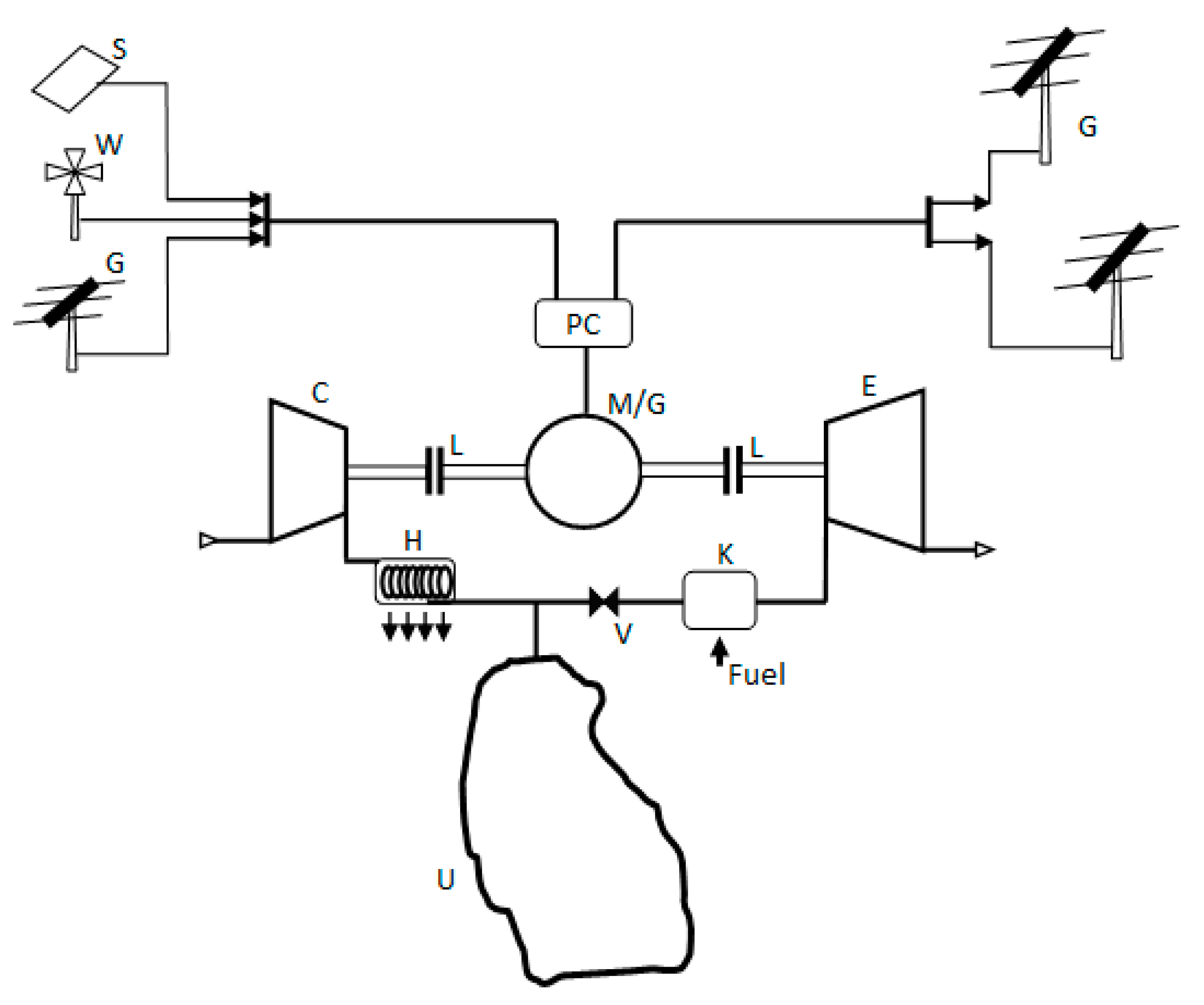
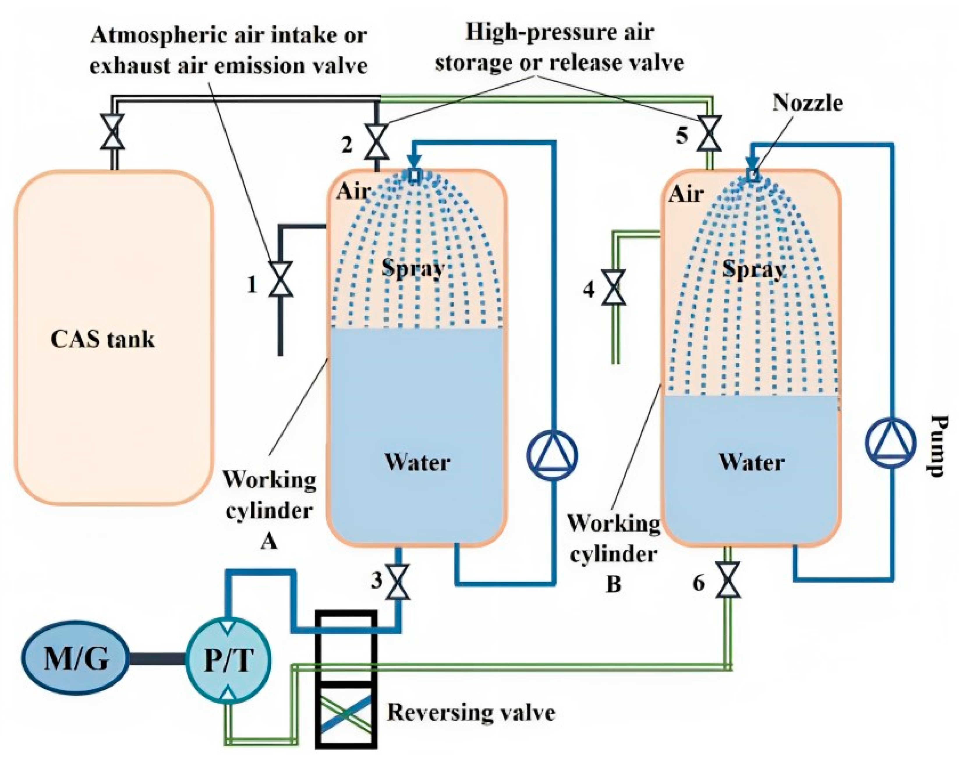
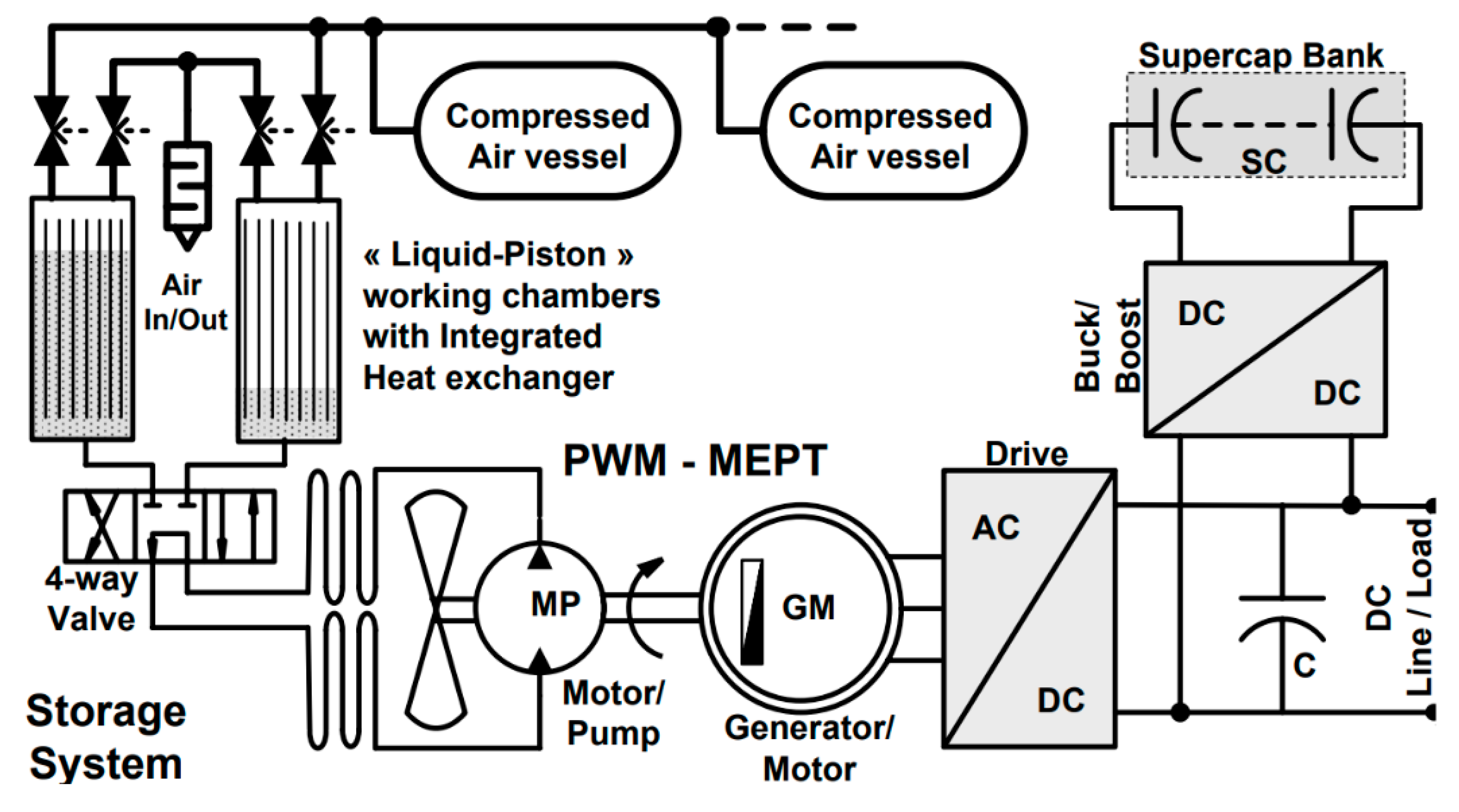
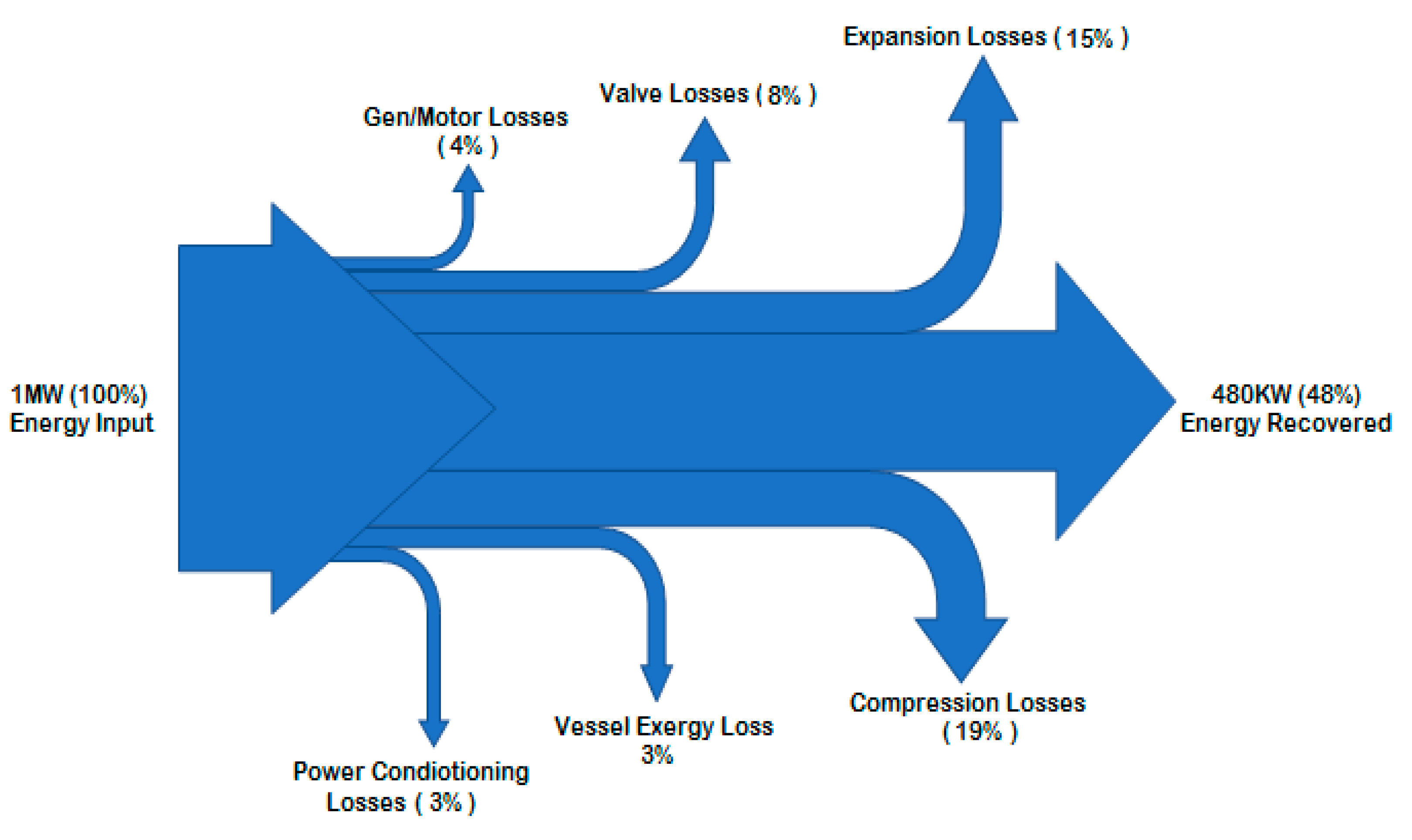
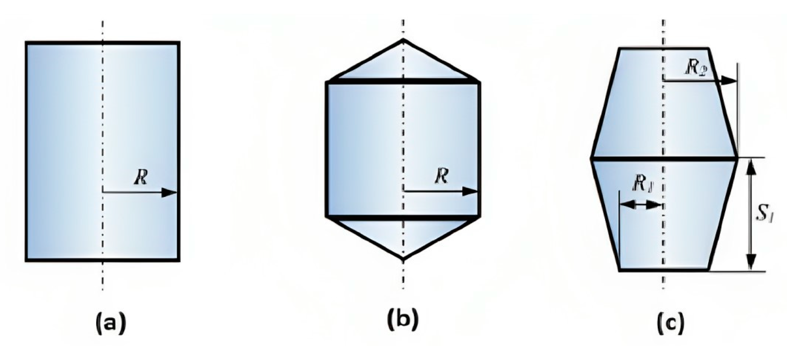

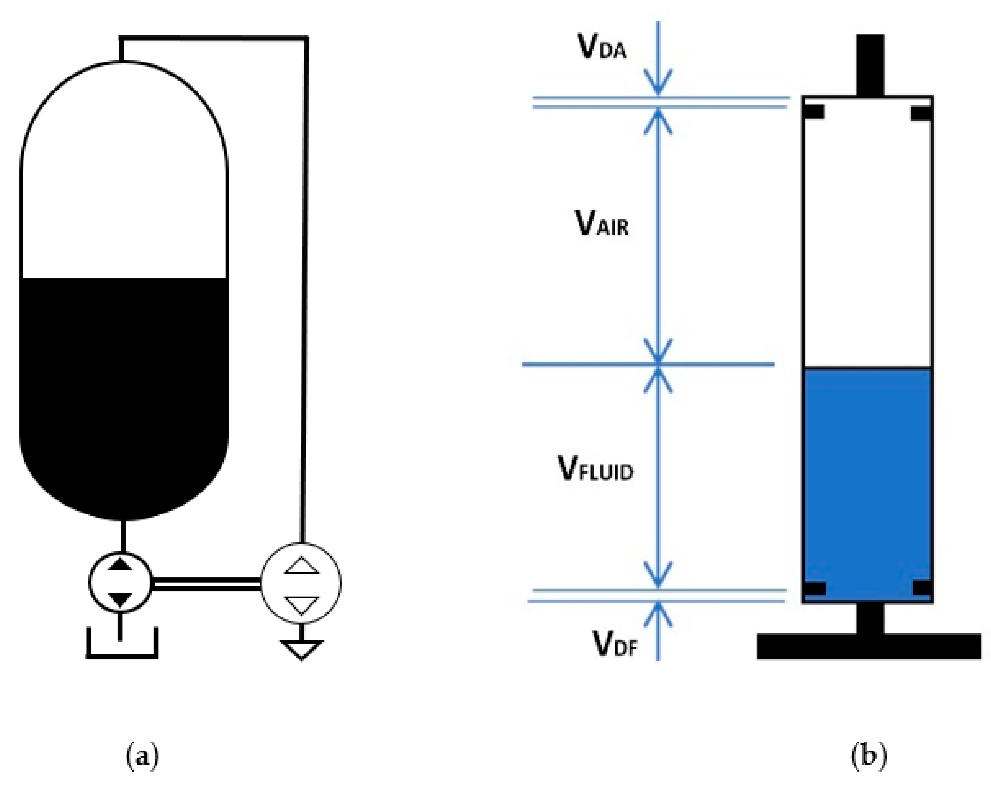
